

 Manufacturers
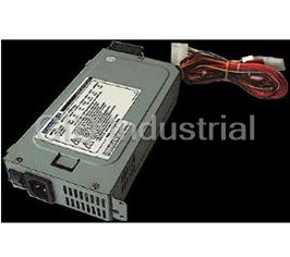
ELANVITAL EVN-1216

Description
Elan Vital EVN-1216 Power Supply. 121W | Flex-ATX
Part Number
EVN-1216
Price
Request Quote
Manufacturer
ELANVITAL
Lead Time
Request Quote
Category
POWER SUPPLY
Specifications
Dimensions
Width: 3.2"; Height: 1.7"; Depth: 6"
Input Voltage
88 - 264 Volts AC
Power Connectors
One (1) 21-inch large power connector (4-pin); One (1) 14-inch large power connector (4-pin); One (1) ATX power connector; One (1) 14-inch 12V P4 ATX power connector (4-pin)
SATA Connections
One (1) 14-inch SATA Connections
Technology
mITX Technology
Voltage
+5V (13A); -5V (0.5A); +12V1 (9A); +12V2 (9A); -12V (0.8A); +3.3V (13A); +5V-SB (2.5A)
Features
- Input Voltage: 88 - 264 Volts AC
- mITX Technology
- One (1) 14-inch 12V P4 ATX power connector (4-pin)
- One (1) 14-inch large power connector (4-pin)
- One (1) 14-inch SATA Connections
- One (1) 21-inch large power connector (4-pin)
- One (1) ATX power connector
- Voltage: +5V (13A); -5V (0.5A); +12V1 (9A); +12V2 (9A); -12V (0.8A); +3.3V (13A); +5V-SB (2.5A)
- Width: 3.2"; Height: 1.7"; Depth: 6"
Datasheet

Extracted Text
SPECIFICATION ARP-2005-00 SWITCHING POWER SUPPLY December 1, 2006 Aras Power Technologies Part Number: ARP-2005-00 Revision History of SPECIFICATION Rev. Description of Changes Owner Approve Date d Preliminary Specificaiton Sam 01-12-2006 00 Aras Power Technologies Part Number: ARP-2005-00 Table of Contents 1. SCOPE....................................................................................................................................................................................5 2. INPUT CHARACTERISTICS .............................................................................................................................................5 2.1 INPUT VOLTAGE .................................................................................................................................................................5 2.2 INPUT FREQUENCY .............................................................................................................................................................5 2.3 INPUT CURRENT ..................................................................................................................................................................5 2.4 POWER FACTOR ..................................................................................................................................................................5 2.5 IN-RUSH CURRENT .............................................................................................................................................................5 2.6 INPUT LEAKAGE CURRENT .................................................................................................................................................5 2.7 ISOLATION (HI-POT) ...........................................................................................................................................................5 2.8 HARMONIC CURRENT .........................................................................................................................................................5 2.9 POWER LINE TRANSIENT ....................................................................................................................................................5 2.10 ELECTROSTATIC DISCHARGE (ESD).................................................................................................................................5 3. OUTPUT CHARACTERISTICS .........................................................................................................................................6 3.1 OUTPUT CHARACTERISTICS................................................................................................................................................6 3.2 CROSS REGULATION..........................................................................................................................................................6 3.3 DYNAMIC LOAD RESPONSE TIME .......................................................................................................................................7 3.4 OVERSHOOT........................................................................................................................................................................7 3.5 EFFICIENCY ........................................................................................................................................................................7 4. TIME SEQUENCE................................................................................................................................................................8 4.1 OUTPUT VOLTAGE TIMING ..............................................................................................................................................10 4.1.1 OUTPUT RISE TIME(TVOUT_RISE) ................................................................................................................................10 4.1.2 TURN ON TIME BETWEEN EACH MAIN OUTPUTS(TVOUT_ON).....................................................................................10 4.1.3 OUTPUT VOLTAGE TURN OFF TIME(TVOUT_OFF) .......................................................................................................10 4.2 AC TURN ON / OFF TIMING .............................................................................................................................................10 4.2.1 5VSB TURN ON DELAY TIME (T )...................................................................................................................10 SB_ON_DELAY 4.2.2 AC TURN ON DELAY TIME (T ) ......................................................................................................................10 AC_ON_DELAY 4.2.3 5VSB TO MAIN OUTPUT TIME(T ) .......................................................................................................................10 SB_VOUT 4.2.4 POK TURN ON TIME (T )........................................................................................................................................10 POK_ON 4.2.5 HOLD-UP TIME(T _ ) .........................................................................................................................................10 VOUT HOLDUP 4.2.6 POK TURN OFF TIME (T )......................................................................................................................................10 POK_OFF 4.3 PSON TURN ON / OFF TIMING........................................................................................................................................10 4.3.1 PSON TURN ON DELAY TIME (T ) ...............................................................................................................10 PSON_ON_DELAY 4.3.2 POK TURN ON TIME (T ).......................................................................................................................................10 POK_ON 4.3.3 PSON DEACTIVE TO POK BEING DEASSERTED TIME(T )...................................................................................10 POSN_POK 4.3.4 POK TURN OFF TIME (T )......................................................................................................................................10 POK_OFF 5 SIGNALS AND INDICATOR FUNCTIONS.....................................................................................................................11 5.1 PSON (REMOTE TURN ON PSU CONTROL)......................................................................................................................11 5.2 POK (POWER OK) ...........................................................................................................................................................11 6. PROTECTIONS ..................................................................................................................................................................12 6.1 OVER-VOLTAGE PROTECTION ..........................................................................................................................................12 6.2 OVER CURRENT PROTECTION...........................................................................................................................................12 6.3 SHORT CIRCUIT PROTECTION ...........................................................................................................................................12 6.4 NO LOAD OPERATION.......................................................................................................................................................12 6.5 RESET AFTER SHUTDOWN ................................................................................................................................................12 6.6 INPUTS OVER CURRENT PROTECTION...............................................................................................................................12 7. PHYSICAL CHARACTERISTICS ...................................................................................................................................13 7.1 WEIGHT : 0.85 KGS....................................................................................................................................................13 7.2 CAGE DIMENSION : 82.00MM(W) × 43MM(H)×190 MM(L)..............................................................................................13 7.3 OUTPUT DC CONNECTORS........................................................................................................................................14 Aras Power Technologies Part Number: ARP-2005-00 8.ENVIRONMENTAL REQUIREMENTS ..........................................................................................................................15 8.1 TEMPERATURE..................................................................................................................................................................15 8.2 RELATIVE HUMIDITY........................................................................................................................................................15 8.3 ACOUSTIC .....................................................................................................................................................................15 9. REGULATORY AGENCY CERTIFICATION ...............................................................................................................15 9.1 RFI/EMI STANDARDS ......................................................................................................................................................15 9.2 SAFETY STANDARDS.........................................................................................................................................................15 Aras Power Technologies Part Number: ARP-2005-00 1. SCOPE This specification describes the physical, functional and electrical characteristics of the 200 watts, 5-outputs which +3.3V,+5V,+12V,-12V and +5VSB, switching power supply. The power supply is power factor corrected. 2. INPUT CHARACTERISTICS 2.1 Input Voltage Nominal input voltage: 90-264 Vrms 2.2 Input Frequency Input frequency range: 47 Hz to 63 Hz 2.3 Input current Input current should be lower than 6/3 Arms under full-load and 115/230 Vrms input voltage conditions. 2.4 Power Factor The power factor shall be greater than 0.95 at full load / 100 Vrms input voltage conditions , and 0.9 at full load / 240Vrms input voltage conditions 2.5 In-Rush Current Under all other conditions, power supply should not be damaged. 2.6 Input Leakage Current Input leakage current from line to ground should less than 3.5mArms at 230 Vrms/ 60 Hz input. 2.7 Isolation (Hi-Pot) Primary to ground: 1800 Vac, 50Hz, 3 sec, cut –off current :10mA . 2.8 Harmonic Current Power Supply is designed to meet the EN 61000-3-2 Power Line Harmonic Current Requirement. 2.9 Power Line Transient The power supply shall comply with the following requirements and associated test parameters: IEC 1000-4-4: 1988 Elec. Fast Transients --- test level: ± 1000 volts on AC power port IEC 1000-4-5: High energy Transients --- test level: ± 2000 volts on AC power port The test should not result in: a). damage to the power supply. b). disruption of the normal operation of the power supply 2.10 Electrostatic Discharge (ESD) The power supply shall withstand ESD test voltage conditions at any point on the system enclosure, using the test setups and conditions as defined in IEC 1000-4-2, Level 4. The following test levels shall be used in test: 8 kV contact discharge; 15kV air discharge with no abnormal operation. The storage capacitance shall be 150 pF and the discharge resistance shall be 330 Ω. Aras Power Technologies Part Number: ARP-2005-00 3. OUTPUT CHARACTERISTICS 3.1 Output Characteristics Output voltage, load current, combine power limit, voltage regulation and output noise of power supply should meet the specifications, which defined on the tables below: 200W Outputs Characteristics Output V1 V2 V3 V4 Standby Voltage 3.3V 5V 12V -12V 5VSB Peak Current Max. Load 8A 13A 16A 0.3A 2A Min. Load 0.2A 0.5A 1.0A 0A 0A 3.3V & 5V Combined 80W -- Power Total Output Power 200W Load Reg.(V) 3.135 ~ 3.465 4.845 ~ 5.355 11.4 ~ 12.6 -10.8 ~ -13.2 4.75 ~ 5.25 Ripple & Noise (+/- mV) 100mV 100mV 200mV 200mV 100mV Note 1: The 3.3V and 5V combined power shall not be exceed 80 Watts Note 2: The 3.3V,5V and 12 V combined power shall not be exceed 200 watts. Note 3: Noise band-width is from DC to 20MHz. Note 4: Add 0.1uF ceramic in parallel with 10uF electrical capacitor are placed at point of Ripple and Noise measurement. Note 5: The total output power is 100% output load at Ambient 50 degree C 3.2 Cross Regulation Each output shall remain within the specified limits for the +5V, +3.3V and +12V which acceptable load combinations are in the following table. Cross Regulation Table Output Current (A) 3.3V and 5V Item Output Power Combined Power 3.3V 5V 12V -12V 5Vsb LOAD1 0.2 0.5 1 0.3 0 3.16 18.76 LOAD2 0.2 3 16 0.3 2 15.66 221.26 LOAD3 0.2 13 4 0.1 1 65.66 119.86 LOAD4 0.2 13 15 0 1 65.66 250.66 LOAD5 8 0.5 1 0 0 28.9 40.9 LOAD6 8 3 16 0.1 1 41.4 239.6 LOAD7 8 11 4 0.1 1 81.4 135.6 LOAD8 5 13 4 0.1 1 81.5 135.7 LOAD9 8 11 13.5 0.1 1 81.4 249.6 LOAD10 6 6.5 16 0.1 1 52.3 250.5 Aras Power Technologies Part Number: ARP-2005-00 3.3 Dynamic Load Response Time The +3.3VDC and +5VDC outputs transient response are measured by switching the output load from 70 to 100 to 70 percent of its full value. The +12V output transient response is measured by switching the output load from 50 to 100 to 50 percent of its full value. The transient slew rate will 2.5A/us at a frequency of 100 Hz and 50% duty cycle. The power supply should be stable under all transient conditions from any steady state load, and the over/undershoot should be within the regulation band Output Voltage Δ Step Load Size Load Slew Rate Capacitive Load +3.3V 30% of max load 2.5A / uS 6000uF +5V 30% of max load 2.5A / uS 6000uF +12V 50% of max load 2.5A / uS 6000uF -12V 0% of max load 2.5A / uS 350uF +5VSB 0% of max load 2.5A / uS 350uF 3.4 Overshoot Any output overshoot during turn-on shall not exceed 10% of nominal output voltage. 3.5 Efficiency 67% typical under full load and 115 Vrms input at Cross Regulation Load 4. Aras Power Technologies Part Number: ARP-2005-00 4. TIME SEQUENCE Here are the timing requirements for the power supply operation. The output voltages must rise from 10% to within regulation limits (T ) within 70ms. The +3.3V, +5V and +12Voutput voltages should start to rise approximately at the vout_rise same time. All outputs must rise monotonically. Each output voltage shall reach regulation within 50ms (T ) of each vout_on other during turn on of the power supply. Each output voltage shall fall out of regulation within 400msec (T ) of each vout_off other during turn off. Refer to Figure 1 Power Supply Timing. Figure 2 Turn-on Turn-off Timing shows the timing requirements for the power supply being turned on and off via the AC input with PSON held low, and the power supply being turned on and off with the PSON signal after AC input is applied. Output Voltage Timing Item Description Min Max Units T Output voltage rise time from each main output 1 70 msec vout_rise T All main outputs must be within regulation of each other within this time -- 50 msec vout_on T All main outputs must leave regulation within this time -- 400 msec vout_off Figure 1: Power Supply Timing Vout 10% Vout +5V +12V T vout_off T vout_rise T vout_on Aras Power Technologies Part Number: ARP-2005-00 AC Turn On/Turn Off Timing Item Description Min Max Units T Delay from AC being applied to 5VSB being within regulation -- 1800 msec sb_on_delay T Delay from AC being applied to all output voltages being within regulation -- 2500 msec ac_on_delay T Delay from 5VSB being in regulation to output voltages being in regulation at AC turn 50 1000 msec sb_vout T Delay from output voltages within regulation limits to POK asserted at turn on 100 1000 msec pok_on T Time all output voltages stay within regulation after loss of AC 16 -- msec vout_holdup T Delay from POK deasserted to output voltages dropping out of regulation limits 1 -- msec pok_off PSON Turn On/Turn Off Timing Item Description Min Max Units T Delay from PSON# active to output voltages within regulation limits 5 400 msec pson_on_delay T Delay from output voltages within regulation limits to POK asserted at turn on 100 1000 msec pok_on T Delay from PSON# deactive to POK being deasserted -- 100 msec pson_pok T Delay from POK deasserted to output voltages dropping out of regulation limits 1 -- msec pok_off Figure 2 Timing Diagram AC Input T ac on delay T voutholdup Vout T T POK off POK on T T POK on POK off POK T PSON POK 5VSB T sb vout T PSON on delay T sb on delay PSON PSON turn on/off cycle AC turn on/off cycle Aras Power Technologies Part Number: ARP-2005-00 4.1 Output Voltage Timing 4.1.1 Output Rise Time(Tvout_rise) Output rise time of each main outputs should be greater than 1 msec and less than 70 msec. 4.1.2 Turn On Time Between Each Main Outputs(Tvout_on) All main outputs must be within regulation of each other within 50 msec. 4.1.3 Output Voltage Turn Off Time(Tvout_off) All main outputs must be leave regulation within 400 msec. 4.2 AC Turn On / Off Timing 4.2.1 5VSB Turn On Delay Time (T ) sb_on_delay 5VSB Turn on Delay time is measured from AC turn-on to the moment that +5VSB output stays within regulation limit. 5VSB shall be stable and stay within regulation limits less then 1800 msec under any load and line conditions. 4.2.2 AC Turn On Delay Time (T ) ac_on_delay AC Turn on Delay time is measured from AC turn-on to the moment that +5V output stays within regulation limit. All outputs shall be stable and stay within individual regulation limits less then 2500 msec under any load and line conditions. 4.2.3 5VSB To Main Output Time(T ) sb_vout 5VSB To Main Output Time is measured from 5VSB being in regulation to output voltages being in regulation at AC turn on. It should be greater than 50 msec and less than 1000 msec. 4.2.4 POK Turn On Time (T ) pok_on POK Turn on Time is measured from output voltages within regulation limits to POK asserted at turn on under any load and line conditions. It should be greater than 100 msec and less than 1000 msec. 4.2.5 Hold-Up Time(T _ ) vout holdup Under 100 Vrms and 80% output load conditions, unit shall continue to supply regulated outputs for at least 16 msec after lose of AC input. 4.2.6 POK Turn Off Time (T ) pok_off POK Turn off Time is measured from POK deasserted to output voltages dropping out of regulation limits at turn off under any load and line conditions. It should be greater than 1 msec. 4.3 PSON Turn On / Off Timing 4.3.1 PSON Turn On Delay Time (T ) pson_on_delay PSON Delay time is measured from PSON active low to output voltages within regulation limits. It should be greater than 5 msec and less then 400 msec under any load and line conditions. 4.3.2 POK Turn On Time (T ) pok_on POK Turn on Time is measured from output voltages within regulation limits to POK asserted at turn on under any load and line conditions. It should be greater than 100 msec and less than 1000 msec. 4.3.3 PSON Deactive To POK Being Deasserted Time(T ) posn_pok PSON Deactive To POK Being Deasserted Time is measured from PSON deactive to POK being deasserted. It should be less than 100 msec. 4.3.4 POK Turn Off Time (T ) pok_off POK Turn off Time is measured from POK deasserted to output voltages dropping out of regulation limits at turn off under any load and line conditions. It should be greater than 1 msec. Aras Power Technologies Part Number: ARP-2005-00 5 SIGNALS AND INDICATOR FUNCTIONS 5.1 PSON (Remote turn on PSU Control) The PSON signal is required to remotely turn on the power supply. PSON is an active low signal that turns on the +3.3V, +5V, and +12V power rails. When this signal is pulled high by the system, or left open, the outputs shall be turn off. PSON Signal Characteristics Signal Type Description PS KILL = Low PSU On PSU Off PS KILL = Open PS KILL = High PSU Off MIN MAX Logic level low (power supply ON) 0V 1.0V Logic level high (power supply OFF) 2.0V 5.25V Source current, Vpson = low -- 4mA 5.2 POK (Power OK) POK is a power OK signal and will be pulled HIGH by the power supply to indicate that all the outputs are within the regulation limits of the power supply . When any output voltage falls below regulation limits or when AC power has been removed for a time sufficiently long so that power supply operation is no longer guaranteed , POK will be de-asserted to a LOW state . See Figure 2 for a representation of the timing characteristics of POK .The start of the POK delay time shall be inhibited as long as any power supply outputs is in current limit. POK Signal Characteristics Signal Type +5V TTL Compatible signal Power OK POK = High POK = Low Power not OK MIN MAX Logic level low -- 0.4V Logic level high 2.4V 5.25V Source current, Vpson = low -- 4mA T 100msec 1000msec pok_on T 1msec -- pok_off Aras Power Technologies Part Number: ARP-2005-00 6. PROTECTIONS 6.1 Over-Voltage Protection The power supply over voltage protection shall be locally sensed. The power supply shall shutdown and latch off after an # over voltage condition occurs. This latch shall be cleared by toggling the PSON signal or by an AC power interruption contains the over voltage limits. The values are measured at the output of the power supply’s connectors. The voltage shall never exceed the maximum levels when measured at the power pins of the power supply connector during any single point of fail. The voltage shall never trip any lower than the minimum levels when measured at the power pins of the power supply connector. Over Voltage Limits Output Voltage MAX (V) 3.3V 4.3 5V 6.5 12V 15.6 6.2 Over Current Protection This power supply is designed to shutdown in a latch off mode after a current overload. The latch is then cleared by cycling the PS-ON signal in the OFF condition. Over Current Limits Output Voltage MAX (A) 3.3V 35 5V 35 12V 20 6.3 Short Circuit Protection An output short circuit is defined as any output impedance less than 0.1 ohms. The power supply shall shutdown and latch off for shorting +3.3V,+5V or +12V rail to secondary return. But the power supply shall recover automatically or by cycling the PS-ON once the short is removed. 6.4 No Load Operation When primary power is applied and with no load on any output, neither damage nor hazardous condition shall occur. The power supply may latch into shutdown state. 6.5 Reset After Shutdown If the power supply latches into a shutdown state, power supply shall return to normal operation only after the fault has been removed and a power off/on cycle is complete. The power off/on cycle may be performed by disconnecting the AC input or by transiting the PS-ON signal for high to low state. 6.6 Inputs Over Current Protection The power supply shall incorporate one input fuse on the LINE side for input over-current protection to prevent damage to the power supply and meet product safety requirements. Fuses should be slow blow type or equivalent to prevent nuisance trips. AC inrush current shall not cause the AC line fuse to blow under any conditions. All protection circuits in the power supply shall not cause the AC fuse to blow unless a component in the power supply has failed. This includes DC output load short conditions. Aras Power Technologies Part Number: ARP-2005-00 7. PHYSICAL CHARACTERISTICS 7.1 Weight : 0.85 Kgs 7.2 Cage Dimension : 82.00mm(W) × 43mm(H)×190 mm(L) Aras Power Technologies Part Number: ARP-2005-00 7.3 OUTPUT DC CONNECTORS P1 Baseboard Power Connector Connector housing: P2 - I4002 or equivalent PIN SIGNAL 18 AWG COLOR PIN SIGNAL 18 AWG COLOR 1 +3.3 VDC Orange 11 +3.3 VDC Orange 2 +3.3 VDC Orange 12 -12 VDC Blue 3 COM Black 13 COM Black 4 +5 VDC Red 14 PS_ON Green 5 COM Black 15 COM Black 6 +5 VDC Red 16 COM Black 7 COM Black 17 COM Black 8 P.G Gray 18 -- -- 9 +5VSB Purple 19 +5 VDC Red 10 +12V Yellow 20 +5 VDC Red P3 Floppy Power Connectors Connector housing: Amp 171822-4 or equivalent Pin Signal 18 AWG Color 1 +12 V Yellow 2 COM Black 3 COM Black 4+5 V Red P2,P4,P5 Peripheral Power Connectors Connector housing: Amp P4-A10202 or equivalent Pin Signal 18 AWG Color 1 +12 V Yellow 2 COM Black 3 COM Black 4+5 V Red P6 Process Power Connectors Connector housing: Amp P4-I4002 or equivalent Pin Signal 18 AWG Color COM Black 1 COM Black 2 +12V Yellow 3 +12V Yellow 4 Aras Power Technologies Part Number: ARP-2005-00 8.ENVIRONMENTAL REQUIREMENTS 8.1 Temperature Operating: 10°C to 50°C Non–Operating: -40°C to 70°C 8.2 Relative Humidity Operating: 5% to 90 % relative humidity (non-condensing) Non-operating: 5% to 90 % relative humidity (non-condensing) 8.3 ACOUSTIC The PSU audible noise will not excess of 37dbMAX,at a distance of 50cm for 50% load. 9. REGULATORY AGENCY CERTIFICATION 9.1 RFI/EMI Standards The power supply, when installed in system, shall comply with the following radiated and conducted emissions standards: a) FCC part 15, Subpart B, Class B computing devices. b) CISPR22-B(EN55022) 9.2 Safety Standards The power supply shall be approved/licensed/certified as the following safety standards, a) UL b) TUV c) CE d) CB e) FCC f) BSMI g) CCC
Frequently asked questions
What makes Elite.Parts unique?

What kind of warranty will the EVN-1216 have?
Which carriers does Elite.Parts work with?
Will Elite.Parts sell to me even though I live outside the USA?
I have a preferred payment method. Will Elite.Parts accept it?
Why buy from GID?

Quality
We are industry veterans who take pride in our work

Protection
Avoid the dangers of risky trading in the gray market

Access
Our network of suppliers is ready and at your disposal

Savings
Maintain legacy systems to prevent costly downtime

Speed
Time is of the essence, and we are respectful of yours
Related Products
Request a Quote

The quote request has been received
Close

Facing challenges or have inquiries? Feel free to contact us!
Call Us +1-469-283-2440
What they say about us
FANTASTIC RESOURCE
One of our top priorities is maintaining our business with precision, and we are constantly looking for affiliates that can help us achieve our goal. With the aid of GID Industrial, our obsolete product management has never been more efficient. They have been a great resource to our company, and have quickly become a go-to supplier on our list!
Bucher Emhart Glass
EXCELLENT SERVICE
With our strict fundamentals and high expectations, we were surprised when we came across GID Industrial and their competitive pricing. When we approached them with our issue, they were incredibly confident in being able to provide us with a seamless solution at the best price for us. GID Industrial quickly understood our needs and provided us with excellent service, as well as fully tested product to ensure what we received would be the right fit for our company.
Fuji
HARD TO FIND A BETTER PROVIDER
Our company provides services to aid in the manufacture of technological products, such as semiconductors and flat panel displays, and often searching for distributors of obsolete product we require can waste time and money. Finding GID Industrial proved to be a great asset to our company, with cost effective solutions and superior knowledge on all of their materials, it’d be hard to find a better provider of obsolete or hard to find products.
Applied Materials
CONSISTENTLY DELIVERS QUALITY SOLUTIONS
Over the years, the equipment used in our company becomes discontinued, but they’re still of great use to us and our customers. Once these products are no longer available through the manufacturer, finding a reliable, quick supplier is a necessity, and luckily for us, GID Industrial has provided the most trustworthy, quality solutions to our obsolete component needs.
Nidec Vamco
TERRIFIC RESOURCE
This company has been a terrific help to us (I work for Trican Well Service) in sourcing the Micron Ram Memory we needed for our Siemens computers. Great service! And great pricing! I know when the product is shipping and when it will arrive, all the way through the ordering process.
Trican Well Service
GO TO SOURCE
When I can't find an obsolete part, I first call GID and they'll come up with my parts every time. Great customer service and follow up as well. Scott emails me from time to time to touch base and see if we're having trouble finding something.....which is often with our 25 yr old equipment.
ConAgra Foods