

 Manufacturers
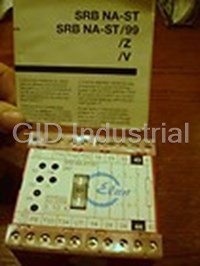
ELAN SRB-NA-ST99
Description
Elan SRB-NA-ST99 Module - Emergency Stop Relay
Part Number
SRB-NA-ST99
Price
Request Quote
Manufacturer
ELAN
Lead Time
Request Quote
Category
PRODUCTS - S
Datasheet

Extracted Text
m e a l d b i e at f p r o m m o c 1 0 y 0 ll % Elan Schaltelemente GmbH & Co. KG Safety Relay Modules Catalogue SRB-G L1 OPEN **** CLOSED K B Reset K A 47 57 C C1 X2 X2.1 S1 X1 S2 13 23 33 (43) (53) K1 K2 F2 * K1 Trigger circuit F1 K1 K A K4 K3 K3 TIMER TIMER K2 K2 K B K1 K3 K2 K4 K4 D D1 L62 14 24 34 48 58 (44) (54) K K A B N In the interests of a sustainable use of our world’s resources, this catalogue has been printed on 100% recycled paper on the basis of the latest environmental technology. a t r n e New: Modules SRB- C.44, -45, -46, -47 e c m y c n l o e ir d v p n a E p e r Catalogue SRB-G Safety Relay Modules Contents Page General 3 1 New products: – SRB-C.44, -C.45, -C.46, -C.47 6 2 SRB modules 22.5 mm wide – STOP category 0 25 3 SRB modules 22.5 mm wide – STOP category 1 47 4 SRB modules 45 mm wide – Standard version, STOP category 0 53 5 SRB modules 45 mm wide – Standard version, STOP category 1 67 6 SRB modules 45 mm wide – Multifunctional version, STOP category 0 73 7 SRB modules 45 mm wide – Multifunctional version, STOP category 1 87 8 SRB modules 45 mm wide – Special versions 101 9 SRB modules 90 mm wide – Standard version 111 10 SRB modules 90 mm wide – Special versions 117 11 Modules for contact multiplying 143 General technical data 157 Modules for special applications 158 Scope of products 161 The descriptions, control relationships, Or as the ancient Greeks already knew: We accept no liability for errors. data on external actuators, notes on Technical data subject to change without The Gods do not reveal everything to installation and operation etc. are notice. The data quoted in this list are mortals right at the start. But we find out provided on the best of our knowledge. typical series values which have been what is better during the course of time This does not however mean that any carefully checked. by searching. warranted characteristics or other claims relevant to liability over and above the Xenophanes (Greek philosopher, born "General Terms and Conditions for 570/588 BC) Supply of Goods and Services from the Electrical Industry" can be deduced from them. The user is not therefore released from the obligation to check our data and recommendations for his own use prior to operation. We trust this will be under- stood and this note observed. 1 2 Safety Relay Modules Guide to Products SRB 3 General The significant feature of in this Furthermore in housings with Modules which are not listed in this Compact latest issue described Safety Relay 45 mm width modules with addi- guide, in particular older SRB housings Modules (or SRB modules) is tional setting and adjustment modules are still on sale. Please ask highlighting the advantage of advantages are available and also for extra data sheet. increased functionality, but with modules for some special applica- reduced space consumption. tions. Some exceptions are realized in 90 mm housings. Standard modules, some with additional technical features are Parallel to these standard housings offered in housings, 22.5 mm wide also the product family SRBF – only and 45 mm wide. modules in special housings, 36 mm wide – will be continued Advantages Safety Relay Modules in ready-to- Because of the ready-to-install The use of Safety Relay Modules is install compact housings with snap compact housings Safety Relay saving significantly time for wiring. on fixing are containing a fail-safe Modules can be placed directly into Furthermore errors in design state and error tolerant electric circuit, the control cabinet very simple and and errors during wiring are designed to meet the requirements space saving. eliminated and therefore no extra of control category 3 and/or 4 time for trouble shooting and repair (EN 954-1), depending on the needs to be considered. external wiring. 4 . . T T R R E E Z Z F F Approvals Ü Ü ET BIA Certifications of all essential SRB For SRB modules test certificatesBerufsgenossenschaftliches basic circuits issued by component from the following authorities have Institut für Arbeitssicherheit test-authorities provide the user with been issued (for details see technical BIA, St. Augustin, extra security ensuring that this data): Canadian Standard Association obligations in respect to product Prüfstelle der BG Feinmechanik CSA, liability are fulfilled. und Elektrotechnik, Cologne, Underwriters Laboratories Inc.UL. Determination Although all SRB circuits meet the The scope below shall give assis- For better transparency the follow- specific requirements related to the tance in selecting the appropriate ing illustration and technical data are protection in case of failures module. filed on the basis of general charac- (EN 60 204-1 : 1998-11, part 9.4) teristics and functions, but not the various models differ in some following the historic sequential important details. number allocation C.XX. Literature • EN 60 204-1 : 1998-11: Electrical equipment of machines • EN 954-1: Safety related parts of control systems – General principles of design • EN 1050: Risk assessment • BIA-Report 6/97: Kategorien für sicherheits- bezogene Steuerungen nach EN 954-1 • VDE-Schriftenreihe: Buchveröffentlichung "Absicherung von Maschinen vor gefahrbringenden Bewegungen" 5 R R P P - - G G B B New products: New products: Safety relay modules Safety relay modules SRB-C.44, -C.46, -C.47 SRB-C.44, -C.46, -C.47 More versatility with 16 terminals in 22.5 mm housing Owing to a housing 22.5 mm wide with 16 connecting terminals (instead of 12 so far) the new Safety relay modules Type SRB-C.44, -C.46 and -C.47 are now provided with additional functions which could not be offered till now in such housings. Please find below major data: SRB-C.44 (data sheet see page 8) – 3 safety enabling outputs, 1 monitoring contact – Dual-channel triggering for non-equivalent inputs – Suitable for reed switches due to current limitation and voltage limitation at input circuits – Selectable extras: Trailing edge function, Auto reset, cross-short recognition SRB-C.46 (data sheet see page 16) – 3 safety enabling outputs, 1 monitoring contact – Single- or dual-channel triggering – Suitable for signal processing of externally powered inputs SRB-C.47 (data sheet see page 20) – 2 enabling outputs, instantaneous,1 monitoring contact – 1 enabling output, drop-out-delayed 1 ... 30 sec. – Single- or dual-channel triggering – Suitable for signal processing of externally powered inputs – Selectable extras: Trailing edge function, Auto reset, cross-short recognition Safety relay modules SRB-C.46 and -C.47 with hybrid fuse As a further significant feature the modules SRB-C.46 and -C.47 are fitted with a so called hybrid fuse. In contrast to a fusible cut-out (glass tube type) the function will be restored automatically after a short circuit. As distinct from commercially standard electronic fuses, the hybrid fuse has a latch function and resets only after power down – power up. This kind of reset prevents the danger of an unintended restart in mode "Automatic start" after repairing a short circuit. 6 6 New products: New products: 1 1 Safety relay module Safety relay module SRB-C.45 (data sheet see page 12) SRB-C.45 With "long-life" feature provided by a complementary electronic circuit As the result of a complementary electronic circuit comprising photo MOS relays connected upstream of the safety releases, this new C.45 SRB component possesses the special feature that the mechanical and the electrical service life of the safety- orientated relay contacts have become approximately equal. With usual safety relay components, in contrast, a much shorter electrical service life compared to the mechanical service life arises from the switch load. This can be a particular technological disadvantage with applications with a large number of switching cycles, e.g. for the control of the working cycle of a machine. The complementary electronic circuit in the C.45 SRB component ensures that during the switching on or off of the safety releases, the electrical load is exclusively switched by the photos MOS relay, and that the relay contacts which switch at the same time remain free of the switch load, i.e. their electrical service life remains unaffected. The C.45 SRB component is suitable for 1 or 2 channel activation, either trailing edge, automatic start or cross fault monitoring, it has 2 safety queries available and one floating contact and one electronic feedback contact. The width of the component is 45 mm. Functional sequence Closing release: 1. Release is open 2. Relay contacts close 3. Semi-conductor switches voltage-free => release is closed 13 13 13 14 14 14 Opening release: 1. Release is kept open 2. Relay contacts are by the semi-conductor opened voltage-free 13 13 14 14 7 7 . T R E Z F SRB-C.44 Safety relay array for emergency stop devices, interlocking devices and others ☛2-channel triggering☛Cross-short recognition ☛Non-equivalent inputs☛22.5 mm housing ☛Current limitation at input circuits ☛Voltage limitation at input circuits ☛Selectable extras: – Trailing edge function – Auto reset Features – Relay output: 3 NO, 1 NC – Feedback loop – Housing 45 mm, made of (Auxiliary NC for monitoring thermoplastic in accordance with – Input for emergency stop must not be used in safety UL-94-V-0, red RAL 3000 or door monitoring enabling circuits!) – DIN rail mounting – LED’s for K1, K2, U i – Input for reset DIN EN 50 022 Approvals Ü Contact manufacturer Contact manufacturer 01041 Front view 13 23 33 L42 A1 X1 X2 X3 K1 Ui SRB-C.44 K2 A2 S21 S22 S14 14 24 34 S13 Product range Type Enabling outputs Operating voltage Part no. SRB-C.44 3 NO/1 NC 24 VAC/VDC 600 0101 8 R P - G B SRB-C.44 (continued) 1 Example for dual-channel door Wiring diagram monitoring and external reset button. L1 RESET OPEN Dual-channel output, suitable for contact CLOSED reinforcement or with positively guided K B contacts. **** **** = Feedback loop K A Wire breakage and earth leakage in the A1 X2 S13 S14 S21 S22 X3 X1 13 23 33 monitoring circuits are detected. ** Electronic fuse F1 ** (an external leading fuse T 0.5 A TRIGGER CIRCUIT is recommended) K1 K A Ui K2 K B K1 K2 A2 14 24 34 L42 K K B A N For further examples refer to page 10/11 Model specific Operating voltage 24VDC –15%/+20%, residual ripple max. 10% Technical data 24 VAC –15%/+10% (refer to page 157 Frequency 50/60 Hz (for AC operating) for general data) Fuse (power supply) T 0.5 A/250 V (internal electronic fuse, triggering current > 0.6 A, reset after 1 second) Power consumption max. 1.8 W; 2.4 VA, plus auxiliary output L42 Switching capacity (enabling contacts) 230 VAC, 4 A ohmic (inductive with suitable suppression) Fuse (enabling contacts) 4 A slow blowing Switching capacity (monitoring contacts) 24 VDC, 100 mA Current and voltage limitation of input circuits 26 VDC/100 mA Application category AC 15/DC 13, DIN VDE 0660 Part 200 Pick-up delay ≤ 120 ms/≤ 30 ms (Auto start, reset button) Drop-out delay ≤ 20 ms Contact material / contacts AgSnO, self cleaning, positively driven Contact resistance max. 100 mOhm when new Air and creeping distances DIN VDE 0110-1 (04.97), 4 kV/2 Connections Self lifting screw terminals min. 0.6 qmm, max. 2.5 qmm Dimensions H/W/D 90 mm/22.5 mm/121 mm Weight 235 g Ambient operating temperature –25 °C ... +45 °C (derating curve available) 7 Mechanical life 10 switching cycles Terminal labeling DIN EN 50 005/DIN 50 013 9 SRB-C.44 (continued) Wiring example: Wiring example: Input level Input level S21 S13 X1 S13 S21 X1 Dual-channel emergency Dual-channel door stop switch according to monitoring according to OPEN EN 60 204-1. EN 1088, one limit switch CLOSED with positive opening Wire breakage and earth contact. leakage in the emergency EMERGENCY RESET RESET stop circuits are detected. Wire breakage and earth STOP leakage in the door Cross-shorts in the monitoring circuits are emergency stop circuits are detected. detected. Cross-shorts in the door With external reset button. monitoring circuits are Safety category 3 or 4 detected. in accordance with With external reset button EN 954-1. for increased safety requirements. Safety category 3 or 4 S22 S14 X2 S22 S14 X2 in accordance with EN 954-1. Wiring example: Wiring example: Input level Input level S21 S13 X1 S21 S13 X1 Dual-channel door Dual-channel door monitoring with reed monitoring with reed switch. switch. Wire breakage and earth Wire breakage and earth leakage in the door leakage in the door monitoring circuits are monitoring circuits are detected. detected. Cross-shorts in the door Cross-shorts in the door monitoring circuits are monitoring circuits are detected. RESET detected. With external reset button Safety category 3 for increased safety in accordance with requirements. EN 954-1. Safety category 3 in accordance with EN 954-1. S22 S14 X2 S22 S14 X2 Advice: X1 For "Automatic Reset" X1 connect feed back loop to X1- X3 or apply jumper X1-X3 if no feed back loop is used. When using external reset button (feed back loop RESET connected to X1-X2), unit is triggered by trailing edge function. KA KA Trailing edge function with "fail-safe" function only by a DC power supply. KB KB After a performed "Emer- gency Shut Down" an auto- matic restart of the system must be prevented by the higher ranking electric X3 X2 circuitry when the relay module SRB-C.44/e is been set into mode "Auto-matic Start" (refer to EN 60204-1, part 9.2.5.4.2 and part 10.8.3). 10 SRB-C.44 (continued) 1 Wiring example: Wiring example: Power level Power level Single-channel output L1 L1 Dual-channel output L1 L1 L1 Suitable for contact Suitable for contact * * * * KA KA KB KB * reinforcement or contact KA KB reinforcement or contact KA KA KB KB multiplication, using relays multiplication, using relays X 1 X 1 X 2 X 2 13 13 X 1 X 2 13 X 1 X 2 13 23 X 1 X 2 13 23 or contactors with or contactors with KA KA KB KA positively guided contacts. positively guided contacts. KB 14 14 14 KB KB KB 14 14 24 24 KA KA KA KA KA KB KB KB KA KA KB KB N N N N N * Reset button wired in * Reset button wired in series to feedback loop. series to feedback loop. 11 . T R E Z F SRB-C.45 Safety relay array for emergency stop devices, interlocking devices and others ☛"Long life" module☛45 mm housing ☛1- or 2-channel triggering☛1 semiconductor output ☛3 enabling outputs and☛Selectable extras: 1 monitoring output – Trailing edge function ☛with integrated selective fuse – Auto reset ☛suitable for signal processing – Cross-short recognition of externally powered inputs Features – Relay output: 3 NO, – Input for reset – Housing 45 mm, made of 1 NC with non-equivalence. thermoplastic in accordance with – Feedback loop (Auxiliary NC for monitoring UL-94-V-0, red RAL 3000 must not be used in safety – Input for emergency stop – DIN rail mounting enabling circuits!) or door monitoring DIN EN 50 022-35 – Long life module for application – LED’s for K1, K2, U and U B i with high switching frequency. Electrical life approximate to mechanical life. Approvals Ü LR 13571-30 E 54284 (M) Pending Front view 23 41 13 33 X3 S11 A1 S12 X1 X2 SRB-C.45-24V U U Bi K1 K2 Fuse A2 S31 S32 S21 S22 14 24 34 42 L52 Product range Type Enabling outputs Operating voltage Part no. SRB-C.45 3 NO/1 NC 24 VAC/VDC 600 0102 12 R P - G B SRB-C.45 (continued) 1 Example for dual-channel door Wiring diagram L1 monitoring and external reset button. OPEN **** Dual-channel output, suitable for contact CLOSED K reinforcement or with positively guided B Reset contacts. K **** = Feedback loop A A1 S11 X3 X2 S12 X1 S22 S21 13 23 33 41 Wire breakage and earth leakage in the monitoring circuits are detected. * Fuse F2 (located in housing lid) 1 A, K1 K2 F2 Fuse F1 (internal) 1.25 A * K1 TRIGGER CIRCUIT K1 F1 K A K2 K2 K Ui UB B K1 K2 A2 S31 S32 L52 14 24 34 42 K K A B N For further examples refer to page 14/15 Model specific Operating voltage 24 VDC –15%/+20%, residual ripple max. 10% Technical data 24 VAC –15%/+10% (refer to page 157 Frequency 50/60 Hz (for AC operating) for general data) Fuse (power supply) F2: T 1.0 A/250 V (internal F1: T 1.25 A/250 V) Power consumption max. 3.4 W; 4.4 VA, plus auxiliary output L52 Switching capacity (enabling contacts) 60 VAC/VDC, 3 A ohmic (inductive with suitable suppression) Fuse (enabling contacts) 3 A slow blowing Switching capacity (monitoring contacts) 41/42: 24 V/2 A; L52: max. 100 mA Fuse (monitoring contacts) 41/42: 2 A slow blowing Application category AC 15/DC 13, DIN VDE 0660 Part 200 Pick-up delay ≤ 120 ms Drop-out delay ≤ 20 ms Contact material / contacts AgSnO, self cleaning, positively driven Contact resistance max. 100 mOhm when new Air and creeping distances DIN VDE 0110-1 (04.97), 4 kV/2 Connections Self lifting screw terminals min. 0.5 qmm, max. 2.5 qmm Dimensions H/W/D 83 mm/45 mm/140 mm Weight 460 g Ambient operating temperature 0 °C ... +45 °C (derating curve available) 7 Mechanical life 10 switching cycles Terminal labeling DIN EN 50 005/DIN 50 013 13 SRB-C.45 (continued) Wiring example: Wiring example: Input level Input level S31 S11 S12 X1 S31 S11 S21 X 1 Single-channel emergency Dual-channel emergency stop stop switch according to switch according to EN 60 204-1. EN 60 204-1. Wire breakage and earth Wire breakage and earth leakage in the emergency leakage in the emergency stop EMERGENCY RESET RESET EMERGENCY stop circuits are detected. circuits are detected. STOP STOP With external reset button. Cross-shorts in the emergency stop circuits are not detected. Safety category 2 in accordance with With external reset button. EN 954-1. Safety category 3 or 4 in accordance with EN 954-1. S12 S22 X2 S32 S12 S22 X 2 S32 Wiring example: Wiring example: Input level Input level S11 S31 X1 S21 S11 S12 X1 S31 Dual-channel emergency Single-channel door stop switch according to monitoring according to OPEN EN 60 204-1. EN 1088 limit switch with positive opening contact. CLOSED Wire breakage and earth leakage in the emergency Wire breakage and earth EMERGENCY RESET RESET stop circuits are detected. STOP leakage in the emergency stop circuits are detected. Cross-shorts in the emergency stop circuits are With external reset button. detected. Safety category 2 With external reset button. in accordance with EN 954-1. Safety category 3 or 4 in accordance with EN 954-1. S12 X2 S12 S32 X2 S22 S22 S32 Wiring example: Wiring example: Input level Input level S11 S21 X1 S31 S21 S11 S31 X1 Dual-channel door Dual-channel door monitoring according to monitoring according to OPEN OPEN EN 1088, one limit switch EN 1088, one limit switch CLOSED CLOSED with positive opening with positive opening contact. contact. RESET RESET Wire breakage and earth Wire breakage and earth leakage in the door leakage in the door monitoring circuits are monitoring circuits are detected. detected. Cross-shorts in the door Cross-shorts in the monitoring circuits are emergency stop circuits are not detected. detected. With external reset button. With external reset button. Safety category 3 or 4 Safety category 3 or 4 in accordance with in accordance with EN 954-1. EN 954-1. S12 S22 X2 S32 S12 S32 X2 S22 14 SRB-C.45 (continued) 1 Wiring example: Wiring example: Power level Power level Single-channel output. Dual-channel output. L1 L1 Suitable for contact Suitable for contact * * reinforcement or contact KA KB reinforcement or contact KA KB multiplication, using relays multiplication, using relays X1 X2 13 X1 X2 13 23 or contactors with or contactors with KA positively guided contacts. positively guided contacts. KB 14 14 24 KB KA KA KB KA KB N N * Reset button wired in * Reset button wired in series to feedback loop. series to feedback loop. 15 . T R E Z F SRB-C.46 Safety relay array for emergency stop devices, interlocking devices and others ☛1- or 2-channel triggering☛22.5 mm housing ☛3 enabling outputs and☛Selectable extras: 1 monitoring output – Trailing edge function ☛with electronic short circuit – Auto reset protection "Hybrid fuse" – Cross-short recognition ☛suitable for signal processing of externally powered inputs Features – Relay output: 3 NO, 1 NC – Feedback loop – Housing 22.5 mm, made of (Auxiliary NC for monitoring thermoplastic in accordance with – Input for emergency stop must not be used in safety UL-94-V-0, red RAL 3000 or door monitoring enabling circuits!) – DIN rail mounting – LED’s for K1, K2, U i – Input for reset DIN EN 50 022 Approvals Ü Contact manufacturer Contact manufacturer 01067 Front view 13 23 33 41 A1 S11 X1 X3 K1 Ui SRB-C.46 K2 A2 S12 S21 S22 14 24 34 42 Product range Type Enabling outputs Operating voltage Part no. SRB-C.46 3 NO/1 NC 24 VAC/VDC 600 0103 16 R P - G B SRB-NA-R-C.46 (continued) 1 Example for dual-channel door Wiring diagram monitoring and external reset button. L1 Reset OPEN Dual-channel output, suitable for contact CLOSED reinforcement with positively guided K B contacts. **** **** = Feedback loop K A Wire breakage and earth leakage in the A1 S12 S11 S21 S22 X3 X1 13 23 33 41 monitoring circuits are detected. ** Hybrid fuse F1 ** Trigger circuit K1 K A Ui K2 K B K1 K2 A2 14 24 34 42 K K A B N For further examples refer to page 18/19 Model specific Operating voltage 24 VDC –15%/+20%, residual ripple max. 10% Technical data 24 VAC –15%/+10% (refer to page 157 Frequency 50/60 Hz (for AC operating) for general data) Fuse (power supply) Internal electronic fuse, triggering current > 0.6 A, reset after power down Power consumption max. 2.4 W; 3.3 VA Switching capacity (enabling contacts) 230 VAC, 4 A ohmic (inductive with suitable suppression) Fuse (enabling contacts) 4 A slow blowing Switching capacity (monitoring contacts) 24 VDC, 2 A Fuse (monitoring contacts) 2 A slow blowing Application category AC 15/DC 13, DIN VDE 0660 Part 200 Pick-up delay ≤ 200 ms/≤ 30 ms (Auto start, reset button) Drop-out delay ≤ 20 ms Contact material / contacts AgSnO, self cleaning, positively driven Contact resistance max. 100 mOhm when new Air and creeping distances DIN VDE 0110-1 (04.97), 4 kV/2 Connections Self lifting screw terminals min. 0.6 qmm, max. 2.5 qmm Dimensions H/W/D 90 mm/22.5 mm/121 mm Weight 235 g Ambient operating temperature –25 °C ... +45 °C (derating curve available) 7 Mechanical life 10 switching cycles Terminal labeling DIN EN 50 005/DIN 50 013 17 SRB-C.46 (continued) Wiring example: Wiring example: Input level Input level S11 S12 S11 S11 S21 S11 Single-channel emergency Dual-channel emergency stop switch according to stop switch according to EN 60 204-1. EN 60 204-1. Wire breakage and earth Wire breakage and earth leakage in the emergency leakage in the Emergency EMERGENCY RESET EMERGENCY RESET stop circuits are detected. stop circuits are detected. STOP STOP To deactivate cross-short Cross-shorts in the monitoring: Set switch emergency stop circuits are "QS" (bottom of housing) not detected. to "0". To deactivate cross-short With external reset button. monitoring: Set switch "QS" (bottom of housing) Safety category 2 to "0". in accordance with QS QS EN 954-1. With external reset button. Safety category 3 or 4 0 1 0 1 S12 S21 X1 in accordance with S12 S22 X1 EN 954-1. Wiring example: Wiring example: Input level Input level S11 S21 S11 S11 S12 S11 Dual-channel emergency Single-channel door stop switch according to monitoring according to OPEN EN 60 204-1. EN 1088 limit switch with positive opening contact. CLOSED Wire breakage and earth leakage in the emergency Wire breakage and earth EMERGENCY RESET RESET stop circuits are detected. leakage in the emergency STOP stop circuits are detected. Cross-shorts in the emergency stop circuits are To deactivate cross-short detected. monitoring: Set switch "QS" (bottom of housing) Activating cross-short to "0". monitoring: Set switch "QS" (bottom of housing) With external reset button to "1". for increased safety requirements. QS QS With external reset button. Safety category 2 Safety category 3 or 4 0 1 0 1 in accordance with in accordance with S12 S22 X1 S12 S21 X1 EN 954-1. EN 954-1. Wiring example: Wiring example: Input level Input level +24V (S11) +24V (S22) S11 S11 S21 S11 Dual-channel door monitoring Dual-channel triggering according to EN 1088, one using P-switching OPEN limit switch with positive semiconductors. CLOSED opening contact. Wire breakage and earth Wire breakage and earth leakage in the door RESET RESET leakage in the door monitoring circuits are monitoring circuits are detected. detected. With external reset button. Cross-shorts in the door Attention: monitoring circuits are QS-switch must be set in detected. position "0". Activating cross-short WARNING: monitoring: Set switch "QS" Ignoring may destroy the (bottom of housing) to "1". QS QS device. With external reset button for Safety category 3 or 4 0 0 1 1 increased safety requirements. S12 S22 X1 S12 S21 X1 in accordance with Safety category 3 or 4 EN 954-1. in accordance with EN 954-1. 18 SRB-C.46 (continued) 1 Wiring example: Wiring example: Power level Power level Single-channel output Dual-channel output L1 L1 L1 L1 Suitable for contact Suitable for contact * * * * reinforcement or contact KA KB reinforcement or contact KA KB KA KA KB KB multiplication, using relays multiplication, using relays X 1 S11 13 D X2 13 X 1 D S11 X2 13 23 13 23 or contactors with or contactors with KA KA KB positively guided contacts. positively guided contacts. KB 14 14 KB KB 14 24 14 24 KA KA KA KB KA KB KA KB KA KB N N N N * Reset button wired in * Reset button wired in series to feedback loop. series to feedback loop. Advice For "Automatic Reset" S11 X1 connect feed back loop to X1- X3 or apply jumper X1-X3 if no feed back loop is used. When using external reset button (feed back loop RESET connected to S11-X1), unit is triggered by trailing edge function. KA KA Trailing edge function with "fail-safe" function only by a DC power supply. KB KB After a performed "Emer- gency Shut Down" an auto- matic restart of the system must be prevented by the higher ranking electric X3 circuitry when the relay X1 module SRB-C.46/e is been set into mode "Automatic Start" (refer to EN 60 204-1, part 9.2.5.4.2 and part 10.8.3). 19 . T R E Z F SRB-C.47 Safety relay array for emergency stop devices, interlocking devices and others ☛1- or 2-channel triggering☛22.5 mm housing ☛3 enabling outputs, instant and☛Selectable extras: 1 enabling output, drop-out delayed – Trailing edge function ☛with "Hybrid fuse" – Auto reset ☛suitable for processing of – Cross-short recognition externally powered input signals Features – Relay output: – Feedback loop – Housing 22.5 mm, made of 2 NO, instantaneous; thermoplastic in accordance with – Input for emergency stop 1 NO, drop-out delayed UL-94-V-0, red RAL 3000 or door monitoring – 1 semi-conductor output – DIN rail mounting – LED’s for K1, K2, K3/k4 and U i DIN EN 50 022 – Input for reset Approvals Ü Contact manufacturer Contact manufacturer 01069 Front view 13 23 37 X2 A1 S11 X1 X3 SRB-C.47 Ui K1 K2 K3/4 t: s A2 S12 S21 S22 14 24 38 L42 Product range Type Enabling outputs Operating voltage Part no. SRB-C.47 2 NO/1 NO /1 NC 24 VAC/VDC 600 0104 20 R P - G B SRB-C.47 (continued) 1 Example for dual-channel door Wiring diagram monitoring and external reset button. L1 RESET OPEN Dual-channel output, suitable for contact CLOSED reinforcement with positively guided K B contacts. **** **** = Feedback loop K A A1 S12 S11 S21 S22 X1 X2 X3 13 23 37 Wire breakage and earth leakage in the monitoring circuits are detected. ** Hybrid fuse F1 ** TRIGGER CIRCUIT K1 K A K3 Ui K2 K B K1 K2 K3 K4 K4 A2 L42 14 24 38 K K A B N For further examples refer to page 22/23 Model specific Operating voltage 24 VDC –15%/+20%, residual ripple max. 10% Technical data 24 VAC –15%/+6% (refer to page 157 Frequency 50/60 Hz (for AC operating) for general data) Fuse (power supply) Internal electronic fuse, triggering current < 0.6 A, reset after power down Power consumption max. 4 W; 5.5 VA, plus auxiliary output L42 Switching capacity (enabling contacts) 230 VAC, 4 A ohmic (inductive with suitable suppression) Fuse (enabling contacts) 4 A slow blowing Switching capacity (monitoring contacts) L42: 24 VDC, 100 mA Application category AC 15/DC 13, DIN VDE 0660 Part 200 13/14, 23/24: AC 15: 250 V/1.5 A; DC 13: 24 V/1.2 A 37/38: AC 15: 250 V/3 A; DC 13: 24 V/2 A Pick-up delay ≤ 120 ms/≤ 30 ms (Auto start, reset button) Drop-out delay ≤ 20 ms Contact material / contacts AgSnO, self cleaning, positively driven Contact resistance max. 100 mOhm when new Air and creeping distances DIN VDE 0110-1 (04.97), 4 kV/2 Connections Self lifting screw terminals min. 0.5 qmm, max. 2.5 qmm Dimensions H/W/D 90 mm/22.5 mm/121 mm Weight 235 g Ambient operating temperature –25 °C ... +45 °C (derating curve available) 7 Mechanical life 10 switching cycles Terminal labeling DIN EN 50 005/DIN 50 013 21 SRB-C.47 (continued) Wiring example: Wiring example: Input level Input level S11 S12 X1 S11 S21 X1 Single-channel emergency Dual-channel emergency stop stop switch according to switch according to EN 60 204-1. EN 60 204-1. Wire breakage and earth Wire breakage and earth leakage in the emergency leakage in the emergency stop EMERGENCY EMERGENCY RESET RESET stop circuits are detected. circuits are detected. STOP STOP To deactivate Cross-short Cross-shorts in the emergency monitoring: Set switch stop circuits are not detected. "QS" (bottom of housing) To deactivate cross-short to "0". monitoring: set switch "QS" With external reset button. (bottom of housing) to "0". Safety category 2 With external reset button. in accordance with Safety category 3 or 4 QS QS EN 954-1. in accordance with EN 954-1. 0 0 1 1 S12 S21 X2 S12 S22 X2 Wiring example: Wiring example: Input level Input level S11 S21 X1 S11 S21 X1 Dual-channel emergency Single-channel door stop switch according to monitoring according to OPEN EN 60 204-1. EN 1088 limit switch with positive opening contact. CLOSED Wire breakage and earth leakage in the emergency Wire breakage and earth EMERGENCY RESET RESET stop circuits are detected. leakage in the door STOP monitoring circuits are Activating cross-short detected. monitoring: Set switch "QS" (bottom of housing) To deactivate cross-short to "1". monitoring: set switch "QS" (bottom of housing) With external reset button. to "0". Safety category 3 or 4 With external reset button in accordance with QS for increased safety QS EN 954-1. requirements. 0 1 0 1 Safety category 2 S12 X2 S12 S22 X2 S22 in accordance with EN 954-1. Wiring example: Wiring example: Input level Input level X1 S11 S21 X1 +24V (S11) +24V (S22) Dual-channel door Dual-channel triggering monitoring according to using P-switching semi- OPEN EN 1088, one limit switch conductors. CLOSED with positive opening Wire breakage and earth contact. leakage in the door RESET RESET Wire breakage and earth monitoring circuits are leakage in the door detected. monitoring circuits are With external reset button. detected. Attention: Activating cross-short QS-switch must be set in monitoring: Set switch position "0". "QS" (bottom of housing) WARNING: to "1". Ignoring may destroy the With external reset button. QS QS device. Safety category 3 or 4 0 Safety category 3 or 4 in 1 1 0 in accordance with S12 S22 X2 S12 S21 X2 accordance with EN 954-1. EN 954-1. 22 SRB-NA-R-C.47 (continued) 1 Wiring example: Wiring example: Power level Power level Single-channel output Dual-channel output L1 L1 Suitable for contact Suitable for contact reinforcement or contact * reinforcement or contact * KA KB KA KB multiplication, using relays multiplication, using relays X 1 X2 13 X 1 X2 13 23 or contactors with or contactors with positively guided contacts. positively guided contacts. KA KB KB 14 14 24 KA KA KB KA KB N N * Reset button wired in * Reset button wired in series to feedback loop. series to feedback loop. Advice For "Automatic Reset" connect feed back loop to X1 X1 X1-X3 or apply jumper X1-X3 if no feed back loop is used. When using external reset button (feed back loop RESET connected to X1-X2), unit is triggered by trailing edge function. KA KA Trailing edge function with "fail-safe" function only by a DC power supply. KB KB After a performed "Emergency Shut Down" an automatic restart of the system must be prevented by the higher ranking X2 X3 electric circuitry when the relay module SRB-C.46/e is been set into mode "Automatic Start" (refer to EN 60 204-1, part 9.2.5.4.2 and part 10.8.3). 23 24 SRB modules 22.5 mm wide, SRB modules 22.5 mm wide, STOP category 0 STOP category 0 2 2 ☛max. 3 enabling outputs and 1 monitoring output ☛max. load current: 6 Ampere ☛max. safety category: 4 ☛1- or 2-channel triggering ☛Trailing edge function selectable ☛Cross-short recognition selectable ☛Semiconductor monitoring outputs selectable ☛24 VDC/VAC-version ☛Approvals: BG, CSA, UL Options Type SRB-NA-R-C.14 2 6 4 ✚✚✔✔✔refer to page 26 SRB-NA-R-C.15 3 6 1 2 3 ✚✚✔✔✔refer to page 30 SRB-NA-R-C.17 2 4 4 ✚✚* ✔✔✔refer to page 34 SRB-NA-R-C.18 2 6 4✚✔✔✔refer to page 38 SRB-NA-R-C.36 2 6 4✚ * ✔✔✔refer to page 42 ✚ = fixed; = selectable; = selectable feature; * = available in 24 VDC only; ✔ = approved 25 25 Enabling outputs STOP cat. 0 Enabling outputs STOP cat. 1 => max. load current (A) Auxiliary NC outputs => max. load current (A) max. safety category Time-window ∞ channel 1/2 Cross-short recognition Single-channel triggering Trailing edge function External powered inputs Initial start test 24 VDC/VAC 48 VAC 115 VAC 230 VAC BG approval CSA approval UL approval . T R E Z F SRB-NA-R-C.14 Safety relay array for emergency stop devices, interlocking devices and others ☛2 enabling outputs ☛Cross-short recognition Features – Relay output: 2 NO – Input for emergency stop – Housing 22.5 mm, made of or door monitoring thermoplastic in accordance with – Reset, feedback loop UL-94-V-0, red RAL 3000 – LED’s for K1, K2, U i – DIN rail mounting DIN EN 50 022 Approvals Ü LR 13571-30 E 54284 (M) 96147 Front view C C1 23 13 S1 24 K1 SRB- U B NA-R -C.14 K2 X2 S2 X1 14 D1 D Product range Type Enabling outputs Operating voltage Part no. SRB-NA-R-C.14-24VDC 2 NO 24 VDC 600 0025 SRB-NA-R-C.14-24VAC 2 NO 24 VAC 600 0047 SRB-NA-R-C.14/UC 2 NO 24 VDC/VAC On request 26 R P - G B SRB-NA-R-C.14 (continued) 2 Example for dual-channel door Wiring diagram L1 monitoring using two limit switches **** Open (one with positive opening contacts) and Closed external reset button. K B Reset Dual-channel output, suitable for contact reinforcement or contact multiplication, K A using relays or contactors with positively C C1 S1 X1 X2 13 23 guided contacts. **** = Feedback loop F1** Wire breakage and earth leakage in the K2 K1 K1 K2 Monitoring circuits are detected. K1 K A ** Fuse M 0.5 A (an external leading fuse M 0.25 A is recommended) K2 K B K1 K2 D D1 S2 14 24 K A K B N For further examples refer to page 28/29 Model specific Operating voltage 24VDC –15%/+20%, residual ripple max. 10% Technical data 24 VAC –15%/+6% (refer to page 157 Frequency 50/60 Hz (for AC operating) for general data) Fuse (power supply) M 0.25 A/250 V (internal M 0.5 A/250 V) Power consumption max. 2.5 VA Switching capacity (enabling contacts) 230 VAC, 6 A ohmic (inductive with suitable suppression) Fuse (enabling contacts) 6 A slow blowing Application category AC 15/DC 13, DIN VDE 0660 Part 200 Pick-up delay ≤ 10 ms Drop-out delay ≤ 30 ms Contact material / contacts AgSnO, self cleaning, positively driven Contact resistance max. 100 mOhm when new Air and creeping distances DIN VDE 0110-1 (04.97), 4 kV/2 Connections Self lifting screw terminals min. 0.6 qmm, max. 2.5 qmm Dimensions H/W/D 82 mm/22.5 mm/98.8 mm Weight 190 g Ambient operating temperature –25 °C ... +45 °C (derating curve page 157) 7 Mechanical life 10 switching cycles Terminal labeling DIN EN 60 445/DIN 40 719 Part 2 27 SRB-NA-R-C.14 (continued) Wiring example: Wiring example: Input level Input level L+(A1) D1 X1 C1 D1 X1 L+(A1) L-(A2) C1 Single-channel emergency Dual-channel emergency stop switch according to stop switch according to EN 60 204-1. EN 60 204-1. Wire breakage and earth Wire breakage and earth leakage in the emergency leakage in the emergency stop Emergency Reset Emergency Reset stop circuits are detected. switch off circuits are detected. switch off With external reset button. Earth leakage at input A2 is detected in non grounded Safety category 2 mains only! in accordance with EN 954-1. Cross-shorts in the emergency stop circuits are detected. With external reset button. Safety category 3 in accordance with EN 954-1. CS S12X2 C D S1 S2 X2 Wiring example: Wiring example: Input level Input level L+(A1) C1 D1 X1 C1 D1 X1 Dual-channel emergency Single-channel door stop switch according to monitoring according to Open EN 60 204-1. EN 1088 limit switch with Closed positive opening contact. Wire breakage and earth leakage in the emergency Wire breakage and earth Reset Reset Emergency stop circuits are detected. leakage in the door switch off monitoring circuits are Cross-shorts in the detected. emergency stop circuits are detected. With external reset button for increased safety With external reset button. requirements. Safety category 3 or 4 Safety category 2 in accordance with in accordance with EN 954-1. EN 954-1. CS S12X2 S1 S2 X2 Wiring example: Input level C1 D1 X1 Dual-channel door monitoring according to Open EN 1088, one limit switch Closed with positive opening contact. Reset Wire breakage and earth leakage in the door monitoring circuits are detected. Cross-shorts in the emergency stop circuits are detected. With external reset button for increased safety requirements. Safety category 3 or 4 S1 S2 X2 in accordance with EN 954-1. 28 SRB-NA-R-C.14 (continued) 2 Wiring example: Wiring example: Power level Power level Single-channel output Dual-channel output L1 L1 L1 L1 Suitable for contact Suitable for contact * * * * reinforcement or contact KA KB reinforcement or contact KA KB KA KB KA KB multiplication, using relays multiplication, using relays X 1 X 1 X 2 X 2 13 13 X 1 X 2 X 1 X 2 13 13 23 23 or contactors with or contactors with KA KA positively guided contacts. positively guided contacts. KB KB 14 14 KB KB 14 24 14 24 KA KA KA KA KB KB KA KB KA KB N N N N * Reset button wired in * Reset button wired in series to feedback loop. series to feedback loop. 29 . T R E Z F SRB-NA-R-C.15, ...-C.15/1 Safety relay array for emergency stop devices, interlocking devices and others ☛3 enabling outputs and 1 monitoring output ☛Cross-short recognition Features – Relay output: 3 NO, 1 NC – NC contacts for monitoring – Housing 22.5 mm, made of (Auxiliary NC for monitoring (SRB-NA-R-C.15/1: in series) thermoplastic in accordance with must not be used in Safety (SRB-NA-R-C.15: in parallel) UL-94-V-0, red RAL 3000 Enabling Circuits!) – Input for emergency stop – DIN rail mounting – Reset, feedback loop or door monitoring DIN EN 50 022 – LED’s for K1, K2, U i Approvals Ü (SRB-NA-R-C.15) LR 13571-30 E 54284 (M) 96201 Front view 13 23 33 14 24 34 K2 SRB- UB NA-R -C.15 K1 41 X1 C 42 X2 D Product range Type Enabling outputs Operating voltage Part no. SRB-NA-R-C.15-24VDC 3 NO/1 NC 24 VDC 600 0032 SRB-NA-R-C.15-24VAC 3 NO/1 NC 24 VAC 600 0044 SRB-NA-R-C.15/1-24VDC 3 NO/1 NC 24 VDC 600 0046 SRB-NA-R-C.15/UC 3 NO/1 NC 24 VDC/VAC On request 30 R P - G B SRB-NA-R-C.15, ...-C.15/1 (continued) 2 Example for dual-channel door Wiring diagram L-(A2) L+(A1) L1 monitoring using two limit switches Open (one with positive opening contacts) and Closed external reset button. K B Reset Dual-channel output, suitable for contact **** reinforcement or contact multiplication, K A using relays or contactors with positively X1 X2 13 23 33 41 41 C * guided contacts. **** = Feedback loop F1** Wire breakage and earth leakage in the K2 K1 K1 K2 Monitoring circuits are detected. K K1 A Earth leakage at input D is detected only in mains with insulation leakage monitoring. K K2 B K1 K2 * Monitoring contacts in series at SRB-NA-R-C.15/1 D 14 24 34 42 42 ** Fuse M 0.5 A (an external leading fuse M 0.25 A K K B A is recommended) N For further examples refer to page 32/33 Model specific Operating voltage 24 VDC –15%/+20%, residual ripple max. 10% Technical data 24 VAC –15%/+6% (refer to page 157 Frequency 50/60 Hz (for AC operating) for general data) Fuse (power supply) M 0.25 A/250 V (internal M 0.5 A/250 V) Power consumption max. 2.5 VA Switching capacity (enabling contacts) 230 VAC, 6 A ohmic (inductive with suitable suppression) Fuse (enabling contacts) 6 A slow blowing Switching capacity (monitoring contacts) 24 V, 2 A ohmic (inductive with suitable suppression) Fuse (monitoring contacts) 2 A slow blowing Application category AC 15/DC 13, DIN VDE 0660 Part 200 Pick-up delay ≤ 10 ms Drop-out delay ≤ 30 ms Contact material / contacts AgSnO, self cleaning, positively driven Contact resistance max. 100 mOhm when new Air and creeping distances DIN VDE 0110-1 (04.97), 4 kV/2 Connections Self lifting screw terminals min. 0.6 qmm, max. 2.5 qmm Dimensions H/W/D 82 mm/22.5 mm/98.8 mm Weight 190 g Ambient operating temperature –25 °C ... +45 °C (derating curve page 157) 7 Mechanical life 10 switching cycles Terminal labeling DIN EN 60 445/DIN 40 719 Part 2 31 SRB-NA-R-C.15, ...-C.15/1 (continued) Wiring example: Wiring example: Input level Input level L+(A1) L-(A2) X1 L+(A1) L-(A2) X1 Single-channel emergency Dual-channel emergency stop stop switch according to switch according to EN 60 204-1. EN 60 204-1. Wire breakage and earth Wire breakage and earth leakage in the emergency leakage in the emergency stop Reset Emergency Reset Emergency stop circuits are detected. circuits are detected. switch off switch off With external reset button. Cross-shorts in the emergency stop circuits are detected. Safety category 2 in accordance with With external reset button. EN 954-1. Safety category 3 in accordance with EN 954-1. CX D 2 C D X2 Wiring example: Wiring example: Input level Input level L+(A1) L-(A2) X1 L+(A1) L-(A2) X1 Single-channel door Dual-channel door monitoring according to monitoring according to ON Open EN 1088 limit switch with EN 1088, one limit switch OFF Closed positive opening contact. with positive opening contact. Wire breakage and earth Reset Reset leakage in the door Wire breakage and earth monitoring circuits are leakage in the door detected. monitoring circuits are detected. With external reset button for increased safety Cross-shorts in the requirements. emergency stop circuits are detected. Safety category 2 in accordance with With external reset button EN 954-1. for increased safety requirements. Safety category 3 CX D 2 C DX2 in accordance with EN 954-1. 32 SRB-NA-R-C.15, ...-C.15/1 (continued) 2 Wiring example: Wiring example: Power level Power level Single-channel output. Dual-channel output. L1 L1 L1 L1 Suitable for contact Suitable for contact * * * * reinforcement or contact KA KA KB KB reinforcement or contact KA KA KB KB multiplication, using relays multiplication, using relays X1 X1 X2 X2 13 13 X1 X1 X2 X2 13 13 23 23 or contactors with or contactors with KA KA positively guided contacts. positively guided contacts. KB KB 14 14 14 14 24 24 KB KB KA KA KA KA KB KB KA KA KB KB N N N N * Reset button wired in * Reset button wired in series to feedback loop. series to feedback loop. 33 . T R E Z F SRB-NA-R-C.17 Safety relay array for emergency stop devices, interlocking devices and others ☛2 enabling outputs ☛Selectable extras: – Trailing edge function – Auto reset ☛Cross-short recognition Features – Relay output: 2 NO – Reset, feedback loop – DIN rail mounting DIN EN 50 022 – Input for emergency stop – LED’s for K1, K2 or door monitoring – Housing 22.5 mm, made of thermoplastic in accordance with UL-94-V-0, red RAL 3000 Approvals Ü LR 13571-30 E 54284 (M) 98186 Front view 13 23 X1 14 24 X2 K1 SRB- NA-R -C.17 K2 S1 S2 C S11 S21 D Product range Type Enabling outputs Operating voltage Part no. SRB-NA-R-C.17-24VDC 2 NO 24 VDC 600 0045 34 R P - G B SRB-NA-R-C.17 (continued) 2 Example for dual-channel door Wiring diagram L1 monitoring using two limit switches Open (one with positive opening contacts) and Closed **** external reset button. K B Reset Dual-channel output, suitable for contact reinforcement or contact multiplication, K A using relays or contactors with positively C S2 S1 S11 S21 X1 X2 13 23 guided contacts. **** = Feedback loop Wire breakage and earth leakage in the F1** monitoring circuits are detected. Trigger K1 K A ** Internal electronic fuse circuit K2 K B K1 K2 D 14 24 K K B A N For further examples refer to page 36/37 Model specific Operating voltage 24 VDC –15%/+20%, residual ripple max. 10% Technical data Fuse (power supply) internal electronic fuse, breaking current > 0.6 A, reset time approx. 1 sec. (refer to page 157 Power consumption max. 2.5 W for general data) Switching capacity (enabling contacts) 230 VAC, 4 A ohmic (inductive with suitable suppression) Fuse (enabling contacts) 4 A slow blowing Application category AC 15/DC 13, DIN VDE 0660 Part 200 Pick-up delay ≤ 50 ms Drop-out delay ≤ 20 ms Contact material / contacts AgSnO, self cleaning, positively driven Contact resistance max. 100 mOhm when new Air and creeping distances DIN VDE 0110-1 (04.97), 4 kV/2 Connections Self lifting screw terminals min. 0.6 qmm, max. 2.5 qmm Dimensions H/W/D 82 mm/22.5 mm/98.8 mm Weight 190 g Ambient operating temperature 0 °C ... +45 °C (derating curve page 157) 7 Mechanical life 10 switching cycles Terminal labeling DIN EN 60 445/DIN 40 719 Part 2 35 SRB-NA-R-C.17 (continued) Wiring example: Wiring example: Input level Input level S1 S2 CD S1 S2 CD Dual-channel emergency Dual-channel door monitoring stop switch according to according to EN 1088, one Open EN 60 204-1. limit switch with positive Closed opening contact. Wire breakage and earth leakage in the emergency Wire breakage and earth Emergency Reset Reset stop circuits are detected. switch off leakage in the door monitoring circuits are detected. Cross-shorts in the emergency stop circuits Cross-shorts in the emergency are detected. stop circuits are detected. With external reset button. With external reset button for increased safety requirements. Safety category 3 or 4 in accordance with Safety category 3 or 4 EN 954-1. in accordance with EN 954-1. S11 S21 X1 X2 S11 S21 X1 X2 Advice: Change over from mode "External reset with trailing edge" to mode A1 (+) A2 (-) A1 (+) A2 (-) "Automatic reset" is achieved by altering the polarity of the supply voltage. In "Automatic reset" the reset button is eliminated. DC C D Automatic reset Trailing edge 36 SRB-NA-R-C.17 (continued) 2 Wiring example: Wiring example: Power level Power level Single-channel output. Dual-channel output. L1 L1 L1 L1 Suitable for contact Suitable for contact * * * * reinforcement or contact KA KA KB KB reinforcement or contact KA KA KB KB multiplication, using relays multiplication, using relays D D X2 X2 13 13 D D X2 X2 13 13 23 23 or contactors with or contactors with KA KA positively guided contacts. positively guided contacts. KB KB 14 14 KB KB 14 14 24 24 KA KA KA KA KB KB KA KA KB KB N N N N * Reset button wired in * Reset button wired in series to feedback loop. series to feedback loop. 37 . T R E Z F SRB-NA-R-C.18 Safety relay array for emergency stop devices, interlocking devices and others ☛2 enabling outputs ☛Suitable for semiconductor monitoring outputs Features – Relay output: 2 NO – Input for emergency stop – Housing 22.5 mm, made of or door monitoring thermoplastic in accordance with – Reset, feedback loop UL-94-V-0, red RAL 3000 – LED’s for K1, K2, U B – No cross-short recognition – DIN rail mounting DIN EN 50 022 Approvals Ü LR 13571-30 E 54284 (M) 98135 Front view C C1 23 13 S1 24 K1 SRB- U B NA-R -C.18 K2 X2 S2 X1 14 C1.1 D Product range Type Enabling outputs Operating voltage Part no. SRB-NA-R-C.18-24VDC 2 NO 24 VDC 600 0090 SRB-NA-R-C.18-24VAC 2 NO 24 VAC On request 38 R P - G B SRB-NA-R-C.18 (continued) 2 Example for dual-channel door Wiring diagram L1 monitoring using two limit switches **** Open Reset (one with positive opening contacts) and Closed external reset button. K B Dual-channel output, suitable for contact reinforcement or contact multiplication, K A using relays or contactors with positively C C1.1 C1 S1 X1 X2 S2 13 23 guided contacts. **** = Feedback loop F1** Wire breakage and earth leakage in the K2 K1 K1 K2 monitoring circuits are detected. K1 K A ** Fuse M 0.5 A (an external leading fuse M 0.25 A is recommended) K2 K B K1 K2 D 14 24 K K A B N For further examples refer to page 40/41 Model specific Operating voltage 24 VDC –15%/+20%, residual ripple max. 10% Technical data 24 VAC –15%/+6% (refer to page 157 Frequency 50/60 Hz (for AC operating) for general data) Fuse (power supply) M 0.25 A/250 V (internal M 0.5 A/250 V) Power consumtion max. 2.5 VA Switching capacity (enabling contacts) 230 VAC, 6 A ohmic (inductive with suitable suppression) Fuse (enabling contacts) 6 A slow blowing Application category AC 15/DC 13, DIN VDE 0660 Part 200 Pick-up delay ≤ 10 ms Drop-out delay ≤ 30 ms Contact material / contacts AgSnO, self cleaning, positively driven Contact resistance max. 100 mOhm when new Air and creeping distances DIN VDE 0110-1 (04.97), 4 kV/2 Connections Self lifting screw terminals min. 0.6 qmm, max. 2.5 qmm Dimensions H/W/D 82 mm/22.5 mm/98.8 mm Weight 190 g Ambient operating temperature –25 °C ... +45 °C (derating curve page 157) 7 Mechanical life 10 switching cycles Terminal labeling DIN EN 60 445/DIN 40 719 Part 2 39 SRB-NA-R-C.18 (continued) Wiring example: Wiring example: Input level Input level L+(A1) C1 C1.1 X1 L+(A1) L-(A2) C1 C1.1 X1 Single-channel emergency Dual-channel emergency stop stop switch according to switch according to EN 60 204-1. EN 60 204-1. Wire breakage and earth Wire breakage and earth leakage in the emergency Reset leakage in the emergency stop Emergency Reset Emergency stop circuits are detected. switch off circuits are detected. switch off With external reset button. Earth leakage at input A2 is detected in non grounded Safety category 2 mains only. in accordance with EN 954-1. Cross-shorts in the emergency stop circuits are detected. With external reset button. Safety category 3 in accordance with EN 954-1. CS S12X2 C D S1 S2 X2 Wiring example: Wiring example: Input level Input level C1 C1.1 X1 L+(A1) C1 C1.1 X1 Dual-channel emergency Single-channel door stop switch according to monitoring according to ON EN 60 204-1. EN 1088 limit switch with positive opening contact. OFF Wire breakage and earth leakage in the emergency Wire breakage and earth Emergency Reset Reset stop circuits are detected. leakage in the door switch off monitoring circuits are Cross-shorts in the detected. emergency stop circuits are not detected. With external reset button for increased safety With external reset button. requirements. Safety category 3 or 4 Safety category 2 in accordance with in accordance with EN 954-1. EN 954-1. S1 S2 X2 CS S12X2 Wiring example: Wiring example: Input level Input level C1 C1.1 X1 C1.1 X1 C1 Dual-channel door Dual-channel triggering monitoring according to using P-switching Open EN 1088, one limit switch semiconductors. Closed with positive opening Wire breakage and earth contact. Reset leakage in the monitoring Reset Wire breakage and earth circuits are detected. leakage in the door With external reset button. monitoring circuits are Safety category 3 or 4 detected. in accordance with Cross-shorts in the EN 954-1. emergency stop circuits are not detected. With external reset button for increased safety requirements. Safety category 3 or 4 S 1 S 2 X 2 S1 S2 X2 in accordance with EN 954-1. 40 SRB-NA-R-C.18 (continued) 2 Wiring example: Wiring example: Power level Power level Single-channel output Dual-channel output L1 L1 Suitable for contact Suitable for contact * * reinforcement or contact KA KB reinforcement or contact KA KB multiplication, using relays multiplication, using relays X1 X2 13 X1 X2 13 23 or contactors with or contactors with KA positively guided contacts. positively guided contacts. KB 14 KB 14 24 KA KA KB KA KB N N * Reset button wired in * Reset button wired in series to feedback loop. series to feedback loop. 41 . T R E Z F SRB-NA-R-C.36 Safety relay array for emergency stop devices, interlocking devices and others ☛2 enabling outputs ☛Selectable extras: – Trailing edge function – Auto reset ☛Suitable for semiconductor monitoring outputs Features – Relay output: 2 NO – Input for emergency stop – Housing 22.5 mm, made of or door monitoring thermoplastic in accordance with – Reset, feedback loop UL-94-V-0, red RAL 3000 – LED’s for K1, K2 – No cross-short recognition – DIN rail mounting DIN EN 50 022 Approvals Ü LR 13571-30 E 54284 (M) 99103 Front view 13 23 X1 14 24 X2 K2 SRB- NA-R- K1 C.36 S1 S2 C C1 X3 D Product range Type Enabling outputs Operating voltage Part no. SRB-NA-R-C.36-24VDC 2 NO 24 VDC 600 0067 42 R P - G B SRB-NA-R-C.36 (continued) 2 Example for dual-channel door Wiring diagram L1 monitoring using two limit switches Open **** (one with positive opening contacts) and Closed external reset button. K B Reset Dual-channel output, suitable for contact reinforcement or contact multiplication, K A using relays or contactors with positively C C1 S1 S2 X1 X2 X3 13 23 guided contacts. **** = Feedback loop F1 Wire breakage and earth leakage in the ** K1 K2 monitoring circuits are detected. K1 K A ** Internal electronic fuse Trigger circuit K2 K B K1 K2 D 14 24 K A K B N For further examples refer to page 44/45 Model specific Operating voltage 24 VDC –15%/+20%, residual ripple max. 10% Technical data Fuse (power supply) internal electronic fuse, breaking current > 0.6 A, reset time approx. 1 sec. (refer to page 157 Power consumption max. 2.5 W for general data) Switching capacity (enabling contacts) 230 VAC, 6 A ohmic (inductive with suitable suppression) Fuse (enabling contacts) 6 A slow blowing Application category AC 15/DC 13, DIN VDE 0660 Part 200 Pick-up delay ≤ 330 ms/720 ms (Reset /Auto Reset) Drop-out delay ≤ 20 ms Contact material / contacts AgSnO, self cleaning, positively driven Contact resistance max. 100 mOhm when new Air and creeping distances DIN VDE 0110-1 (04.97), 4 kV/2 Connections Self lifting screw terminals min. 0.6 qmm, max. 2.5 qmm Dimensions H/W/D 82 mm/22.5 mm/98.8 mm Weight 190 g Ambient operating temperature 0 °C ... +45 °C (derating curve page 157) 7 Mechanical life 10 switching cycles Terminal labeling DIN EN 60 445/DIN 40 719 Part 2 43 SRB-NA-R-C.36 (continued) Wiring example: Wiring example: Input level Input level C1 S1 X1 C1 C1 X 1 Single-channel emergency Dual-channel emergency stop switch according to stop switch according to EN 60 204-1. EN 60 204-1. Wire breakage and earth Wire breakage and earth Emergency Emergency leakage in the emergency Reset leakage in the emergency Reset switch off switch off stop circuits are detected. stop circuits are detected. With external reset button. Cross-shorts in the emergency stop circuits are Safety category 2 not detected. in accordance with EN 954-1. With external reset button. Safety category 3 or 4 in accordance with EN 954-1. S1 S2 X2 S1 S2 X2 Wiring example: Wiring example: Input level Input level C1 S1 X1 C1 C1 X1 Single-channel door Dual-channel door monitoring according to monitoring according to Open Open EN 1088 one limit switch EN 1088 one limit switch Closed with positive opening with positive opening Closed contact. contact. Reset Reset Wire breakage and earth Wire breakage and earth leakage in the door leakage in the door monitoring circuits are monitoring circuits are detected. detected. With external reset button Cross-shorts in the door for increased safety monitoring circuits are not requirements. detected. Safety category 2 With external reset button in accordance with for increased safety EN 954-1. requirements. Safety category 3 or 4 S1 S2 X2 S1 S2 X2 in accordance with EN 954-1. Wiring example: Advice: Input level C1 C1 X1 For "Automatic Reset" X1 X1 Dual-channel triggering apply jumper X1-X3. using P-switching When using external reset semiconductors. button (connected to X1- Wire breakage and earth X2), unit is triggered by leakage in the door trailling edge function. Reset Reset monitoring circuits are Reset button wired in detected. series to feedback loop. With external reset. KK AA Safety category 3 or 4 in accordance with EN 954-1. KK BB S1 S2 X2 X2 X3 44 SRB-NA-R-C.36 (continued) 2 Wiring example: Wiring example: Power level Power level Single-channel output Dual-channel output L1 L1 Suitable for contact Suitable for contact * * reinforcement or contact KA KB reinforcement or contact KA KB multiplication, using relays multiplication, using relays X1 X3 13 X1 X3 13 23 or contactors with or contactors with KA positively guided contacts. positively guided contacts. KB 14 KB 14 24 KA KA KB KA KB N N * Reset button wired in * Reset button wired in series to feedback loop. series to feedback loop. 45 46 SRB modules 22.5 wide, SRB modules 22.5 wide, STOP category 1 STOP category 1 3 3 ☛Enabling outputs drop-out delayed: 1 sec. ☛3 enabling outputs and 1 monitoring output ☛max. load current: 6 Ampere ☛max. safety category: 4 ☛1- or 2-channel triggering ☛Cross-short recognition ☛24 VDC/VAC-Version ☛Approvals: BG, CSA, UL Options Type SRB-NA-R-C.16 3 6 1 2 3 ✚✚✔✔✔refer to page 48 * = drop-out delay: 1 sec.; ✚ = fixed; = selectable; ✔ = approved 47 47 Enabling outputs STOP cat. 0 Enabling outputs STOP cat. 1* => max. load current (A) Auxiliary NC outputs => max. load current (A) max. safety category Time window ∞ channel 1/2 Cross-short recognition Single-channel triggering Trailing edge function External powered inputs Initial start test 24 VDC/VAC 48 VAC 115 VAC 230 VAC BG approval CSA approval UL approval . T R E Z F SRB-NA-R-C.16, ...-C.16/1 Safety relay array for emergency stop devices, interlocking devices and others ☛3 enabling outputs and 1 monitoring output ☛Drop-out delayed (1 sec.) enabling outputs ☛STOP category 1 ☛Cross-short recognition Features – Relay output: 3 NO, 1NC – NC contacts for monitoring – LED’s for K1, K2, U B (Auxiliary NC for monitoring (SRB-NA-R-C.16/1: in series) – Housing 22.5 mm, made of must not be used in safety (SRB-NA-R-C.16: in parallel) thermoplastic in accordance with enabling circuits!) – Input for emergency stop UL-94-V-0, red RAL 3000 – Reset, feedback loop or door monitoring – DIN rail mounting DIN EN 50 022 Approvals Ü LR 13571-30 E 54284 (M) 97203 Front view 13 23 33 14 24 34 K2 SRB- U B NA-R K1 -C.16 41 X1 C 42 X2 D Product range Type Enabling outputs Operating voltage Part no. SRB-NA-R-C.16-24VDC 3 NO /1 NC 24 VDC 600 0035 SRB-NA-R-C.16/1-24VDC 3 NO /1 NC 24 VDC 600 0034 SRB-NA-R-C.16-24VAC 3 NO /1 NC 24 VAC On request 48 R P - G B SRB-NA-R-C.16, ...-C.16/1 (continued) 3 Example for dual-channel door Wiring diagram L-(A2) L+(A1) L1 monitoring using two limit switches Open (one with positive opening contacts) and Closed external reset button. K B Reset Dual-channel output, suitable for contact **** reinforcement or contact multiplication, K A using relays or contactors with positively X1 X2 13 23 33 41 41* C guided contacts. **** = Feedback loop Wire breakage and earth leakage in the K2 K1 monitoring circuits are detected. K1 K2 K A Earth leakage at input D is detected only K1 in mains with insulation leakage monitoring. K B K1 K2 An external leading fuse 0.5 A is K2 recommended. D 14 24 34 42 42 * Monitoring contacts in series at SRB-NA-R-C.16/1 K K A B N For further examples refer to page 50/51 Model specific Operating voltage 24 VDC –15%/+20%, residual ripple max. 10% Technical data 24 VAC –15%/+6% (refer to page 157 Frequency 50/60 Hz (for AC operating) for general data) Fuse (power supply) M 0.5 A/250 V Power consumption max. 2.5 VA Switching capacity (enabling contacts) 230 VAC, 6 A ohmic (inductive with suitable suppression) Fuse (enabling contacts) 6 A slow blowing Switching capacity (monitoring contacts) 24 V, 2 A ohmic (inductive with suitable suppression) Fuse (monitoring contacts) 2 A slow blowing Application category AC 15/DC 13, DIN VDE 0660 Part 200 Pick-up delay ≤ 50 ms Drop-out delay 1.1 s –20%/+20% (for U = 24 VDC) B Contact material / contacts AgSnO, self cleaning, positively driven Contact resistance max. 100 mOhm when new Air and creeping distances DIN VDE 0110-1 (04.97), 4 kV/2 Connections Self lifting screw terminals min. 0.6 qmm, max. 2.5 qmm Dimensions H/W/D 82 mm/22.5 mm/98.8 mm Weight 190 g Ambient operating temperature –25 °C ... +45 °C (derating curve page 157) 7 Mechanical life 10 switching cycles Terminal labeling DIN EN 60 445/DIN 40 719 Part 2 49 SRB-NA-R-C.16, ...-C.16/1 (continued) Wiring example: Wiring example: Input level Input level L+(A1) X1 L-(A2) X1 L+(A1) L-(A2) Single-channel emergency Dual-channel emergency stop switch according to stop switch according to EN 60 204-1. EN 60 204-1. Wire breakage and earth Wire breakage and earth leakage in the emergency leakage in the emergency Reset Emergency Emergency Reset stop circuits are detected. stop circuits are detected. switch off switch off With external reset button. Cross-shorts in the emergency stop circuits are Safety category 2 detected. in accordance with EN 954-1. With external reset button. Safety category 3 in accordance with EN 954-1. CX D 2 C D X2 Wiring example: Wiring example: Input level Input level L+(A1) L-(A2) X1 L+(A1) L-(A2) X1 Single-channel door Dual-channel door monitoring according to monitoring according to EN 1088, one limit switch EN 1088 limit switch with Open Open positive opening contact. with positive opening Closed Closed contact. Wire breakage and earth Reset leakage in the door Reset Wire breakage and earth monitoring circuits are leakage in the door detected. monitoring circuits are detected. With external reset button for increased safety Cross-shorts in the door requirements. monitoring circuits are detected. Safety category 2 in accordance with With external reset button EN 954-1. for increased safety requirements. Safety category 3 CX2 in accordance with D C DX2 EN 954-1. Safety relevant advice! The drop-out delay features in the SRB-NA-R-C.16 24 VDC refers to control category 1 "tried and testet components and principles" according to EN 954-1. 50 SRB-NA-R-C.16, ...-C.16/1 (continued) 3 Wiring example: Wiring example: Power level Power level Dual-channel output Single-channel output L1 L1 Suitable for contact Suitable for contact * * KA KB reinforcement or contact reinforcement or contact KA KB multiplication, using relays multiplication, using relays X1 X2 13 X1 X2 13 23 or contactors with or contactors with KA positively guided contacts. KB positively guided contacts. Drop-out delay: Drop-out delay: Safety category 1 Safety category 1 in accordance with in accordance with EN 954-1. EN 954-1. 14 KB 14 24 KA KA KB KA KB N N * Reset button wired in * Reset button wired in series to feedback loop. series to feedback loop. 51 52 SRB modules 45 mm wide, SRB modules 45 mm wide, standard version, standard version, STOP category 0 STOP category 0 ☛max. 3 enabling outputs and 2 monitoring outputs ☛max. load current: 6 Ampere ☛max. safety category: 4 ☛1- or 2-channel triggering ☛Trailing edge function selectable 4 4 ☛Cross-short recognition selectable ☛Semiconductor monitoring outputs selectable ☛24 VDC/VAC, 48 VAC, 115 VAC and 230 VAC versions ☛Approvals: BG, CSA, UL Options Type SRB-NA-R-C.12 3 6 3 ✚✚✚✚✚✔✔✔refer to page 54 SRB-NA-R-C.33 3 6 1 2 4✚✚✚✚✔✔✔refer to page 58 SRB-NA-R-C.34 3 6 1/1 2 4✚ ✔✔✔refer to page 62 ✚ = fixed; = selectable; = selectable feature; ✔ = approved; ✔ = in preparation 53 53 Enabling outputs STOP cat. 0 Enabling outputs STOP cat. 1 => max. load current (A) Auxiliary NC/NO outputs => max. load current (A) max. safety category Time window ∞ channel 1/2 Cross-short recognition Single-channel triggering Trailing edge function External powered inputs Initial start test 24 VDC/VAC 48 VAC 115 VAC 230 VAC BG approval CSA approval UL approval . T R E Z F SRB-NA-R-C.12 Safety relay array for emergency stop devices, interlocking devices and others ☛3 enabling outputs ☛3-channel triggering ☛Different operating voltage ☛Cross-short recognition Features – Relay output: 3 NO – LED’s for K1, K2, U – DIN rail mounting B DIN EN 50 022 – Reset, feedback loop – Housing 45 mm, made of thermoplastic in accordance with – Input for emergency stop UL-94-V-0, red RAL 3000 or door monitoring Approvals Ü LR 13571-30 E 54284 (M) 96158 Front view C S1.1 13 23 33 K1 U B K2 SRB-NA- R-C.12 D S2.1 14 24 34 Product range Type Enabling outputs Operating voltage Part no. SRB-NA-R-C.12-24VDC 3 NO 24 VDC 600 0023 SRB-NA-R-C.12-48VAC 3 NO 48 VAC 600 0059 SRB-NA-R-C.12-115VAC 3 NO 115 VAC 600 0052 SRB-NA-R-C.12-230VAC 3 NO 230 VAC 600 0050 54 R P - G B SRB-NA-R-C.12 (continued) Example for dual-channel door Wiring diagram L-(A2) L+(A1) L1 monitoring using two limit switches Open (one with positive opening contacts) and Closed external reset button. K B Reset Dual-channel output, suitable for contact **** reinforcement or contact multiplication, K A using relays or contactors with positively C S1.1 S2.1 13 23 33 4 guided contacts. F1** **** = Feedback loop Wire breakage and earth leakage in the K2 K1 K1 K2 monitoring circuits are detected. K K1 A Earth leakage at input D is detected only in mains with insulation leakage monitoring. K B K2 K1 K2 ** Fuse M 0.5 A (an external leading fuse M 0.25 A 14 24 D 34 is recommended) K K B A For further examples N refer to page 56/57 Model specific Operating voltage 24 VDC –15%/+20%, residual ripple max. 10% Technical data 48 VAC, 115 VAC, 230 VAC –15%/+6% (refer to page 157 Frequency 50/60 Hz (for AC operating) for general data) Fuse (power supply) M 0.25 A/250 V (internal M 0.5 A/250 V) Power consumption max. 2.5 VA Switching capacity (enabling contacts) 230 VAC, 6 A ohmic (inductive with suitable suppression) Fuse (enabling contacts) 6 A slow blowing Application category AC 15/DC 13, DIN VDE 0660 Part 200 Pick-up delay ≤ 30 ms Drop-out delay ≤ 50 ms Contact material / contacts AgSnO, self cleaning, positively driven Contact resistance max. 100 mOhm when new Air and creeping distances DIN VDE 0110-1 (04.97), 4 kV/2 Connections Self lifting screw terminals min. 0.6 qmm, max. 2.5 qmm Dimensions H/W/D 83 mm/45 mm/127 mm Weight 280 g (360 g at 48 VAC, 115 VAC and 230 VAC versions) Ambient operating temperature –25 °C ... +45 °C (derating curve page 157) 7 Mechanical life 10 switching cycles Terminal labeling DIN EN 60 445/DIN 40 719 Part 2 55 SRB-NA-R-C.12 (continued) Wiring example: Wiring example: Input level Input level L+(A1) L-(A2) S1.1 S1.1 L+(A1) L-(A2) Single-channel emergency Dual-channel emergency stop stop switch according to switch according to EN 60 204-1. EN 60 204-1. Wire breakage and earth Wire breakage and earth leakage in the emergency leakage in the emergency stop Emergency Reset Reset Emergency stop circuits are detected. switch off circuits are detected. switch off With external reset button. Earth leakage at input A2 is detected in non grounded Safety category 2 mains only! in accordance with EN 954-1. Cross-shorts in the emergency stop circuits are detected. With external reset button. Safety category 3 in accordance with EN 954-1. C D S2.1 C D S2.1 Wiring example: Wiring example: Input level Input level L+(A1) L-(A2) S1.1 L+(A1) L-(A2) S1.1 Single-channel door Dual-channel door monitoring according to monitoring according to Open Open EN 1088 limit switch with EN 1088, one limit switch Closed Closed positive opening contact. with positive opening contact. Wire breakage and earth Reset Reset EIN leakage in the door Wire breakage and earth monitoring circuits are leakage in the door detected. monitoring circuits are detected. With external reset button for increased safety Cross-shorts in the door requirements. monitoring circuits are detected. Safety category 2 in accordance with With external reset button EN 954-1. for increased safety requirements. Safety category 3 C D S2.1 D S2.1 C in accordance with EN 954-1. 56 SRB-NA-R-C.12 (continued) Wiring example: Wiring example: Power level Power level Single-channel output Dual-channel output L1 L1 Suitable for contact Suitable for contact * * reinforcement or contact KA KB reinforcement or contact KA KB multiplication, using relays multiplication, using relays 13 S1.1 S2.1 S1.1 S2.1 13 23 or contactors with or contactors with KA positively guided contacts. positively guided contacts. KB 4 14 KB 14 24 KA KA KB KA KB N N * Reset button wired in * Reset button wired in series to feedback loop. series to feedback loop. 57 . T R E Z F SRB-NA-R-C.33 Safety relay array for emergency stop devices, interlocking devices and others ☛2 enabling outputs and 1 monitoring output ☛Different operating voltage Features – Relay output: 3 NO, 1 NC – Input for emergency stop – DIN rail mounting (Auxiliary NC for monitoring or door monitoring DIN EN 50 022 must not be used in safety – LED’s for K1, K2, U , U B I enabling circuits!) – Housing 45 mm, made of – Reset, feedback loop thermoplastic in accordance with UL-94-V-0, red RAL 3000 Approvals Ü Pending LR 13571-30 E 54284 (M) Front view 41 33 23 13 A1 T12 T11 T12 T22 SRB-NA-R- C.33 U U Bi Fuse K1 K2 T33 T34 PE X1 X2 42 34 14 A2 24 Product range Type Enabling outputs Operating voltage Part no. SRB-NA-R-C.33-24V 3 NO/1 NC 24 VDC/VAC 600 0001 SRB-NA-R-C.33-48VAC 3 NO/1 NC 48 VAC On request SRB-NA-R-C.33-115VAC 3 NO/1 NC 115 VAC 600 0006 SRB-NA-R-C.33-230VAC 3 NO/1 NC 230 VAC 600 0002 58 R P - G B SRB-NA-R-C.33 (continued) Example for dual-channel door Wiring diagram L1 monitoring using two limit switches OPEN (one with positive opening contacts) and CLOSED external reset button. K B Dual-channel output, suitable for contact **** Reset reinforcement or contact multiplication, K A using relays or contactors with positively A1 T11 X2 X1 T34 T33 T12 T12 T22 13 23 33 41 4 guided contacts. **** = Feedback loop F1 F2 Wire breakage and earth leakage in the Trigger circuit monitoring circuits are detected. K1 K K1 K2 A K1 K2 K2 K B A2 PE 14 24 34 42 K K A B N For further examples refer to page 60/61 Model specific Operating voltage 24 VDC –15%/+20%, residual ripple max. 10% Technical data 24 VAC, 48 VAC, 115 VAC, 230 VAC –15%/+6% (refer to page 157 Frequency 50/60 Hz (for AC operating) for general data) Fuse (power supply) F2: T 0.125 A/250 V (internal F1: TM 0.25 A/250 V) Power consumption max. 2.5 VA Switching capacity (enabling contacts) 230 VAC, 6 A ohmic (inductive with suitable suppression) Fuse (enabling contacts) 6 A slow blowing Switching capacity (monitoring contacts) 24 V, 2 A ohmic (inductive with suitable suppression) Fuse (monitoring contacts) 2 A slow blowing Application category AC 15/DC 13, DIN VDE 0660 Part 200 Pick-up delay ≤ 20 ms Drop-out delay ≤ 50 ms Contact material / contacts AgSnO, self cleaning, positively driven Contact resistance max. 100 mOhm when new Air and creeping distances DIN VDE 0110-1 (04.97), 4 kV/2 Connections Self lifting screw terminals min. 0.5 qmm, max. 2.5 qmm Dimensions H/B/T 83 mm/45 mm/140 mm Weight 190 g (280 g at 48 VAC, 115 VAC and 230 VAC versions) Ambient operating temperature –25 °C ... +45 °C (derating curve page 157) 7 Mechanical life 10 switching cycles Terminal labeling DIN EN 50 005/DIN 50 013 59 SRB-NA-R-C.33 (continued) Wiring example: Wiring example: Input level Input level T11 T12 T33 X1 T11 T11 T33 X1 Single-channel emergency Dual-channel emergency stop stop switch according to switch according to EN 60 204-1. EN 60 204-1. Wire breakage and earth Wire breakage and earth leakage in the emergency Reset leakage in the emergency stop Emergency Emergency Reset switch off switch off stop circuits are detected. circuits are detected. With external reset button. Cross-shorts in the emergency stop circuits are not detected. Safety category 2 in accordance with With external reset button. EN 954-1. Safety category 3 or 4 in accordance with EN 954-1. T12 T22 T34 X2 T12 T22 T34 X2 Wiring example: Wiring example: Input level Input level T11 T12 T33 X1 T11 T11 T33 X1 Single-channel door Dual-channel door monitoring according to monitoring according to Open Open EN 1088 limit switch with EN 1088, one limit switch Closed Closed positive opening contact. with positive opening contact. Wire breakage and earth Reset Reset leakage in the door Wire breakage and earth monitoring circuits are leakage in the door detected. monitoring circuits are detected. With external reset button for increased safety Cross-shorts in the door requirements. monitoring circuits are not detected. Safety category 2 in accordance with With external reset button EN 954-1. for increased safety requirements. Safety category 3 or 4 T12 T22 T34 X2 T12 T22 T34 X2 in accordance with EN 954-1. 60 SRB-NA-R-C.33 (continued) Wiring example: Wiring example: Power level Power level L1 Single-channel output L1 Dual-channel output Suitable for contact * Suitable for contact * KA KB KA KB reinforcement or contact reinforcement or contact X1 X2 multiplication, using relays 13 multiplication, using relays X 1 X 2 13 23 or contactors with or contactors with KA KB positively guided contacts. positively guided contacts. 4 14 KB 14 24 KA KA KB KA KB N N * Feedback loop * Feedback loop 61 . T R E Z F SRB-NA-R-C.34 Safety relay array for emergency stop devices, interlocking devices and others ☛3 enabling outputs and 2 monitoring outputs ☛Selectable extras: – Trailing edge function – Auto reset Features – Relay output: 3 NO, 2 NO/NC – Input for emergency stop – DIN rail mounting (Auxiliary NO/NC for monitoring or door monitoring DIN EN 50 022 must not be used in safety – LED’s for K1, K2, U , U B I enabling circuits!) – Housing 90 mm, made of – Reset, feedback loop thermoplastic in accordance with UL-94-V-0, red RAL 3000 Approvals Ü LR 13571-30 E 54284 (M) 00063 Front view 13 33 53 23 41 T22 T11 T12 X5 A1 SRB-NA-R- C.34-24V U U Bi K2 K3 Fuse T33 T34 X3 X4 A2 14 24 34 42 54 Product range Type Enabling outputs Operating voltage Part no. SRB-NA-R-C.34-24V 3 NO/1 NC/1 NO 24 VDC/VAC 600 0087 62 R P - G B SRB-NA-R-C.34 (continued) Example for dual-channel door Wiring diagram L1 monitoring using two limit switches Open (one with positive opening contacts) and Closed external reset button. Reset **** Dual-channel output, suitable for contact K K reinforcement or contact multiplication, A B using relays or contactors with positively A1 T11 T33 X4 X5 X3 T34 T12 T22 13 23 33 41 53 4 guided contacts. **** = Feedback loop F1 F2 Wire breakage and earth leakage in the K3 K2 K2 K3 monitoring circuits are detected. K2 K A K2A Trigger circuit K3 K2 K3 K3 K B K1 K2 K2A K3 K3A K3A A2 14 24 34 42 54 K K A B N For further examples refer to page 64/65 Model specific Operating voltage 24 VDC –15%/+20%, residual ripple max. 10% Technical data 24 VAC –15%/+6% (refer to page 157 Frequency 50/60 Hz (for AC operating) for general data) Fuse (power supply) F2: T 0.25 A/250 V (internal F1: T 0.5 A/250 V) Power consumption max. 4 W; 4.3 VA Switching capacity (enabling contacts) 230 VAC, 6 A ohmic (inductive with suitable suppression) DC 13: 24 V/2 A; AC 15: 230 VAC/3 A Fuse (enabling contacts) 6 A slow blowing Switching capacity (monitoring contacts) max. 24 VDC/2 A ohmic (inductive with suitable suppression) Fuse (monitoring contacts) 2 A slow blowing Application category AC 15/DC 13, DIN VDE 0660 Part 200 Pick-up delay ≤ 20 ms Drop-out delay ≤ 30 ms Contact material / contacts AgCdO, self cleaning, positively driven Contact resistance max. 100 mOhm when new Air and creeping distances DIN VDE 0110-1 (04.97), 4 kV/2 Connections Self lifting screw terminals min. 0.5 qmm, max. 2.5 qmm Dimensions H/W/D 83 mm/45 mm/140 mm Weight 200 g Ambient operating temperature –25 °C ... +45 °C (derating curve page 157) 7 Mechanical life 10 switching cycles Terminal labeling DIN EN 50 005/DIN 50 013 63 SRB-NA-R-C.34 (continued) Wiring example: Wiring example: Input level Input level T11 T11 T12 T33 X3 T11 T33 X3 Single-channel emergency Dual-channel emergency stop stop switch according to switch according to EN 60 204-1. EN 60 204-1. Wire breakage and earth Wire breakage and earth leakage in the emergency leakage in the emergency stop Emergency Emergency Reset Reset stop circuits are detected. switch off circuits are detected. switch off With external reset button. Cross-shorts in the emergency stop circuits are not detected. Safety category 2 in accordance with With external reset button. EN 954-1. Safety category 3 or 4 in accordance with EN 954-1. T12 T22 T34 X4 T12 T22 T34 X4 Wiring example: Wiring example: Input level Input level T11 T11 T33 X3 T11 T12 T33 X3 Single-channel door Dual-channel door monitoring according to monitoring according to Open Open EN 1088 limit switch with EN 1088, one limit switch Closed Closed positive opening contact. with positive opening contact. Wire breakage and earth Reset Reset leakage in the door Wire breakage and earth monitoring circuits are leakage in the door detected. monitoring circuits are detected. With external reset button for increased safety Cross-shorts in the requirements. emergency stop circuits are not detected. Safety category 2 in accordance with With external reset button EN 954-1. for increased safety requirements. Safety category 3 or 4 T12 T22 T34 X4 T12 T22 T34 X4 in accordance with EN 954-1. Advice: Wiring example: Input level Time window infinite T 33 X 3 T 33 X3 channel 1 and channel 2 Start with trailing edge via cable link between function. X3/X4 and T33/T34. Module is activated after For external reset connect release of the reset button. reset button to X3/X4. Reset This prevents tampering of the reset button which could lead to an automatic reset. T 34 X5 X4 T 34 X 4 64 SRB-NA-R-C.34 (continued) Wiring example: Wiring example: Power level Power level Single-channel output Dual-channel output L1 L1 Suitable for contact Suitable for contact * * KA KB reinforcement or contact reinforcement or contact KA KB multiplication, using relays multiplication, using relays X3 X4 13 X3 X4 13 23 or contactors with or contactors with KA KB positively guided contacts. positively guided contacts. 4 14 KB 14 24 KA KA KB KA KB N N * Feedback loop * Feedback loop 65 66 SRB modules 45 mm wide, SRB modules 45 mm wide, standard versions, standard versions, STOP category 1 STOP category 1 ☛4 enabling outputs and 1 monitoring output ☛1 enabling output drop-out delayed: 0 ... 30 sec. ☛max. load current: 6 Ampere ☛max. safety category: 4 ☛1- or 2-channel triggering ☛Trailing edge function selectable ☛Cross-short recognition selectable ☛Semiconductor monitoring outputs selectable ☛24 VDC/VAC version ☛Approvals: BG, CSA, UL 5 5 Options Type SRB-NA-R-C.35/WE316 124 ✔✔✔refer to page 68 SRB-NA-R-C.35/KE 316 124 ✔✔✔refer to page 68 SRB-NA-R-C.35/ WE.QS 316 124✚ ✔✔✔refer to page 68 SRB-NA-R-C.35/ KE.QS 316 124✚ ✔✔✔refer to page 68 * = drop-out delay: 0 ... 30 sec.: setting by manufacturer (WE)/setting by customer (KE); ✚ = fixed; = selectable; = selectable feature; ✔ = in preparation 67 67 Enabling outputs STOP cat. 0 Enabling outputs STOP cat. 1* => max. load current (A) Auxiliary NC outputs => max. load current (A) max. safety category Time window ∞ channel 1/2 Cross-short recognition Single-channel triggering Trailing edge function External power inputs Initial start test 24 VDC/VAC 48 VAC 115 VAC 230 VAC BG approval CSA approval UL approval . T R E Z F SRB-NA-R-C.35 Safety relay array for emergency stop devices, interlocking devices and others ☛4 enabling outputs and 1 monitoring output ☛1 enabling output drop-out delayed: 0 ... 30 seconds ☛Selectable extras: – Trailing edge function – Auto reset Features – Relay output: 4 NO, 1 NC – Reset, feedback loop – Housing 45 mm, made of 1 NO drop out delayed thermoplastic in accordance with – Input for emergency stop (Auxiliary NC for monitoring UL-94-V-0, red RAL 3000 or door monitoring must not be used in safety – DIN rail mounting enabling circuits!) – LED’s for K2, K3, K4, K5, U , U B i DIN EN 50 022 Approvals Ü LR 13571-30 E 54284 (M) Pending Front view 13 23 33 47 51 X5 A1 T11 T12 T22 SRB-NA-R- t ...... s C.35 U U Bi Fuse K2 K3 K4 K5 A2 A2.1 T33 T34 UT 48 14 24 34 52 Product range Type Enabling outputs Operating voltage Part no. SRB-NA-R-C.35/WE-24V 3 NO/1 NO/1 NC 24 VDC/VAC 600 0763 SRB-NA-R-C.35/KE-24V 3 NO/1 NO/1 NC 24 VDC/VAC 600 0762 SRB-NA-R-C.35/WE-QS-24V 3 NO/1 NO/1 NC 24 VDC/VAC On request SRB-NA-R-C.35/KE.QS-24V 3 NO/1 NO/1 NC 24 VDC/VAC On request 68 R P - G B SRB-NA-R-C.35 (continued) Example for dual channel door Wiring diagram L1 monitoring using two limit switches Open (one with positive opening contacts) and Closed **** external reset button. K B Reset Dual-channel output, suitable for contact reinforcement or contact multiplication, K A using relays or contactors with positively UT 13 23 33 47 51 A1 T11 T33 T34 X5 T12 T22 guided contacts. **** = Feedback loop K1 F1 K2 trailing F2 edge Wire breakage and earth leakage in the K3 K1 K2 K1 K4 monitoring circuits are detected. K2 K2 K4 K A K3 TIMER TIMER K5 K4 K4 5 K1 K2 K3 K4 K5 K B K5 A2 A2.1 14 24 34 48 52 K K A B N For further examples refer to page 70/71 Model specific Operating voltage 24 VDC –15%/+20%, residual ripple max. 10% Technical data 24 VAC –15%/+6% (refer to page 157 Frequency 50/60 Hz (for AC operating) for general data) Fuse (power supply) F2: T 0.25 A/250 V (internal F1: T 0.5 A/250 V) Power consumption max. 3.5 W; 4.7 VA Switching capacity (enabling contacts) 230 VAC, 6 A ohmic (inductive with suitable suppression) DC 13: 24 V/2 A; AC 15: 230 VAC/3 A Fuse (enabling contacts) 6 A slow blowing Switching capacity (monitoring contacts) max. 24 V/2 A ohmic (inductive with suitable suppression) Fuse (monitoring contacts) 2 A slow blowing Application category AC 15/DC 13, DIN VDE 0660 Part 200 Pick-up delay ≤ 200 ms Drop-out delay ≤ 30 ms Contact material / contacts AgCdO self cleaning, positively driven Contact resistance max. 100 mOhm when new Air and creeping distances DIN VDE 0110-1 (04.97), 4 kV/2 Connections Self lifting screw terminals min. 0.5 qmm, max. 2.5 qmm Dimensions H/W/D 83 mm/45 mm/140 mm Weight 280 g Ambient operating temperature –25 °C ... +45 °C (derating curve page 157) 7 Mechanical life 10 switching cycles Terminal labeling DIN EN 50 005/DIN 50 013 69 SRB-NA-R-C.35 (continued) Wiring example: Wiring example: Input level Input level T11 T11 T33 T33 T11 T12 T33 T33 Single-channel emergency Dual-channel emergency stop switch according to stop switch according to EN 60 204-1. EN 60 204-1. Wire breakage and earth Wire breakage and earth leakage in the emergency leakage in the emergency Emergency Reset Emergency Reset switch off stop circuits are detected. switch off stop circuits are detected. With external reset button. Cross-shorts in the emergency stop circuits are Safety category 2 not detected. in accordance with EN 954-1. With external reset button. Safety category 3 or 4 in accordance with EN 954-1. T12 T22 T34 UT T12 T22 T34 UT Wiring example: Wiring example: Input level Input level T11 T12 T 33 T33 T11 T11 T33 T33 Single-channel door Dual-channel door Open Open monitoring according to monitoring according to Closed Closed EN 1088 limit switch with EN 1088 one limit switch positive opening contact. with positive opening Reset contact. Reset Wire breakage and earth leakage in the door Wire breakage and earth monitoring circuits are leakage in the door detected. monitoring circuits are detected. With external reset button for increased safety Cross-shorts in the door requirements. monitoring circuits are not detected. Safety category 2 in accordance with With external reset button EN 954-1. for increased safety requirements. Safety category 3 or 4 T12 T22 T34 UT T12 T22 T34 UT in accordance with EN 954-1. Wiring example: Wiring example: Input level Input level T11 A2.1 T33 T33 T11 A2.1 T 33 T33 (Type QS) (Typ QS) Open Dual-channel emergency Dual-channel door Closed stop switch according to monitoring according to EN 60 204-1. EN 1088, one limit switch Reset with positive opening Emergency Reset Wire breakage and earth switch off contact. leakage in the emergency stop circuits are detected. Wire breakage and earth leakage in the door Cross-shorts in the monitoring circuits are emergency stop circuits are detected. detected. Cross-shorts in the door With external reset button. monitoring circuits are Safety category 3 or 4 detected. in accordance with With external reset button EN 954-1. for increased safety requirements. T12 T22 T34 UT T12 T22 T34 UT Safety category 3 or 4 in accordance with EN 954-1. 70 SRB-NA-R-C.35 (continued) Wiring example: Wiring example: Power level Power level Single-channel output Dual-channel output L1 L1 Suitable for contact Suitable for contact KB KB reinforcement or contact reinforcement or contact KA KC KA KC * * multiplication, using relays multiplication, using relays 13 47 13 23 47 or contactors with or contactors with KB KB T33 T34 positively guided contacts. T33 T34 positively guided contacts. 14 48 KA 14 24 48 KA KA KB KC KA KB KC 5 N N * Reset button wired in * Reset button wired in series to feedback loop. series to feedback loop. Advice: Wiring example: Input level The supply for the T33 T33 electronic timers of the Start with trailing edge delayed enabeling output function. 47/48 is on terminal UT. Module is activated after For a controled operation release of the reset button. in case of power lost, This prevents tampering of Reset supply external power to the reset button which terminal UT. could lead to an automatic Warning: reset. If external voltage (24 VDC, no ripple) is applied on terminal UT, a fuse 0.1 A quick blow shall be provided. UT T34 X5 Advice: Drop-out delay of the 47 enabling output 47/48 adjustable 0 ... 30 sec. Enabling output 47/48 corresponds to Stop- category 1 in accordance with EN 60 204-1. Enabling output 13/14, 23/24 and 33/34 corresponds to Stop- category 0 in accordance with EN 60 204-1. 48 71 72 SRB modules 45 mm wide, SRB modules 45 mm wide, multifunctional version, multifunctional version, STOP category 0 STOP category 0 ☛max. 5 enabling outputs and 1 monitoring output ☛2 semiconductor outputs ☛max. load current: 6 Ampere ☛max. safety category: 4 ☛1- or 2-channel triggering ☛Trailing edge function selectable ☛Cross-short recognition selectable ☛Semiconductor monitoring outputs selectable ☛Initial start test selectable ☛24 VDC/VAC version ☛Approvals: BG, CSA, UL 6 6 Options Type SRB-NA-R-C.20 5 4 1 0,5 4✚✔✔✔ refer to page 74 SRB-NA-R-C.22 3 4 1 0,5 4✚✔✔✔ refer to page 78 SRB-NA-R-C.27 3 6 1/2 2/0,1 4✚ ✔✔✔ refer to page 82 ✚ = fixed; = DIP switch setting; = selectable; = selectable feature; ✔ = approved; ✔ = in preparation 73 73 Enabling outputs STOP cat. 0 Enabling outputs STOP cat. 1 => max. load current (A) Auxiliary NC/NO outputs => max. load current (A) max. safety category Time window ∞ channel 1/2 Cross-short recognition Single-channel triggering Trailing edge function External powered inputs Initial start test 24 VDC/VAC 48 VAC 115 VAC 230 VAC BG approval CSA approval UL approval . T R E Z F SRB-NA-R-C.20 Safety relay array for emergency stop devices, interlocking devices and others ☛5 enabling outputs and 1 monitoring output ☛Selectable extras: – Trailing edge function – Auto reset – Cross-short recognition Features – Relay output: 5 NO, 1 NC – Input for emergency stop – DIN rail mounting (Auxiliary NC for monitoring or door monitoring DIN EN 50 022 must not be used in safety – LED’s for K1, K2, K3, K4, U , U B i enabling circuits!) – Housing 45 mm, made of – Reset, feedback loop thermoplastic in accordance with UL-94-V-0, red RAL 3000 Approvals Ü LR 13571-30 E 54284 (M) 98107 Front view 13 23 33 43 53 C C1 S1 X1 X2 SRB-NA-R- C.20-24V U U Bi K1 K3 Fuse K2 K4 D D1 S2 X2.1 L62 14 24 44 54 34 Product range Type Enabling outputs Operating voltage Part no. SRB-NA-R-C.20-24V 5 NO/1 NC 24 VAC/VDC 600 0048 74 R P - G B SRB-NA-R-C.20 (continued) Example for dual-channel door Wiring diagram L1 monitoring using two limit switches Open (one with positive opening contacts) and **** Closed external reset button. K B Reset Dual-channel output, suitable for contact reinforcement or contact multiplication, K A using relays or contactors with positively C C1 X2 X2.1 S1 X1 S2 13 23 33 43 53 guided contacts. **** = Feedback loop K1 K2 Wire breakage and earth leakage in the F2 K1 monitoring circuits are detected. * Trigger circuit F1 K1 K A K3 K4 K3 * Fuse F2 (front cover) 1 A, Fuse F1 (internal) 1.25 A K2 K2 K B K1 K3 K2 K4 K4 D D1 L62 14 24 34 44 54 K A K B For further examples N refer to page 76/77 6 Model specific Operating voltage 24 VDC –15%/+20%, residual ripple max. 10% Technical Data 24 VAC –15%/+6% (Refer to page 157 Frequency 50/60 Hz (for AC operating) for general data) Fuse (power supply) T 1.0 A/250 V (internal T 1.25 A/250 V) Power consumption max. 3.6 VA, plus monitoring output L62 Switching capacity (enabling contacts) 230 VAC, 4 A ohmic (inductive with suitable suppression) NO 43/44, 53/54: DC 13: 24 VDC/2 A; AC 15: 230 VAC/3 A Fuse (enabling contacts) 4 A slow blowing Switching capacity (monitoring contacts) L62: max. 500 mA Application category AC 15/DC 13, DIN VDE 0660 Part 200 Pick-up delay ≤ 30 ms Drop-out delay ≤ 60 ms Contact material / contacts AgSnO, AgNi self cleaning, positively driven Contact resistance max. 100 mOhm when new Air and creeping distances DIN VDE 0110-1 (04.97), 4 kV/2 Connections Self lifting screw terminals min. 0.5 qmm, max. 2.5 qmm Dimensions H/W/D 83 mm/45 mm/140 mm Weight 460 g Ambient operating temperature –25 °C ... +45 °C (derating curve page 157) 7 Mechanical life 10 switching cycles Terminal labeling DIN EN 60 445/DIN 40 719 Part 2 75 SRB-NA-R-C.20 (continued) Wiring example: Wiring example: Input level Input level C1 C1 C1 X1 S1 X1 Single-channel emergency Dual-channel emergency stop stop switch according to switch according to EN 60 204-1. EN 60 204-1. Wire breakage and earth Wire breakage and earth leakage in the emergency Reset leakage in the emergency stop Reset Emergency Emergency switch off switch off stop circuits are detected. circuits are detected. With external reset button. Cross-shorts in the emergency stop circuits are not detected. Safety category 2 in accordance with With external reset button. EN 954-1. Safety category 3 or 4 in accordance with EN 954-1. QS QS 1 1 0 0 S1 S2 X2 S1 S2 X2 Wiring example: Wiring example: Input level Input level C1 D1 X1 C1 S1 X1 Dual-channel emergency stop Single-channel door switch according to monitoring according to Open EN 60 204-1. EN 1088 limit switch with positive opening contact. Closed Wire breakage and earth leakage in the emergency stop Wire breakage and earth Emergency Reset Reset circuits are detected. switch off leakage in the door monitoring circuits are Cross-shorts in the emergency detected. stop circuits are detected. With external reset button To enable cross-short for increased safety monitoring: Set switch QS requirements. (bottom of housing) to 1. Safety category 2 or 4 With external reset button. in accordance with QS QS Safety category 3 or 4 EN 954-1. 1 1 0 0 in accordance with EN 954-1. S1 S2 X2 S1 S2 X2 Wiring example: Wiring example: Input level Input level C1 D1 X1 C1 C1 X1 Dual-channel door monitoring Dual-channel door monitoring according to EN 1088, one according to EN 1088, one Open Open limit switch with positive limit switch with positive Closed Closed opening contact. opening contact. Wire breakage and earth Wire breakage and earth Reset Reset leakage in the door monitoring leakage in the door monitoring circuits are detected. circuits are detected. Cross-shorts in the door Cross-shorts in the door monitoring circuits are monitoring circuits are detected. not detected. To enable cross-short With external reset button for monitoring: Set switch QS increased safety requirements. (bottom of housing) to 1. QS QS Safety category 3 or 4 With external reset button for in accordance with 1 0 1 0 increased safety requirements. EN 954-1. S1 S2 X2 S1 S2 X2 Safety category 3 or 4 in accordance with EN 954-1. 76 SRB-NA-R-C.20 (continued) Advice: For "Automatic Reset" X1 apply jumper X1-X2. When using external Reset button (connect to X1- X2.1), unit is triggered by trailing edge function. Reset Reset button wired in series to feedback loop. X2.1 Wiring example: Wiring example: Power level Power level Single-channel output Dual-channel output L1 6 L1 L1 L1 Suitable for contact Suitable for contact * KA KB * * KA KB * KA KB reinforcement or contact reinforcement or contact KA KB multiplication, using relays multiplication, using relays X1 X2 13 X1 X2 X1 X2 13 13 23 X1 X2 13 23 or contactors with or contactors with KA KB KA KB positively guided contacts. positively guided contacts. 14 14 24 14 KB 14 24 KB KA KA KA KB KA KB KA KB KA KB N N N N * Reset button wired in * Reset button wired in series to feedback loop. series to feedback loop. 77 . T R E Z F SRB-NA-R-C.22 Safety relay array for emergency stop devices, interlocking devices and others ☛3 enabling outputs and 1 monitoring output ☛Selectable extras: – Trailing edge function – Auto reset – Cross-short recognition Features – Relay output: 3 NO, 1 NC – Input for emergency stop – DIN rail mounting (Auxiliary NC for monitoring or door monitoring DIN EN 50 022 must not be used in safety – LED’s for K1, K2, U , U B i enabling circuits!) – Housing 45 mm, made of – Reset, feedback loop thermoplastic in accordance with UL-94-V-0, red RAL 3000 Approvals Ü LR 13571-30 E 54284 (M) 98107 Front view 13 23 33 C C1 S1 X1 X2 SRB-NA-R- C.22-24V U U Bi K1 Fuse K2 D D1 S2 X2.1 L62 14 24 34 Product range Type Enabling outputs Operating voltage Part no. SRB-NA-R-C.22-24V 3 NO/1 NC 24 VAC/VDC 600 0049 78 R P - G B SRB-NA-R-C.22 (continued) Example for dual-channel door Wiring diagram L1 monitoring using two limit switches Open **** (one with positive opening contacts) and Closed external reset button. K B Reset Dual-channel output, suitable for contact reinforcement or contact multiplication, K A using relays or contactors with positively C C1 X2 X2.1 S1 X1 S2 13 23 33 guided contacts. **** = Feedback loop K1 K2 Wire breakage and earth leakage in the F2 * K1 Trigger monitoring circuits are detected. circuit F1 K1 K A * Fuse F2 (front cover) 1 A, Fuse F1 (internal) 1.25 A K2 K2 K B K1 K2 D D1 L62 14 24 34 K A K B For further examples N refer to page 80/81 6 Model specific Operating voltage 24 VDC –15%/+20%, residual ripple max. 10% Technical data 24 VAC –15%/+6% (refer to page 157 Frequency 50/60 Hz (for AC operating) for general data) Fuse (power supply) T 1.0 A/250 V (internal T 1.25 A/250 V) Power consumption max. 2.0 VA, plus monitoring output L62 Switching capacity (enabling contacts) 230 VAC, 4 A ohmic (inductive with suitable suppression) NO 43/44, 53/54: DC 13: 24 VDC/2 A; AC 15: 230 VAC/3 A Fuse (enabling contacts) 4 A slow blowing Switching capacity (monitoring contacts) L62: max. 500 mA Application category AC 15/DC 13, DIN VDE 0660 Part 200 Pick-up delay ≤ 30 ms Drop-out delay ≤ 60 ms Contact material / contacts AgSnO, AgNi self cleaning, positively driven Contact resistance max. 100 mOhm when new Air and creeping distances DIN VDE 0110-1 (04.97), 4 kV/2 Connections Self lifting screw terminals min. 0.5 qmm, max. 2.5 qmm Dimensions H/W/D 83 mm/45 mm/140 mm Weight 460 g Ambient operating temperature –25 °C ... +45 °C (derating curve page 157) 7 Mechanical life 10 switching cycles Terminal labeling DIN EN 60 445/DIN 40 719 Part 2 79 SRB-NA-R-C.22 (continued) Wiring example: Wiring example: Input level Input level C1 C1 C1 X1 S1 X1 Single-channel emergency Dual-channel emergency stop stop switch according to switch according to EN 60 204-1. EN 60 204-1. Wire breakage and earth Wire breakage and earth Reset Reset leakage in the emergency Emergency leakage in the emergency stop Emergency switch off switch off stop circuits are detected. circuits are detected. With external reset button. Cross-shorts in the emergency stop circuits are not detected. Safety category 2 in accordance with With external reset button. EN 954-1. Safety category 3 or 4 in accordance with EN 954-1. QS QS 1 1 0 0 S1 S2 X2 S1 S2 X2 Wiring example: Wiring example: Input level Input level C1 D1 X1 C1 S1 X1 Dual-channel emergency stop Single-channel door switch according to monitoring according to Open EN 60 204-1. EN 1088 limit switch with positive opening contact. Closed Wire breakage and earth leakage in the emergency stop Wire breakage and earth Emergency Reset Reset circuits are detected. switch off leakage in the door monitoring circuits are Cross-shorts in the emergency detected. stop circuits are detected. With external reset button To enable cross-short for increased safety monitoring: Set switch QS requirements. (bottom of housing) to 1. Safety category 2 With external reset button. in accordance with QS QS Safety category 3 or 4 EN 954-1. 1 1 0 0 in accordance with EN 954-1. S1 S2 X2 S1 S2 X2 Wiring example: Wiring example:- input level input level C1 D1 X1 C1 C1 X1 Dual-channel door monitoring Dual-channel door monitoring according to EN 1088, one according to EN 1088, one Open Open limit switch with positive limit switch with positive Closed Closed opening contact. opening contact. Wire breakage and earth Wire breakage and earth Reset Reset leakage in the door monitoring leakage in the door monitoring circuits are detected. circuits are detected. Cross-shorts in the door Cross-shorts in the door monitoring circuits are monitoring circuits are not detected. detected. To enable cross-short With external reset button for monitoring: Set switch QS increased safety requirements. (bottom of housing) to 1. QS QS Safety category 3 or 4 With external reset button for in accordance with 1 0 1 0 increased safety requirements. EN 954-1. S1 S2 X2 S1 S2 X2 Safety category 3 or 4 in accordance with EN 954-1. 80 SRB-NA-R-C.22 (continued) Advice: For "Automatic reset" X1 apply jumper X1-X2. When using external reset button (connect to X1-X2.1), unit is triggered by trailing edge function. Reset Reset button wired in series to feedback loop. X2.1 Wiring example: Wiring example: Power level Power level Single-channel output. L1 Dual-channel output. 6 L1 Suitable for contact Suitable for contact * * KA KB KA KB reinforcement or contact reinforcement or contact X1 X2 13 multiplication, using relays multiplication, using relays X1 X2 13 23 or contactors with or contactors with KA KB positively guided contacts. positively guided contacts. 14 KB 14 24 KA KA KB KA KB N N * Reset button wired in * Reset button wired in series to feedback loop. series to feedback loop. 81 . T R E Z F SRB-NA-R-C.27 Safety relay array for emergency stop devices, interlocking devices and others ☛3 enabling outputs and 1 monitoring output ☛2 semiconductor outputs ☛Selectable extras: – Auto reset – Trailing edge function – Initial start test Features – Relay output: 3 NO, 1 NC – Reset, feedback loop – Housing 45 mm, made of (Auxiliary NC for monitoring thermoplastic in accordance with – Input for emergency stop must not be used in safety UL-94-V-0, red RAL 3000 or door monitoring enabling circuits!) – DIN rail mounting – LED’s for K1, K2, K3, Qs, U , U B i – Monitoring outputs for K1, DIN EN 50 022 K2/K3 Approvals Ü Pending LR 13571-30 E 54284 (M) Front view 41 13 23 33 L11 C C1 S11 S12 L13 SRB-NA-R- C.27-24V U U Bi K1 K3 Fuse K2 Qs D S21 S41 L14 S13 42 14 24 34 D2 Product range Type Enabling outputs Operating voltage Part no. SRB-NA-R-C.27-24V 3 NO/1 NC 24 VAC/VDC 600 0063 82 R P - G B SRB-NA-R-C.27 (continued) Example for dual-channel door Wiring diagram monitoring using two limit switches L1 (one with positive opening contacts) and Open external reset button. Closed **** K B Dual-channel output, suitable for contact Reset reinforcement or contact multiplication, K A using relays or contactors with positively C C1 S11 S12 S13 S21 S41 13 23 33 41 guided contacts. **** = Feedback loop F2 S5 K1 F1 Wire breakage and earth leakage in the S1 K2 K1 K1 K2 K1 K3 monitoring circuits are detected. K1 K2 K A Cross-short recognition K3 K2 K3 S4 K3 K B K1 K2 K3 D L13 L11 D2 L14 14 24 34 42 K K B A N For further examples refer to page 84/85 6 Model specific Operating voltage 24 VDC –15%/+20%, residual ripple max. 10% Technical data 24 VAC –15%/+6% (refer to page 157 Frequency 50/60 Hz (for AC operating) for general data) Fuse (power supply) T 1.0 A/250 V (internal T 1.25 A/250 V) Power consumption max. 7 VA Switching capacity (enabling contacts) 230 VAC, 6 A ohmic (inductive with suitable suppression) Fuse (enabling contacts) 6 A slow blowing Switching capacity (monitoring contacts) 41/42: 24 VDC, 2 A; L11, L14: max. 100 mA Fuse (monitoring contacts) 41/42: 2 A slow blowing; L11, L14: 100 mA slow blowing Application category AC 15/DC 13, DIN VDE 0660 Part 200 Pick-up delay ≤ 200 ms Drop-out delay ≤ 30 ms Contact material / contacts AgSnO self cleaning, positively driven Contact resistance max. 100 mOhm when new Air and creeping distances DIN VDE 0110-1 (04.97), 4 kV/2 Connections Self lifting screw terminals min. 0.5 qmm, max. 2.5 qmm Dimensions H/W/D 83 mm/45 mm/140 mm Weight 460 g Ambient operating temperature –25 °C ... +45 °C (derating curve page 157) 7 Mechanical life 10 switching cycles Terminal labeling DIN EN 60 445/DIN 40 719 Part 2 83 SRB-NA-R-C.27 (continued) Wiring example: Wiring example: Input level Input level C1 S21 C1 S11 S41 S11 Single-channel emergency Dual-channel emergency stop C1 C1 stop switch according to switch according to EN 60 204-1. EN 60 204-1. Wire breakage and earth Wire breakage and earth Reset leakage in the emergency Emergency leakage in the emergency stop switch off stop circuits are detected. circuits are detected. Emergency Reset switch off With external reset button. Cross-shorts in the emergency stop circuits are not detected. Safety category 2 in accordance with With external reset button. EN 954-1. Safety category 3 or 4 in accordance with EN 954-1. S4 S4 1 0 1 0 S21 S41 S13 S12 S21 S41 S13 S12 Wiring example: Wiring example: Input level Input level C1 D C1 S11 C1 S21 C1 S11 Dual-channel emergency stop Single-channel door switch according to monitoring according to Open EN 60 204-1. EN 1088 limit switch with positive opening contact. Closed Wire breakage and earth leakage in the emergency stop Wire breakage and earth Reset Emergency Reset circuits are detected. switch off leakage in the door monitoring circuits are Cross-shorts in the emergency detected. stop circuits are detected. With external reset button To enable cross-short for increased safety monitoring: Set switch QS requirements. (bottom of housing) to 0. Safety category 2 With external reset button. in accordance with S4 S4 Safety category 3 or 4 EN 954-1. 1 0 1 in accordance with 0 EN 954-1. S21 S41 S13 S12 S21 S41 S13 S12 Wiring example: Wiring example: Input level Input level C 1 D C1 S11 C1 D C1 S11 Dual-channel door monitoring Dual-channel door monitoring according to EN 1088, one according to EN 1088, one Open Open limit switch with positive limit switch with positive Closed Closed opening contact. opening contact. Reset Reset Wire breakage and earth Wire breakage and earth leakage in the door monitoring leakage in the door monitoring circuits are detected. circuits are detected. Cross-shorts in the door Cross-shorts in the door monitoring circuits are monitoring circuits are not detected. detected. To enable cross-short With external reset button for monitoring: Set switch QS increased safety requirements. S4 S4 (bottom of housing) to 0. Safety category 3 or 4 1 0 1 0 With external reset button for in accordance with increased safety requirements. EN 954-1. S21 S41 S13 S12 S21 S41 S13 S12 Safety category 3 or 4 in accordance with EN 954-1. 84 SRB-NA-R-C.27 (continued) Wiring example: Wiring example: Power level Power level Single-channel output Dual-channel output L1 L1 Suitable for contact Suitable for contact * KA KB * reinforcement or contact reinforcement or contact KA KB multiplication, using relays multiplication, using relays S11 S12 13 S11 S12 13 23 or contactors with or contactors with KA KB positively guided contacts. positively guided contacts. 14 KB 14 24 KA KA KB KA KB N N * Feedback loop * Feedback loop Advice: Advice: 24 VDC 0 V For "Automatic reset" apply C1 Semiconductor outputs jumper C1-S13. L11 and L14 are 6 galvanically separated When using external reset from the other sections of button (switch S1 is set to the SRB-NA-R-C.27. "1"), unit is triggered by trailing edge function. Provide power supply Reset through inputs L13 and If the time difference between D2. input channel 1 and 2 of the safety relay exceeds ca. Semiconductor output L11 100 msec. when connecting a is linked to relay K1 safety limit switch or (reset), semiconductor interlocking device, a self- output L14 is linked to locking function can be relays K2 and K3. achieved by setting switch S5 to "1". The time difference is then extended to infinite. S13 L13 D2 Rear view Setting: S1 ON = Trailing edge function on OFF = Trailing edge function off S4 ON = Cross-short recognition off OFF = Cross-short recognition on 1 0 S5 1 0 S4 S5 ON = Time delay between input OFF = Time delay between input 1 0 S1 channel 1 and 2 infinite channel 1 and 2 ca. 100 msec. 85 86 SRB modules 45 mm wide, SRB modules 45 mm wide, multifunctional version, multifunctional version, STOP category 1 STOP category 1 ☛max. 5 enabling outputs and 1 monitoring output ☛max. 3 enabling outputs drop-out delayed: 0 ... 30 sec. ☛max. load current: 4 Ampere ☛max. safety category: 4 ☛1- or 2-channel triggering ☛Trailing edge function selectable ☛Cross-short recognition selectable ☛Semiconductor monitoring outputs selectable ☛24 VDC/VAC version ☛Approvals: BG, CSA, UL 7 7 Options Type SRB-NA-R-C.19 3 4 4✚✔✔✔refer to page 88 SRB-NA-R-C.21 3 2 4 1 0,5 4✚✔✔✔refer to page 92 SRB-NA-R-C.38 3 2 4 4✚✔✔✔refer to page 96 * = Drop-out delay time 0 ... 30 sec. (0 ... 5.3 sec.) external setting; ✚ = fixed; = DIP switch setting; = selectable; = selectable feature; ✔ = in preparation; ✔ = approved 87 87 Enabling outputs STOP cat. 0 Enabling outputs STOP cat. 1* => max. load current (A) Auxiliary NC outputs => max. load current (A) max. safety category Time window ∞ channel 1/2 Cross-short recognition Single-channel triggering Trailing edge function External powered inputs Initial start test 24 VDC/VAC 48 VAC 115 VAC 230 VAC BG approval CSA approval UL approval SRB-NA-R-C.19 Safety relay array for emergency stop devices, interlocking devices and others ☛3 safety enabling outputs drop-out delayed: 0 ... 5.3 sec. ☛Selectable extras: – Trailing edge function – Auto reset ☛Possibility to shorten the drop-out delay Features – Relay output: 3 NO – LED’s for K2, K3, K4, U – DIN rail mounting i DIN EN 50 022 – Reset, feedback loop – Housing 45 mm, made of thermoplastic in accordance with – Input for emergency stop UL-94-V-0, red RAL 3000 or door monitoring Approvals LR 13571-30 E 54284 (M) Front view 13 23 33 A1 T11 Y1 Y2 S11 SRB-NA-R- C.19-24V U i Fuse K2 K3 K4 A2 S1 S2 S22 V1 14 34 24 Product range Type Enabling outputs Operating voltage Part no. SRB-NA-R-C.19-24VDC 3 NO 24 VDC 600 0058 SRB-NA-R-C.19-24VAC 3 NO 24 VAC On request 88 SRB-NA-R-C.19 (continued) Example for dual-channel door Wiring diagram L1 monitoring using two limit switches **** Open (one with positive opening contacts) and Closed K B external reset button. Dual-channel output, suitable for contact reinforcement or contact multiplication, K Reset A using relays or contactors with positively A1 Y2 13 23 33 T11 Y1 S1 S11 S2 S22 V1 guided contacts. F1 F3 F2 F1 **** = Feedback loop K2 K1 K2 K1 K3 K1 Wire breakage and earth leakage in the K1 monitoring circuits are detected. K2 K A K4 K4 K3 Cross-shorts in the door monitoring circuits are not detected. K3 K1 K2 K3 K4 With external reset button. K B A2 14 24 34 K K B A N For further examples refer to page 90/91 Model specific Technical data Operating voltage 24 VDC –15%/+20%, residual ripple max. 10% (refer to page 157 24 VAC –15%/+6% for general data) Frequency 50/60 Hz (for AC operating) 7 Fuse (power supply) F2: M 0.25 A/250 V (internal M 0.5 A/250 V; F3: T 0.1 A/250 V) Power consumption max. 3 VA Switching capacity (enabling contacts) 230 VAC, 6 A ohmic (inductive with suitable suppression) Fuse (enabling contacts) 6 A slow blowing Application category AC 15/DC 13, DIN VDE 0660 Part 200 Pick-up delay ≤ 100 ms Drop-out delay Refer to page 91 Contact material / contacts AgSnO, self cleaning, positively driven Contact resistance max. 100 mOhm when new Air and creeping distances DIN VDE 0110-1 (04.97), 4 kV/2 Connections Self lifting screw terminals min. 0.5 qmm, max. 2.5 qmm Dimensions H/W/D 83 mm/45 mm/140 mm Weight 390 g Ambient operating temperature –25 °C ... +45 °C (derating curve page 157) 7 Mechanical life 10 switching cycles Terminal labeling DIN EN 50 005/DIN 50 013 89 SRB-NA-R-C.19 (continued) Wiring example: Wiring example: Input level Input level T11 S1 S11 T11 T11 S11 Single-channel emergency Dual-channel emergency stop switch according to stop switch according to EN 60 204-1. EN 60 204-1. Wire breakage and earth Wire breakage and earth leakage in the emergency leakage in the emergency Emergency Reset Reset Emergency stop circuits are detected. switch off stop circuits are detected. switch off With external reset button. Earth leakage at input A2 is detected in non grounded Safety category 2 mains only! in accordance with EN 954-1. Cross-shorts in the emergency stop circuits are not detected. With external reset button. Safety category 3 or 4 in accordance with S1 S2 Y1 EN 954-1. S1 S2 Y1 Wiring example: Wiring example: Input level Input level T11 S1 S11 T11 T11 S11 Single-channel door Dual-channel door monitoring according to monitoring according to Open Open EN 1088 limit switch with EN 1088, one limit switch Closed Closed positive opening contact. with positive opening contact. Wire breakage and earth Reset Reset leakage in the door Wire breakage and earth monitoring circuits are leakage in the door detected. monitoring circuits are detected. With external reset button. Cross-shorts in the door Safety category 2 monitoring circuits are in accordance with not detected. EN 954-1. With external reset button for increased safety requirements. Safety category 3 or 4 S1 Y1 S2 S1 S2 Y1 in accordance with EN 954-1. Advice: For "Automatic reset" apply S11 jumper S11-Y1. When using external reset button (S11-Y2) and jumper Y1-Y2, unit is triggered by trailing edge function. Reset Reset button wired in series to feedback loop. If the time between channel 1 and 2 exceeds ca. 20 msec. when connecting a safety limit switch or interlocking device, a lock function can be achieved by triggering channel 2 (T11-S2) prior to channel 1 (T11-S1). The time difference is then extended to infinite. Y2 Y1 90 SRB-NA-R-C.19 (continued) Wiring example: Wiring example: Power level Power level Single-channel output. L1 Dual-channel output. L1 Suitable for contact Suitable for contact * * KA KB KA KB reinforcement or contact reinforcement or contact multiplication, using relays S11 Y1 13 multiplication, using relays S11 Y1 13 23 or contactors with or contactors with KA KB positively guided contacts. positively guided contacts. 14 KB 14 24 KA KA KB KA KB N N * Reset button wired in * Reset button wired in series to feedback loop. series to feedback loop. Advice: Advice: Enabling outputs 23/24 It is possible to shorten the A1 14 A1 14 and 33/34 correspond drop-out delay time via an to STOP category 1 external NC between in accordance with terminals 14 and V1. EN 60 204-1. S1 The safety relay module has no safety function if connector V1 is triggered external. 7 13 V1 13 V1 Set to ON Time in seconds Rear view S1, S4 ca. 0,7 S2, S5 ca. 1,4 S1, S2, S4, S5 ca. 2,1 S6 S5 S3, S6 ca. 3,2 S4 S3 S2 S1, S3, S4, S6 ca. 3,9 S1 S2, S3, S5, S6 ca. 4,6 S1, S2, S3, S4, S5, S6 ca. 5,3 Tolerance: ± 30% 91 . T R E Z F SRB-NA-R-C.21 Safety relay array for emergency stop devices, interlocking devices and others ☛5 enabling outputs and 1 monitoring output ☛2 enabling outputs drop-out delayed: 0 ... 30 sec. ☛Selectable extras: – Trailing edge function – Auto reset – Cross-short recognition ☛Time set in 24 stages (at bottom of housing) Features – Relay output: 3 NO, 2 NO time – Input for emergency stop – DIN rail mounting delayed, 1 NC or door monitoring DIN EN 50 022 (Auxiliary NC for monitoring – LED’s for K1, K2, K3, K4, U , U B i must not be used in safety enabling circuits!) – Housing 45 mm, made of thermoplastic in accordance with – Reset, feedback loop UL-94-V-0, red RAL 3000 Approvals Ü LR 13571-30 E 54284 (M) 98107 Front view 47 57 13 23 33 (43) (53) C C1 S1 X1 X2 SRB-NA-R- t ...... s C.21-24V U U Bi K1 K3 Fuse K2 K4 D D1 S2 X2.1 L62 48 58 14 24 34 (44) (54) Product range Type Enabling outputs Operating voltage Part no. SRB-NA-R-C.21-24V 3 NO/2 NO /1 NC 24 VAC/VDC 600 0790 92 R P - G B SRB-NA-R-C.21 (continued) Example for dual-channel door Wiring diagram L1 monitoring using two limit switches Open (one with positive opening contacts) and **** Closed external reset button. K B Reset Dual-channel output, suitable for contact reinforcement or contact multiplication, K A 47 57 using relays or contactors with positively C C1 X2 X2.1 S1 X1 S2 13 23 33 (43) (53) guided contacts. **** = Feedback loop K1 K2 Wire breakage and earth leakage in the F2 * K1 Trigger monitoring circuits are detected. circuit F1 K1 K A K4 K3 K3 * Fuse F2 (front cover) 1 A, TIMER TIMER fuse F1 (internal) 1.25 A K2 K2 K B K1 K3 K2 K4 K4 D D1 L62 14 24 34 48 58 (44) (54) K K A B N For further examples refer to page 94/95 Model specific Operating voltage 24 VDC –15%/+20%, residual ripple max. 10% Technical data 24 VAC –15%/+6% (refer to page 157 Frequency 50/60 Hz (for AC operating) for general data) Fuse (power supply) T 1.0 A/250 V (internal T 1.25 A/250 V) 7 Power consumption max. 4.0 VA, plus monitoring output L62 Switching capacity (enabling contacts) 230 VAC, 4 A ohmic (inductive with suitable suppression) NO 43/44, 53/54: DC 13: 24 VDC/2 A; AC 15: 230 VAC/3 A Fuse (enabling contacts) 4 A slow blowing Switching capacity (monitoring contacts) L62: max. 500 mA Application category AC 15/DC 13, DIN VDE 0660 Part 200 Pick-up delay ≤ 30 ms Drop-out delay ≤ 60 ms Contact material / contacts AgSnO, self cleaning, positively driven Contact resistance max. 100 mOhm when new Air and creeping distances DIN VDE 0110-1 (04.97), 4 kV/2 Connections Self lifting screw terminals min. 0.5 qmm, max. 2.5 qmm Dimensions H/W/D 83 mm/45 mm/140 mm Weight 480 g Ambient operating temperature –25 °C ... +45 °C (derating curve page 157) 7 Mechanical life 10 switching cycles Terminal labeling DIN EN 60 445/DIN 40 719 Part 2 93 SRB-NA-R-C.21 (continued) Wiring example: Wiring example: Input level Input level C1 S1 X1 C1 C1 X1 Single-channel emergency Dual-channel emergency stop switch according to stop switch according to EN 60 204-1. EN 60 204-1. Wire breakage and earth Wire breakage and earth leakage in the emergency Emergency leakage in the emergency Emergency Reset Reset switch off switch off stop circuits are detected. stop circuits are detected. With external reset button. Cross-shorts in the emergency stop circuits are Safety category 2 not detected. in accordance with EN 954-1. With external reset button. Safety category 3 or 4 in accordance with QS QS EN 954-1. 1 1 0 0 S1 S 2 X 2 S1 S2 X2 Wiring example: Wiring example: Input level Input level C1 D1 X1 C1 S1 X1 Dual-channel emergency Single-channel door stop switch according to monitoring according to Open EN 60 204-1. EN 1088 limit switch with positive opening contact. Closed Wire breakage and earth leakage in the emergency Wire breakage and earth Emergency Reset Reset stop circuits are detected. switch off leakage in the door monitoring circuits are Cross-shorts in the detected. emergency stop circuits are detected. With external reset button for increased safety To enable cross-short requirements. monitoring: Set switch "QS" (bottom of housing) Safety category 2 to 1. in accordance with QS QS EN 954-1. With external reset button. 1 0 1 0 Safety category 3 or 4 in accordance with S1 S2 X2 S1 S2 X2 EN 954-1. Wiring example: Wiring example: Input level Input level C1 D1 X1 C1 C1 X1 Dual-channel door monitoring Dual-channel door according to EN 1088, one monitoring according to Open Open limit switch with positive EN 1088, one limit switch Closed Closed opening contact. with positive opening contact. Wire breakage and earth Reset Reset leakage in the door Wire breakage and earth monitoring circuits are leakage in the door detected. monitoring circuits are detected. Cross-shorts in the emergency stop circuits are Cross-shorts in the detected. emergency stop circuits are not detected. To enable cross-short monitoring: Set switch "QS" With external reset button QS QS (bottom of housing) to 1. for increased safety 1 0 1 0 requirements. With external reset button for increased safety Safety category 3 or 4 S1 S2 X2 S1 S2 X2 requirements. in accordance with EN 954-1. Safety category 3 or 4 in accordance with EN 954-1. 94 SRB-NA-R-C.21 (continued) Wiring example: Wiring example: Power level Power level Single-channel output Dual-channel output L1 L1 Suitable for contact KB Suitable for contact KB KA KC KA KC reinforcement or contact reinforcement or contact * 47 * multiplication, using relays multiplication, using relays 13 43 23 13 (43) or contactors with or contactors with KA X1 X2 X1 X2 KA positively guided contacts. positively guided contacts. 14 44 KB 14 24 48 KB (44) KA KB KC KA KB KC N N * Reset button wired in * Reset button wired in series to feedback loop. series to feedback loop. Advice: Advice: 47 57 For "Automatic reset" Drop-out delay of the (43) (53) X1 apply jumper X1-X2. enabling outputs 47/48 and 57/58 adjustable from When using external reset 0–30 sec. button (X1-X2.1), unit is triggered by trailing edge Enabling outputs 43/44 function. and 53/54 correspond Reset to STOP category 1 Reset button wired in in accordance with series to feedback loop. EN 60 204-1. Enabling outputs 47/48 and 57/58 correspond 7 to STOP category 1 in accordance with EN 60 204-1. (44) (54) X2.1 48 58 Time S1 = 1, S1 = 0, S1 = 1, S1 = 0, in seconds S2 = 1, S2 = 1, S2 = 0, S2 = 0, Rear view S3 = 1, S3 = 0, S3 = 1, S3 = 0, S4 = 1 S4 = 1 S4 = 0 S4 = 0 IV V III VI Max I 0.44 2.30 3.5 18 II Min I 1 0 II 0.62 2.45 5.0 20 QS S4 S3 1 III 0.87 2.70 7.0 22 0 S2 S1 IV 1.05 2.85 8.5 23 V 1.27 3.05 10.2 25 VI 1.77 3.55 14.2 29 Tolerance: ± 5% 95 . T R E Z F SRB-NA-R-C.38 Safety relay array for emergency stop devices, interlocking devices and others ☛5 enabling outputs ☛2 enabling outputs drop-out delayed: 0 ... 30 seconds ☛Selectable extras: – Trailing edge function, – Auto reset, – Cross-short recognition ☛Time set in 24 stages (at bottom of housing) ☛Possibility to shorten the drop-out delay Features – Relay output: 3 NO, 2 NO drop- – LED’s for K1, K2, K3, K4, U – DIN rail mounting B out delayed and U DIN EN 50 022 i – Reset, feedback loop – Housing 90 mm, made of thermoplastic in accordance with – Input for emergency stop UL-94-V-0, red RAL 3000 or door monitoring Approvals Ü LR 13571-30 E 54284 (M) in preparation Front view 23 47 13 33 57 T11 A1 T12 T33 T34 SRB-NA-R- t: .... s C.38-24V UU Bi K1 K3 Fuse K2 K4 T35 A2 T21 T22 RT 14 24 34 48 58 Product range Type Enabling outputs Operating voltage Part no. SRB-NA-R-C.38-24V 3 NO/2 NO 24 VAC/VDC On request 96 R P - G B SRB-NA-R-C.38 (continued) Example for dual-channel door Wiring diagram L1 monitoring using two limit switches Open (one with positive opening contacts) and Closed **** external reset button. K B Reset Dual-channel output, suitable for contact reinforcement or contact multiplication, K A using relays or contactors with positively A1 T11 T34 T35 T33 T12 RT T22 13 23 33 47 57 guided contacts. **** = Feedback loop Wire breakage and earth leakage in the K1 K2 F2 monitoring circuits are detected. Trigger K circuit K1 A F1 K3 K4 * Fuse F2 (front cover) 1 A, K3 TIMER TIMER fuse F1 (internal) 1.25 A K2 K B K1 K3 K2 K4 K4 A2 T21 14 24 34 48 58 K K A B N For further examples refer to page 98/99 Model specific Operating voltage 24 VDC –15%/+20%, residual ripple max. 10% Technical data 24 VAC –15%/+6% (refer to page 157 Frequency 50/60 Hz (for AC operating) for general data) Fuse (power supply) T 1.0 A/250 V (internal T 1.25 A/250 V) 7 Power consumption max. 4.0 VA Switching capacity (enabling contacts) 230 VAC, 4 A ohmic (inductive with suitable suppression) NO 43/44, 53/54: DC 13: 24 VDC/2 A; AC 15: 230 VAC/3 A Fuse (enabling contacts) 4 A slow blowing Application category AC 15/DC 13, DIN VDE 0660 Part 200 Pick-up delay ≤ 30 ms Drop-out delay ≤ 60 ms Contact material / contacts AgSnO, self cleaning, positively driven Contact resistance max. 100 mOhm when new Air and creeping distances DIN VDE 0110-1 (04.97), 4 kV/2 Connections Self lifting screw terminals min. 0.5 qmm, max. 2.5 qmm Dimensions H/W/D 83 mm/45 mm/140 mm Weight 480 g Ambient operating temperaturer –25 °C ... +45 °C (derating curve page 157) 7 Mechanical life 10 switching cycles Terminal labeling DIN EN 50 005/DIN 50 013 97 SRB-NA-R-C.38 (continued) Wiring example: Wiring example: Input level Input level T11 T12 T33 T11 T11 T33 Single-channel emergency Dual-channel emergency stop switch according to stop switch according to EN 60 204-1. EN 60 204-1. Wire breakage and earth Wire breakage and earth leakage in the emergency leakage in the emergency Emergency Reset Emergency Reset stop circuits are detected. switch off stop circuits are detected. switch off With external reset button. Cross-shorts in the emergency stop circuits are Safety category 2 not detected. in accordance with EN 954-1. With external reset button. Safety category 3 or 4 in accordance with QS QS EN 954-1. 1 0 1 0 T12 T22 T34 T12 T22 T34 Wiring example: Wiring example: Input level Input level T11 T21 T33 T11 T12 T33 Dual-channel door moni- Single-channel door toring according to EN 1088, monitoring according to Open one limit switch with EN 1088 limit switch with positive opening contact. positive opening contact. Closed Wire breakage and earth Wire breakage and earth Emergency Reset Reset leakage in the door switch off leakage in the door monitoring circuits are monitoring circuits are detected. detected. Cross-shorts in the With external reset button emergency stop circuits are for increased safety detected. requirements. To enable cross-short Safety category 2 monitoring: Set switch "QS" QS in accordance with QS (bottom of housing) to 1. EN 954-1. 1 1 0 0 With external reset button. Safety category 3 or 4 T12 T22 T34 T12 T22 T34 in accordance with EN 954-1. Wiring example: Wiring example: Input level Input level T21 T33 T11 T33 T11 T11 Dual-channel door monitoring Dual-channel door according to EN 1088, one monitoring according to Open Open limit switch with positive EN 1088, one limit switch Closed Closed opening contact. with positive opening contact. Wire breakage and earth Reset Reset leakage in the door monitoring Wire breakage and earth circuits are detected. leakage in the door monitoring circuits are Cross-shorts in the emergency detected. stop circuits are detected. Cross-shorts in the To enable cross-short emergency stop circuits are monitoring: Set switch "QS" not detected. (bottom of housing) to 1. QS With external reset button. QS With external reset button. 1 Safety category 3 or 4 1 0 0 Safety category 3 or 4 in accordance with in accordance with EN 954-1. T12 T22 T34 T12 T22 T34 EN 954-1. 98 SRB-NA-R-C.38 (continued) Wiring example: Wiring example: Power level Power level Single-channel output Dual-channel output L1 L1 Suitable for contact Suitable for contact KB KB reinforcement or contact reinforcement or contact KA KC KA KC * * multiplication, using relays multiplication, using relays 13 47 13 23 47 or contactors with or contactors with KB T34 KA positively guided contacts. T34 positively guided contacts. T33 T33 14 48 24 48 14 KA KB KA KB KC KA KB KC N N * Reset button wired in * Reset button wired in series to feedback loop. series to feedback loop. Advice: Advice: 47 57 For "Automatic reset" T33 Drop-out delay of the apply jumper X1-X2. enabling outputs 47/48 and 53/54 adjustable from When using external reset 0–30 sec. button (X1-X2.1), unit is triggered by trailing edge Enabling outputs 57/58 function. and 53/54 correspond Reset to STOP category 1 Reset button wired in in accordance with series to feedback loop. EN 60 204-1. Enabling outputs 47/48 and 57/58 correspond 7 to STOP category 1 in accordance with EN 60 204-1. 48 58 T35 Time S1 = 1, S1 = 0, S1 = 1, S1 = 0, in seconds S2 = 1, S2 = 1, S2 = 0, S2 = 0, Rear view S3 = 1, S3 = 0, S3 = 1, S3 = 0, S4 = 1 S4 = 1 S4 = 0 S4 = 0 IV V III VI Max I 0.44 2.30 3.5 18 II Min I 1 0 II 0.62 2.45 5.0 20 QS S4 S3 1 0 III 0.87 2.70 7.0 22 S2 S1 IV 1.05 2.85 8.5 23 V 1.27 3.05 10.2 25 VI 1.77 3.55 14.2 29 Tolerance: ± 5% 99 100 SRB modules 45 mm wide, SRB modules 45 mm wide, special versions special versions ☛Suitable for battery powered networks ☛Suitable for humid environments, non-equivalent input circuits ☛max. 3 enabling outputs and 1 monitoring output ☛max. load current: 6 Ampere ☛max. safety category: 3 ☛1- or 2-channel triggering ☛Cross-short recognition ☛12 VDC, 24 VDC/VAC, 48 VAC, 115 VAC and 230 VAC versions ☛Approvals: CSA, UL Options 8 8 Type SRB-NA-NF 3 6 3 ✚✚* refer to page 102 Special feature(s): operated by battery powered networks, * = voltage 12 VDC, refer to page 159 SRB-NA-R-C.26 3 6 1 2 3 ✚✚✚✚✚✔✔✔refer to page 106 Special feature(s): dual channel non-equivalent input circuits for humid environments, refer to page 159 ✚ = fixed; = selectable; ✔ = in preparation; ✔ = approved 8 101 101 Enabling outputs STOP cat. 0 Enabling outputs STOP cat. 1 => max. load current (A) Auxiliary NC outputs => max. load current (A) max. safety category Time window ∞ channel 1/2 Cross-short recognition Single-channel triggering Trailing edge function External powered inputs Initial start test 24 VDC/VAC 48 VAC 115 VAC 230 VAC BG approval CSA approval UL approval . T R E Z F SRB-NA-NF E-Stop module for vehicles ☛Suitable for battery powered networks ☛3 safety enabling outputs ☛Cross-short recognition Features – Relay output: 3 NO – LED’s for K1, K2, U – DIN rail mounting B DIN EN 50 022 – Reset, feedback loop – Housing 45 mm, made of thermoplastic in accordance with – Input for emergency stop UL-94-V-0, red RAL 3000 or door monitoring Approvals Ü LR 13571-30 E 54284 (M) 98107 Front view C S1.1 13 23 33 K1 U B K2 SRB-NA-NF D S2.1 14 24 34 Product range Type Enabling outputs Operating voltage Part no. SRB-NA-NF-24V 3 NO 24 VDC 600 0758 SRB-NA-NF-12VDC 3 NO 12 VDC On request 102 R P - G B SRB-NA-NF (continued) Example for dual-channel door Wiring diagram L-(A2) L+(A1) L1 monitoring using two limit switches Open (one with positive opening contacts) and Closed external reset button. K B Reset Dual-channel output, suitable for contact **** reinforcement or contact multiplication, K A using relays or contactors with positively S1.1 S2.1 13 23 33 C guided contacts. F1** **** = Feedback loop Wire breakage and earth leakage in the K2 K1 K1 K2 Power monitoring circuits are detected. supply K1 K A Earth leakage at input D is detected only in mains with insulation leakage monitoring. K K2 B K1 K2 ** Fuse M 0.5 A (an external leading fuse D 14 24 34 M 0.25 A is recommendedd) K K B A N For further examples refer to page 104/105 Model specific Operating voltage 24 VDC, 12 VDC –25%/+35%, residual ripple 10% Technical data Fuse (power supply) M 0.25 A/250 V (internal M 0.5 A/250 V) (refer to page 157 Power consumption max. 2.5 VA for general data) Switching capacity (enabling contacts) 230 VAC, 6 A ohmic (inductive with suitable suppression) Fuse (enabling contacts) 6 A slow blowing Application category AC 15/DC 13, DIN VDE 0660 Part 200 Pick-up delay ≤ 30 ms Drop-out delay ≤ 50 ms 8 Contact material / contacts AgSnO, self cleaning, positively driven Contact resistance max. 100 mOhm when new Air and creeping distances DIN VDE 0110-1 (04.97), 4 kV/2 Connections Self lifting screw terminals min. 0.5 qmm, max. 2.5 qmm Dimensions H/W/D 83 mm/45 mm/127 mm Weight 280 g Ambient operating temperature –25 °C ... +45 °C (derating curve page 157) 7 Mechanical life 10 switching cycles Terminal labeling DIN EN 60 445/DIN 40 719 Part 2 8 103 SRB-NA-NF (continued) Wiring example: Wiring example: Input level Input level L+(A1) L-(A2) S1.1 L+(A1) L-(A2) S1.1 Single-channel emergency Dual-channel emergency stop switch according to Stop switch according to EN 60 204-1. EN 60 204-1. Wire breakage and earth Wire breakage and earth leakage in the emergency leakage in the emergency Reset Emergency Emergency Reset stop circuits are detected. switch off stop circuits are detected. switch off With external reset button. Earth leakage at input A2 is detected in non grounded Safety category 2 mains only! in accordance with EN 954-1. Cross-shorts in the emergency stop circuits are detected. With external reset button. Safety category 3 in accordance with C D S2.1 EN 954-1. C D S2.1 104 SRB-NA-NF (continued) Wiring example: Wiring example: Power level Power level Single-channel output Dual-channel output L1 L1 Suitable for contact Suitable for contact * * KA KB reinforcement or contact reinforcement or contact KA KB multiplication, using relays multiplication, using relays S1.1 S2.1 13 S1.1 S2.1 13 23 or contactors with or contactors with KA KB positively guided contacts. positively guided contacts. 14 KB 14 24 KA KA KB KA KB N N * Reset button wired in * Reset button wired in series to feedback loop. series to feedback loop. 8 8 105 . T R E Z F SRB-NA-R-C.26 Safety relay array for emergency stop devices, interlocking devices and others ☛Suitable for humid environments ☛3 enabling outputs and 1 monitoring output ☛Non-equivalent input ☛Cross-short recognition Features – Relay output: 3 NO, 1 NO time – Reset, feedback loop – Housing 45 mm, made of delayed, 1 NC thermoplastic in accordance with – Input for emergency stop (Auxiliary NC for monitoring UL-94-V-0, red RAL 3000 or door monitoring must not be used in safety – DIN rail mounting enabling circuits!) – LED’s for K2, K3, U , U B i DIN EN 50 022 Approvals Ü LR 13571-30 E 54284 (M) Pending Front view A1 13 23 33 41 T11 T23 T24 T12 SRB-NA-R-C.26 U U Bi Fuse K2 K3 X2 T33 T34 X1 A2 14 24 34 42 Product range Type Enabling outputs Operating voltage Part no. SRB-NA-R-C.26-24V 3 NO/1 NC 24 VDC/VAC On request SRB-NA-R-C.26-115VAC 3 NO/1 NC 115 VAC 600 0091 SRB-NA-R-C.26-230VAC 3 NO/1 NC 230 VAC On request 106 R P - G B SRB-NA-R-C.26 (continued) Example for dual channel door Wiring diagram monitoring using two limit switches L1 Open (one with positive opening contacts) and Closed external reset button. K B Dual-channel output, suitable for contact **** Reset reinforcement or contact multiplication, K A using relays or contactors with positively T12 A1 T23 T11 T24 T33 X2 X1 T34 13 23 33 41 guided contacts. **** = Feedback loop K1 F2 Wire breakage and earth leakage in the K1 K2 K1 K3 Trigger circuit F1 monitoring circuits are detected. K K2 A K K3 B K1 K2 K3 A2 14 24 34 42 K K B A N For further examples refer to page 108/109 Model specific Operating voltage 24 VDC –15%/+20%, residual ripple max. 10% Technical data 24 VAC, 46 VAC, 115 VAC, 230 VAC –15%/+6% (refer to page 157 Frequency 50/60 Hz (for AC operating) for general data) Fuse (power supply) F2: T 0.125 A/250 V (internal F1: T 0.25 A/250 V) Power consumption max. 1.8 W, 5.5 VA Switching capacity (enabling contacts) 230 VAC, 6 A ohmic (inductive with suitable suppression) Fuse (enabling contacts) 6 A slow blowing Switching capacity (monitoring contacts) 24 VDC, 2 A 8 Fuse (monitoring) 2 A slow blowing Application category AC 15/DC 13, DIN VDE 0660 Part 200 Pick-up delay ≤ 50 ms Drop-out delay ≤ 60 ms Contact material / contacts AgSnO, self cleaning, positively driven Contact resistance max. 100 mOhm when new Air and creeping distances DIN VDE 0110-1 (04.97), 4 kV/2 Connections Self lifting screw terminals min. 0.5 qmm, max. 2.5 qmm Dimensions H/W/D 83 mm/90 mm/127 mm Weight 460 g (600 g at 230 V and 115 V version) Ambient operating temperature –25 °C ... +45 °C (derating curve page 157) 7 Mechanical life 10 switching cycles Terminal labeling DIN EN 50 005/DIN 50 013 8 107 SRB-NA-R-C.26 (continued) Wiring example: Wiring example: Input level Input level T11 T23 T33 X1 T11 T23 T33 X1 Dual-channel emergency Dual-channel door stop switch according to monitoring according to Open EN 60 204-1. EN 1088, one limit switch Closed with positive opening Wire breakage and earth contact. Emergency Reset Reset leakage in the emergency switch off stop circuits are detected. Wire breakage and earth leakage in the door Cross-shorts in the monitoring circuits are emergency stop circuits are detected. detected. Cross-shorts in the door With external reset button. monitoring circuits are Safety category 3 detected. in accordance with With external reset button EN 954-1. for increased safety requirements. Safety category 3 T12 T24 T34 X2 T12 T24 T34 X2 in accordance with EN 954-1. 108 SRB-NA-R-C.26 (continued) Wiring example: Wiring example: Power level Power level Single-channel output Dual-channel output L1 L1 Suitable for contact Suitable for contact * * reinforcement or contact KA KB reinforcement or contact KA KB multiplication, using relays multiplication, using relays X1 X2 13 X1 X2 13 23 or contactors with or contactors with KA positively guided contacts. positively guided contacts. KB 14 KB 14 24 KA KA KB KA KB N N * Feedback loop * Feedback loop 8 8 109 110 SRB modules 90 mm wide, SRB modules 90 mm wide, standard version standard version ☛3 enabling outputs and 1 monitoring output ☛max. load current: 6 Ampere ☛max. safety category: 4 ☛1- or 2-channel triggering ☛Trailing edge function selectable ☛Semiconductor monitoring outputs selectable ☛Initial start test selectable ☛24 VDC/VAC version ☛Approvals: BG, CSA, UL Options 9 9 Type SRB-NA-R-C.8/97 3 6 1/1 2 4✚ ✔✔✔refer to page 112 ✚ = fixed; = selectable; = selectable feature; ✔ = approved 111 111 Enabling outputs STOP cat. 0 Enabling outputs STOP cat. 1 => max. load current (A) Auxiliary NC/NO outputs => max. load current (A) max. safety category Time window ∞ channel 1/2 Cross-short recognition Single-channel triggering Trailing edge function External powered inputs Initial start test 24 VDC/VAC 48 VAC 115 VAC 230 VAC BG approval CSA approval UL approval . T R E Z F SRB-NA-R-C.8/97 Safety relay array for emergency stop devices, interlocking devices and others ☛3 enabling outputs and 2 monitoring outputs ☛Selectable extras: – Trailing edge function – Auto reset Features – Relay output: 3 NO, 2 NO/NC – Input for emergency stop – DIN rail mounting (Auxiliary NO/NC for monitoring or door monitoring DIN EN 50 022 must not be used in safety – LED’s for K1, K2, U und U B i enabling circuits!) – Housing 90 mm, made of – Reset, feedback loop thermoplastic in accordance with UL-94-V-0, red RAL 3000 Approvals Ü LR 13571-30 E 54284 (M) 97273 Front view T11 T12 T22 A1 (S12) (S22) 13 23 33 41 53 X5 (S11) SRB-NA-R-C.8/97 (C.8,C.8F) 24V UU B i K2 K3 T33 T34 X3 X4 14 24 34 42 54 A2 (S33) (S34) Product range Type Enabling outputs Operating voltage Part no. SRB-NA-R-C.8/97-24V 3 NO/1 NC/1 NO 24 VDC/VAC 600 0040 112 R P - G B SRB-NA-R-C.8/97 (continued) Example for dual channel door Wiring diagram L1 monitoring using two limit switches Open (one with positive opening contacts) and Closed external reset button. Reset Dual-channel output, suitable for contact **** reinforcement or contact multiplication, K K A B using relays or contactors with positively A1 T11 T33 X4 X3 T34 T12 T22 X5 13 23 33 41 53 guided contacts. F2 **** = Feedback loop K1 F1 Wire breakage and earth leakage in the K2 K1 K1 K2 K1 K3 K1 monitoring circuits are detected. K2 K A K2A K3 K2 K3 K3 K B K1 K2 K2A K3 K3A K3A A2 14 24 34 42 54 K K B A N For further examples refer to page 114/115 Model specific Operating voltage 24 VDC –15%/+20%, residual ripple max. 10% Technical data 24 VAC –15%/+6% (refer to page 157 Frequency 50/60 Hz (for AC operating) for general data) Fuse (power supply) F2: M 0.25 A/250 V (internal F1: M 0.5 A/250 V) Power consumption max. 2.4 W, 4.6 VA Switching capacity (enabling contacts) 230 VAC, 6 A ohmic (inductive with suitable suppression) Fuse (enabling contacts) 6 A slow blowing Switching capacity (monitoring contacts) max. 24 VDC/2 A ohmic (inductive with suitable suppression) Fuse (monitoring contacts) 2 A slow blowing Application category AC 15/DC 13, DIN VDE 0660 Part 200 Pick-up delay ≤ 200 ms Drop-out delay ≤ 20 ms Contact material / contacts AgSnO, self cleaning, positively driven 9 Contact resistance max. 100 mOhm when new Air and creeping distances DIN VDE 0110-1 (04.97), 4 kV/2 Connections Self lifting screw terminals min. 0.6 qmm, max. 2.5 qmm Dimensions H/W/D 83 mm/90 mm/127 mm Weight 500 g Ambient operating temperature –25 °C ... +45 °C (derating curve page 157) 7 Mechanical life 10 switching cycles Terminal labeling DIN EN 50 005/DIN 50 013 113 SRB-NA-R-C.8/97 (continued) Wiring example: Wiring example: Input level Input level T11 T12 T33 X3 T11 T11 T33 X3 Single-channel emergency Dual-channel emergency stop switch according to stop switch according to EN 60 204-1. EN 60 204-1. Wire breakage and earth Wire breakage and earth leakage in the emergency leakage in the emergency Emergency Reset Emergency Reset stop circuits are detected. switch off stop circuits are detected. switch off With external reset button. Cross-shorts in the emergency stop circuits are not detected. Safety category 2 in accordance with With external reset button. EN 954-1. Safety category 3 in accordance with EN 954-1. T12 T22 T34 X4 T12 T22 T34 X4 Wiring example: Wiring example: Input level Input level T11 T12 T33 X 3 T11 T12 X3 T33 Single-channel door Dual-channel door monitoring according to monitoring according to Open Open EN 1088 limit switch with EN 1088, one limit switch Closed Closed positive opening contact. with positive opening contact. Wire breakage and earth Reset leakage in the door Wire breakage and earth monitoring circuits are leakage in the door detected. monitoring circuits are detected. With external reset button for increased safety WARNING: Auto reset requirements. after closing door. Safety category 2 Safety category 2 in accordance with in accordance with EN 954-1. EN 954-1. T12 T22 T34 X4 T12 T22 X4 T34 Wiring example: Wiring example: Input level Input level T11 T11 T33 X3 T11 T11 X3 T33 Dual-channel door Dual-channel door monitoring according to monitoring according to Open Open EN 1088, one limit switch EN 1088, one limit switch Closed Closed with positive opening with positive opening contact. contact and automatic Reset initial start test. Wire breakage and earth leakage in the door Wire breakage and earth monitoring circuits are leakage in the door detected. monitoring circuits are detected. Cross-shorts in the emergency stop circuits are Cross-shorts in the not detected. emergency stop circuits are not detected. With external reset button for increased safety WARNING: Auto reset requirements. after closing door. Safety category 3 or 4 Safety category 3 or 4 T12 T22 T34 X4 T12 T22 X4 T34 in accordance with in accordance with EN 954-1. EN 954-1. 114 SRB-NA-R-C.8/97 (continued) Wiring example: Wiring example: Power level Power level Single-channel output Dual-channel output L1 L1 Suitable for contact Suitable for contact * * KA KB reinforcement or contact reinforcement or contact KA KB multiplication, using relays multiplication, using relays X3 X4 13 X3 X4 13 23 or contactors with or contactors with KA positively guided contacts. positively guided contacts. KB 14 KB 14 24 KA KA KB KA KB N N * Feedback loop * Feedback loop Advice: Wiring example: Input level Time window infinite T 33 X3 T33 X3 between channel 1 and Start with trailing edge channel 2 via jumper function. between X3/X4 and Module is activated after T33/T34. release of the reset button. For external reset connect Reset This prevents tampering of reset button to X3/X4. the reset button which could lead to an automatic reset. T34 X4 T34 X5 X4 9 115 116 SRB modules 90 mm wide, SRB modules 90 mm wide, special versions special versions ☛Distinct restart ☛Monitored contact multiplication ☛2-voltage version ☛With separate output to operate solenoids ☛max. 3 enabling outputs and 1 monitoring output ☛max. 8 enabling outputs ☛max. load current: 6 Ampere ☛max. safety category: 4 ☛1- or 2-channel triggering ☛Trailing edge function selectable ☛Semiconductor monitoring outputs selectable ☛Initial start test selectable ☛24 VDC/VAC, 48 VAC, 115 VAC and 230 VAC versions ☛Approvals: BG, CSA, UL Options Type SRB-NA-R-C.25 3 6 1 2 4 ✚ ✔✔✔refer to page 118 8 Special feature(s): distinct restart, refer to page 158 SRB-2NA-R-E 3 6 4✚ ✚✚✚ ✚✔✔refer to page 122 SRB-FE-R 5 6✚✚✚✚ ✚✔✔refer to page 126 Special feature(s): monitored contact multiplication (using ribbon cable) , refer to page 160 SRB-QS.1/QS.2 3 6 1/1 2 4 ✚✚ ✚✚✚✔✔✔refer to page 130 Special feature(s): 2-voltage-version: selectable 24 VDC/115 VAC or 24 VDC/230 VAC 1 1 SRB-TF-R 3 6 1 4✚ ✚✚✚✔✔refer to page 134 0 0 SRB-TM-R 3 6 1 4✚ ✚✚✚✔✔✔refer to page 138 Special feature(s): With separat output to operate solenoids, refer to page 161 ✚ = fixed; = selectable; = selectable feature; ✔ = in preparation; ✔ = approved 117 117 Enabling outputs STOP cat. 0 Enabling outputs STOP cat. 1 => max. load current (A) Auxiliary NC/NO outputs => max. load current (A) max. safety category Time window ∞ channel 1/2 Cross-short recognition Single-channel triggering Trailing edge function External powered inputs Initial start test 24 VDC/VAC 48 VAC 115 VAC 230 VAC BG approval CSA approval UL approval . T R E Z F SRB-NA-R-C.25 Safety relay array for emergency stop devices, interlocking devices and others ☛Distinct restart ☛3 safety enabling outputs and 1 monitoring output ☛Selectable extra: – Cross-short recognition Features – Relay output: 3 NO, 1 NC – Input for emergency stop – DIN rail mounting (Auxiliary NC for monitoring or door monitoring DIN EN 50 022 must not be used in safety – LED’s for K2, K3, U und U B i enabling circuits!) – Housing 90 mm, made of – Reset, feedback loop thermoplastic in accordance with UL-94-V-0, red RAL 3000 Approvals Ü LR 13571-30 E 54284 (M) in preparation Front view PE A1 T11 T12 T22 T21 13 23 33 41 SRB-NA-R-C.25 U U B i K2 K3 X1 X2 T33 T34 T23 14 24 34 42 A2 Product range Type Enabling outputs Operating voltage Part no. SRB-NA-R-C.25-24V 3 NO/1 NC 24 VDC/VAC 600 0092 SRB-NA-R-C.25-115VAC 3 NO/1 NC 115 VAC On request SRB-NA-R-C.25-230VAC 3 NO/1 NC 230 VAC On request 118 R P - G B SRB-NA-R-C.25 (continued) Example for dual-channel door Wiring diagram monitoring using two limit switches L1 (one with positive opening contacts) and Open Closed external reset button. Reset K B Dual-channel output, suitable for contact **** reinforcement or contact multiplication, K A using relays or contactors with positively A1 T11 T33 T34 X1 X2 T12 T22 13 23 33 41 guided contacts. **** = Feedback loop K1 F2 Trigger Wire breakage and earth leakage in the K1 K2 K1 K3 circuit F1 K2 monitoring circuits are detected. K2 K A K3 K3 K B K1 K2 K3 A2 T21 PE T23 14 24 34 42 K K A B N For further examples refer to page 120/121 Model specific Operating voltage 24 VDC –15%/+20%, residual ripple max. 10% Technical data 24 VAC, 115 VAC, 230 VAC –15%/+6% (refer to page 157 Frequency 50/60 Hz (for AC operating) for general data) Fuse (power supply) F2: T 0.25 A/250 V (internal F1: T 0.5 A/250 V) Power consumption max. 2.4 W, 4.6 VA Switching capacity (enabling contacts) 230 VAC, 6 A ohmic (inductive with suitable suppression) Fuse (enabling contacts) 6 A slow blowing Switching capacity (monitoring contacts) 24 VDC, 2 A Fuse (monitoring contacts) 2 A slow blowing Application category AC 15/DC 13, DIN VDE 0660 Part 200 Pick-up delay ≤ 200 ms (Start button), < 450 ms (Auto-Start) Drop-out delay ≤ 20 ms Contact material / contacts AgSnO, self cleaning, positively driven Contact resistance max. 100 mOhm when new Air and creeping distances DIN VDE 0110-1 (04.97), 4 kV/2 Connections Self lifting screw terminals min. 0.5 qmm, max. 2.5 qmm Dimensions H/W/D 83 mm/90 mm/127 mm 1 Weight 450 g (600 g at 230 V and 115 V version) 0 Ambient operating temperature –25 °C ... +45 °C (derating curve page 157) 7 Mechanical life 10 switching cycles Terminal labeling DIN EN 50 005/DIN 50 013 119 SRB-NA-R-C.25 (continued) Wiring example: Wiring example: Input level Input level T11 T12 T33 X1 T21 T11 T11 T33 X1 T21 Single-channel emergency Dual-channel emergency stop switch according to stop switch according to EN 60 204-1. EN 60 204-1. Wire breakage and earth Wire breakage and earth leakage in the emergency leakage in the emergency Emergency Reset Emergency Reset stop circuits are detected. switch off stop circuits are detected. switch off With external reset button. Cross-shorts in the emergency stop circuits are Safety category 2 not detected. in accordance with EN 954-1. With external reset button. Safety category 3 or 4 in accordance with EN 954-1. T12 T22 T34 X2 T23 T12 T22 T34 X2 T23 Wiring example: Advice: Input level This module is equipped T11 T21 T33 X1 T11 T33 with a particular restart Dual-channel emergency stop switch according to circuit. Automatic restart is provided after a previous EN 60 204-1. power down situation, whilst Wire breakage and earth a restart after operating a leakage in the emergency protective device needs an Reset Emergency Reset stop circuits are detected. extra restart signal. switch off Cross-shorts in the emergency stop circuits are detected. With external reset button. Safety category 3 or 4 in accordance with EN 954-1. T12 T23 T34 X2 T22 T34 120 SRB-NA-R-C.25 (continued) Wiring example: Wiring example: Power level Power level Single-channel output Dual-channel output L1 L1 Suitable for contact Suitable for contact * * reinforcement or contact KA KB reinforcement or contact KA KB multiplication, using relays multiplication, using relays X1 X2 13 X1 X2 13 23 or contactors with or contactors with KA positively guided contacts. positively guided contacts. KB 14 KB 14 24 KA KA KB KA KB N N * Feedback loop * Feedback loop 1 0 121 . T R E Z F SRB-2NA-R-E Safety relay array for emergency stop devices, interlocking devices and others ☛Monitored contact multiplication ☛3 safety enabling outputs ☛8 safety enabling outputs with extension module SRB-FE-R Features – Relay output: 3 NO – LED’s for K2, K3 – DIN rail mounting DIN EN 50 022 – Reset, feedback loop – Housing 90 mm, made of thermoplastic in accordance with – Input for emergency stop UL-94-V-0, red RAL 3000 or door monitoring Approvals Ü E 54284 (M) 89046/89047 Front view A1 12 13 23 33 43 (+) SRB-2NA-R-E K2 K3 A2 8 5 6 7 PE 14 24 34 44 (–) Product range Type Enabling outputs Operating voltage Part no. SRB-2NA-R-E-24V 3 NO 24 VDC/VAC 600 0105 SRB-2NA-R-E-115VAC 3 NO 115 VAC 600 0173 SRB-2NA-R-E-230VAC 3 NO 230 VAC 600 0175 122 R P - G B SRB-2NA-R-E (continued) Example for dual-channel door Wiring diagram L1 monitoring using two limit switches Open (one with positive opening contacts) and Closed external reset button. K B Dual-channel output, suitable for contact Reset **** reinforcement or contact multiplication, K A using relays or contactors with positively guided contacts. A1(+) 1 5 26 7 8 23 33 43 13 **** = Feedback loop K2 F1 K1 ** Wire breakage and earth leakage in the K1 K2 K1 K3 monitoring circuits are detected. K3 K2 K3 K2 K A K1 K2 K3 K3 K B 3486 9 7 10 A2(–) PE 24 34 44 K K A B N For further examples refer to page 124/125 Model specific Operating voltage 24 VDC –15%/+20%, residual ripple max. 10% Technical data 24 VAC, 115 VAC, 230 VAC –15%/+6% (refer to page 157 Frequency 50/60 Hz (for AC operating) for general data) Fuse (power supply) M 0.25 A/250 V (internal M 0.5 A/250 V) Power consumption max. 2.4 W, 4.6 VA Switching capacity (enabling contacts) 230 VAC, ohmic (inductive with suitable suppression) Fuse (enabling contacts) 6 A slow blowing Switching capacity (monitoring contacts) 13/14 24 VDC/2 A (only together with SRB-FE-R) Fuse (monitoring contacts) 13/14 2 low blowing Application category AC 15/DC 13, DIN VDE 0660 Part 200 Pick-up delay ≤ 200 ms Drop-out delay ≤ 20 ms Contact material / contacts AgSnO, self cleaning, positively driven Contact resistance max. 100 mOhm when new Air and creeping distances DIN VDE 0110-1 (04.97), 4 kV/2 Connections Self lifting screw terminals min. 0.5 qmm, max. 2.5 qmm Dimensions H/W/D 83 mm/90 mm/127 mm 1 Weight 600 g (850 g at 230 V and 115 V version) 0 Ambient operating temperature –25 °C ... +45 °C (derating curve page 157) 7 Mechanical life 10 switching cycles Terminal labeling DIN EN 50 005/DIN 50 013 123 SRB-2NA-R-E (continued) Wiring example: Wiring example: Input level Input level 17 1 11 Single-channel emergency Dual-channel emergency stop switch according to stop switch according to EN 60 204-1. EN 60 204-1. Wire breakage and earth Wire breakage and earth leakage in the emergency leakage in the emergency Emergency Reset Emergency Reset stop circuits are detected. stop circuits are detected. switch off switch off With external reset button. Cross-shorts in the emergency stop circuits are Safety category 2 not detected. in accordance with EN 954-1. With external reset button. Safety category 3 or 4 in accordance with EN 954-1. 78 2 78 2 Wiring example: Wiring example: Input level Input level 1 7 1 1 71 Single-channel door Single-channel door monitoring according to monitoring according to Open Open EN 1088 limit switch with EN 1088 limit switch with Closed Closed positive opening contact. positive opening contact and automatic initial start Wire breakage and earth Reset test. leakage in the door monitoring circuits are Wire breakage and earth detected. leakage in the door monitoring circuits are With external reset button detected. for increased safety requirements. WARNING: Auto reset after closing door. Safety category 2 in accordance with With external reset button. EN 954-1. Safety category 2 in accordance with EN 954-1. 7 8 2 78 2 Wiring example: Input level 11 Dual-channel door monitoring according to Open EN 1088, one limit switch Closed with positive opening contact. Reset Wire breakage and earth leakage in the door monitoring circuits are detected. Cross-shorts in the door monitoring circuits are not detected. With external reset button for increased safety requirements. Safety category 3 or 4 78 2 in accordance with EN 954-1. 124 SRB-2NA-R-E (continued) Advice: Advice: Module can be used as a The max. load of safety basic safety relay module enabling output 13/14 is or as a combination limited to 2 A/24 VDC, 13 module with the extension due to technical reasons of SRB-2NA-R-E module SRB-FE-R. the ribbon cable. Refer to technical data. The contact multiplication must be done via a ribbon SRB-2NA-R-E cable. The end connector of the base module will be exchanged in this case with SRB-FE-R the ribbon cable. The safety enabling output SRB-FE-R 13/14 can only be used in combination with the extension module. 14 Wiring example: Wiring example: Power level Power level Single-channel output Dual-channel output L1 L1 Suitable for contact Suitable for contact * * KA KB reinforcement or contact reinforcement or contact KA KB multiplication, using relays multiplication, using relays 1 2 13 1 2 13 23 or contactors with or contactors with KA KB positively guided contacts. positively guided contacts. 14 KB 14 24 KA 1 KA KB KA KB 0 N N * Reset button wired in * Reset button wired in series to feedback loop. series to feedback loop. 125 . T R E Z F SRB-FE-R Safety relay array for emergency stop devices, interlocking devices and others ☛8 safety enabling outputs with basic module SRB-2NA-R-E Features – Relay output: 5 NO – LED’s for K2A, K3A – DIN rail mounting DIN EN 50 022 – Input for emergency stop – Housing 90 mm, made of or door monitoring thermoplastic in accordance with UL-94-V-0, red RAL 3000 Approvals Ü LR 13571-30 E 54284 (M) 89047 Front view A1 53 63 73 83 (+) SRB-FE-R K2A K3A A2 PE 14 54 64 74 84 (–) Product range Type Enabling outputs Operating voltage Part no. SRB-FE-R-24V 5 NO 24 VDC/VAC 600 0500 SRB-FE-R-230VAC 5 NO 230 VAC 600 0570 126 R P - G B SRB-FE-R (continued) ??? Wiring diagram A1(+) 53 63 73 83 10 3 6 8 9 4 7 K1 K2 K3 K1 K2 K2 K3 K3 K2 K3 K1 K2 K3 A2(–) PE 54 64 74 84 14 For further examples refer to page 128/129 Model specific Operating voltage 24 VDC –15%/+20%, residual ripple max. 10% Technical data 24 VAC, 230 VAC –15%/+6% (refer to page 157 Frequency 50/60 Hz (for AC operating) for general data) Fuse (power supply) M 0.25 A/250 V (internal M 0.5 A/250 V) Power consumtion max. 1.2 VA Switching capacity (enabling contacts) 230 VAC, 6 A ohmic (inductive with suitable suppression) Fuse (enabling contacts) 6 A slow blowing Switching capacity (monitoring contacts) 13/14 24 VDC, 2 A (only together with SRB-2NA-R-E) Fuse (monitoring contacts) 13/14 2 A slow blowing Application category AC 15/DC 13, DIN VDE 0660 Part 200 Pick-up delay ≤ 200 ms Drop-out delay ≤ 20 ms Contact material / contacts AgSnO, self cleaning, positively driven Contact resistance max. 100 mOhm when new Air and creeping distances DIN VDE 0110-1 (04.97), 4 kV/2 Connections Self lifting screw terminals min. 0.5 qmm, max. 2.5 qmm Dimensions H/W/D 83 mm/90 mm/127 mm 1 Weight 710 g (850 g at 230 V version) 0 Ambient operating temperature –25 °C ... +45 °C (derating curve page 157) 7 Mechanical life 10 switching cycles Terminal labeling DIN EN 50 005/DIN 50 013 127 SRB-FE-R (continued) Advice: Advice: Module SRB-2NA-R-E The max. load of safety can be used as a basic enabling output 13/14 is safety relay module or as limited to 2 A/24 VDC, 13 a combination module due to technical reasons of SRB-2NA-R-E with the extension module the ribbon cable. Refer to SRB-FE-R. technical data. The contact multiplication SRB-2NA-R-E must be done via a ribbon cable. The end connector of the base module will be SRB-FE-R exchanged in this case with the ribbon cable. SRB-FE-R The safety enabling output 13/14 can only be used in combination with the 14 extension module. 128 Notes 1 0 129 . T R E Z F SRB-QS.1/SRB-QS.2 Safety relay array for emergency stop devices, interlocking devices and others ☛2-voltage version ☛3 safety enabling outputs and 1 monitoring output ☛Cross-short recognition ☛ Wipe contact Features – Relay output: 3 NO, 1 NO, – Input for emergency stop – DIN rail mounting 1 wipe contact or door monitoring DIN EN 50 022 (Auxiliary NC for monitoring – LED for U N must not be used in safety enabling circuits!) – Housing 90 mm, made of thermoplastic in accordance with – Reset, feedback loop UL-94-V-0, red RAL 3000 Approvals Ü LR 13571-30 E 54284 (M) 99121 Front view 13 23 33 A1 E11 E21 43 51 24V B1 X5 E12 E22 UN SRB-QS.x E34 X1 X2 A2 0V PE 44 52 14 24 34 Product range Type Enabling outputs Operating voltage Part no. SRB-QS.1 3 NO/1 NO/1 NC 24 VDC/VAC, 115 VAC 600 0590 SRB-QS.2 3 NO/1 NO/1 NC 24 VDC/VAC, 230 VAC 600 0600 130 R P - G B SRB-QS.1/SRB-QS.2 (continued) Example for dual-channel door Wiring diagram monitoring using two limit switches L1 (one with positive opening contacts) and Open external reset button. Closed K B Dual-channel output, suitable for contact Reset **** reinforcement or contact multiplication, K A using relays or contactors with positively guided contacts. A1 B1 24V E11 X5 X2 X1 E34 E12 E22 13 23 33 51 43 **** = Feedback loop K3 F1 Wire breakage and earth leakage in the ** K1 K3 K2 K3 K1 monitoring circuits are detected. K2 K A K2 K1 K B K3 K2 K1 A2 PE 0 V E21 14 24 34 52 44 K K B A N For further examples refer to page 132/133 Model specific Operating voltage 24 VDC –15%/+20%, residual ripple max. 10% Technical data 115 VAC –15%/+6% (SRB-QS.1), 230 VAC –15%/+6% (SRB-QS.2) (refer to page 157 Frequency 50/60 Hz (for AC operating) for general data) Fuse (power supply) M 0.25 A/250 V (internal M 0.5 A/250 V) Power consumption max. 3.9 VA Switching capacity (enabling contacts) 230 VAC, 6 A ohmic (inductive with suitable suppression) Fuse (enabling contacts) 6 A slow blowing Switching capacity (monitoring contacts) 24 VDC, 2 A ohmic (inductive with suitable suppression) Fuse (monitoring contacts) 2 A slow blowing Application category AC 15/DC 13, DIN VDE 0660 Part 200 Pick-up delay ≤ 200 ms Drop-out delay ≤ 30 ms Contact material / contacts AgCdO self cleaning, positively driven Contact resistance max. 100 mOhm when new Air and creeping distances DIN VDE 0110-1 (04.97), 4 kV/2 Connections Self lifting screw terminals min. 0.5 qmm, max. 2.5 qmm Dimensions H/W/D 83 mm/90 mm/140 mm 1 Weight 700 g 0 Ambient operating temperature –25 °C ... +45 °C (derating curve page 157) 7 Mechanical life 10 switching cycles Terminal labeling DIN EN 50 005/DIN 50 013 131 SRB-QS.1/SRB-QS.2 (continued) Wiring example: Advice: Input level E11 E21 E11 X1 Time window between E11 52 43 channel 1 and channel 2 Dual-channel emergency infinite. stop switch according to EN 60 204-1. WARNING: Auto reset after closing door. Wire breakage and earth leakage in the emergency Emergency Reset switch off stop circuits are detected. Cross-shorts in the emergency stop circuits are detected. With external reset button. Safety category 3 or 4 in accordance with EN 954-1. 51 44 X5 E12 E22 E34 X2 Wiring example: Wiring example: Input level Input level E11 E21 E11 X1 2-voltage-versions Dual-channel door selectable: Standard Trafo monitoring according to Open 230 VAC/115 VAC 24 V EN 1088, one limit switch Closed 115 VAC/24 V: with positive opening L1NL B1 L+ – version SRB-QS.1 contact. Reset 230 VAC/24 V: Wire breakage and earth version SRB-QS.2 leakage in the door monitoring circuits are detected. Cross-shorts in the door monitoring circuits are detected. With external reset button for increased safety A1 A2 24 V 24 V 0 V requirements. Safety category 3 or 4 E12 E22 E34 X2 in accordance with EN 954-1. Wiring example: Input level Advice: E11 44 X1 Start with trailing edge LED (U ) is only ON if triggering circuits are function. N activated. Module is activated after release of the reset button. Reset This prevents tampering of the reset button which could lead to an automatic reset. E34 43 X5 X2 132 SRB-QS.1/SRB-QS.2 (continued) Wiring example: Wiring example: Power level Power level Single-channel output Dual-channel output L1 L1 Suitable for contact Suitable for contact * * reinforcement or contact KA KB reinforcement or contact KA KB multiplication, using relays multiplication, using relays X1 X2 13 X1 X2 13 23 or contactors with or contactors with KA positively guided contacts. positively guided contacts. KB 14 KB 14 24 KA KA KB KA KB N N * Feedback loop * Feedback loop 1 0 133 . T R E Z F SRB-TF-R Safety relay array for emergency stop devices, interlocking devices and others ☛With separate output to operate solenoids suitable for spring forced interlocking devices ☛3 safety enabling outputs Features – Relay output: 3 NO – LED’s for K1, K2 – DIN rail mounting DIN EN 50 022 – Reset, feedback loop – Housing 90 mm, made of thermoplastic in accordance with – Input for emergency stop UL-94-V-0, red RAL 3000 or door monitoring Approvals Ü LR 13571-30 E 54284 (M) 93112 Front view A1 12 3 PE 13 23 33 (+) SRB-TF-R K2 K3 A2 53 68 8.1 14 244 (–) Product range Type Enabling outputs Operating voltage Part no. SRB-TF-R-24V 3 NO 24 VDC/VAC 610 0300 SRB-TF-R-115VAC 3 NO 115 VAC 610 0350 SRB-TF-R-230VAC 3 NO 230 VAC 610 0370 134 R P - G B SRB-TF-R (continued) Example for dual-channel door Wiring diagram L1 monitoring using two limit switches ON K (one with positive opening contacts) and B OFF external reset button. **** K A Dual-channel output, suitable for contact Reset reinforcement or contact multiplication, using relays or contactors with positively A1 5 3 6 1 2 8 8.1 13 23 33 guided contacts. F1 **** = Feedback loop K1 ** Wire breakage and earth leakage in the K3 K1 K2 K1 K2 K1 K3 monitoring circuits are detected. K2 K A ** Fuse M 0.5 A K3 K2 K3 (an external leading fuse M 0.25 A is recommended) K3 K B K1 K2 K3 A2 PE 14 24 34 K K A B For further examples N refer to page 136/137 Model specific Operating voltage 24 VDC –15%/+20%, residual ripple max. 10% Technical data 24 VAC, 115 VAC, 230 VAC –15%/+6% (refer to page 157 Frequency 50/60 Hz (for AC operating) for general data) Fuse (power supply) F2: T 0.25 A/250 V (internal F1: T 0.5 A/250 V) Power consumption max. 3.6 VA Switching capacity (enabling contacts) 230 VAC, 6 A ohmic (inductive with suitable suppression) Fuse (enabling contacts) 6 A slow blowing Application category AC 15/DC 13, DIN VDE 0660 Part 200 Pick-up delay ≤ 200 ms Drop-out delay ≤ 20 ms Contact material / contacts AgCdO, self cleaning, positively driven Contact resistance max. 100 mOhm when new Air and creeping distances DIN VDE 0110-1 (04.97), 4 kV/2 Connections Self lifting screw terminals min. 0.5 qmm, max. 2.5 qmm Dimensions H/W/D 83 mm/90 mm/127 mm Weight 580 g (830 g at 230 V and 115 V version) Ambient operating temperature –25 °C ... +45 °C (derating curve page 157) 1 7 Mechanical life 10 switching cycles 0 Terminal labeling DIN EN 50 005/DIN 50 013 135 SRB-TF-R (continued) Wiring example: Wiring example: Input level Input level 58 5 55 Single-channel emergency Dual-channel emergency stop switch according to stop switch according to EN 60 204-1. EN 60 204-1. Wire breakage and earth Wire breakage and earth Emergency leakage in the emergency leakage in the emergency Emergency Reset Reset switch off switch off stop circuits are detected. stop circuits are detected. With external reset button. Cross-shorts in the emergency stop circuits are Safety category 2 not detected. in accordance with EN 954-1. With external reset button. Safety category 3 or 4 in accordance with EN 954-1. 8 8.1 2 8 8.1 2 Wiring example: Wiring example: Input level Input level 58 5 5 8 1 5 Single-channel door Single-channel door monitoring according to monitoring according to Open Open EN 1088 limit switch with EN 1088 limit switch with Closed Closed positive opening contact and positive opening contact. automatic initial start test. Wire breakage and earth Reset leakage in the door Wire breakage and earth leakage in the door monitoring circuits are detected. monitoring circuits are detected. With external reset button WARNING: Auto Reset after for increased safety closing door. requirements. Safety category 2 Safety category 2 in accordance with in accordance with EN 954-1. EN 954-1. 8 8.1 2 1 8 8.1 2 Wiring example: Wiring example: Input level Input level 55 515 Dual-channel door Dual-channel door monitoring according to monitoring according to Open Open EN 1088, one limit switch EN 1088, one limit switch Closed Closed with positive opening with positive opening contact. contact and automatic Reset initial start test. Wire breakage and earth leakage in the door Wire breakage and earth monitoring circuits are leakage in the door detected. monitoring circuits are detected. Cross-shorts in the door monitoring circuits are Cross-shorts in the door not detected. monitoring circuits are not detected. With external reset button for increased safety WARNING: Auto reset requirements. after closing door. Safety category 3 or 4 Safety category 3 or 4 8 8.1 2 8 8.1 2 1 in accordance with in accordance with EN 954-1. EN 954-1. 136 SRB-TF-R (continued) Wiring example: Wiring example: Power level Power level Single-channel output Dual-channel output L1 L1 Suitable for contact Suitable for contact * * reinforcement or contact KA KB reinforcement or contact KA KB multiplication, using relays multiplication, using relays 5 2 13 5 2 13 23 or contactors with or contactors with KA positively guided contacts. positively guided contacts. KB 14 KB 14 24 KA KA KB KA KB N N * Reset button wired in * Reset button wired in series to feedback loop. series to feedback loop. 1 0 137 . T R E Z F SRB-TM-R Safety relay array for emergency stop devices, interlocking devices and others ☛With separate output to operate solenoids suitable for electro-magnetic forced interlocking devices ☛3 safety enabling outputs Features – Relay output: 3 NO – LED’s for K1, K2 – DIN rail mounting DIN EN 50 022 – Reset, feedback loop – Housing 90 mm, made of thermoplastic in accordance with – Input for emergency stop UL-94-V-0, red RAL 3000 or door monitoring Approvals Ü LR 13571-30 E 54284 (M) 93113 Front view A1 12 3 13 23 33 (+) SRB-TM-R K2 K3 A2 53 78 8.1 14 244 (–) Product range Type Enabling outputs Operating voltage Part no. SRB-TM-R-24V 3 NO 24 VDC/VAC 610 0200 SRB-TM-R-115V 3 NO 115 VAC 610 0250 SRB-TM-R-230V 3 NO 230 VAC 610 0270 138 R P - G B SRB-TM-R (continued) Example for dual-channel door Wiring diagram L1 monitoring using two limit switches Open (one with positive opening contacts) and K B Closed external reset button. **** K A Dual-channel output, suitable for contact Reset reinforcement or contact multiplication, using relays or contactors with positively A1 5 3 7 1 2 8 8.1 13 23 33 guided contacts. F1 ** **** = Feedback loop K1 Wire breakage and earth leakage in the K3 K1 K2 K1 K2 K1 K3 monitoring circuits are detected. K2 K A ** Fuse M 0.5 A K3 K2 K3 (an external leading fuse M 0.25 A is recommended) K3 K B K1 K2 K3 A2 PE 14 24 34 K K B A N For further examples refer to page 140/141 Model specific Operating voltage 24 VDC –15%/+20%, residual ripple max. 10% Technical data 24 VAC, 115 VAC, 230 VAC –15%/+6% (refer to page 157 Frequency 50/60 Hz (for AC operating) for general data) Fuse (power supply) M 0.25 A/250 V (internal M 0.5 A/250 V) Power consumption max. 3.6 VA Switching capacity (enabling contacts) 230 VAC, 6 A ohmic (inductive with suitable suppression) Fuse (enabling contacts) 6 A slow blowing Application category AC 15/DC 13, DIN VDE 0660 Part 200 Pick-up delay ≤ 200 ms Drop-out delay ≤ 20 ms Contact material / contacts AgCdO, self cleaning, positively driven Contact resistance max. 100 mOhm when new Air and creeping distances DIN VDE 0110-1 (04.97), 4 kV/2 Connections Self lifting screw terminals min. 0.5 qmm, max. 2.5 qmm Dimensions H/W/D 83 mm/90 mm/127 mm Weight 580 g (830 g at 230 V and 115 V version) Ambient operating temperature –25 °C ... +45 °C (derating curve page 157) 1 7 Mechanical life 10 switching cycles 0 Terminal labeling DIN EN 50 005/DIN 50 013 139 SRB-TM-R (continued) Wiring example: Wiring example: Input level Input level 58 5 55 Single-channel emergency Dual-channel emergency stop switch according to stop switch according to EN 60 204-1. EN 60 204-1. Wire breakage and earth Wire breakage and earth leakage in the emergency Emergency leakage in the emergency Reset Reset Emergency switch off stop circuits are detected. stop circuits are detected. switch off With external reset button. Cross-shorts in the emergency stop circuits are Safety category 2 not detected. in accordance with EN 954-1. With external reset button. Safety category 3 or 4 in accordance with EN 954-1. 8 8.1 2 8 8.1 2 Wiring example: Wiring example: Input level Input level 58 5 5 8 1 5 Single-channel door Single-channel door monitoring according to monitoring according to Open Open EN 1088 limit switch with EN 1088 limit switch with Closed Closed positive opening contact positive opening contact. and automatic initial start Wire breakage and earth Reset test. leakage in the door Wire breakage and earth monitoring circuits are leakage in the door detected. monitoring circuits are With external reset button detected. for increased safety requirements. WARNING: Auto reset after closing door. Safety category 2 Safety category 2 in accordance with in accordance with EN 954-1. EN 954-1. 8 8.1 2 1 8 8.1 2 Wiring example: Wiring example: input level Input level 55 515 Dual-channel door Dual-channel door monitoring according to monitoring according to Open Open EN 1088, one limit switch EN 1088, one limit switch Closed Closed with positive opening with positive opening contact. contact and automatic Reset initial start test. Wire breakage and earth Wire breakage and earth leakage in the door leakage in the door monitoring circuits are detected. monitoring circuits are detected. Cross-shorts in the door monitoring circuits are Cross-shorts in the door not detected. monitoring circuits are not detected. With external reset button for increased safety WARNING: Auto reset requirements. after closing door. Safety category 3 or 4 Safety category 3 or 4 8 8.1 2 8 8.1 2 1 in accordance with in accordance with EN 954-1. EN 954-1. 140 SRB-TM-R (continued) Wiring example: Wiring example: Power level Power level Single-channel output L1 Dual-channel output L1 Suitable for contact Suitable for contact * * reinforcement or contact KA KB KA KB reinforcement or contact multiplication, using relays 5 2 13 multiplication, using relays 5 2 13 23 or contactors with or contactors with KA positively guided contacts. KB positively guided contacts. 14 KB 14 24 KA KA KB KA KB N N * Reset button wired in * Reset button wired in series to feedback loop. series to feedback loop. 1 0 141 142 Modules for contact multiplying Modules for contact multiplying ☛max. 6 enabling outputs or max. 4 enabling outputs and 1 monitoring output ☛max. load current: 6 Ampere ☛22.5 mm and 90 mm wide ☛1- or 2-channel triggering ☛24 VDC/VAC, 48 VAC, 115 VAC and 230 VAC versions ☛Approvals: CSA, UL Type SRB-NA-R-C.EW 4 6 ✔✔refer to page 144 SRB-ZB-Mo 6 6 ✔✔refer to page 148 SRB-LV 4 6 1 2 ✔✔refer to page 152 = selectable; ✔ = approved 1 1 143 143 1 1 Enabling outputs STOP cat. 0 Enabling outputs STOP cat. 1 => load current (A) Auxiliary NC output => max. load current (A) max. safety category Time window ∞ channel 1/2 Cross-short recognition Single-channel triggering Trailing edge function External powered inputs Initial start test 24 VDC/VAC 48 VAC 115 VAC 230 VAC BG approval CSA approval UL approval SRB-NA-R-C.EW Output expansion module for additional enabling outputs ☛4 enabling outputs ☛22.5 mm housing Features – Relay output: 4 NO – Housing 22.5 mm, made of – DIN rail mounting thermoplastic in accordance with DIN EN 50 022 – LED’s for K1, K2 UL-94-V-0, red RAL 3000 – Feedback circuit X1, X2 Approvals LR 13571-30 E 54284 (M) Front view 13 23 33 X2 X1 A1 K2 SRB-NA -R-C.EW K1 34 14 24 A2 43 44 Product range Type Enabling outputs Operating voltage Part no. SRB-NA-R-C.EW-24V 4 NO 24 VDC/VAC 610 0405 144 SRB-NA-R-C.EW (continued) Wiring diagram A1 X1 13 23 33 43 K1 K1 K1 K2 K2 K2 K1 K2 A2 X2 14 24 34 44 For further examples refer to page 146/147 Model specific Operating voltage 24 VDC –15%/+20%, residual ripple max. 10% Technical data 24 VAC –15%/+6% (refer to page 157 Frequency 50/60 Hz (for AC operating) for general data) Fuse (power supply) M 0.25 A/250 V Power consumption max. 1.2 VA Switching capacity (enabling contacts) 230 VAC, 6 A ohmic (inductive with suitable suppression) Application category AC 15/DC 13, DIN VDE 0660 Part 200 Pick-up delay ≤ 20 ms Drop-out delay ≤ 35 ms Contact material / contacts AgSnO, self cleaning, positively driven Contact resistance max. 100 mOhm when new Air and creeping distances DIN VDE 0110-1 (04.97), 4 kV/2 Connections Self lifting screw terminals min. 0.6 qmm, max. 2.5 qmm Dimensions H/W/D 82 mm/22.5 mm/98 mm Weight 190 g Ambient operating temperature –25 °C ... +45 °C (derating curve page 157) 7 Mechanical life 10 switching cycles Terminal labeling DIN EN 60 445/DIN 40 719 Part 2 1 145 1 SRB-NA-R-C.EW (continued) Wiring example: Input level 24 V Single-channel control of the expansion module SRB-NA-R-C.EW via one enabling output of the base module. A fault in the expansion module is not detected by X1 X2 13 23 A1 X1 X2 the base module. Base module Expansion module Connect terminals X1 and SRB-NA-... SRB-NA-R-C.EW X2 to the feedback loop of 14 24 A2 the base module. 0 V Advice: Warning ! The expansion module must be installed according to the example since the device is not fitted with its own safety circuits. 146 Notes 1 147 1 SRB-ZB-Mo Output expansion module for additional enabling outputs ☛6 enabling outputs ☛90 mm housing Features – Relay outputs: 2 x 3 NO – Housing 90 mm, made of – DIN rail mounting thermoplastic in accordance with DIN EN 50 022 – LED’s for B1, B2, B10, B20 UL-94-V-0, red RAL 3000 – Feedback circuit X1, X2 and X11, X12 Approvals LR 13571-30 E 54284 (M) Front view B1 B2 X1 X11 13 23 33 43 53 63 B1 B2 SRB-ZB-Mo B10 B20 A B12 X2 X12 14 24 34 44 54 64 Product range Type Enabling outputs Operating voltage Part no. SRB-ZB-Mo-24VDC 2 x 3 NO 24 VDC 610 0620 148 SRB-ZB-Mo (continued) Wiring diagram 13 23 33 43 53 63 B1 B2 B12 X1 X11 B1 B10 B1 B10 B2 B20 B2 B20 B1 B2 B10 B20 A X2 X12 14 24 34 44 54 64 For further examples refer to page 150/151 Model specific Operating voltage 24 VDC –15%/+20%, residual ripple max. 10% Technical data Fuse (power supply) M 0.25 A/250 V (refer to page 157 Power consumption max. 2.4 W for general data) Switching capacity (enabling contacts) 230 VAC, 6 A ohmic (inductive with suitable suppression) Fuse (enabling contacts) 6 A slow blowing Application category AC 15/DC 13, DIN VDE 0660 Part 200 Pick-up delay ≤ 30 ms Drop-out delay ≤ 20 ms Contact material / contacts AgSnO, self cleaning, positively driven Contact resistance max. 100 mOhm when new Air and creeping distances DIN VDE 0110-1 (04.97), 4 kV/2 Connections Self lifting screw terminals min. 0.5 qmm, max. 2.5 qmm Dimensions H/W/D 83 mm/90 mm/127 mm Weight 470 g Ambient operating temperature –25 °C ... +45 °C (derating curve page 157) 7 Mechanical life 10 switching cycles Terminal labeling DIN EN 50 005/DIN 50 013 1 149 1 SRB-ZB-Mo (continued) Wiring example: Input level L (L+) Single-channel control of the expansion module SRB-NA-R-C.EW via one enabling output of the base module. A fault in the expansion module is not detected by X1 X2 13 23 X1 X2 X11 X12 the base module. Base module Expansion module SRB-NA-... SRB-ZB-Mo A Connect terminals X1 and 14 24 B1 B2 B12 X2 to the feedback loop of the base module. N (L–) Wiring example: Input level L (L+) Dual-channel control of the expansion module SRB-NA-R-C.EW via two enabling output of the base module. A fault in the expansion module is not detected by X1 X2 13 23 X1 X2 X11 X12 the base module. Base module Expansion module SRB-NA-... A Connect terminals X1, X2 SRB-ZB-Mo and X11, X12 to the 14 24 B1 B2 B12 feedback loop of the base module. N (L–) Advice: WARNING: The expansion module must be installed according to the example shown since the device is not fitted with its own safety monitoring. 150 Notes 1 151 1 SRB-LV Output expansion module for additional enabling outputs ☛4 enabling outputs and 1 monitoring output ☛90 mm housing Features – Relay output: 4 NO, 1 NC – LED’s for K1, K2 – Housing 90 mm, made of (Auxiliary NC for monitoring thermoplastic in accordance with – Feedback circuit X1, X2 must not be used in safety UL-94-V-0, red RAL 3000 enabling circuits!) – DIN rail mounting DIN EN 50 022 Approvals LR 13571-30 E 54284 (M) Front view A1 UX K111323334351 (+) SRB-LV K1 K2 A2 PE K2 X2 14 24 U 34 44 52 (–) Product range Type Enabling outputs Operating voltage Part no. SRB-LV-24V 4 NO/1 NC 24 VDC/VAC 610 0400 SRB-LV-115V 4 NO/1 NC 115 VAC 610 0450 SRB-LV-230V 4 NO/1 NC 230 VAC 610 0470 152 SRB-LV (continued) Wiring diagram A1 UU K1 K2 X1 13 23 33 43 51 K1 K1 K1 K2 K2 K2 K1 K2 A2 PE X2 14 24 34 44 52 For further examples refer to page 154/155 Model specific Operating voltage 24 VDC –15%/+20%, residual ripple max. 10% Technical data 24 VAC, 115 VAC, 230 VAC –15%/+6% (refer to page 157 Frequency 50/60 Hz (for AC operating) for general data) Fuse (power supply) M 0.25 A/250 V Power consumption max. 1.2 VA Switching capacity (enabling contacts) 230 VAC, 6 A ohmic (inductive with suitable suppression) Fuse (enabling contacts) 6 A slow blowing Switching capacity (monitoring contacts) 24 VDC/2 A Fuse (monitoring contacts) 2 A slow blowing Application category AC 15/DC 13, DIN VDE 0660 Part 200 Pick-up delay ≤ 20 ms Drop-out delay ≤ 20 ms Contact material / contacts AgSnO, self cleaning, positively driven Contact resistance max. 100 mOhm when new Air and creeping distances DIN VDE 0110-1 (04.97), 4 kV/2 Connections Self lifting screw terminals min. 0.6 qmm, max. 2.5 qmm Dimensions H/W/D 83 mm/90 mm/127 mm Weight 410 g (500 g at 115 V and 230 V version) Ambient operating temperature –25 °C ... +45 °C (derating curve page 157) 7 Mechanical life 10 switching cycles Terminal labeling DIN EN 60 445/DIN 40 719 Part 2 1 153 1 SRB-LV (continued) Wiring example: Input level L (L+) Single-channel control of the expansion module SRB-LV via one enabling output of the base module. A fault in the expansion module is not detected by the base module. X1 X2 13 23 U U X1 X2 A1 Connect terminals X1 and Base module Expansion module SRB-NA-... A2 SRB-LV X2 to the feedback loop of the base module. 14 24 K1 K2 N (L-) Wiring example: Input level L (L+) Dual-channel control of the expansion module SRB-LV via one enabling output of the base module. A fault in the expansion module is not detected by X1 X2 13 23 U U X1 X2 the base module. A1 Connect terminals X1 and Base module Expansion module SRB-NA-... A2 SRB-LV X2 to the feedback loop of 14 24 K1 K2 the base module. N (L-) Advice: Warning ! The expansion module must be installed according to the example since the device is not fitted with its own safety circuits. 154 Notes 1 155 1 156 General technical data Design Housing material Fibre glass reinforced thermoplastic, self-extinguishing in accordance with UL-94-V-0 Colour Red RAL 3000 Protection class Built-in device Enclosure protection IP 40 Terminal protection IP 20 Indicator lights LED’s Mechanical data Mounting Top hat rail DIN EN 50 022 Warning: Modules must be assembled with a distance of 10 mm, if the operating voltage or the ambient operating temperature exceeds. Mechanical stability VDE 0435 Mounting position optional Air and creepage distance DIN VDE 0110 Part 1 Electrical data Running time 100% ED Additional data Refer to device descriptions EMC Interference suppression Integrated suppressor, electronic EMC suppressor circuit if necessary Approvals BG, CSA, UL Refer to product ranges (copies available upon request) Derating curve Ampere SRB-... 6.0 5.0 Safety enabling outputs with switching capacity of 6 A 4.0 3.0 Safety enabling outputs with switching capacity of 4 A 2.0 1.0 0 40 45 50 55 60 Ambient operating temperature 1 157 1 Modules for special applications Modules for contact multi- plying Examples of SRB modules for contact multiplying Modules SRB-NA-R-C.EW, However, the availability is different inputs are interrupted. Also after SRB-LV and SRB-ZB-MO are compared to the SRB combination restart only the enabling outputs of designed for multiplying of SRB-2NA-R-E/SRB-FE-R for 8 the basic module will be activated, enabling outputs of other SRB enabling outputs. In case of a broken but not those of the contact multi- modules. wire between the basic module and plying module. the contact multiplying module just Due to a feed back loop to the SRB the additional enabling outputs of module also in the contact multiply- the contact multiplying module will ing module the same safety level disconnect at once. The enabling (category 3 or category 4) is outputs of the basic module will achieved as in the corresponding disconnect only when the safety basic module. SRB module C.25 is equipped with This feature for SRB module C.25 Distinct restart a particular restart circuit. The was developed for applications in module itself determines which which a restart via Reset button event has caused the drop out of the would require an unreasonable lot of enabling outputs. If for instance a performance, i.e. in large installa- loss in power or because a protective tions with decentralized locations of device was operated. E-Stops and protective devices where only short time supply Automatic restart is provided after a failures may cause a drop out of the previous power down situation, relay circuit. In situations however, whilst a restart after operating a when a safety device was operated a protective device needs an extra manual restart is essential. The restart signal. function of “distinct restart” needs a special risk assessment by the user Example of SRB module with in order to make sure, that the distinct restart automatic restart function does not involve a risk for personal protection function. 158 Dual channel Customarily dual channel inputs for contact is provided. The monitoring SRB modules have the same of these distinct input circuits antivalent input operating principle, normally based enables for instance to detect the circuits for on two NC contacts, one of these at ingress of a conductive liquid into an humid environ- least with positive opening function. external safety device. ments For SRB module C.26 in particular an antivalent input circuit, one consisting of a positively opening NC contact and the other of a NO Example of SRB module with dual channel antivalent input circuits for humid environments The typical inconstancy of the SRB modules –25% to +35% of the supply voltage in battery powered ship and voltage. Furthermore the voltage operated by vehicle networks makes it critical to regulator is designed to cope with battery powered use standard safety relay circuits in typical situations in such networks networks in such a supply system. i.e. the critical interference caused vehicles and by "load" and "dump". others The characteristics of the SRB modules SRB-NA-NF is an extra integrated voltage regulator which can accomodate tolerances from Example of SRB module for battery powered safety circuits in vehicles a. o. The specific feature of this SRB or as a selfholding contact via the SRB modules module is an extra output to drive guard monitoring contact in case of with output the solenoids in interlocking devices automatic interlocking. to operate with guard-locking function, either solenoids for devices interlocked by spring force or interlocked by electro magnetic force. This additional contact serves as a selfholding contact for the interlock pushbutton Example of SRB module with output to operate solenoids 159 Modules for special applications (continued) SRB combi- This module combination consists of A broken wire in hard wired contact the basic module SRB-2NA-R-E multiplying circuits would shut nation modules (with termination plug = 3 enabling down the enabling outputs in the for 8 enabling outputs) and the extension module extension module only and the outputs SRB-FE-R (with ribbon cable = 8 failure detection via a process enabling outputs). interrupt is not guaranteed. Therefore wiring errors can be excluded. Example of SRB modules for 8 enabling outputs The housing SRBF is designed for Further special features of the SRBF SRBF modules relay circuits with high complexity housings: and therefore more space consuming • connection via quick disconnect because of the number of relays and strips, alternatively with screw other components. terminals or with cage clamps, In all situations where modules with • convenient setting for mode, 45 mm, 90 mm and more are an delay time etc. via DIP switches. obstacle because of the dimension, the circuits might be redesigned into a shape fitting into the SRBF housing. The described SRBF are only representative examples. Muting controls refer to catalogue SRB-MS Two-hand relay modules refer to customer information or catalogue ZHS 160 Scope of products Control catego- The internal circuits of the SRB Structure of a safety circuit modules are designed to correspond ries according Open Closed generally with control category 4, in Emergency EN 954-1 Sensor e.g. stop, inter- exemptions with category 3. locking devices The final achieved control category of the complete safety circuit and SRB- Precontrol e.g. therefore the achieved level of safety Modules depends however mainly on the structure of the input and output Power circuits. Main SRB module e.g. contactor, control main valve In the view of control categories those SRB modules allowing the Drive f or loop-in of input channels only into Drive motor, hazardous e.g. lift cylinder movements the power supply are predetermined to control category 3. No practical B33 input circuits are existing which could eliminate such kind of errors leading to a possible accumulation of failures as described in the requirements of control category 4. Categorie Summary of requirements System behaviour Principles B Safety related parts of machine control systems and/or their When a fault occurs it can lead to the protective equipment as well as their components shall be loss of the safety function. designed, constructed, selected, assembled and combined in accordance with relevant standards so that they can withstand Mainly cha- the expected influences. racterized by selection of 1 Requirements of B shall apply. As described for Category B, but with components higher safety related reliability of the Use well-tried components and well-tried safety principles. safety function. 2 Requirements of B and the use of well-tried safety The occurrence of a fault can lead to principles shall apply. the loss of the safety function between the checking intervals. Safety function shall be checked at suitable intervals by the machine control system. The loss of safety functions is detected by. 3 Requirements of B and the use of well-tried safety Some but not all fault will be detected. principles shall apply. Accumulation of undetected faults can Mainly Control systems shall be designed so that: lead to the loss of the safety function. characterized 1. a single fault in the control does not lead to the loss of by structure the safety function, 2. whenever reasonably practicable, a single fault is detected. 4 Requirements of B and the use of well-tried safety When the faults occur the safety function principles shall apply. is always performed. Safety related parts shall be designed so that: Faults will be detected in time to prevent 1. a single fault in any of these parts does not lead to the loss the loss of the safety function. of the safety function, 2. the single fault is detected at or before the next demand on the safety function or, if this is not possible, an accu- mulation of faults shall not lead to a loss of safety functions. 161 Scope of products (continued) Circuit layout Depending on the utilization purpose the internal circuits of the SRB modules are carried out in so-called 2-relay or 3-relay technique. 3-relay technique represents a circuit with own start relay (K1) which is set into operation separately by the start signal and then consecutively triggers the channel relays K2 and K3. Unlike to the above the circuit in 2-relay technique is not triggered by an own start relay. The initial start test and setting into operation is achieved by setting the channel relays into latch state in one step. Resulting from the different operations of relay modules in 2-relay or in 3-relay technique various functional possibilities are on disposition. Example circuit of a SRB module with three safety relays in power off state. The advantages of the 2-relay technique are quite obvious: • Primarily is the space saving in the control cabinet since the modules for 24 V generally are 22.5 mm wide only. • The second important advantage is the cost saving. From the safety point of view there is no difference between these two circuit techniques. But certain functional characteristics i.e. performing of initial start test as required in control categories 2 and 4 (see par. "Initial Start Test" on page 163) or start procedures in connection with feed-back signals are practically realized only with circuits using 3 (internal) safety relays. Example circuit of a SRB module with two safety relays in power off state. In all circuits only safety relays with positively guided contacts are applied. The majority of the circuits is equipped with pivoting armature relays, some others with cutout blade relays. 162 Input circuitry Input circuits as proposed below are sufficient in standard situations: Control category 1: single channel input without initial start test. Control category 2: Single channel input with initial start test. Control category 3: Dual channel input without initial start test. Control category 4: Dual channel input with initial start Examples of SRB modules with option "Initial start test" test. A dual channel safety circuit is not necessarily the answer to the Initial start test means the complete contact safety devices (i.e. light question if a moveable protective safety circuit needs to perform a test curtains) relay circuits may be gate needs to be monitored by one or run on power up prior to be set into needed to perform such a test by two Safety Limit Switches. This the determined function in order to independently from intention. This is to be found either in the corre- detect possible hidden defects. means in the case of a door inter- sponding product standards (C- locking that the protective door must standards) or is resulting of a risk If such an initial start test is not part be opened and closed to initialize assessment as per EN 1050. of the safety device itself like in non the safety circuit, proper result provided. Enabling Enabling Open output output Open S1 Protective guard S1 Protective guard K1 K1 S2 S2 Closed Closed K2 K2 K1 K2 K2 K1 K1 K2 K3 K2 K3 K1 K2 K1 K3 K3 K1 K2 K3 K1 K2 e.g. Safety e.g. Safety relay module relay module Example of graded protective measures, Category 3 Example of graded protective measures, Category 4 Execution: Execution: 1. Two contacts of which at least one contact is positive opening 1. Requirements of Category 3 2. Enclosure for contactor/relay to IP 54 2. Wiring of protective devices in separate jacketed cables or 3. Jacketed cables conforming to relevant standards sequentially with short and cross detection or "special shielded 4. Contactor/relay coils with common connection to ground of cable" control current circuit. 3. Initial start test 163 Scope of products (continued) Peculiarities Additional to the initial start test in category 4 it is required to ensure a of control cross short proof installation at the category 4 input channels. This is to be achieved either by using a separate multi-core cable ("shielded cable") for each channel or by fitting a Safety Relay with cross short recognition. Examples of SRB modules with cross-short recognition Relay circuits are generally designed SRB modules for inputs from safety devices fitted capable for with mechanical contacts. For safety external reasons the operating voltage for the powered inputs safety devices is sourced from the SRB modules. Connection of safety devices with non isolated contacts i.e. light barriers with semi-conductor outputs or from safety devices with outputs powered from own power supply needs suitable circuits (refer to appropriate data sheet). Connection of safety devices with isolated contacts is of course still practical. Examples of SRB modules for externally powered inputs from electronic devices. Connection of safety devices with potential free contacts is of course still practical. 164 "Reset button" : The purpose of using a reset button with trailing edge function (slope monitoring accessible chambers in or start button in the input circuitry detection) to prevent unexpected machines and in manufacturing Automatic of a relay circuit is under safety restart in case of a faulty start systems. In some cases it is even restart aspects persuading the operator to button. required by regulations i.e. when observe a danger free restart. A using safety mats or optical safety Trailing edge function means the typical example are E-stop circuits. devices. It must be ensured if a relay circuit does not process the Any restart needs always a separate regulation requires a trailing edge rising slope from an operated start Reset button. function resp. a slope detection, the button, but the trailing slope after involved control part is carried out Sometimes optional, sometimes it is releasing the button. in fail safe technique, too. mandatory to provide a dynamic Signal processing based on trailing Start signal from the Start button edge function is recommended when SRB modules are available with 2 Stop category 0 or to Stop category In Stop category 1 (= controlled Output circuitry and with 3 enabling outputs (plus 1 (see EN 60 204-1 : 1998-11, Part stopping) the enabling outputs will feedback contact) for standard 9.5.4). drop out time delayed. Purpose is to applications and for more complex maintain the power supply to the In Stop category 0 (= uncontrolled applications with 4 or 5 enabling motors etc. to complete a controlled stopping) the enabling outputs will outputs (plus feedback contact). stop. After run out of delay time the drop out immediately in order to Furthermore the enabling outputs power will then be cut off. interrupt the power supply for the can be selected in correspondence to motors etc. as quickly as possible. An immediate shut down of the • Drop out delay time is either fix • If convenient and adequate in Time delayed power supply to the motors of or is preset in the factory respect to the process the set enabling out- hazardous motions etc. does not according to customers request delay time may be reduced by an puts always lead to the endeavored quick and/or adjusted on site by the external control signal given to a stop. user. separate input terminal. A typical example are motors which can be slowed down to stand still by generatoric brake mode more rapidly rather than by immediate shut down of the energy. In this case drift to stand still will take more time and is therefore more dangerous. Time delayed enabling outputs are also taking care that fuses in intermediate circuits of closed loop drives and also the drives itself are not being destroyed. The delayed shut down of energy, adapted to the maximum breaking time of the drive serves as a protection in the case of failure and protects against unintended restart. Depending on the application SRBExamples of SRB modules with time delayed enabling outputs modules with time delayed enabling outputs – some up to 30 seconds – are available. 165 Scope of products (continued) Scheme of The delay function of drop out delayed enabling outputs in SRB time delayed modules is carried out by using enabling 2 independent time channels each outputs triggering 2 independent safety relays (does not apply for SRB type C.16).The circuit also corresponds to EN 60 204 : 1998-11 for E-stop signals. Errors in the time modules due to component defects do not affect the safety related function of the delayed enabling outputs. The protection in case of fault corre- sponds with control cagegory 4 (EN 954-1). Further SRB modules with time delayed enabling outputs In time delayed enabling outputs it is state of the art to disregard Not considered in the error analyses Application of time delayed multiple errors based on component of time delayed enabling outputs is enabling contacts is up to the risk up drifts leading to increased time. "Power down" and component down and responsibility of the user. The Berufsgenossenschaft, however, drift which are reducing (already is setting a time limit to max. 30 sec. also as first error) the delay time if human protection is involved. accordingly. Instructions regarding the power Power outputs/ output circuitry of SRB modules can Contact multi- be concluded normally out of the plying Regulator C-standards. enable input In many cases a single over rated On Emergency power relay (contactor) with stop positively guided contacts and a NC- contact wired into the feedback loop for safety check routines is suffi- E- Function course Stop Time cient. On Standard release 13/14, 23/24, 33/34 When using redundant power relays Time delayed release 43/44 (contactors) one NC-contact of each Contactors must be looped in (in series). For Motor safety reasons also in this case contactors with positively guided contacts shall be preferred. The regulations for the feedback loop applies also for further relays used for contact multiplying. Controlled shut-down of STOP category I in accordance with EN 60 204-1 : 1998-11. In this example the controller enable was shut down immediately after a stop signal from an emergency stop device and the power contactor K1 only after the operational brake time of the motor. 166 Another good opportunity to A sophisticated combination of perform dual channel on the power positively guided contacts ensures side without doubling contactors is maximum only one safety contact to include the enabling input of the could be affected in case of failure. closed loop regulator as a second For SUVA dual channel outputs on channel in the shut down system of a the power side are essential. dangerous motion (see fig.). This would also avoid dangerous situations at the power side caused by a welded contact of the contactor. In this case the interrupted enabling input would stop the dangerous motion or vice versa. Should the enabling of the regulator not work properly it can be assumed the contactor works correctly and brings the dangerous motion to stop. In case of dual channel control on the power level the use of SRB If the regulator provides also a modules providing SUVA circuitry feedback signal an error detection is recommended. The term SUVA also of this channel is possible. circuitry is rooted back to require- ments from the Swiss occupational In practice after a given Stop signal safety organization SUVA. This the enabling input of the regulator Examples of SRB modules with circuit is covering also the simulta- would interrupt at once and the SUVA circuitry neous welding of contacts in the contactor K1 after the preset slow channel relays. down time of the motor. Fuses Generally all SRB modules are On request the outputs are provided In the SRB module C.17 a special equipped with internal fuses (glass with an automatic unlatched short electronic overload protection is tube type). In 45 mm wide modules circuit protection. Please note: In performed. In case of overload reset – excluding exceptions – for free application without Reset button an is achieved by power down followed access an additional second fuse unintentional restart is to be by power up. So no exchange of with lower rated current is located expected. The consideration of this blown fuses is necessary and on the on the front lid for a simplified fuse warning is on the users side. other hand the danger of unintended exchange. Otherwise it is recom- restart is eliminated. mended to furnish an additional fuse with lower rated current in the power supply circuit. 167 Notes 168 Sales organisation Europe Overseas Austria Australia Belgium Brazil Czech Republic Canada Denmark Chile Finland China France Hong Kong Hungary India Iceland Israel Italy Japan Luxembourg Malaysia Norway Singapore Poland Taiwan Portugal USA Slovakia Slovenia Spain Sweden Switzerland United Kingdom Elan Schaltelemente GmbH & Co. KG Im Ostpark 2 Phone ++49-(0)641-98 94-0 E-Mail: info@elan.schmersal.de D-35435 Wettenberg Fax ++49-(0)641-98 94-420 Internet: www.elan.de L-SRB-G-08/01-1e
Frequently asked questions
What makes Elite.Parts unique?

What kind of warranty will the SRB-NA-ST99 have?
Which carriers does Elite.Parts work with?
Will Elite.Parts sell to me even though I live outside the USA?
I have a preferred payment method. Will Elite.Parts accept it?


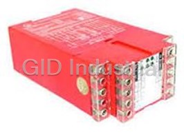


What they say about us
FANTASTIC RESOURCE
One of our top priorities is maintaining our business with precision, and we are constantly looking for affiliates that can help us achieve our goal. With the aid of GID Industrial, our obsolete product management has never been more efficient. They have been a great resource to our company, and have quickly become a go-to supplier on our list!
Bucher Emhart Glass
EXCELLENT SERVICE
With our strict fundamentals and high expectations, we were surprised when we came across GID Industrial and their competitive pricing. When we approached them with our issue, they were incredibly confident in being able to provide us with a seamless solution at the best price for us. GID Industrial quickly understood our needs and provided us with excellent service, as well as fully tested product to ensure what we received would be the right fit for our company.
Fuji
HARD TO FIND A BETTER PROVIDER
Our company provides services to aid in the manufacture of technological products, such as semiconductors and flat panel displays, and often searching for distributors of obsolete product we require can waste time and money. Finding GID Industrial proved to be a great asset to our company, with cost effective solutions and superior knowledge on all of their materials, it’d be hard to find a better provider of obsolete or hard to find products.
Applied Materials
CONSISTENTLY DELIVERS QUALITY SOLUTIONS
Over the years, the equipment used in our company becomes discontinued, but they’re still of great use to us and our customers. Once these products are no longer available through the manufacturer, finding a reliable, quick supplier is a necessity, and luckily for us, GID Industrial has provided the most trustworthy, quality solutions to our obsolete component needs.
Nidec Vamco
TERRIFIC RESOURCE
This company has been a terrific help to us (I work for Trican Well Service) in sourcing the Micron Ram Memory we needed for our Siemens computers. Great service! And great pricing! I know when the product is shipping and when it will arrive, all the way through the ordering process.
Trican Well Service
GO TO SOURCE
When I can't find an obsolete part, I first call GID and they'll come up with my parts every time. Great customer service and follow up as well. Scott emails me from time to time to touch base and see if we're having trouble finding something.....which is often with our 25 yr old equipment.
ConAgra Foods