

 Manufacturers
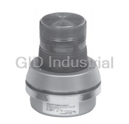
EDWARDS SIGNALING & SECURITY SYSTEMS 5532M-Y6

Description
Edwards Signaling & Security Systems 5532M-Y6 Amplifiers - Remote Speaker/amp 120-250V
Part Number
5532M-Y6
Price
Request Quote
Manufacturer
EDWARDS SIGNALING & SECURITY SYSTEMS
Lead Time
Request Quote
Category
PRODUCTS - 5
Specifications
Components
Captive
Output
up to 100 dB at 10 ft
Volume Control
Individual
Features
- Captive Components
- Corrosion resistant electrostatic heat flowed epoxy finish
- Diode Polarized models
- Individual volume control
- Output up to 100 dB at 10 ft
- RS485 model available
- Suitable for Division 2 Locations
Datasheet

Extracted Text
Installation Instructions for Adaptatone Millennium Tone Generator Series 5540M-485
and Tone Generator with Voice Messaging Series 5540MV-485 and
Speaker/Amplifier, Series 5532
Description and Operation Description and Operation Description and Operation Description and Operation Description and Operation Electrical Specifications Electrical Specifications Electrical Specifications Electrical Specifications Electrical Specifications
Input Board Main Power
Edwards Tone Generator and Speaker/Amplifiers are
Catalog Current (A)
intended for industrial applications where high audible
Number Voltage Current Voltage Standby Tone On
output and microcomputer reliability are required.
Tone Generator
Catalog Series 5532M ending with suffixes -AQ, -24AQ,
-Y6 or -24Y6 are CE Marked. Additionally, the Adaptatone
5540M-485Y6 24V DC 6 mA 125V DC** 0.10 0.21
Millennium series are UL and cUL Listed as Audible Signal
5540MV-485Y6 250V DC** 0.02 0.10
Appliances for use in the following hazardous locations.
120V AC 50/60 Hz 0.10 0.32
240V AC 50/60 Hz 0.10 0.20
Catalog Hazardous Temp.
Speaker/Amplifier - Standard Volume
Number Locations Code
5532M-AQ 24V DC 0.10 0.74
5532M-AQ Class I, Div. 2, Groups A, B, C, D T4 (135C)
24V AC 50/60 Hz 0.10 1.3
5532M-N5 Class II, Div. 2, Groups F, G T5 (100C)
5532M-N5 120V AC 50/60 Hz 0.10 0.36
5532M-Y6 Class III, Div. 1 and 2
5532MHV-AQ 5532M-Y6 125V DC** 0.10 0.21
5532MHV-Y6 250V DC** 0.02 0.10
120V AC 50/60 Hz 0.10 0.32
5540M-485Y6 Class I, Div. 2, Groups A, B, C, D T4 (135C)
240V AC 50/60 Hz 0.10 0.20
5540MV-485Y6 Class II, Div. 2, Groups F, G T5 (100C)
Class III, Div. 1 and 2 5532B-AQ 24V DC 0.06 0.69
36V DC 0.07 0.84
The 5532B Speaker/Amplifiers are UL Listed and CSA Cer-
24V AC 60 Hz 0.26 1.36
tified as Audible Signaling Appliances. 24V AC 50 Hz 0.26 1.36
5532B-N5 120V AC 60 Hz 0.10 0.29
The 5532M-Y6 is additionally UL Listed in a Speaker and
120V AC 50 Hz 0.09 0.29
Amplifier category, when powered with 120V/240V AC
5532B-Y6 125V DC** 0.05 0.16
50/60 Hz, for use in conjunction with the 5541M-Y6 Mil-
250V DC** 0.04 0.10
lennium System Master either for emergency/evacuation,
120V AC 60 Hz 0.10 0.29
non-fire, or for supplementary fire alarm control panel
240V AC 60 Hz 0.11 0.23
accessory applications (see Instructions for 5541M-Y6,
120V AC 50 Hz 0.09 0.29
part 3100471).
240V AC 50 Hz 0.10 0.22
The Tone Generator operates from local power. It accom-
Speaker/Amplifer - High Volume
modates up to four normally-open contacts on its inputs.
5532MHV-AQ 24V DC 0.10 1.5
The tone that sounds in response to an active input is
24V AC 50/60 Hz 0.10 2.3
determined by setting miniature programming switches
5532MHV-Y6 125V DC 0.10 0.39
inside the unit. Figure 19 has switch settings for setting
250V DC 0.02 0.19
tones.
120V AC 50/60 Hz 0.10 0.56
240V AC 50/60 Hz 0.10 0.34
Four tones may be programmed into the Tone Generator
at any time. These tones operate on a pyramid-type pri-
5532BHV-AQ 24V DC 0.06 1.51
ority system. The tone programmed on SW1 overrides
36V DC 0.07 1.98
the tones programmed on SW2, SW3, and SW4. The tone 24V AC 60 Hz 0.26 1.86
on SW2 overrides the tones programmed on SW3 and SW4. 24V AC 50 Hz 0.26 1.86
Likewise, the tone on SW3 overrides the tone programmed
5532BHV-Y6 125V DC 0.05 0.25
on SW4. The tone programmed on SW4 has the lowest
250V DC 0.04 0.23
priority and cannot override any other programmed tone.
120V AC 60 Hz 0.10 0.62
240V AC 60 Hz 0.11 0.33
Speaker/Amplifiers are heavy-duty, stand-alone signaling
120V AC 50 Hz 0.09 0.62
devices that operate from local power and sound a tone
240V AC 50 Hz 0.10 0.33
programmed at the Tone Generator. Speaker direction
and the output level are easily adjustable.
*5532M-Y6 is suitable for use with 120/240V AC Main Power input in conjunction
with the 5541M-Y6 Millennium System Master either for emergency/evacuation,
Specifications Specifications Specifications Specifications Specifications non-fire, or for supplementary fire alarm control panel accessory applications (see
instructions for 5541M-Y6, part 3100471).
Weight - Tone Generator ....................... 6 Pounds (2.7 kg)
Weight - Speaker/Amplifier .................. 9 Pounds (4.1 kg)
Hazardous Locations, UL Standard UL1604
Ambient Temp. ................... +41F to +104F (+5C to +40C)
Non-Hazardous Locations
Variable Ambient Temp. ..... -40F to +151F (-40C to +66C)
Hazardous Locations and Variable Ambient Conditions apply only
where UL listings are accepted and do not apply to either CE confor-
mity or TUV-Rheinland Certification.
P/N 3100346 ISSUE 3 © 2003
CHESHIRE, CT 203-699-3300 FAX 203-699-3365 (CUST. SERV.) 203-699-3078 (TECH SERV.)
Dimensions
5532M 5532MHV
A 8 7/8" 11 1/2"
(225 mm) (292 mm)
B 8 1/4" 9 3/4"
(210 mm) (248 mm)
C 13" 14 1/4"
(330 mm) (362 mm)
Figure 1. Speaker/Amplifier Dimensions
PROGRAMMING
DIPSWITCH
A
B
PGM
TERMINAL
BLOCK TB1
INPUT BOARD
(SEE FIGURE 7)
PROGRAMMING
DIPSWITCH
(SWITCHES SHOWN
IN "OFF" (OPEN)
POSITION)
DIRECTION OF
INCREASING
VOLUME
PROCESSOR BOARD
RECORD
PLAY
RECORD
LED
MICROPHONE
VOICE MODULE
BOARD
VOICE MODULE POTENTIOMETER
FOR VOLUME ADJUSTMENT
Figure 2. Voice Module Board
4. To test the message, press and hold PLAY while in
Recor Recor Recording a ding a ding a V V Voice Message oice Message oice Message
Recor Recording a ding a V Voice Message oice Message
programming mode.
(5540MV (5540MV (5540MV (5540MV (5540MV-485Y6) -485Y6) -485Y6) -485Y6) -485Y6)
NOTE: This will play only the current location.
WARNING WARNING WARNING WARNING WARNING
WARNING WARNING WARNING WARNING WARNING
High voltage is present when product is energized.
High volume may cause harm to personnel in close
proximity.
Four five-second messages (or one twenty-second message)
can be recorded on the voice module unit. Refer to Fig-
5. Adjust the volume as necessary. Set the main volume
ure 2.
using the potentiometer on the main board (Figures
13, 14 and 15) and then set the voice volume using
1. Put switches A and B on the programming dipswitch
the potentiometer on the voice module board (Figure
in the proper position for the message to be recorded
2).
Message Switch Settings
Installation Installation
Installation Installation Installation
Location Start A B
1 0 Sec. ON ON
The Adaptatone may be mounted to any flat surface or
2 5 Sec. OFF ON
may be used as a freestanding unit mounted to a rigid
3 10 Sec. ON OFF
pipe. The Adaptatone must be installed in accordance
4 15 Sec. OFF OFF with the latest edition of the National Electrical Code or
other regulations applicable to the country and locality
of installation and by a trained and qualified electrician.
(Figure 2). For programming a message longer than
five seconds, use Message Location 1.
NOTE: The increased resistance due to long wire runs
needs to be accounted for in sizing wire.
2. Put switch C on the programming dipswitch in the
Consult Applications Engineering for details.
"ON" position for programming mode (Figure 2).
For catalog numbers ending in "AQ," 24V AC power must
3. Press and hold the record button while speaking clearly
be transformer isolated from mains or line power.
into the microphone to record your message. Release
the button when recording is complete.
P/N 3100346 ISSUE 3 PAGE 2
d. Connect incoming power to wire leads using a
CAUTION CAUTION CAUTION
CAUTION CAUTION
butt splice or other method listed, certified, or
otherwise approved by local authorities. Leads
During installation, care must be taken so that components
are black and white.
on the printed circuit board are not damaged.
e. Optional. Connect external 24V DC battery (not
1. Mount Adaptatone as shown in Figure 3.
supplied) in series with separate diode assembly
part 2600010 (supplied) to TB1 terminals 3 and 4
a. Flat Surface Mounting. Secure unit to
on the main board as shown in Figures 4 and 5
mounting surface using the (4) mounting holes in
and marked on the diode assembly.
the mounting plate on the rear of the box. Use
the #10 x 3" (76 mm) wood screws (furnished loose)
NOTE: Terminal Block TB1 can be unplugged from the
or other hardware (not supplied) suitable for the
main board to complete wiring as shown in
mounting surface.
Figure 4.
b. Rigid Pipe Mounting. Loosen the (4) cover screws
4. Wire the 5532M series speaker/amplifier as follows
from the signal box and lift off signal box cover.
referring to Figures 6, 7 and 8:
NOTE: Cover screws are captive. Do not remove from
a. Connect green and yellow striped earth-ground
cover.
wires to earth-ground.
Remove the center knockout in lower wall of box
b. See Figure 8. Connect audio output (+) from the
and mount box to a 1/2" (12.7 mm) conduit pipe
main board of the tone generator to the AUD (+)
using suitable connector.
terminal on the Speaker/Amplifier Audio Coupler
Board. Connect audio output (-) from the main
2. Install wires through a knockout hole in the bottom
board of the tone generator to the AUD (-) terminal
of the box from a raceway that is, with its connections
on the Speaker/Amplifier Audio Coupler Board.
to the 1/2" (12.7 mm) conduit knockout hole, approved
Use shielded cable and connect braid or drain to
for the same degree of protection and enclosure type
earth-ground wire lead of 5540 Tone Generator.
needed by the application. Use the provided plastic
tie-wrap, on the barrier to the electronics, to separate
c. Connect incoming power to wire leads using a
incoming power leads from signal and tone initiating
butt splice or other method listed, certified, or
leads, per NEC (Figures 4, 5 and 6).
otherwise approved by local authorities. Leads
are both black for -AQ and -N5 models and are
WARNING WARNING WARNING WARNING WARNING
black for line and white for neutral for -Y6 models.
To prevent fire and shock, wire the Adaptatone only as
e. Optional. Connect external 24V DC battery (not
described in this installation instruction.
supplied) in series with separate diode assembly
part 2600010 (supplied) to TB1 terminals 3 and 4
3. Wire the 5540M Series Tone Generator referring to
on the main board as shown in Figure 7 and
Figures 4 and 5 as follows:
marked on the diode assembly.
a. Connect green and yellow-striped earth-ground NOTE: Terminal Block TB1 can be unplugged from the
wires to earth-ground. main board to complete wiring as shown in
Figure 7.
b. Connect the RS485 wires to terminals +TX/RX and
-TX/RX on the RS485 COMM board (Figure 5). 5. Wire to the 5532B series speaker/amplifier as follows
and referring to Figures XX:
c. If using the optional MR201/C relay, connect the
relay to +RELAY and -RELAY on the RS485 COMM a. Connect green earth-ground wire of speaker/
board (Figure 5). amplifier and green and yellow striped earth-
ground wires on tone generator to earth-ground.
b. Connect audio output (+) from the main board of
the tone generator to the Tone In terminal 9 (+) in
the Speaker/Amplifier. Connect audio output (-)
from the main board of the tone generator to the
Speaker
Tone In Termal 10 (-) in the Speaker/Amplifier.
d. For 5532B-AQ, 5532BDV2-AQ and 5532BHV-AQ
models, connect power source to the Speaker/
Amplifiers at TS2. Polarity must be observed for
Large star nut to
adjust speaker
DC models.
direction
Signal Box Signal Box
e. For 5532B-Y6, 5532BDV2-Y6, 5532BHV-Y6, and
5532B-N5 models, connect incoming power to wire
(4) Cover (4) Cover
screws screws
leads from power supply. For -Y6 models using a
(4) Collar (4) Collar DC source, black wire is positive and white is
gaskets gaskets
negative and polarity must be observed. For AC
Raceway and connections
source, black is line and white is neutral.
(not supplied)
to the 1/2" (12.7 mm)
knockout hole
g. Optional. Wire 24V DC battery backup to TS1-1
(4) #10 x 3" (76 mm)
screws or other hardware
and TS1-2 of the Speaker/Amplifier per Figure 18
suitable for the mounting surface
and connect 24V DC battery backup in series with
diode assembly part 2600010 (supplied) to TB1
Figure 3. Adaptatone Mounting
PAGE 3 P/N 3100346 ISSUE 3
terminals 3 and 4 on the main board of the tone
WARNINGS WARNINGS WARNINGS WARNINGS WARNINGS
generator per Figure 7. Polarities must be observed.
Ensure that the (4) collar gaskets, part number P-041930-
0362, are in place on each cover screw before securing the
WARNINGS WARNINGS WARNINGS WARNINGS WARNINGS
signal box cover.
HIGH VOLTAGE is present when product is energized. High
volume may cause harm to personnel in close proximity.
When securing cover, start screws by hand, making sure
they are threaded into tapped holes in housing bosses
6. Adjust volume level, if desired, by turning
before securing with a screwdriver. Torque signal box cover
potentiometer located on the main board (Figures 13,
screws to a minimum of 20 in-lbs. This ensures the
14, 15 and 18) and on voice board (Figure 2).
required tight fit.
8. Tightly secure the signal box cover using (4) retained
WARNING WARNING
WARNING WARNING WARNING
cover screws.
To ensure integrity of the Adaptatone assembly when
9. Torque signal box cover screws to a minimum of 20
adjusting the speaker direction, make sure threads in the
in-lbs.
enclosure remain fully engaged and do not turn speaker
more than 360 degrees from the original factory installed
10. Verify operability.
position.
Maintenance and Maintenance and T Test est
Maintenance and Maintenance and Maintenance and T T Test est est
7. To adjust speaker direction, loosen large star nut
(Figure 3) and turn speaker to the approximate desired
position. Retighten nut and turn speaker slightly
WARNING WARNING WARNING WARNING WARNING
clockwise until locked into place.
Ensure that power is disconnected before cleaning inside of
unit.
WARNING WARNING WARNING WARNING WARNING
To ensure integrity of the enclosure: Ensure the cover
Examine the unit semi-annually for accumulation of dirt.
gasket, part number P-007549-0069, is adhered into
Clean if necessary.
groove at cover perimeter before replacing the signal box
The Adaptatone should be tested annually or as required
cover.
by the authority having jurisdiction to ensure continuous
service.
Protocol Protocol Protocol Protocol Protocol
1.0 Setting Unit Address and Network Baud Rate
1.1 Locate the 8-position dip switch, S1, on the top edge of the RS485 COMM board (Figure 6).
1.2 Unit address range is 00-1F hex. (00-31 decimal). Refer to Table 2.2 for unit address configuration. Set S1
positions 1-5 for the desired unit address configuration.
Table 2.2 Unit Address Switch Configuration
Unit Address S1-1 S1-2 S1-3 S1-4 S1-5
Hex Decimal
00 00 OPEN OPEN OPEN OPEN OPEN
01 01 CLOSED OPEN OPEN OPEN OPEN
02 02 OPEN CLOSED OPEN OPEN OPEN
03 03 CLOSED CLOSED OPEN OPEN OPEN
04 04 OPEN OPEN CLOSED OPEN OPEN
05 05 CLOSED OPEN CLOSED OPEN OPEN
06 06 OPEN CLOSED CLOSED OPEN OPEN
07 07 CLOSED CLOSED CLOSED OPEN OPEN
08 08 OPEN OPEN OPEN CLOSED OPEN
09 09 CLOSED OPEN OPEN CLOSED OPEN
0A 10 OPEN CLOSED OPEN CLOSED OPEN
0B 11 CLOSED CLOSED OPEN CLOSED OPEN
0C 12 OPEN OPEN CLOSED CLOSED OPEN
0D 13 CLOSED OPEN CLOSED CLOSED OPEN
0E 14 OPEN CLOSED CLOSED CLOSED OPEN
0F 15 CLOSED CLOSED CLOSED CLOSED OPEN
P/N 3100346 ISSUE 3 PAGE 4
Table 2.2 Unit Address Switch Configuration (Cont'd)
Unit Address S1-1 S1-2 S1-3 S1-4 S1-5
Hex Decimal
10 16 OPEN OPEN OPEN OPEN CLOSED
11 17 CLOSED OPEN OPEN OPEN CLOSED
12 18 OPEN CLOSED OPEN OPEN CLOSED
13 19 CLOSED CLOSED OPEN OPEN CLOSED
14 20 OPEN OPEN CLOSED OPEN CLOSED
15 21 CLOSED OPEN CLOSED OPEN CLOSED
16 22 OPEN CLOSED CLOSED OPEN CLOSED
17 23 CLOSED CLOSED CLOSED OPEN CLOSED
18 24 OPEN OPEN OPEN CLOSED CLOSED
19 25 CLOSED OPEN OPEN CLOSED CLOSED
1A 26 OPEN CLOSED OPEN CLOSED CLOSED
1B 27 CLOSED CLOSED OPEN CLOSED CLOSED
1C 28 OPEN OPEN CLOSED CLOSED CLOSED
1D 29 CLOSED OPEN CLOSED CLOSED CLOSED
1E 30 OPEN CLOSED CLOSED CLOSED CLOSED
1F 31 CLOSED CLOSED CLOSED CLOSED CLOSED
1.3 RS485 COMM supports 1200, 2400, 9600 and 19200 baud rate using 8 data bits and one stop bit. Parity is not
supported. Refer to Table 1.3 for Baud Rate switch configuration. Set S1 positions 6-7 for the desired Baud
Rate configuration.
Table 1.3 Network Baud Rate setting
Baud Rate S1-6 S1-7
1200 OPEN OPEN
2400 CLOSED OPEN
9600 OPEN CLOSED
19200 CLOSED CLOSED
1.4 Set 100-ohm termination resistor (if required). Network termination is required if the unit is located at the
beginning or end of the network bus. Termination reduces unwanted reflections caused by data signal
propagation due to long wire runs. Refer to Table 1.4 for switch configuration. Set S1 position 8 for network
termination if required.
Table 1.4 Termination setting
Termination (100 ohms) S1-8
Enabled CLOSED
Disabled OPEN
2.0 Messaging Format
2.1 The RS485 COMM utilizes the Edwards SigNet ASCII protocol for data messaging. Each unit is capable of
consuming and/or producing messages from the master controller. SigNet message format is illustrated
below.
Frequently asked questions
What makes Elite.Parts unique?

What kind of warranty will the 5532M-Y6 have?
Which carriers does Elite.Parts work with?
Will Elite.Parts sell to me even though I live outside the USA?
I have a preferred payment method. Will Elite.Parts accept it?
Why buy from GID?

Quality
We are industry veterans who take pride in our work

Protection
Avoid the dangers of risky trading in the gray market

Access
Our network of suppliers is ready and at your disposal

Savings
Maintain legacy systems to prevent costly downtime

Speed
Time is of the essence, and we are respectful of yours
Related Products
Edwards Signaling and Security Systems 51A-E1 Amber AdaptaBeacon Flashing Light with Horn 24 watts 1...
Beacon Light
Edwards Signaling and Security Systems 51A-G5-20W Amber AdaptaBeacon Flashing Light with Horn 20 wat...
Edwards Signaling and Security Systems 51A-N5-40W Amber AdaptaBeacon Flashing Light with Horn 40 wat...
Edwards Signaling and Security Systems 51B-E1 Blue AdaptaBeacon Flashing Light with Horn 24 watts 12...
Edwards Signaling and Security Systems 51B-G1 Blue AdaptaBeacon Flashing Light with Horn 24 watts 24...
Request a Quote

The quote request has been received
Close

Facing challenges or have inquiries? Feel free to contact us!
Call Us +1-469-283-2440
What they say about us
FANTASTIC RESOURCE
One of our top priorities is maintaining our business with precision, and we are constantly looking for affiliates that can help us achieve our goal. With the aid of GID Industrial, our obsolete product management has never been more efficient. They have been a great resource to our company, and have quickly become a go-to supplier on our list!
Bucher Emhart Glass
EXCELLENT SERVICE
With our strict fundamentals and high expectations, we were surprised when we came across GID Industrial and their competitive pricing. When we approached them with our issue, they were incredibly confident in being able to provide us with a seamless solution at the best price for us. GID Industrial quickly understood our needs and provided us with excellent service, as well as fully tested product to ensure what we received would be the right fit for our company.
Fuji
HARD TO FIND A BETTER PROVIDER
Our company provides services to aid in the manufacture of technological products, such as semiconductors and flat panel displays, and often searching for distributors of obsolete product we require can waste time and money. Finding GID Industrial proved to be a great asset to our company, with cost effective solutions and superior knowledge on all of their materials, it’d be hard to find a better provider of obsolete or hard to find products.
Applied Materials
CONSISTENTLY DELIVERS QUALITY SOLUTIONS
Over the years, the equipment used in our company becomes discontinued, but they’re still of great use to us and our customers. Once these products are no longer available through the manufacturer, finding a reliable, quick supplier is a necessity, and luckily for us, GID Industrial has provided the most trustworthy, quality solutions to our obsolete component needs.
Nidec Vamco
TERRIFIC RESOURCE
This company has been a terrific help to us (I work for Trican Well Service) in sourcing the Micron Ram Memory we needed for our Siemens computers. Great service! And great pricing! I know when the product is shipping and when it will arrive, all the way through the ordering process.
Trican Well Service
GO TO SOURCE
When I can't find an obsolete part, I first call GID and they'll come up with my parts every time. Great customer service and follow up as well. Scott emails me from time to time to touch base and see if we're having trouble finding something.....which is often with our 25 yr old equipment.
ConAgra Foods