

 Manufacturers
ECS MB694A
Description
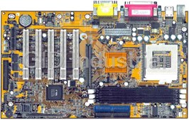
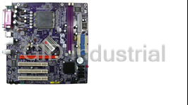
ECS MB694A - Single-Board CPU | Socket 370 | VIA694X & 686B Chipset | 5x PCI Slots
Part Number
MB694A
Price
Request Quote
Manufacturer
ECS
Lead Time
Request Quote
Category
MOTHERBOARDS
Specifications
Board Type
ATX
Features
- - 4xAGP Graphics Adapter Slot
- - AC 97 Audio Codec
- - Expansion Options
- - Inexpensive Memory
- - Integrated I/O
- - Keyboard Power on Feature
- - Programmable Firmware
- - Value-class Processors
- - VIA North Bridge Chipset
- - VIA South Bridge Chipset
Datasheet

Extracted Text
Important Information
Copyright
This publication, including all photographs, illustrations and
software, is protected under international copyright laws, with all
rights reserved. Neither this manual, nor any of the material con-
tained herein, may be reproduced without the express written
consent of the manufacturer.
Version 1.0
Disclaimer
The information in this document is subject to change without
notice. The manufacturer makes no representations or warran-
ties with respect to the contents hereof and specifically disclaims
any implied warranties of merchantability or fitness for any par-
ticular purpose. Further, the manufacturer reserves the right to
revise this publication and to make changes from time to time in
the content hereof without obligation of the manufacturer to no-
tify any person of such revision or changes.
i
Trademark Recognition
Microsoft, MS-DOS and Windows are registered trademarks of
Microsoft Corp.
MMX, Pentium, Pentium-II, Pentium-III, Celeron are registered
trademarks of Intel Corporation.
Other product names used in this manual are the properties of
their respective owners and are acknowledged.
Federal Communications Commission (FCC)
This equipment has been tested and found to comply with the lim-
its for a Class B digital device, pursuant to Part 15 of the FCC
Rules. These limits are designed to provide reasonable protection
against harmful interference in a residential installation. This
equipment generates, uses, and can radiate radio frequency en-
ergy and, if not installed and used in accordance with the
instructions, may cause harmful interference to radio communica-
tions. However, there is no guarantee that interference will not
occur in a particular installation. If this equipment does cause
harmful interference to radio or television reception, which can be
determined by turning the equipment off and on, the user is en-
couraged to try to correct the interference by one or more of the
following measures:
Reorient or relocate the receiving antenna.
Increase the separation between the equipment and the
receiver.
Connect the equipment onto an outlet on a circuit differ-
ent from that to which the receiver is connected.
Consult the dealer or an experienced radio/TV technician
for help.
Shielded interconnect cables and a shielded AC power cable
must be employed with this equipment to ensure compliance
with the pertinent RF emission limits governing this device.
Changes or modifications not expressly approved by the sys-
tem’s manufacturer could void the user’s authority to operate the
equipment.
ii
Declaration of Conformity
This device complies with part 15 of the FCC rules. Operation is
subject to the following conditions:
This device may not cause harmful interference, and
This device must accept any interference received, in-
cluding interference that may cause undesired operation.
Canadian Department of Communications
This class B digital apparatus meets all requirements of the Ca-
nadian Interference-causing Equipment Regulations.
Cet appareil numérique de la classe B respecte toutes les exi-
gences du Réglement sur le matériel brouilieur du Canada.
iii
About the Manual
The manual consists of the following chapters:
Introduction
Use the Introduction Chapter to learn about the features of the
mainboard, and verify the checklist of items that are shipped
with the package.
Installation
Use the Installation Chapter to learn how to install the main-
board and get your system up and running.
Setup
Use the Setup Chapter to configure the mainboard for optimum
performance.
Software
Use the Software Chapter to learn how to install the software
drivers and support programs that are provided with this main-
board.
iv
Contents
Important Information i
Copyright i
Disclaimer i
Trademark Recognition ii
Federal Communications Commission (FCC) ii
Declaration of Conformity iii
Canadian Department of Communications iii
About the Manual iv
CHAPTER 1: INTRODUCTION 1
Welcome 1
Checklist 2
Recommendations 3
Features 4
CHAPTER 2: INSTALLATION 7
Quick Installation Table 7
Quick Jumper Setting Reference 8
Before You Begin 12
Static Electricity 12
Choosing a Case 12
How to Set Jumpers 13
Preparing the Mainboard 14
Mainboard Guide 14
I/O Ports Side View 16
Check the Jumper Settings 17
Installing the Mainboard in a Case 21
Connecting Internal Components 22
Installing Other Hardware 24
Installing the Processor 24
Install the Memory Modules 26
Installing a Hard Disk Drive and CD-ROM 28
Installing a Floppy Diskette Drive 31
Using the Expansion Slots 32
v
Add-in Card Options 35
Making External Connections 37
External Connector Color Coding 38
CHAPTER 3: SETUP 39
About the Setup Utility 39
Entering the Setup Utility 40
BIOS Navigation Keys 41
Using BIOS 42
How to Flash a New BIOS 43
Standard CMOS Setup Option 44
Advanced CMOS Setup Option 47
Advanced Chipset Features Option 51
Integrated Peripherals Option 55
Power Management Setup Option 59
PNP/PCI Configuration Option 65
PCI Health Status Option 67
Frequency Control Option 68
Load Fail-Safe Defaults Option 69
Load Optimized Defaults Option 69
Set Supervisor and User Passwords Options 70
Save & Exit Setup Option 71
Exit Without Saving Option 71
CHAPTER 4: SOFTWARE 73
Driver Folders 73
Utility Folders 73
Driver Installation Notes 74
IDE 74
Audio 74
Utility Folder Installation Notes 74
vi
Chapter 1: Introduction
Chapter 1: Introduction
Welcome
Congratulations on purchasing MB694A mainboard. The
MB694A mainboard is an ATX mainboard that uses a 4-layer
printed circuit board and measures 304 mm x 190 mm. The
mainboard features a Socket 370 that accommodates PPGA
Celeron, FC-PGA Pentium III, and Cyrix III processors that sup-
port frontside bus (FSB) speeds up to 133 MHz.
This MB694A uses the VIA family chipset and features the AC
97 audio codec. The mainboard delivers high-level performance
with a 4xAGP (Accelerated Graphics Port) slot and two PCI Bus
Master Ultra DMA (UDMA) ports that support up to four ATAPI (AT
Attachment Packet Interface) devices. The PCI IDE also supports
PIO Mode 3 and 4, UDMA33/66 IDE, and an ATAPI CD-ROM.
The mainboard accommodates PC 100/133 SDRAM (Synchro-
nous DRAM) up to 1.5 GB using three 3.3V unbuffered DIMM
modules. The MB694A also has a full set of I/O ports, such as dual
channel IDE interfaces, a floppy controller, two FIFO serial port
connectors, an EPP/ECP-capable bi-directional parallel port con-
nector, a dual USB (Universal Serial Bus) connector, and PS/2
keyboard and mouse connectors.
One AGP slot, five PCI local bus slots, and one audio modem riser
(AMR) slot provide expandability for add-on peripheral cards.
1
This chapter contains the following information:
Checklist comprises a list of the standard and optional
components that are shipped with this mainboard
Recommendations lists some Do’s and Don’ts from the
manufacturer to help ensure reliability and performance
from this product
Features highlights the functions and components that
make this one of the best value mainboards on the mar-
ket
Checklist
Compare the contents of your mainboard package with the stan-
dard checklist below. If any item is missing or appears damaged,
please contact the vendor of your mainboard package.
Standard Items
One mainboard
One diskette drive ribbon cable and bracket
One IDE drive ribbon cable and bracket
This user’s manual
Software support CD-ROM disc
2
Recommendations
This mainboard automatically determines the CPU clock fre-
quency and system bus frequency for the kind of processor that
you install. You may be able to change these automatic settings
by making changes to jumpers on the mainboard, or changing
the settings in the system Setup Utility. We strongly recommend
that you do not overclock the mainboard to run processors or
other components faster than their rated speed.
Warning: Overclocking components can adversely affect the reliabil-
ity of the system and introduce errors into your system. Overclocking
can permanently damage the mainboard by generating excess heat
in components that are run beyond the rated limits.
Components on this mainboard can be damaged by discharges
of static electricity. Handle the board carefully holding it by the
edges. Don’t flex or stress the circuit board. Keep the board in
its static-proof packing until you are ready to install it. Follow the
static guidelines given at the beginning of Chapter 2.
3
Features
The key features of this mainboard are the wide range of proc-
essors that can be installed, and the high level of integration.
Value-class Processors
Functioning as a platform for a value PC, the MB694A features a
Socket 370 that accommodates PPGA Celeron, Pentium III, and
Cyrix III processors. The MB694A supports 66/100/133 MHz
FSB speeds.
VIA North Bridge Chipset
This board features the VIA VT82C694X NB (North Bridge)
chipset, enabling synchronous and asynchronous frequency op-
eration between the processor and the memory over a wide
frequency range. The NB chipset is optimized for Pentium III
processors at 66/100/133 MHz Front Side Bus (FSB) frequency
and supports 32-bit processor bus addressing.
The integrated DRAM controller supports up to four double-
sided DIMMs consisting of EDO, SDRAM, or VCM SDRAM. The
NB chipset provides SDRAM with 64-bit data access.
The AGP interface is AGP specification Rev 2.0 compliant, and
supports 2x/4x/4x 3.3/1.5V devices. The PCI bus interface com-
plies with PCI Rev. 2.1, and supports 3.3V and power supplies.
Five PCI bus masters are supported in addition to the host and
PCI-to-ISA I/O bridge.
VIA South Bridge Chipset
The VIA VT82C686A SB (South Bridge) chipset comes in a 352-
pin BGA package. The PCI to ISA Bridge has an integrated ISA
bus controller with integrated DMA, timer, and interrupt control-
lers.
The Real Time Clock features extended 256 byte CMOS RAM
and a day and month alarm for the ACPI (Advanced Configura-
tion and Power Interface).
4
There is an integrated USB controller with a built-in root hub and
four function ports. The integrated Ultra DMA-33/66 master
mode EIDE controller with enhanced PCI bus commands.
The UltraDMA-33/66 Master Mode PCI EIDE controller features
dual channel master mode PCI supporting Enhanced IDE (EIDE)
devices and employ transfer rates up to 33 MB/sec to cover PIO
mode 4, multi-word DMA mode 2 drives, and UltraDMA-33 inter-
face. The SB chipset also supports ATAPI compliant devices
including DVD devices and four USB 1.1 ports for serial trans-
fers at 12 or 1.5 Mbits/sec.
The integrated super IO controller supports two serial ports, an
IR port, parallel port, and floppy disk controller functions. There
is also system monitor support, providing system feedback of
voltage, temperature, and fan speed conditions.
Inexpensive Memory
The board has three DIMM sockets for the installation of 168-pin,
3.3V non-buffered DIMM memory modules. The DIMM memory
modules can be SDRAM or VCM memory chips.
4xAGP Graphics Adapter Slot
The MB694A includes a 4xAGP slot that provides four times the
bandwidth of the original AGP specification. AGP technology
provides a direct connection between the graphics sub-system
and the processor so that the graphics do not have to compete
for processor time with other devices on the PCI bus.
The AGP design allows the graphics controller to use part of the
main memory when it needs it, for example, in handling the very
large texture maps required by virtual reality and 3D video
games and applications.
AC 97 Audio Codec
The AC 97 Audio codec is compliant with the AC 97 2.1 specifi-
cation, and supports 18-bit ADC (Analog Digital Converter) and
DAC (Digital Analog Converter) resolution as well as 18-bit ste-
reo full-duplex codec with independent and variable sampling
rates. Further features include support for four analog line-level
stereo inputs.
5
Expansion Options
Five 32-bit PCI slots, an AGP slot, and an AMR slot provide
plenty of expansion potential. The MB694A PCI slots support Ul-
tra DMA33/66 bus mastering with transfer rates up to 33/66
MB/sec.
Integrated I/O
The mainboard has a full set of I/O ports and connectors. The
I/O template on the backplane includes two PS/2 ports for
mouse and keyboard, one serial port, one VGA port, one parallel
port, one MIDI/game port, two USB ports with an onboard
header providing two extra USB ports, and audio jacks for mi-
crophone, line-in and line-out. The board includes two PCI IDE
channels and a floppy disk drive interface.
Keyboard Power on Feature
Using the system BIOS setup program, you can configure the
system to turn on using a keyboard-typed password. A green
keyboard is not required.
Programmable Firmware
The mainboard includes Award BIOS that allows BIOS setting of
CPU parameters. This fully programmable firmware enhances
the system features and allows users to set such items as power
management, CPU and memory timing, and modem wake-up
alarms. The firmware can also be used to set parameters for dif-
ferent processor clock speeds so that you don’t need to change
mainboard jumpers and switches.
This concludes Chapter 1. The next chapter will cover installing
and building a working system.
6
Chapter 2: Installation
Chapter 2: Installation
Quick Installation Table
This chapter explains how to successfully install the mainboard
into a computer case and build a working system. The installa-
tion procedure is as follows:
Quick Jumper Provides a quick reference for the jumper
Setting settings on this mainboard.
Reference
Before you Provides advice on choosing a case,
Begin avoiding static electricity damage, and set-
ting jumpers.
Preparing the Provides a guide to the mainboard and I/O
Mainboard port locations, full details on the jumper
settings, and advice on installing the main-
board in the system case.
Installing Other Provides guidance on installing essential
Hardware hardware: processor, memory, hard disk
drive, CD-ROM, floppy disk drive, and ex-
pansion cards.
Making Provides advice on using the external I/O
External ports to install peripheral devices such as a
Connections keyboard, a monitor, a mouse, a printer,
and loudspeakers.
7
Quick Jumper Setting Reference
If you are familiar with most of the material in this chapter, you
can prepare the mainboard for installation by using this quick
reference to set the jumpers. A detailed description of the
jumper setting appears later in this chapter.
JP1: Clear CMOS jumper
Use this jumper to clear the contents of the CMOS memory.
Function Jumper Setting
JP1
Normal operation Short pins 1-2
1 2 3
Clear CMOS Short pins 2-3
Note: Disconnect all AC power to the computer before clearing
the CMOS.
JP2: Keyboard power on/off jumper
Use this jumper to enable the keyboard to power on the com-
puter. You must also enable this function in the BIOS Setup
Utility. Refer to Chapter 3.
Function Jumper Setting
JP2
Disable Short pins 1-2
1 2 3
Enable Short pins 2-3
Note: When enabling the keyboard power on/off function, ensure
that the 5 VSB power supply is more than 720 mA.
JP3: BIOS flash protection jumper
Use this jumper to disable and enable BIOS flashing. Disable
the jumper if you are going to flash the system BIOS.
Function Jumper Setting
JP3
Disable Short pins 1-2
1 2 3
Enable Short pins 2-3
8
JP4: Onboard codec/AMR slot select jumper
Use this jumper to enable either the onboard codec or the AMR
slot (AMR1).
Function Jumper Setting
JP4
Onboard codec Short pins 1-2
1 2 3
AMR slot Short pins 2-3
JP5: AMR Master/Slave select jumper
Use this jumper to define the AMR codec mode to avoid conflict
with the onboard AC 97 codec.
Function Jumper Setting
JP5
Slave AMR Short pins 1-2
1 2 3
Master AMR Short pins 2-3
JP6: CPU frequency select jumper
Use this jumper to force a CPU that has a 66 MHz frontside bus
(FSB) to run at a 100 MHz FSB speed.
Function Jumper Setting
JP6
Normal operation Short pins 1-2
1 2 3
Force a 66 MHz FSB to Short pins 2-3
run at 100 MHz FSB
Note: The CPU speed is determined by the CPU Host/PCI Clock
speed multiplied by the CPU Clock Ratio. Refer to the Frequency
Control Option in Chapter 3 for more information.
Forcing the CPU to run at a higher clock speed then it was rated
for is called overclocking and is not recommended.
9
JP7: CPU frequency select jumper
Use this jumper to force a CPU that has a 100 MHz frontside
bus (FSB) to run at a 133 MHz FSB speed.
Function Jumper Setting
JP7
Normal operation Short pins 1-2
1 2 3
Force a 100 MHz FSB to Short pins 2-3
run at 133 MHz FSB
Note: The CPU speed is determined by the CPU Host/PCI Clock
speed multiplied by the CPU Clock Ratio. Refer to the Frequency
Control Option in Chapter 3 for more information.
Forcing the CPU to run at a higher clock speed then it was rated
for is called overclocking and is not recommended.
JP500: Set ROM voltage jumper
This jumper is used to select the voltage for the onboard ROM.
DO NOT make any adjustments to this jumper!
JP501: Set ROM memory size jumper
This jumper is used to select the memory size for the onboard ROM.
DO NOT make any adjustments to this jumper!
Important! Do not make any changes to JP500 or JP501. These
jumpers are set at the factory.
10
PANEL1: Panel connectors for switches and indicators
Use the panel connector to implement the switches and indica-
tors on your system case.
Panel connectors for switches and indicators
PANEL1
Function Pins
Power switch 22, 23
23
Hard disk LED Indicator +20, -21
Power Switch 22-23
Empty pin 19
HDD LED 20-21
Speaker +15, -16, 17, 18
Empty pin 14
Speaker 15-16-17-18
Reset switch 12, -13
Empty pins 10, 11
Green LED indicator +7, +8, -9
Reset Switch 12-13
Empty pin 6
Sleep switch 4, -5
Green LED 7-8-9
Power LED indicator +1, +2, -3
Sleep Switch 4-5
Power LED 1-2-3
1
Note: The plus sign (+) indicates a pin which must be connected
to a positive voltage.
11
PANEL1
Before You Begin
Before you begin to install your mainboard, take care not to
damage the product from static electricity. Ensure too that you
are installing the mainboard into a suitable case.
Static Electricity
In adverse conditions, static electricity can accumulate and dis-
charge through the integrated circuits and silicon chips on this
product. These circuits and chips are sensitive and can be per-
manently damaged by static discharge.
• If possible, wear a grounding wrist strap clipped to a
safely grounded device during the installation.
• If you don’t have a wrist strap, discharge any static by
touching the metal case of a safely grounded device be-
fore beginning the installation.
• Leave all components inside their static-proof bags until
they are required for the installation procedure.
• Handle all circuit boards and electronic components
carefully. Hold boards by the edges only. Do not flex or
stress circuit boards.
Choosing a Case
The mainboard complies with the specifications for the Micro
ATX system case. Some features on the mainboard are imple-
mented by cabling connectors on the mainboard to indicators
and switches on the system case. Ensure that your case sup-
ports all the features required. The mainboard can support one
or two floppy diskette drives and four enhanced IDE drives. En-
sure that your case has sufficient power and space for all the
drives that you intend to install.
The mainboard has a set of I/O ports on the rear edge. Ensure
that your case has an I/O template that supports the I/O ports
and expansion slots.
12
How to Set Jumpers
A jumper consists of two or more pins mounted on the main-
board. Some jumpers might be arranged in a series with each
pair of pins numbered differently. Jumpers are used to change
the electronic circuits on the mainboard. When a jumper cap (or
shunt) is placed on two jumper pins, the pins are SHORT. If the
jumper cap is removed (or placed on just a single pin), the pins
are OPEN.
This illustration shows a 2-pin jumper.
When the jumper cap is placed on
both pins, the jumper is SHORT. If
you remove the jumper cap, or place
the jumper cap on just one pin, the
jumper is OPEN.
Open
Short
This illustration shows a 3-pin jumper.
The jumper cap is placed on pins 2
and 3, so this jumper setting is
SHORT PINS 2-3.
This illustration shows the same 3-pin
jumper. The jumper cap is placed on
pins 1 and 2, so this jumper setting is
SHORT PINS 1-2.
In this manual, all the jumper illustrations clearly show the pin
numbers. When you are setting the jumpers, make sure that the
jumper caps are placed on the correct pins to select the function
or feature that you want to enable or disable.
13
Preparing the Mainboard
Mainboard Guide
Use the following illustration and key to identify the components
on your mainboard.
DIMM 2
DIMM 3
DIMM 1
CPUFAN1 PWRFAN1
JP2
CPUFAN1
PWRFAN1
1 JP2
JP7
1 JP7
1 JP6
JP6
Socket 370
IDE1
IDE2
ATX1
CD1
CD2
CD2
CD1
AGP1
AGP1
PCI1
PCI1
PCI2
PCI2
PANEL1
PCI3
PCI3
JP5
PCI4
PCI4
1
JP5
JP1
PCI5
1
JP1
1
3V
PCI5
BT1
+ JP501
JP500
JP3
JP501 1
1
JP500
AMR1
JP4
JP4 FDD1
AMR1
1
FDD1
WOL1 WOM1 USB2 1 SIR1
USB2
AN1PWRFJP2AN1DIMM1DIMMJP15JP33PWRFAN1JP2CPUFAN1CPUFAN1JP15JP3JP4JP5 WOL1 WOM1 SIR1
CD1J23VVGACD2CD1PWRFCD2J3A1AMR1JP14LTI1MR1ATX1PBT1+BT1CI1PJP1PCI1PCI2PPGAAGP1CPCI2AGP11UFANCPULOCKFREESIR1SIR1FAN11JP18JJP1WWOP17JP16IDEFDDOM1WUSB2M1WOL1PJP9JP10JP4JP5ANE11JP7JP8IDEOL1L1J2CD1CD1J3CD23V+VGA1AATCD2BTBT1AMR1JP14LTI1MR1PCX11JP1PPAGI1PCI2AGP1PCI1PCI2P1GA1LOCKFREESISIR1R1JP1JP18JFDOM1WUSB2P17JP16POM1WOL1JP9JP10IDE1IAD1WJP7JP8OL1NEL1DW
14
LTI1J1ATX1JP6VID1VID2VID3VID4VID5
PANEL1DIMM1DIMM2DIMM3IDE1IDE2DIMM1DIMM2DIMM3FDD1LTI1J1ATX1VID5JPVID1VID2VID3VID46
PANEL1IDE1IDE2FDD1
ATX1
DIMM1
DIMM2
DIMM3
IDE1
IDE2
JP3 PANEL1
Key to Mainboard Components
Component Description
JP2 Keyboard power on/off jumper
CPUFAN1 Power connector for CPU cooling fan
DIMM 1, 2, 3 Three slots for 168-pin DRAM memory module
PWRFAN1 Power connector for case cooling fan
JP6, 7 CPU frequency select jumper
Socket 370 PGA 370 CPU socket
ATX1 Connector for ATX power supply
CD1 Audio connector for CD-ROM/DVD drive
CD2 Auxiliary connector for CD-ROM/DVD drive
IDE1, IDE2 Primary and secondary IDE channels
AGP1 Accelerated Graphics Port slot
PCI1 ~ PCI5 Five 32-bit PCI slots
JP5 Select AMR as Master/Slave jumper
BT1 3 volt battery for realtime clock
JP4 On-board codec or AMR slot select jumper
AMR1 Audio modem riser (AMR) slot
WOL1 Connector for LAN wake up
WOM1 Connector for modem wake up
FDD1 Connector for floppy disk drives
JP1 Clear the system CMOS jumper
PANEL1 Panel connector for switches and indicators
JP3 BIOS flash protection jumper
USB2 Connector for USB port
SIR1 SIR connector for infrared
JP500 Select ROM type jumper
JP501 Select ROM memory jumper
Important! Do not make any changes to JP500 or JP501. These
jumpers are set at the factory.
15
I/O Ports Side View
Parallel port (LPT1)
PS/2
Game port
mouse
PS/2 USB Serial port Serial port
Microphone
keyboard ports COM 1 COM 2
Line-in
Line-out
Key to I/O Ports
Component Description
PS/2 mouse PS/2 port for pointing device (upper port)
PS/2 keyboard PS/2 port for keyboard (lower port)
USB ports Two stacked Universal Serial Bus ports
LPT1 External parallel port
COM1 External serial port COM 1
COM2 External serial port COM 2
Game port External MIDI/game port
Audio ports Audio jacks for (from left to right) line out, line
in, microphone
16
Check the Jumper Settings
Check the mainboard jumpers to ensure that the board is con-
figured correctly.
JP2
1
CPUFAN1
PWRFAN1
1 JP2
JP7
1
1 JP7
1 JP6
1
JP6
CD1
CD2
AGP1
PCI1
1
PCI2
JP1
PCI3
JP5
1
PCI4
1 JP5
PCI5
1
JP1
1
3V JP3
1
JP501
+
1
JP4
1
JP500
1 JP4 FDD1
AMR1
1
WOL1 WOM1 USB2 1 SIR1
17
ATX1
DIMM1
DIMM2
DIMM3
IDE1
IDE2
JP3
PANEL1
JP1: Clear CMOS jumper
Use this jumper to clear the contents of the CMOS memory. You
may need to clear the CMOS memory if the settings in the BIOS
Setup Utility are incorrect and are preventing your mainboard
from operating. To clear the CMOS memory, disconnect all the
power cables from the mainboard and then move the jumper cap
into the Clear CMOS memory setting for a few seconds. CMOS
is cleared.
Return the jumper cap to the Normal operation setting. Recon-
nect the power cables and start the system. When the POST
starts, press the delete key to start the BIOS Setup Utility and
reload BIOS optimal settings. Refer to Chapter 3 for information
on BIOS.
Function Jumper Setting
JP1
Normal operation Short pins 1-2
1 2 3
Clear CMOS Short pins 2-3
Note: Disconnect all AC power to the computer before clearing
the CMOS.
JP2: Keyboard power on/off jumper
Use this jumper to enable the keyboard to power on the com-
puter. You must also enable this function in the BIOS Setup
Utility. Refer to Chapter 3.
Function Jumper Setting
JP2
Disable Short pins 1-2
1 2 3
Enable Short pins 2-3
Note: When enabling the keyboard power on/off function, ensure
that the 5 VSB power supply is more than 720 mA.
18
JP3: BIOS flash protection jumper
Use this jumper to disable and enable BIOS flashing. Disable
the jumper if you are going to flash the system BIOS.
Function Jumper Setting
JP3
Disable Short pins 1-2
1 2 3
Enable Short pins 2-3
JP4: Onboard CODEC/AMR slot select jumper
Use this jumper to enable either the onboard codec or the AMR
slot (AMR1).
Function Jumper Setting
JP4
Onboard codec Short pins 1-2
1 2 3
AMR slot Short pins 2-3
JP5: AMR Master/Slave select jumper
Use this jumper to define the AMR codec mode to avoid conflict
with the onboard AC 97 codec.
Function Jumper Setting
JP5
Slave AMR Short pins 1-2
1 2 3
Master AMR Short pins 2-3
JP6: CPU frequency select jumper
This jumper enables you to force the CPU to clock at a higher
frequency than it is rated. Short pins 2 and 3 to force the CPU to
run at a 100 MHz FSB instead of a 66 MHz FSB. We recom-
mend that you leave the jumper on the normal operation setting.
Function Jumper Setting
JP6
Normal operation Short pins 1-2
1 2 3
Force a 66 MHz FSB to Short pins 2-3
run at 100 MHz FSB
19
Note: The CPU speed is determined by the CPU Host/PCI Clock
speed multiplied by the CPU Clock Ratio. Refer to the Frequency
Control Option in Chapter 3 for more information.
Forcing the CPU to run at a higher clock speed then it was rated
for is called overclocking and is not recommended.
JP7: CPU frequency select jumper
This jumper enables you to force the CPU to clock at a higher
frequency than it is rated. Short pins 2 and 3 to force the CPU to
run at a 133 MHz FSB instead of a 100 MHz FSB. We recom-
mend that you leave the jumper on the normal operation setting.
Function Jumper Setting
JP7
Normal operation Short pins 1-2
1 2 3
Force a 100 MHz FSB to Short pins 2-3
run at 133 MHz FSB
Note: The CPU speed is determined by the CPU Host/PCI Clock
speed multiplied by the CPU Clock Ratio. Refer to the Frequency
Control Option in Chapter 3 for more information.
Forcing the CPU to run at a higher clock speed then it was rated
for is called overclocking and is not recommended.
JP500: Set ROM voltage jumper
This jumper is used to select the voltage for the onboard ROM.
DO NOT make any adjustments to this jumper!
JP501: Set ROM memory size jumper
This jumper is used to select the memory size for the onboard ROM.
DO NOT make any adjustments to this jumper!
Important! Do not make any changes to JP500 or JP501. These
jumpers are set at the factory.
20
Installing the Mainboard in a Case
Most system cases have mounting brackets installed in the case,
which correspond to the holes in the mainboard. Place the
mainboard over the mounting brackets and secure the main-
board into the mounting brackets with screws.
Most cases have a choice of I/O templates in the rear panel.
Make sure that the I/O template in the case matches the I/O
ports installed on the rear edge of the mainboard.
This illustration
Power
Supply Unit
shows a mainboard
Drive
installed in a stan- Cage
dard desktop case.
Note: Do not over-
tighten the screws
as this can stress
the mainboard.
I/O
Template
Expansion
Slots
Power Supply Unit
This illustration
shows a mainboard
installed in a tower-
type case.
Drive
I/O Cage
Template
Expansion
Slots
21
Connecting Internal Components
After you have installed the mainboard into the system case,
connect the power cable from the case power supply unit to the
mainboard power connector ATX1.
Your case and CPU might have cooling fans attached to provide
adequate ventilation to the system. Connect the CPU fan to the
12-volt connector CPUFAN1. Connect the case fan to the 12-
volt power supply connector PWRFAN1. After you have con-
nected the power supply and the cooling fans, connect the case
switches and indicators to the PANEL1 connectors.
CPUFAN1
PWRFAN1
CPUFAN1
1 PWRFAN1
JP2
1 JP7
1 JP6
ATX1
CD1
CD2
AGP1
PCI1
PCI2
PCI3
PCI4
1
JP5
PCI5
1
JP1
1
1
3V
JP501
+
PANEL1
1
1 JP500
JP4 FDD1
AMR1
1
WOL1 WOM1 USB2 1
SIR1
22
ATX1
DIMM1
DIMM2
DIMM3
IDE1
IDE2
JP3 PANEL1
Panel1 Connector
The mainboard PANEL connector has a standard set of switch
and indicator connectors that are commonly found on ATX sys-
tem cases. Use the illustration below to make the correct
connections to the case switches and indicators.
Panel connectors for switches and indicators
PANEL1
Function Pins
Power switch 22, 23
23
Hard disk LED Indicator +20, -21
Power Switch 22-23
Empty pin 19
HDD LED 20-21
Speaker +15, -16, 17, 18
Empty pin 14
Speaker 15-16-17-18
Reset switch 12, -13
Empty pins 10, 11
Green LED indicator +7, +8, -9
Reset Switch 12-13
Empty pin 6
Sleep switch 4, -5
Green LED 7-8-9
Power LED indicator +1, +2, -3
Sleep Switch 4-5
Power LED 1-2-3
1
Note: The plus sign (+) indicates a pin which must be connected
to a positive voltage.
23
PANEL1
Installing Other Hardware
Start installing the essential hardware required to get your sys-
tem started.
Installing the Processor
This mainboard has a Socket 370 processor socket. To choose
a processor, you need to consider the performance require-
ments of the system and the price of the processor.
Performance is based on the processor design, the clock speed
and system bus frequency of the processor, and the quantity of
internal cache memory and external cache memory. Higher
clock speeds and larger amounts of cache memory deliver
greater performance.
Installation Procedure
Follow the steps below to install a processor on your mainboard:
CPUFAN1
(CPU fan)
CPU socket
Pin-1 corner
Locking lever
1. On the mainboard, locate the Socket 370 and CPU cooling
fan CPUFAN1.
24
2. On the Socket 370, pull the locking lever away from the
socket to unhook it and then raise the locking lever to the
upright position.
3. Identify the pin-1 corner on the Socket 370 and the pin-1
corner on the processor. The socket pin-1 corner is adjacent
to the handle of the locking lever. The processor pin-1 cor-
ner is beveled.
4. Matching the pin-1 corners, drop the processor into the
socket. No force is required and the processor should seat
into the socket easily.
5. Swing the locking lever down and hook it under the latch on
the edge of the socket. This locks the processor in place.
6. Locate the power cable on the heatsink/cooling fan assem-
bly that is attached to the top of the processor.
7. Plug the power cable into the CPU cooling CPUFAN1 12V-
power supply on the mainboard.
CPUFAN1
Socket 370
CPU fan
processor with
connector
heatsink/cooling
fan attached
Socket 370 with
locking lever in
upright position
The mainboard must be configured to deliver the correct clock
speed and the correct system bus for the kind of processor that you
have installed. You can do this by using the system Setup Utility.
The first time you start the system, immediately enter the setup sys-
tem and make the appropriate settings. Usually, you can
automatically configure the CPU by using the CPU & BIOS Fea-
tures page of the Setup Utility. See Chapter 3 for more information.
25
Install the Memory Modules
For this mainboard, you must use 168-pin 3.3V non-buffered
Dual In-line Memory Modules (DIMMs). The memory chips must
be standard or registered SDRAM and VCM SDRAM memory
chips. The memory bus can run at 66 MHz, 100 MHz or 133
MHz. If your processor operates over a 133 MHz system bus,
you can install PC133 or PC100 memory that operates over a
133 or 100 MHz bus. If your processor operates over a 100 MHz
system bus, you can install memory that operates over a
133MHz, 100 MHz or 66MHz bus. If your processor operates
over a 66MHz, you can only install memory chips that operate at
66MHz or 100MHz.
Supported Memory Configurations
The following table shows the memory configurations supported:
Technology Configuration # of Row # of Col # of Bank Page
Addrs Addrs Addrs Size
Bits Bits Bits
64 Mbit 8M x 8 12 8 2 4 KB
64 Mbit 4M x 16 12 9 2 2 KB
128 Mbit 32M x 4 12 11 2 16 KB
128 Mbit 16M x 8 12 10 2 8 KB
Note: 32M x 4 128 Mbit is for registered DIMMs only, 4M x 16 64 Mbit sup-
port is for unbuffered DIMMs only.
The following table shows the maximum memory for DIMM
based platforms:
1 DIMM 2 DIMMs 3 DIMMs
DRAM
SS DS SS DS SS DS
Configuration
64 Mbit 8M x 8 64 MB 128 MB 128 MB 256 MB 192 MB 384 MB
64 Mbit 4M x 16 32 MB 64 MB 64 MB 128 MB 96 MB 192 MB
128 Mbit 16M x 8 128 MB 256 MB 256 MB 512 MB 384 MB 768 MB
128 Mbit 32M x 4 256 MB 512 MB 512 MB 1024 MB 768 MB 1536 MB
Note: Single-sided DIMM use one SDRAM row. (SS = Single Sides)
Double-sided DIMM use two SDRAM rows. (DS = Double Sides)
26
Installation Procedure
There are two slots for memory modules. You must install at
least one module, and it makes no difference which slot you use
to install the module. Each module can be populated with from
32 MB to 512 MB of memory; total memory capacity is 1 GB.
1. Locate the DIMM slots on the mainboard.
Memory module
Locking latches
DIMM3
DIMM1
DIMM2
2. The DIMM slots are keyed with notches and the DIMMs are
keyed with cutouts so that they can only be installed cor-
rectly. Check that the cutouts on the DIMM module edge
connector match the notches in the DIMM slot.
3. Push the latches on each side of the DIMM slot down.
4. Install the DIMM module into the slot and press it firmly
down so that it seats correctly. The latches at either side of
the slot will be levered upwards and latch on to the edges of
the DIMM when it is installed correctly.
27
Installing a Hard Disk Drive and CD-ROM
This section describes how to install IDE devices such as a hard
disk drive and a CD-ROM drive.
Note: Ribbon cable connectors are usually keyed so that they can
only be installed correctly on the device connector. If the connec-
tor is not keyed, make sure that you match the pin-1 side of the
cable connector with the pin-1 side of the device connector. Each
connector has the pin-1 side clearly marked. The pin-1 side of
each ribbon cable is always marked with a colored stripe on the
cable.
About IDE Devices
Your mainboard has a primary IDE channel interface (IDE1) and
a secondary IDE interface (IDE2). The mainboard ships with one
IDE ribbon cable that supports one or two IDE devices. All IDE
devices have jumpers or switches that can be used to set the
IDE device as MASTER or SLAVE.
If you install two IDE devices on one cable, you must make sure
that one device is set to MASTER and the other device is set to
SLAVE. The documentation of your IDE device explains how to
do this.
If you want to install more than two IDE devices, obtain a second
IDE cable and you can add two more devices to the secondary
IDE channel. If there are two devices on the cable, make one
MASTER and one SLAVE.
About UDMA
This board supports UltraDMA 33/66. UDMA is a technology that
speeds the performance of devices in the IDE channel. We rec-
ommend that you install IDE devices that support UDMA, and
use IDE cables that support UDMA.
28
Installing a Hard Disk Drive
1. Install the hard disk drive into the drive cage in your system
case.
2. Plug the IDE cable into the primary IDE channel on the
mainboard IDE1.
3. Plug one of the connectors on the IDE cable into the IDE
connector on the back edge of the hard disk drive. It doesn’t
matter which connector on the cable that you use. Make
sure that you have the pin-1 side of the cable matched with
the pin-1 side of the connector.
4. Plug a power cable from the case power supply unit into the
power connector on the back edge of the hard disk drive.
5. When you first start up your system, go immediately to the
Setup Utility and use the IDE Hard Disk Auto Detect feature
to configure the IDE devices that you have installed. See
Chapter 3 for more information.
IDE connector
IDE ribbon
cable
IDE2
Hard disk
drive
Power
connector
IDE1
29
Installing a CD-ROM/DVD Drive
1. Install the CD-ROM/DVD drive into the drive cage in your
system case. Plug the IDE cable into the primary IDE chan-
nel on the mainboard IDE1.
2. Plug one of the connectors on the IDE cable into the IDE
connector on the back edge of the CD-ROM/DVD drive. It
doesn’t matter which connector on the cable that you use.
Make sure that you have the pin-1 side of the cable matched
with the pin-1 side of the connector.
3. Plug a power cable from the case power supply unit into the
power connector on the back edge of the CD-ROM/DVD
drive.
4. Use the audio cable provided with the CD-ROM/DVD drive
to connect the audio connector on the rear edge of the CD-
ROM/DVD drive to the one of the two audio-in connectors
CDIN1 and CDIN2 on the mainboard.
5. When you first start up your system, go immediately to the
Setup Utility and use the IDE Hard Disk Auto Detect feature
to configure the IDE devices that you have installed. See
Chapter 3 for more information.
IDE
connector
Audio
connector
Hard disk
drive
IDE ribbon
cable
IDE2
CD-ROM/DVD
Power drive
connector
IDE1
CD1
CD2
30
Installing a Floppy Diskette Drive
The mainboard has a floppy diskette drive interface and it ships
with a diskette drive ribbon cable that supports one or two floppy
diskette drives. You can install a 5.25-inch drive and a 3.5-inch
drive with various capacities. The floppy diskette drive cable has
one type of connector for a 5.25-inch drive and another type of
connector for a 5.25-inch drive
1. Install the floppy diskette drive into the drive cage in your
system case. Plug the diskette drive cable into the diskette
drive interface on the mainboard FDD1.
2. Plug one of the connectors on the diskette drive cable into
the data connector on the back edge of the floppy diskette
drive. Make sure that you have the pin-1 side of the cable
matched with the pin-1 side of the connector.
3. Plug a power cable from the case power supply unit into the
power connector on the back edge of the diskette drive.
4. When you first start up your system, go immediately to the
Setup Utility and use the Standard page to configure the
floppy diskette drives that you have installed. See Chapter 3
for more information.
Floppy diskette
drive
Data
connector
Floppy diskette
Power
ribbon cable
connector
FDD1
31
Using the Expansion Slots
This mainboard has two 32-bit PCI expansion slots, one 4xAGP
slot, an AMR slot, and an optional TV-out/LCD panel link riser
slot.
PCI Slots: The PCI slots can be used to install add-in cards that
have the 32-bit PCI (Peripheral Components Interconnect) inter-
face.
AGP Slot: The 4xAGP can be used to install a graphics adapter
that supports the 4xAGP specification and has the 4xAGP edge
connector.
AMR Slot: The Audio Modem Riser (AMR) slot can be used to
insert an AMR card.
CPUFAN1
PWRFAN1
1 JP2
1
JP7
1 JP6
CD1
CD2
AGP1
AGP slot
PCI1
PCI2
PCI3
PCI slots
PCI4
1 JP5
PCI5
1
JP1
1
3V
+ JP501
1
1 JP500
AMR slot JP4 FDD1
AMR1
1
WOL1 WOM1 USB2 1 SIR1
1. Before installing an expansion card, check the documenta-
tion for the card carefully. If the card is not Plug and Play,
you may have to manually configure the card before installa-
tion.
32
ATX1
DIMM1
DIMM2
DIMM3
IDE1
IDE2
JP3 PANEL1
PCI
add-in card
Metal
bracket
PCI slot
Edge
Connector
2. Remove the blanking plate from the slot in the system case
that corresponds to the expansion slot that you are going to
use.
3. Install the edge connector of the add-in card into the expan-
sion slot. Press down quite firmly to ensure that the edge
connector is correctly seated in the slot.
4. Secure the metal bracket of the card in the empty slot in the
system case with a screw.
5. For some add-in cards, for example graphics adapters and
network adapters, you have to install drivers and software
before you can begin using the add-in card.
33
The following illustration shows how to insert an AMR card:
Edge
AMR card
Connector
AMR slot
34
Add-in Card Options
CPUFAN1
PWRFAN1
1 JP2
1
JP7
1 JP6
CD1
CD2
AGP1
PCI1
PCI2
PCI3
PCI4
1
JP5
PCI5
1
JP1
1
3V
+ JP501
1
1
JP500
JP4 FDD1
AMR1
1
USB2 1
WOL1 WOM1 SIR1
1
WOL1 WOM1
1
USB2
35
ATX1
DIMM1
DIMM2
DIMM3
IDE1
IDE2
JP3 PANEL1
WOL1: Wake On LAN
If you have installed a network adapter (LAN adapter), you can
use the cable provided with the card to plug into the WOL con-
nector on the mainboard. This is the Wake On LAN feature.
When your system is in a power–saving mode, any traffic
through the network automatically resumes the system. You
must enable this item using the Power Management page of the
Setup Utility. See Chapter 3 for more information.
WOM1: Wake On Modem
If you have installed a fax/modem card, you can use the cable
provided with the card to plug into the WOM1 connector on the
mainboard. This is the Wake On Modem feature. When your
system is in a power–saving mode, any incoming calls to the
modem automatically resume the system. You must enable this
item using the Power Management page of the setup utility. See
Chapter 3 for more information.
USB2: USB ports 3/4 connector
Some cases come with USB ports on the front panel. If your
case has these ports, you can connect them to the USB2 con-
nector.
SIR1: Infrared Port
This mainboard can support a Serial Infrared (SIR) data port. In-
frared ports allow the wireless exchange of information between
your computer and similarly equipped devices such as printers,
laptops, Personal Digital Assistants (PDA), and other desktop
computers.
36
Making External Connections
After you have installed the mainboard, make the connections to
the external ports.
PS/2 Parallel port (LPT1)
Game port
mouse
PS/2 USB Serial port Serial port
Microphone
keyboard ports COM 1 COM 2
Line-in
Line-out
1. The mainboard has a stack of two PS/2 mini-DIN ports. The
upper port can be used by a PS/2 mouse or pointing device.
The lower port can be used by a PS/2 keyboard.
2. Use the USB ports to connect to USB devices.
3. LPT1 is a parallel port that can be used by printers or other
parallel communications devices. The system identifies the
parallel port as LPT1.
4. COM1 and COM2 are serial ports that can be used by serial
devices such as mice or fax/modems. COM1 is identified by
the system as COM1/3. COM2 is identified by the system as
COM2/4.
5. You can use the game port to connect a joystick or a MIDI
device to your system.
6. Three audio ports are provided. The left side jack is for a
stereo line-out signal. The middle jack is for a stereo line-in
signal. The right side jack is for a microphone.
37
External Connector Color Coding
To help identify the external connectors, many connectors now
use standard colors as shown in the table below.
Connector Color
Analog VGA Blue
Audio line in Light blue
Audio line out Lime
Digital monitor / flat panel White
IEEE 1394 Grey
Microphone Pink
MIDI/Game Gold
Parallel Burgundy
PS/2 compatible keyboard Purple
PS/2 compatible mouse Green
Serial Teal or Turquoise
Speaker out/subwoofer Orange
Right-to-left speaker Brown
USB Black
Video out Yellow
SCSI, network, telephone, modem None
38
Chapter 3: Setup
Chapter 3: Setup
About the Setup Utility
The computer employs the latest Award BIOS CMOS chip with
support for Windows Plug and Play. This CMOS chip contains
the ROM setup instructions for configuring the mainboard’s
BIOS. The BIOS (Basic Input and Output System) Setup Utility
is a ROM-based configuration utility that displays the system’s
configuration status and provides you with a tool to set system
parameters. These parameters are stored in non-volatile battery-
backed-up CMOS RAM that saves this information even when
the power is turned off. When the system is turned back on, the
system is configured with the values found in CMOS.
Using easy-to-use pull down menus, you can configure such
items as:
• Hard drives, diskette drives, and peripherals
• Video display type and display options
• Password protection from unauthorized use
• Power management features
The settings made in the Setup Utility intimately affect how the
computer performs. It is important, therefore, first to try to under-
stand all the Setup Utility’s options, and second, to make
settings appropriate for the way you use the computer. This
chapter guides you through the Setup Utility by providing clear
explanations for all Setup Utility options.
39
A standard configuration has already been set in the Setup Util-
ity, so you will very likely have little to worry about for now.
However, we recommend that you read this chapter just in case
you need to make any changes in the future.
This program should be executed under the following conditions:
• When changing the system configuration
• When a configuration error is detected by the system and
you are prompted to make changes to the Setup Utility
• When resetting the system clock
• When redefining the communication ports to prevent any
conflicts
• When making changes to the Power Management con-
figuration
• When changing the password or making other changes
to the security setup
Normally, running the Setup Utility is needed when the system
hardware is not consistent with the information contained in the
CMOS RAM, whenever the CMOS RAM has lost power, or the
system features need to be changed.
Entering the Setup Utility
When the system is powered on, the BIOS will enter the Power-
On Self Test (POST) routines. These routines perform various
diagnostic checks; if an error is encountered, the error will be
reported in one of two different ways:
1. If the error occurs before the display device is initialized,
a series of beeps will be transmitted.
2. If the error occurs after the display device is initialized,
the screen will display an error message.
40
After the POST routines are completed, the following message
appears:
Press DEL to enter SETUP
To access the Award BIOS Setup Utility, press the delete key to
display the “CMOS Setup Utility” screen:
CMOS Setup Utility – Copyright (C) 1984 – 2000 Award Software
Standard CMOS Features Frequency/Voltage Control
Advanced BIOS Features Load Fail-Safe Defaults
Advanced Chipset Features Load Optimized Defaults
Integrated Peripherals Set Supervisor Password
Power Management Setup Set User Password
PnP/PCI Configurations Save & Exit Setup
PC Health Status Exit Without Saving
Esc : Quit F9 : Menu in BIOS ↑ ↓ → ← : Select Item
F10 : Save & Exit Setup
Time, Date, Hard Disk Type . . .
This screen provides access to the utility’s various functions.
BIOS Navigation Keys
Listed below are explanations of the keys displayed at the bottom
of the screens:
Key Function
Esc Escape key: Exits the current menu
← ↓ ↑ → Cursor keys: Scroll through the items on a menu
Plus, minus, Page Up and Page Down keys: Modify
+/−/PU/PD
the selected field’s values
F10 F10 key: Saves the current configuration and exits setup
F1 F1 key: Displays a screen that explains all key functions
F5 F5 key: Loads previously saved values to CMOS
F6 F6 key: Loads a minimum configuration for troubleshoot-
ing.
F7 F7 key: Loads an optimum set of values for peak per-
formance
41
Using BIOS
When you start the Setup Utility, the main menu appears. The
main menu of the Setup Utility shows a list of the options that
are available. A highlight indicates which option is currently se-
lected. You can use the cursor arrow keys to move the highlight
to other options. When an option is highlighted, you can execute
the option by pressing the enter key.
Some options lead to pop-up dialog boxes that may ask you to
verify that you wish to execute that option. You usually answer
these dialogs by typing Y for yes and N for no. Some options
may lead to more dialog boxes that ask for more information.
Setting passwords have this kind of dialog box.
Enter Password:
Selecting some fields and pressing the enter key displays a list
of options for that field. In the Standard CMOS Features screen,
selecting “Drive A” and pressing
Frequently asked questions
What makes Elite.Parts unique?

What kind of warranty will the MB694A have?
Which carriers does Elite.Parts work with?
Will Elite.Parts sell to me even though I live outside the USA?
I have a preferred payment method. Will Elite.Parts accept it?
Why buy from GID?

Quality
We are industry veterans who take pride in our work

Protection
Avoid the dangers of risky trading in the gray market

Access
Our network of suppliers is ready and at your disposal

Savings
Maintain legacy systems to prevent costly downtime

Speed
Time is of the essence, and we are respectful of yours
Related Products

ECS 661GX 800-M SOCKET 775 MATX FSB800 LAN AUDIO SATA DDR400 0.25 from 11/1/05 to 12/31/05
ECS RC410L/800-M CPU Board - RC410L 800-M SOCKET 775 HT 800MHZ DDR2 667 SATA RAID VIDEO AUDIO LAN UA...
Request a Quote

The quote request has been received
Close

Facing challenges or have inquiries? Feel free to contact us!
Call Us +1-469-283-2440
What they say about us
FANTASTIC RESOURCE
One of our top priorities is maintaining our business with precision, and we are constantly looking for affiliates that can help us achieve our goal. With the aid of GID Industrial, our obsolete product management has never been more efficient. They have been a great resource to our company, and have quickly become a go-to supplier on our list!
Bucher Emhart Glass
EXCELLENT SERVICE
With our strict fundamentals and high expectations, we were surprised when we came across GID Industrial and their competitive pricing. When we approached them with our issue, they were incredibly confident in being able to provide us with a seamless solution at the best price for us. GID Industrial quickly understood our needs and provided us with excellent service, as well as fully tested product to ensure what we received would be the right fit for our company.
Fuji
HARD TO FIND A BETTER PROVIDER
Our company provides services to aid in the manufacture of technological products, such as semiconductors and flat panel displays, and often searching for distributors of obsolete product we require can waste time and money. Finding GID Industrial proved to be a great asset to our company, with cost effective solutions and superior knowledge on all of their materials, it’d be hard to find a better provider of obsolete or hard to find products.
Applied Materials
CONSISTENTLY DELIVERS QUALITY SOLUTIONS
Over the years, the equipment used in our company becomes discontinued, but they’re still of great use to us and our customers. Once these products are no longer available through the manufacturer, finding a reliable, quick supplier is a necessity, and luckily for us, GID Industrial has provided the most trustworthy, quality solutions to our obsolete component needs.
Nidec Vamco
TERRIFIC RESOURCE
This company has been a terrific help to us (I work for Trican Well Service) in sourcing the Micron Ram Memory we needed for our Siemens computers. Great service! And great pricing! I know when the product is shipping and when it will arrive, all the way through the ordering process.
Trican Well Service
GO TO SOURCE
When I can't find an obsolete part, I first call GID and they'll come up with my parts every time. Great customer service and follow up as well. Scott emails me from time to time to touch base and see if we're having trouble finding something.....which is often with our 25 yr old equipment.
ConAgra Foods