

 Manufacturers
EAO SWITCH 14-131.022
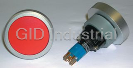
Description
EAO Switch 14-131.022 Pushbutton Switch - SPDT, 5A, 250V
Part Number
14-131.022
Price
Request Quote
Manufacturer
EAO SWITCH
Lead Time
Request Quote
Category
PRODUCTS - 1
Specifications
Actuator Diameter
22.5mm
Actuator Style
Roller Plunger
Circuitry
SPST
Contact Current
Max:5A
Leaded Process Compatible
Yes
RoHs Compliant
Yes
Supply Voltage
250VAC
Switch Operation
(On)
Datasheet

Extracted Text
EAO – Your Expert Partner for Human Machine Interfaces EAO Product Information Series 14 Switches and Indicators 14 Contents 14 Description ...................................................................................................... 3 Product Assembly .......................................................................................... 4 Devices raised mounting ............................................................................... 6 Devices flush mounting ............................................................................... 13 Accessories................................................................................................... 17 Technical Data............................................................................................... 27 Typical Applications..................................................................................... 30 Application guidelines.................................................................................. 31 Marking .......................................................................................................... 32 Drawings........................................................................................................ 36 Index............................................................................................................... 56 2 07.2009 Description 14 Specimen order 0 Product Information Illuminated pushbutton : - Illuminiated pushbutton actuator, 29 mm dia., 14-131.0252 General notes snap-action switching element, 1NC + 1 NO, The Series 14 illuminated pushbuttons combine the robust actuators of momentary action, soldering terminal the Series 04 with choice of either snap-action switching elements with Essential accessories : gold plated silver contacts for one changeover only. These pushbuttons have an IP 67 proof front (temporary emerson) and - Lens plastic red 704.602.2 can be immersed to a depth of one metre. - Marking plate white translucent 704.609.9 The range includes pushbuttons, keylock switches and selector - Front ring aluminium natural 704.600.1 switches. Anodized aluminium parts can have visible variations due production- - Single-LED, T5.5, 12 VAC/DC, white 10-2109.1069 technical reasons. Mounting We reserve the right to modify technical data Mounted from the front through either 22.5 mm dia cut out for raised or All dimensions in mm 30.5 mm dia for flush. The pushbuttons are secured to the panel by means of a fixing ring/ nut and prevented from twisting by two srews. To ensure correct positioning of the pushbuttons we can provide a positioning insert if required. The Low Level switching elements with universal terminals allow them to PCB mounted. These terminals are also suitable for dip soldering. A plug-in base is available, which when soldered to the board allows the switch to be easily plugged-in. Lenses Lenses of transparent plastic or aluminium are available in various standard colours. Marking For further information about engraving, hot stamping and film inserts see part Marking. Illumination The T5.5 incandescent (filament) lamp (6, 12, 24, 28, 30, 36, 48 V) ensures perfect illumination of the lenses, which are supplied in various colours. T5.5 Single-Chip LED (6, 12, 24, 28, 48 V) are also available in blue, green, red, white or yellow. Do not solder the terminals directly, because of the high surface temperature. Luminosity and wave length scattering caused by the technology used in the LED manufacturing processes may lead to visual differences in our products. Position indication The status of a maintained action switch can be determinded by the position of the lens. Keylock switch Single locks (2 positions). There are 10 different locks with standard numbers 1001 ... 1010. If the lock number is not specified, we will supply standard number 1001. Additional lock numbers are available on request. Two keys are supplied with each keylock switch. Spare keys for standard locks may be ordered by quoting Typ-Nr. 14-987 (please state the lock number). 3 07.2009 Product Assembly 14 Illuminated pushbutton, raised mounting 0 1 Front ring 2 Lens 1 3 Marking plate 4LED 2 5 Actuator housing with switching element 6 Front plate 3 7 Fixing nut 4 5 6 7 Illuminated pushbutton, flush mounting 0 1 Front bezel set, flush mounting 2 Lens 1 3 Marking plate 4LED 5 Actuator housing with switching element 2 6 Front panel 7 Pressure ring 3 8 Fixing nut 4 5 6 7 8 4 07.2009 Product Assembly 14 Keylock switch, raised mounting 0 1 Front ring 2 Actuator housing with switching element 1 3 Front plate 4 Fixing nut 2 3 4 Selector switch, flush mounting 0 1 Front ring 2 Actuator housing with switching element 1 3 Front plate 4 Anti-twist ring 5 Pressure ring 6 Fixing nut 2 3 4 5 6 5 07.2009 Devices raised mounting 14 Indicator actuator full face illumination Essential Accessories: d Lens cap page 18 d Marking cap for Lens cap page 19 d Single-LED page 24 Continuation see next page Ø 29 mm e Typ-Nr. Indicator actuator full face illumination IP 67 1 D UT 14-741.006 2517 56 0.011 2 D UT 14-742.006 2517 57 0.011 -S 14-030.005 5 17 3 0.010 S1 14-030.002 5 17 3 0.010 UT 14-031.006 2 5 17 2 0.011 Diode (1N 4007): D = Diode, - = without Terminals: UT = Universal terminal, S = Soldering terminal, S1 = Soldering terminal (also pluggable 2.8 x 0.5 mm) Component layout from page 36, Mounting dimensions from page 37, Technical drawing from page 38, Circuit drawing from page 48 Indicator actuator front illumination Essential Accessories: d Front ring page 19 d Lens plastic page 17 d Marking plate for Lens plastic and metal page 18 d Single-LED page 24 Continuation see next page Ø 29 mm e Typ-Nr. Indicator actuator front illumination IP 67 S 14-040.005 5 19 3 0.050 S1 14-040.002 5 19 3 0.050 UT 14-041.006 2 5 19 2 0.050 Terminals: S = Soldering terminal, S1 = Soldering terminal (also pluggable 2.8 x 0.5 mm), UT = Universal terminal Component layout from page 36, Mounting dimensions from page 37, Technical drawing from page 38, Circuit drawing from page 48 6 07.2009 Front protection Diode (1N 4007) Front protection Terminals Terminals Component layout Component layout Mounting dimensions Mounting dimensions Technical drawing Technical drawing Circuit drawing Circuit drawing Devices raised mounting 14 Buzzer Continuation see next page Ø 29 mm e Front cap Typ-Nr. Buzzer IP 65 Brass nickel-plated S1 14-810.902 5 110.016 Operation voltage 24 VDC Plastic black S1 14-810.002 5 110.016 Further information in the Technical Data and Typical Applications Terminals: S1 = Soldering terminal (also pluggable 2.8 x 0.5 mm) Mounting dimensions from page 37, Technical drawing from page 38, Circuit drawing from page 48 7 07.2009 Front protection Terminals Mounting dimensions Technical drawing Circuit drawing Devices raised mounting 14 Illuminated actuator pushbutton Essential Accessories: d Front ring page 19 d Lens plastic page 17 d Marking plate for Lens plastic and metal page 18 d Single-LED page 24 Continuation see next page Ø 29 mm e Contacts Typ-Nr. Illuminated actuator pushbutton IP 67 LL 1 NC - MA UT 14-476.036 2520 12 0.015 MUT 14-436.036 2520 39 0.015 1 NC + 1 NO - MA UT 14-473.036 2520 15 0.015 MUT 14-433.036 2520 42 0.015 1 NO - MA UT 14-475.036 2520 14 0.015 MUT 14-435.036 2520 41 0.015 2 NC - MA UT 14-472.036 2520 13 0.015 MUT 14-432.036 2520 40 0.015 2 NO - MA UT 14-471.036 2520 16 0.015 MUT 14-431.036 2520 43 0.015 SA 1 NC + 1 NO 1 D MA UT 14-747.0292 2 5 20 9 0.014 MUT 14-743.0292 2520 36 0.014 2 D MA UT 14-748.0292 2520 10 0.014 MUT 14-744.0292 2520 37 0.014 -MAS 14-271.0252 5 20 11 0.013 S1 14-271.022 5 20 11 0.013 MS 14-131.0252 5 20 38 0.013 S1 14-131.022 5 20 38 0.013 2 NC + 2 NO 1 D MA UT 14-749.0292 2 5 20 6 0.016 MUT 14-745.0292 2520 33 0.016 2 D MA UT 14-750.0292 2 5 20 7 0.016 MUT 14-746.0292 2520 34 0.016 -MAS 14-272.0252 5 20 8 0.015 MS 14-132.0252 5 20 35 0.015 3 NC + 3 NO - MA S 14-273.0252 5 20 5 0.017 MS 14-133.0252 5 20 32 0.017 4 NC + 4 NO - MA S 14-274.0252 5 20 4 0.019 MS 14-134.0252 5 20 31 0.019 Switching system: LL = Low level switching element, SA = Snap-action switching element Contacts: NC = Normally closed, NO = Normally open Diode (1N 4007): - = without, D = Diode Switching action: MA = Maintained action, M = Momentary action Terminals: UT = Universal terminal, S = Soldering terminal, S1 = Soldering terminal (also pluggable 2.8 x 0.5 mm) Component layout from page 36, Mounting dimensions from page 37, Technical drawing from page 38, Circuit drawing from page 48 8 07.2009 Front protection Switching system Diode (1N 4007) Switching action Terminals Component layout Mounting dimensions Technical drawing Circuit drawing Devices raised mounting 14 Mushroom-head actuator pushbutton Essential Accessories: d Front ring page 19 d Marking plate for Mushroom-head cap page 18 d Mushroom-head cap page 18 Continuation see next page Ø 40 mm e Contacts Typ-Nr. Mushroom-head actuator pushbutton IP 67 LL 1 NC MA UT 14-476.036 2 2 18 12 0.015 MUT 14-436.036 2 2 18 39 0.015 1 NC + 1 NO MA UT 14-473.036 2 2 18 15 0.015 MUT 14-433.036 2 2 18 42 0.015 1 NO MA UT 14-475.036 2 2 18 14 0.015 MUT 14-435.036 2 2 18 41 0.015 2 NC MA UT 14-472.036 2 2 18 13 0.015 MUT 14-432.036 2 2 18 40 0.015 2 NO MA UT 14-471.036 2 2 18 16 0.015 MUT 14-431.036 2 2 18 43 0.015 SA 1 NC + 1 NO MA S 14-271.0252 218 11 0.013 S1 14-271.022 218 11 0.013 MS 14-131.0252 218 38 0.013 S1 14-131.022 218 38 0.013 2 NC + 2 NO MA S 14-272.0252 2 18 8 0.015 MS 14-132.0252 218 35 0.015 3 NC + 3 NO MA S 14-273.0252 2 18 5 0.017 MS 14-133.0252 218 32 0.017 4 NC + 4 NO MA S 14-274.0252 2 18 4 0.019 MS 14-134.0252 218 31 0.019 Switching system: LL = Low level switching element, SA = Snap-action switching element Contacts: NC = Normally closed, NO = Normally open Switching action: MA = Maintained action, M = Momentary action Terminals: UT = Universal terminal, S = Soldering terminal, S1 = Soldering terminal (also pluggable 2.8 x 0.5 mm) Component layout from page 36, Mounting dimensions from page 37, Technical drawing from page 38, Circuit drawing from page 48 9 07.2009 Front protection Switching system Switching action Terminals Component layout Mounting dimensions Technical drawing Circuit drawing Devices raised mounting 14 Illuminated mushroom-head actuator pushbutton Essential Accessories: d Front ring page 19 d Marking plate for Mushroom-head cap page 18 d Mushroom-head cap illuminated page 18 d Single-LED page 24 Continuation see next page Ø 40 mm e Contacts Typ-Nr. Illuminated mushroom-head actuator pushbutton IP 67 LL 1 NC - MA UT 14-476.036 2218 12 0.015 MUT 14-436.036 2218 39 0.015 1 NC + 1 NO - MA UT 14-473.036 2218 15 0.015 MUT 14-433.036 2218 42 0.015 1 NO - MA UT 14-475.036 2218 14 0.015 MUT 14-435.036 2218 41 0.015 2 NC - MA UT 14-472.036 2218 13 0.015 MUT 14-432.036 2218 40 0.015 2 NO - MA UT 14-471.036 2218 16 0.015 MUT 14-431.036 2218 43 0.015 SA 1 NC + 1 NO 1 D MA UT 14-747.0292 2 2 18 9 0.014 MUT 14-743.0292 2218 36 0.014 2 D MA UT 14-748.0292 2218 10 0.014 MUT 14-744.0292 2218 37 0.014 -MAS 14-271.0252 2 18 11 0.013 S1 14-271.022 2 18 11 0.013 MS 14-131.0252 2 18 38 0.013 S1 14-131.022 2 18 38 0.013 2 NC + 2 NO 1 D MA UT 14-749.0292 2 2 18 6 0.016 MUT 14-745.0292 2218 33 0.016 2 D MA UT 14-750.0292 2 2 18 7 0.016 MUT 14-746.0292 2218 34 0.016 -MAS 14-272.0252 2 18 8 0.015 MS 14-132.0252 2 18 35 0.015 3 NC + 3 NO - MA S 14-273.0252 2 18 5 0.017 MS 14-133.0252 2 18 32 0.017 4 NC + 4 NO - MA S 14-274.0252 2 18 4 0.019 MS 14-134.0252 2 18 31 0.019 Switching system: LL = Low level switching element, SA = Snap-action switching element Contacts: NC = Normally closed, NO = Normally open Diode (1N 4007): - = without, D = Diode Switching action: MA = Maintained action, M = Momentary action Terminals: UT = Universal terminal, S = Soldering terminal, S1 = Soldering terminal (also pluggable 2.8 x 0.5 mm) Component layout from page 36, Mounting dimensions from page 37, Technical drawing from page 38, Circuit drawing from page 48 10 07.2009 Front protection Switching system Diode (1N 4007) Switching action Terminals Component layout Mounting dimensions Technical drawing Circuit drawing Devices raised mounting 14 Keylock switch 2 positions Continuation see next page Ø 29 mm Front ring Contacts Typ-Nr. e 0 Keylock switch 2 positions IP 65 Aluminium natural LL 1 NC + 1 NO MA UT A 14-415.036K 2 5 21 54 0.030 Position A : Basic position C 14-418.036K 2 5 21 54 0.030 Position C : Maintained action C + A 14-412.036K 2 5 21 54 0.030 Standard lock 1001, 2 NO MA UT A 14-414.036K 2 5 21 55 0.030 Front : Plastic black C 14-417.036K 2 5 21 55 0.030 C + A 14-411.036K 2 5 21 55 0.030 SA 1 NC + 1 NO MA S A 14-235.025K2 521 50 0.029 C 14-335.025K2 521 50 0.029 C + A 14-135.025K2 521 50 0.029 S1 A 14-235.022K 521 50 0.029 C 14-335.022K 521 50 0.029 C + A 14-135.022K 521 50 0.029 2 NC + 2 NO MA S A 14-236.025K2 521 51 0.031 C 14-336.025K2 521 51 0.031 C + A 14-136.025K2 521 51 0.031 3 NC + 3 NO MA S A 14-237.025K2 521 52 0.033 C 14-337.025K2 521 52 0.033 C + A 14-137.025K2 521 52 0.033 4 NC + 4 NO MA S A 14-238.025K2 521 53 0.035 C 14-338.025K2 521 53 0.035 C + A 14-138.025K2 521 53 0.035 Position A : Basic position IP 65 Aluminium natural LL 1 NC + 1 NO M UT A 14-438.036K 2 5 21 48 0.030 Position C : Momentary action 2 NO M UT A 14-437.036K 2 5 21 49 0.030 Standard lock 1001 SA 1 NC + 1 NO M S A 14-141.025K2 521 44 0.029 Front : Plastic black S1 A 14-141.022K 521 44 0.029 2 NC + 2 NO M S A 14-142.025K2 521 45 0.031 3 NC + 3 NO M S A 14-143.025K2 521 46 0.033 4 NC + 4 NO M S A 14-144.025K2 521 47 0.035 Keylock switches are supplied with 2 keys. Other lock numbers on request Switching system: LL = Low level switching element, SA = Snap-action switching element Contacts: NC = Normally closed, NO = Normally open Switching action: MA = Maintained action, M = Momentary action Terminals: UT = Universal terminal, S = Soldering terminal, S1 = Soldering terminal (also pluggable 2.8 x 0.5 mm) Component layout from page 36, Mounting dimensions from page 37, Technical drawing from page 38, Circuit drawing from page 48 11 07.2009 Front protection Switching system Switching action Terminals Key remove Component layout Mounting dimensions Technical drawing Circuit drawing Devices raised mounting 14 Selector switch 2 positions non-illuminative Continuation see next page Ø 29 mm Front ring Lever Contacts Typ-Nr. e 0 Selector switch IP 67 Aluminium Plastic black long LL 1 NC + 1 NO MA UT 14-572.0360 2 5 22 29 0.025 2 positions natural MUT 14-567.0360 2 5 22 22 0.025 Position A : Basic position 2 NC MA UT 14-571.0360 2 5 22 28 0.025 MUT 14-566.0360 2 5 22 21 0.025 2 NO MA UT 14-570.0360 2 5 22 30 0.025 MUT 14-565.0360 2 5 22 23 0.025 SA 1 NC + 1 NO MA S 14-556.02502 522 24 0.024 S1 14-556.0220 522 24 0.024 MS 14-551.02502 522 17 0.024 S1 14-551.0220 522 17 0.024 2 NC + 2 NO MA S 14-557.02502 522 25 0.026 MS 14-552.02502 522 18 0.026 3 NC + 3 NO MA S 14-558.02502 522 26 0.028 MS 14-553.02502 522 19 0.028 4 NC + 4 NO MA S 14-559.02502 522 27 0.030 MS 14-554.02502 522 20 0.030 Plastic black short LL 1 NC + 1 NO MA UT 14-522.0360 2 5 23 29 0.025 MUT 14-517.0360 2 5 23 22 0.025 2 NC MA UT 14-521.0360 2 5 23 28 0.025 MUT 14-516.0360 2 5 23 21 0.025 2 NO MA UT 14-520.0360 2 5 23 30 0.025 MUT 14-515.0360 2 5 23 23 0.025 SA 1 NC + 1 NO MA S 14-506.02502 523 24 0.024 S1 14-506.0220 523 24 0.024 MS 14-501.02502 523 17 0.024 S1 14-501.0220 523 17 0.024 2 NC + 2 NO MA S 14-507.02502 523 25 0.026 MS 14-502.02502 523 18 0.026 3 NC + 3 NO MA S 14-508.02502 523 26 0.028 MS 14-503.02502 523 19 0.028 4 NC + 4 NO MA S 14-509.02502 523 27 0.030 MS 14-504.02502 523 20 0.030 Switching system: LL = Low level switching element, SA = Snap-action switching element Contacts: NC = Normally closed, NO = Normally open Switching action: MA = Maintained action, M = Momentary action Terminals: UT = Universal terminal, S = Soldering terminal, S1 = Soldering terminal (also pluggable 2.8 x 0.5 mm) Component layout from page 36, Mounting dimensions from page 37, Technical drawing from page 38, Circuit drawing from page 48 12 07.2009 Front protection Switching system Switching action Terminals Component layout Mounting dimensions Technical drawing Circuit drawing Devices flush mounting 14 Indicator actuator, flush mounting Essential Accessories: d Front bezel set, flush mounting page 20 d Lens plastic page 17 d Marking plate for Lens plastic and metal page 18 d Single-LED page 24 Continuation see next page Ø 35 mm e Typ-Nr. Indicator actuator, flush mounting IP 67 S 14-040.005 1 24 3 0.050 S1 14-040.002 1 24 3 0.050 UT 14-041.006 2 1 24 2 0.050 Terminals: S = Soldering terminal, S1 = Soldering terminal (also pluggable 2.8 x 0.5 mm), UT = Universal terminal Component layout from page 36, Mounting dimensions from page 37, Technical drawing from page 38, Circuit drawing from page 48 Buzzer, flush mounting Continuation see next page Ø 35 mm e Front cap Typ-Nr. Buzzer, flush mounting IP 40 Aluminium black S1 14-810.910 1 16 1 0.016 Operation voltage : 24 VDC Aluminium natural S1 14-810.918 1 16 1 0.016 Further information in the Technical Data and Typical Applications Terminals: S1 = Soldering terminal (also pluggable 2.8 x 0.5 mm) Mounting dimensions from page 37, Technical drawing from page 38, Circuit drawing from page 48 13 07.2009 Front protection Front protection Terminals Terminals Component layout Mounting dimensions Mounting dimensions Technical drawing Technical drawing Circuit drawing Circuit drawing Devices flush mounting 14 Illuminated pushbutton actuator, flush mounting Essential Accessories: d Front bezel set, flush mounting page 20 d Lens plastic page 17 d Marking plate for Lens plastic and metal page 18 d Single-LED page 24 Continuation see next page Ø 35 mm e Contacts Typ-Nr. Illuminated pushbutton actuator, flush mounting IP 67 LL 1 NC - MA UT 14-476.036 2125 12 0.015 MUT 14-436.036 2125 39 0.015 1 NC + 1 NO - MA UT 14-473.036 2125 15 0.015 MUT 14-433.036 2125 42 0.015 1 NO - MA UT 14-475.036 2125 14 0.015 MUT 14-435.036 2125 41 0.015 2 NC - MA UT 14-472.036 2125 13 0.015 MUT 14-432.036 2125 40 0.015 2 NO - MA UT 14-471.036 2125 16 0.015 MUT 14-431.036 2125 43 0.015 SA 1 NC + 1 NO 1 D MA UT 14-747.0292 2 1 25 9 0.014 MUT 14-743.0292 2125 36 0.014 2 D MA UT 14-748.0292 2125 10 0.014 MUT 14-744.0292 2125 37 0.014 -MAS 14-271.0252 1 25 11 0.013 S1 14-271.022 1 25 11 0.013 MS 14-131.0252 1 25 38 0.013 S1 14-131.022 1 25 38 0.013 2 NC + 2 NO 1 D MA UT 14-749.0292 2 1 25 6 0.016 MUT 14-745.0292 2125 33 0.016 2 D MA UT 14-750.0292 2 1 25 7 0.016 MUT 14-746.0292 2125 34 0.016 -MAS 14-272.0252 1 25 8 0.015 MS 14-132.0252 1 25 35 0.015 3 NC + 3 NO - MA S 14-273.0252 1 25 5 0.017 MS 14-133.0252 1 25 32 0.017 4 NC + 4 NO - MA S 14-274.0252 1 25 4 0.019 MS 14-134.0252 1 25 31 0.019 Switching system: LL = Low level switching element, SA = Snap-action switching element Contacts: NC = Normally closed, NO = Normally open Diode (1N 4007): - = without, D = Diode Switching action: MA = Maintained action, M = Momentary action Terminals: UT = Universal terminal, S = Soldering terminal, S1 = Soldering terminal (also pluggable 2.8 x 0.5 mm) Component layout from page 36, Mounting dimensions from page 37, Technical drawing from page 38, Circuit drawing from page 48 14 07.2009 Front protection Switching system Diode (1N 4007) Switching action Terminals Component layout Mounting dimensions Technical drawing Circuit drawing Devices flush mounting 14 Keylock switch actuator 2 positions, flush mounting Essential Accessories: d Anti-twist ring, flush mounting page 25 d Front bezel set, flush mounting page 20 Continuation see next page Ø 35 mm e Contacts Typ-Nr. 0 Keylock switch actuator 2 positions, flush IP 65 LL 1 NC + 1 NO MA UT A 14-415.036K 2 1 26 54 0.030 mounting C 14-418.036K 2 1 26 54 0.030 Position A : Basic position C + A 14-412.036K 2 1 26 54 0.030 Position C : Maintained action 2 NO MA UT A 14-414.036K 2 1 26 55 0.030 Standard lock 1001, C 14-417.036K 2 1 26 55 0.030 Front : Plastic black C + A 14-411.036K 2 1 26 55 0.030 SA 1 NC + 1 NO MA S A 14-235.025K2 126 50 0.029 C 14-335.025K2 126 50 0.029 C + A 14-135.025K2 126 50 0.029 S1 A 14-235.022K 126 50 0.029 C 14-335.022K 126 50 0.029 C + A 14-135.022K 126 50 0.029 2 NC + 2 NO MA S A 14-236.025K2 126 51 0.031 C 14-336.025K2 126 51 0.031 C + A 14-136.025K2 126 51 0.031 3 NC + 3 NO MA S A 14-237.025K2 126 52 0.033 C 14-337.025K2 126 52 0.033 C + A 14-137.025K2 126 52 0.033 4 NC + 4 NO MA S A 14-238.025K2 126 53 0.035 C 14-338.025K2 126 53 0.035 C + A 14-138.025K2 126 53 0.035 Position A : Basic position IP 65 LL 1 NC + 1 NO M UT A 14-438.036K 2 1 26 48 0.030 Position C : Momentary action 2 NO M UT A 14-437.036K 2 1 26 49 0.030 Standard lock 1001 SA 1 NC + 1 NO M S A 14-141.025K2 126 44 0.029 Front : Plastic black S1 A 14-141.022K 126 44 0.029 2 NC + 2 NO M S A 14-142.025K2 126 45 0.031 3 NC + 3 NO M S A 14-143.025K2 126 46 0.033 4 NC + 4 NO M S A 14-144.025K2 126 47 0.035 Keylock switches are supplied with 2 keys. Other lock numbers on request Switching system: LL = Low level switching element, SA = Snap-action switching element Contacts: NC = Normally closed, NO = Normally open Switching action: MA = Maintained action, M = Momentary action Terminals: UT = Universal terminal, S = Soldering terminal, S1 = Soldering terminal (also pluggable 2.8 x 0.5 mm) Component layout from page 36, Mounting dimensions from page 37, Technical drawing from page 38, Circuit drawing from page 48 15 07.2009 Front protection Switching system Switching action Terminals Key remove Component layout Mounting dimensions Technical drawing Circuit drawing Devices flush mounting 14 Selector switch actuator 2 positions, flush mounting Essential Accessories: d Anti-twist ring, flush mounting page 25 d Front bezel set, flush mounting page 20 Continuation see next page Ø 35 mm e Lever Contacts Typ-Nr. 0 Selector switch actuator 2 positions, IP 67 Plastic black short LL 1 NC + 1 NO MA UT 14-522.0360 2127 29 0.025 flush mounting MUT 14-517.0360 2127 22 0.025 Position A : Basic position 2 NC MA UT 14-521.0360 2127 28 0.025 MUT 14-516.0360 2127 21 0.025 2 NO MA UT 14-520.0360 2127 30 0.025 MUT 14-515.0360 2127 23 0.025 SA 1 NC + 1 NO MA S 14-506.02502 1 27 24 0.024 S1 14-506.0220 1 27 24 0.024 MS 14-501.02502 1 27 17 0.024 S1 14-501.0220 1 27 17 0.024 2 NC + 2 NO MA S 14-507.02502 1 27 25 0.026 MS 14-502.02502 1 27 18 0.026 3 NC + 3 NO MA S 14-508.02502 1 27 26 0.028 MS 14-503.02502 1 27 19 0.028 4 NC + 4 NO MA S 14-509.02502 1 27 27 0.030 MS 14-504.02502 1 27 20 0.030 Switching system: LL = Low level switching element, SA = Snap-action switching element Contacts: NC = Normally closed, NO = Normally open Switching action: MA = Maintained action, M = Momentary action Terminals: UT = Universal terminal, S = Soldering terminal, S1 = Soldering terminal (also pluggable 2.8 x 0.5 mm) Component layout from page 36, Mounting dimensions from page 37, Technical drawing from page 38, Circuit drawing from page 48 16 07.2009 Front protection Switching system Switching action Terminals Component layout Mounting dimensions Technical drawing Circuit drawing Accessories 14 Front Lens plastic To obtain IP 67 use Marking plate Typ-Nr. 704.609.X Continuation see next page Ø 29 mm e Lens Typ-Nr. Lens plastic black opaque flush 704.602.0 0.001 blue transparent flush 704.602.6 0.001 colourless transparent flush 704.602.7 0.001 green transparent flush 704.602.5 0.001 red transparent flush 704.602.2 0.001 yellow transparent flush 704.602.4 0.001 Lens raised, plastic To obtain IP 67 use Marking plate Typ-Nr. 704.610.X Continuation see next page Ø 29 mm e Lens Typ-Nr. Lens raised, plastic colourless transparent flush 704.611.7 0.002 green transparent flush 704.611.5 0.002 red transparent flush 704.611.2 0.002 yellow transparent flush 704.611.4 0.002 Lens metal with spot To obtain IP 67 use Marking plate Typ-Nr. 704.609.X Continuation see next page Ø 29 mm e Lens Typ-Nr. Lens metal with spot Aluminium black flush 704.601.01 0.001 Aluminium blue flush 704.601.61 0.001 Aluminium gold flush 704.601.41 0.001 Aluminium natural flush 704.601.81 0.001 Aluminium olive-green flush 704.601.51 0.001 Aluminium red flush 704.601.21 0.001 Stainless steel natural flush 704.601.91 0.001 Lens metal To obtain IP 67 use Marking plate Typ-Nr. 704.609.9 Continuation see next page Ø 29 mm e Lens Typ-Nr. Lens metal Aluminium black flush 704.601.0 0.001 Aluminium blue flush 704.601.6 0.001 Aluminium gold flush 704.601.4 0.001 Aluminium natural flush 704.601.8 0.001 Aluminium olive-green flush 704.601.5 0.001 Aluminium red flush 704.601.2 0.001 Stainless steel natural flush 704.601.9 0.001 17 07.2009 Accessories 14 Lens cap To obtain IP 67 use Marking plate Typ-Nr. 704.608.X Continuation see next page Ø 29 mm e Lens Typ-Nr. Lens cap Plastic blue transparent 704.603.6 0.003 Plastic colourless transparent 704.603.7 0.003 Plastic green transparent 704.603.5 0.003 Plastic red transparent 704.603.2 0.003 Plastic yellow transparent 704.603.4 0.003 Mushroom-head cap To obtain IP 67 use Marking plate Typ-Nr. 704.609.9 Continuation see next page Ø 40 mm e Mushroom had cap Typ-Nr. Mushroom-head cap Plastic black opaque 704.604.0 0.001 Plastic green opaque 704.604.5 0.001 Plastic red opaque 704.604.2 0.001 Plastic yellow opaque 704.604.4 0.001 Mushroom-head cap illuminated To obtain IP 67 use Marking plate Typ-Nr. 704.609.9 Continuation see next page Ø 40 mm e Mushroom had cap Typ-Nr. Mushroom-head cap illuminated Plastic blue transparent 704.614.6 0.007 Plastic colourless transparent 704.614.7 0.007 Plastic green transparent 704.614.5 0.007 Plastic red transparent 704.614.2 0.007 Plastic yellow transparent 704.614.4 0.007 Marking plate for Lens plastic and metal Continuation see next page e Marking plate Typ-Nr. Marking plate for Lens plastic and metal Plastic colourless transparent ribbed 704.609.7 0.001 LED LED and Filament lamp Plastic white translucent 704.609.9 0.001 non-illuminative Plastic black opaque 704.609.0 0.001 Marking plate for Mushroom-head cap Continuation see next page e Marking plate Typ-Nr. Marking plate for Mushroom-head cap Plastic white translucent 704.609.9 0.001 18 07.2009 Accessories 14 Marking cap for Lens raised, plastic Continuation see next page e Marking cap Typ-Nr. Marking cap for Lens raised, plastic Plastic colourless transparent ribbed 704.610.7 0.001 LED LED and Filament lamp Plastic white translucent 704.610.9 0.001 Marking cap for Lens cap Continuation see next page e Marking cap Typ-Nr. Marking cap for Lens cap Plastic colourless transparent ribbed 704.608.7 0.002 LED LED and Filament lamp Plastic white translucent 704.608.9 0.002 Front ring Continuation see next page Ø 29 mm e Typ-Nr. Front ring 704.600.0 0.003 704.600.6 0.003 704.600.1 0.005 704.600.1A 0.005 704.600.9 0.006 Front bezel set for Mushroom-head pushbutton Continuation see next page Ø 50 mm e Front Bezel Typ-Nr. Front bezel set for Mushroom-head pushbutton Aluminium black 14-958.0 4 28 0.042 Aluminium natural 14-958.8 4 28 0.042 Mounting dimensions from page 37, Technical drawing from page 38 19 07.2009 Mounting dimensions Technical drawing Accessories 14 Front bezel set, flush mounting Continuation see next page Ø 35 mm e Front bezel Typ-Nr. Front bezel set, flush mounting Aluminium black 704.955.0 1 0.015 Aluminium natural 704.955.1 1 0.015 Stainless steel natural 704.955.9 1 0.033 Mounting dimensions from page 37 Legend frame adhesive, Aluminium black Continuation see next page e Typ-Nr. Legend frame 704.968.2 9 0.001 30 x 50 mm for raised mounting 35 x 57.5 mm for flush mounting 704.968.3 10 0.001 Technical drawing from page 38 Legend plate insert for Legend frame 704.968.2 and 704.968.3 Continuation see next page e Typ-Nr. Legend plate insert 704.968.1 0.001 14.5 x 23.5 mm, adhesive, Aluminium black 14.5 x 23.5 mm, adhesive, Aluminium natural 704.968.0 0.001 Protective cover, raised mounting Mounting hole size 22.5 mm dia. Continuation see next page e Typ-Nr. Protective cover, raised mounting 704.925.0 4 0.007 hinged, transparent, with means for sealing, for Pushbutton hinged, transparent, with means for sealing, for Selector switch 704.925.2 6 0.007 hinged, transparent, with means for sealing, with spring fitted, for Pushbutton 704.925.3 4 0.007 Protection cover 704.925.2 only for selector switches in basic position A applicable. Technical drawing from page 38 20 07.2009 Technical drawing Technical drawing Mounting dimensions Accessories 14 Protective cover, flush mounting Mounting hole size 30.5 mm dia. Continuation see next page e Typ-Nr. Protective cover, flush mounting 704.928.38 8 0.019 hinged, Aluminium natural, with means for sealing, for Pushbutton and Selector switch short lever hinged, Aluminium natural, with means for sealing, spring fitted, for Pushbutton and Selector 704.928.28 5 0.019 switch short lever hinged, Aluminium natural, with window, spring fitted, for Pushbutton 704.928.18 7 0.019 Technical drawing from page 38 Front protective cap for Indicator and Illuminated pushbutton for protection IP 68 Continuation see next page e Front protective cap Typ-Nr. Front protective cap Silicone colourless transparent 704.953.0 0.002 only together with Lenses 704.602.X, 704.601.X and Front rings 704.600.X Front protective ring for Illuminated pushbutton with front illumination (IP 67) Continuation see next page Ø 29 mm e Front protective ring Typ-Nr. Front protective ring Aluminium natural 704.600.5/A 0.005 with transparent Pebax membrane, temperature resistance -40 °C ... +85 °C with transparent silicone membrane (extent resistant to sea water), Aluminium natural 704.600.3 0.005 temperature resistance -40 °C ... +85 °C Chromed brass 704.600.2 0.005 Front protective ring to be mounted with a torque of 40 Ncm onto actuator. Front bezel with protective membrane, flush mounting for Illuminated pushbutton (IP 67) Continuation see next page Ø 35 mm e Front bezel Typ-Nr. Front bezel with protective membrane, flush mounting Aluminium black 704.955.4 0.015 with transparent silicone membrane Aluminium natural 704.955.3 0.015 with transparent silicone membrane, resistant to sea water Stainless steel natural 704.955.9E 0.033 Front bezel to be mounted with a torque of 40 Ncm onto actuator. 21 07.2009 Technical drawing Accessories 14 Blind plug Continuation see next page e Blind plug Typ-Nr. Blind plug Plastic black IP 65 704.960.4 3 0.004 Size 28 mm dia., for mounting hole 22.5 mm dia. Size 36 mm dia., for mounting hole 30.5 mm dia. Plastic black IP 65 704.964.8 2 0.007 Technical drawing from page 38 Spare key Continuation see next page e Typ-Nr. Spare key 14-987.1001 0.006 Standard lock 1001 (KABA) Other lock numbers on request > Backside PCB plug-in base Continuation see next page Typ-Nr. e PCB plug-in base 31-940 3 0.002 16.4 mm dia. x 9.8 mm for Low level switching element, Pins axial 17.8 x 12.9 mm x 9.8 mm for Snap-action switching element 2.8 mm, Pins axial 31-942 4 0.002 17.9 x 17.9 x 8.4 mm for Low level switching element, Pins bent at right-angle 31-941 1 0.004 PCB plug-in base Pins right-angle : With the extendable mounting the distance between plug-in base and PCB can be varied up to 3 mm. Component layout from page 36 Flat receptacle Continuation see next page e Typ-Nr. Flat receptacle 31-945 0.001 2.0 x 0.5 mm for Universal terminal 2.8 x 0.5 mm for Plug-in terminal 31-946 0.001 22 07.2009 Front protection Component layout Technical drawing Accessories 14 Insulation sleeve Continuation see next page e Typ-Nr. Insulation sleeve 01-928 0.001 Cover Plug-in terminals for snap-action switching element 2.8 mm for Flat receptacle 31-945 31-928 0.001 for Flat receptacle 31-946 31-929 0.001 Terminal cover Continuation see next page e Typ-Nr. Terminal cover 01-929 0.010 > Illumination Filament lamp Continuation see next page e Socket Operating voltage/-current Typ-Nr. Filament lamp T5.5 12 VAC/DC, 100 mA 10-1109.1329 0.001 12 VAC/DC, 50 mA 10-1109.1279 0.001 24 VAC/DC, 25 mA 10-1112.1199 0.001 24 VAC/DC, 50 mA 10-1112.1279 0.001 28 VAC/DC, 40 mA 10-1113.1249 0.001 30 VAC/DC, 40 mA 10-1114.1249 0.001 36 VAC/DC, 35 mA 10-1116.1229 0.001 48 VAC/DC, 25 mA 10-1119.1199 0.001 6 VAC/DC, 200 mA 10-1106.1369 0.001 23 07.2009 Accessories 14 Single-LED Continuation see next page e Socket Light colour Operating voltage/-current Typ-Nr. Single-LED T5.5 blue 12 VAC/DC, 7/14 mA 10-2109.1066 0.001 24 VAC/DC, 7/14 mA 10-2112.1066 0.001 28 VAC/DC, 7/14 mA 10-2113.1066 0.001 48 VAC/DC, 4/8 mA 10-2119.1046 0.001 6 VDC, 15 mA 10-2106.3146 0.001 green 12 VAC/DC, 7/14 mA 10-2109.1065 0.001 24 VAC/DC, 7/14 mA 10-2112.1065 0.001 28 VAC/DC, 7/14 mA 10-2113.1065 0.001 48 VAC/DC, 4/8 mA 10-2119.1045 0.001 6 VDC, 15 mA 10-2106.3145 0.001 red 12 VAC/DC, 7/14 mA 10-2109.1062 0.001 24 VAC/DC, 7/14 mA 10-2112.1062 0.001 28 VAC/DC, 7/14 mA 10-2113.1062 0.001 48 VAC/DC, 4/8 mA 10-2119.1042 0.001 6 VDC, 15 mA 10-2106.3142 0.001 white diffuse 12 VAC/DC, 7/14 mA 10-2109.1069 0.001 24 VAC/DC, 7/14 mA 10-2112.1069 0.001 28 VAC/DC, 7/14 mA 10-2113.1069 0.001 48 VAC/DC, 4/8 mA 10-2119.1049 0.001 6 VDC, 15 mA 10-2106.3149 0.001 yellow 12 VAC/DC, 7/14 mA 10-2109.1064 0.001 24 VAC/DC, 7/14 mA 10-2112.1064 0.001 28 VAC/DC, 7/14 mA 10-2113.1064 0.001 48 VAC/DC, 4/8 mA 10-2119.1044 0.001 6 VDC, 15 mA 10-2106.3144 0.001 Note: AC operation through halve-wave rectifier possible, slight flickering can occure. Terminal plate empty for fitting with series resistors Continuation see next page e Typ-Nr. Terminal plate empty 02-912.2 0.045 10 spaces 125 x 60 x 15 mm 15 spaces 187.5 x 60 x 15 mm 02-912.3 0.090 20 spaces 250 x 60 x 15 mm 02-912.4 0.095 5 spaces 62.5 x 60 x 15 mm 02-912.1 0.025 24 07.2009 Accessories 14 > Assembling Positioning insert Continuation see next page e Typ-Nr. Positioning insert 14-910 3 0.001 Mounting dimensions from page 37 Anti-twist ring, flush mounting Continuation see next page e Typ-Nr. Anti-twist ring, flush mounting 704.954.0 0.002 Reducing ring Devices 22.5 mm dia. in mounting hole size 30.5 mm dia. Continuation see next page e Typ-Nr. Reducing ring 704.960.0 0.004 Aluminium black Aluminium natural 704.960.8 0.004 You need to install two reduction rings. Lens plug for round lens, flush mounting Continuation see next page e Typ-Nr. Lens plug for round lens, flush mounting 700.006.0 0.003 for mounting and dismantling of Lens round, flush mounting Lamp remover Continuation see next page e Typ-Nr. Lamp remover 02-906 0.002 CAUTION A switching process might be released when replacing the Lamp/LED ! 25 07.2009 Mounting dimensions Accessories 14 Enclosure Grey similar RAL 7035; cover lead-sealable Continuation see next page e Dimension Typ-Nr. Enclosure L 94 mm, W 94 mm, H 81 mm 704.945.1 11 0.211 with mounting hole 1 x 22.5 mm dia., with anti-twist device with mounting hole 2 x 22.5 mm dia., with anti-twist device L 130 mm, W 94 mm, H 81 mm 704.945.2 12 0.251 with mounting hole 3 x 22.5 mm dia., with anti-twist device L 180 mm, W 94 mm, H 81 mm 704.945.3 13 0.313 with mounting hole 4 x 22.5 mm dia., with anti-twist device L 180 mm, W 182 mm, H 110 mm 704.945.4 14 0.572 with mounting hole 6 x 22.5 mm dia., with anti-twist device L 180 mm, W 182 mm, H 110 mm 704.945.5 15 0.568 Openings for cable gland M16 or M20. Protection class IP 66. Technical drawing from page 38 Cable gland Continuation see next page e Typ-Nr. Cable gland 61-9481.6 0.007 M16, Plastic grey M20, Plastic grey 704.945.6 0.011 with traction relief; protection degree IP 68. 26 07.2009 Technical drawing Technical Data 14 Electrical characteristics Actuator with snap-action switching element Standards The devices comply with : EN IEC 61058-1 Switching system Self-cleaning, double-break, snap action switching system (with Rated voltage contact gap 2 x 0.5 mm). 250 VAC/DC as per EN IEC 61058-1-15 1 normally closed or 1 normally open contact per element. Snap-action switching elements with soldering terminals at the Contact resistance sides: up to 4 switching element can be on a pushbutton (max. 4 New state ≤50 mΩ as per DIN IEC 60512-2-4 normally closed and 4 normally open contacts). Snap-action switching element with axial plug-in terminals 2.8 mm Electrostatic discharge (ESD) stackable, only 1 switching element can be on a pushbutton. Keylock switch 15 kV Rated current Material 5 A Material of contact Conventional free air thermal current I th Gold plated silver 5 A The maximum current in continuous operation and at ambient Switch housing temperature not exceeding the quoted maximum values. Plug-in-/soldering terminal Diallylphthalate DAP, Polyamide 66, Polysulfone, heat-resistant Switch rating and self-extinguishing 250 VAC, 5 A (cosφ 1) Soldering terminal: PA 6.6 Ultramide 250 VAC, 3 A (cosφ 0,3) Actuator housing Switch rating AC (cosφ 0,7) Polyamide 0 Voltage 125 VAC 250 VAC Current 3 A 2 A Mechanical characteristics Switch rating DC (inductive) L:R = 30 ms Terminals 0 Snap-action switching element with tinned soldering terminals at Voltage 24 VDC 60 VDC 110 VDC 220 VDC the sides: Current 2 A 0.7 A 0.2 A 0.1 A Max. wire diameter 2 wires à 1.2 mm max. wire cross-section of stranded cable 1x 1 mm² Electric strength 3000 VAC, 50 Hz, 1 min. between all terminals and earth, as per EN Snap-action switching element with axial plug-in terminals, which IEC 61058-1-15 can also be used as soldering terminals: Plug-in terminal 2.8 x 0.5 Isolation resistance mm >7 MΩ between the opend contats at 500 VDC, as per EN IEC 61058-1-15 (reinforced insulation) Soldering terminal: Max. wire diameter 2 wires of 1 mm Protection class Max. wire cross-section of stranded cable 2 x 0.75 mm² or 1 x 1.0 II mm² Actuating torque Environmental conditions Measured at the key or lever of the keylock- or selector switch 2.5 Ncm ... 5.5 Ncm, depending on the number of switching Storage temperature elements -40 °C ... +85 °C Actuating force Service temperature Maintain 5 N ... 7.8 N -25 °C ... +55 °C Momentary 3.2 N ... 6 N For indicators and illuminated pushbuttons mounted as a block, depending on the number of switching elements make sure the heat can escape freely. Actuating travel Protection degree 0 as per EN IEC 60529 Illuminated pushbutton: 3 mm front side IP 67 Switch actuator 2 positions: Momentary action 1 x ca. 42° deflection momentary action Shock resistance Maintained action 1 x ca. 90° deflection maintained action (semi-sinusoidal) max. 150 m/s², pulse width 11 ms, 3-axis, as per EN IEC 60068-2- Rebound time 27 ≤5ms Vibration resistance Mechanical lifetime 0 (sinusoidal) Momentary action 2 million Cycles of operation max. 100 m/s² at 10 Hz ... 500 Hz, as per EN IEC 60068-2-6 Maintained action 1 million Cycles of operation 27 07.2009 Technical Data 14 Climate resistance Rebound time Damp heat state as per EN IEC 60068-2-30 typical <100 μs Damp heat cyclic as per EN IEC 60068-2-78 Mechanical lifetime Momentary action 5 million cycles of operation Approvals Maintained action 1 million cycles of operation Approbations Electrical characteristics CB (IEC 61058) CSA Contact resistance ENEC (EN 61058) New state ≤50 mΩ as per DIN IEC 60512-2-4 Germanischer Lloyd UL Electrostatic discharge (ESD) Keylock switch 15 kV Declaration of conformity CE > Switch rating 10 μA, 100 μV to 100 mA at 42 VAC/VDC Actuator with low level switching element Electric strength Switching system 3000 VAC, 50 Hz, 1 min. between all terminals and earth, as per EN This low level switching element was designed for switching low IEC 61058-1-15 powers in electronic circuits. The mechanism assures reliable Protection class switching of loads ranging from a few μA/μV up to 100 mA/42 VAC/ II DC. Single-break momentary contact, as normally open or normally closed with 4 independent points of contact. 2 momentary contacts Environmental conditions per switching element; combination of normally open and normally closed is possible. Storage temperature Special features are the long life, extremely short rebound time and -40 °C ... +85 °C stable contact resistance. Service temperature -25 °C ... +55 °C Material For indicators and illuminated pushbuttons mounted as a block, make sure the heat can escape freely. Material of contact Gold plated Protection degree as per EN IEC 60529 Switch housing front side IP 67 Polysulfone, heat-resistant and self-extinguishing Shock resistance Actuator housing (semi-sinusoidal) Polyamide max. 150 m/s², pulse width 11 ms, 3-axis, as per EN IEC 60068-2- 27 Mechanical characteristics > Buzzer Terminals The universal terminals permit these units to be mounted on printed Buzzer system circuit boards (PCB). These terminals can also be used as soldering or plug-in terminals. System For these terminals we can also supply a plug-in base which, when Piezo disc soldered on to the board, enables the switch to be plugged in. Soldering terminal: Max. wire diameter 2 wires of 1 mm Material Max. wire cross-section of stranded cable 2 x 0.75 mm² Plug-in terminal: 2.0 x 0.5 mm. Alarm buzzer case Polyamide Actuating torque Measured at the key or lever of the keylock- or selector switch Front cap 2.5 Ncm ... 5.5 Ncm, depending on the number of switching Plastic Polyamide elements Metal Nickel-plated brass (sea-water proof) Actuating force Mechanical characteristics 3 ... 4 N, depending on the number of switching elements Terminals Actuating travel 0 Plug-in terminal 2.8 x 0.5 mm Illuminated pushbutton : 3 mm Switch actuator 2 positions: Electrical characteristics Momentary action 1 x ca. 42° deflection momentary action Maintained action 1 x ca. 90° deflection maintained action Frequency (tone) approx. 2.8 kHz continuous tone only 28 07.2009 Technical Data 14 Sound pressure 95 db (A) ±8 dB at a distance of 0.1 m Operation Voltage/Current 0 Operation Voltage 24 VDC ±10 % Operation Current ≤25 mA Environmental conditions Storage temperature -40 °C ... +85 °C Operating temperature -25 °C ... +55 °C Protection degree as per EN IEC 60529, frontside IP 40, devices flush mounting IP 65, devices raised mounting Approvals Declaration of conformity CE 29 07.2009 Typical Applications 14 Diode element When indicators and illuminated pushbuttons equipped with diodes, the user is able to perform a lamp check or wire an alarm circuit simply with a considerable saving of space. 0 30 07.2009 Application guidelines 14 Suppressor circuits When switching inductive loads such as relays, DC motors, and DC solenoids, it is always important to absorb surges (e.g. with a diode) to protect the contacts. When these inductive loads are switched off, a counter emf can severely damage switch contacts and greatly shorten lifetime. Fig. 1 shows an inductive load with a free-wheeling diode connected in parallel. This free-wheeling diode provides a path for the inductor current to flow when the current is interrupted by the switch. Without this free-wheeling diode, the voltage across the coil will be limited only by dielectric break- down voltages of the circuit or parasitic elements of the coil. This voltage can be kilovolts in amplitude even when nominal circuit voltages are low (e.g. 12 VDC) see Fig. 2. The free-wheeling diode should be chosen so that the reverse breakdown voltage is greater than the voltage driving the inductive load. The DC blocking voltage (VR) of the free-wheeling diode can be found in the datasheet of a diode. The forward current should be equal or greater than the maximum current flowing through the load. To get an efficient protection, the free-wheeling diode must be connected as close as possible to the inductive load! 0 Counter emf Switching with inductive load over load without free-wheeling diode Fig. 1 Fig. 2 Switch ON OFF 0 + Free-wheeling Inductive Sveral hundred VDC _ diode load to several di __ e = L thousend volts dt 31 07.2009 Marking 14 General notes 0 1. Engraving 2. Hot stamping In addition to the most commonly used world Standard legends and ISO symbols are hot languages, in DIN 1451-3 close spacing, other stamped. For larger series it is worth considering typefaces are available as Scandinavian, Slavic, markings by means of hot stamping. We will Greek, Russian and Polish. pleased to advise you. The lenses are filled with black or white colour. Standard height of letters is 3 mm. If the height is not specified, we will supply 3 mm engraved letters. > Engraving marking cap for Indicator round, full face illumination All dimensions in mm 0 Height of letters Number of lines Number of (target value) letters per line Line spacing h b1b2 b3d 3 3 11 10 9 4.6 4 287 - 6.6 8 14- - - 0 The gap between 2 words results in each case a letter less. > Engraving marking cap for Indicator and illuminated Pushbutton round, front illumination All dimensions in mm 0 Height of letters Number of lines Number of (target value) letters per line Line spacing h b1b2 b3d 3 399 74.6 4 276 - 6.6 8 13- - - 0 The gap between 2 words results in each case a letter less. > 32 07.2009 Marking 14 Engraving legend plates All dimensions in mm 0 Dimension Devices mounting Height of letters Number of lines Number of (target value) Image style h letters per line 30 x 50 round, raised 3 2 12 B1 417 B1 814 B1 35 x 57.5 round, flush 3 2 12 B2 417 B2 814 B2 0 B1 B2 30 35 The gap between 2 words results in each case a letter less. > Standard texts for marking plates and marking caps for Indicator and Illuminated Pushbutton Height of letters 6 mm 0 33 07.2009 50 Ø25 h 57.5 Ø30.5 Marking 14 > Symbols for marking plates and marking caps for Indicator and Illuminated Pushbutton 0 Continuation see next page > 34 07.2009 Marking 14 Continued from previous page 0 35 07.2009 Drawings 14 Component layout 1 PCB plug-in base page 22 Extendable mounting pins b a 3 1 42 3 1 Switch b a 42 9.6 17.9 15.24 Ø1.0 all holes Drilling plan (conductor side) 5 x 2.54 1.27 1.27 2 Indicator actuator full face illumination page 6 | Indicator actuator front illumination page 6 | Illuminated actuator pushbutton page 8 | Mushroom-head actuator pushbutton page 9 | Illuminated mushroom-head actuator pushbutton page 10 | Keylock switch 2 positions page 11 | Selector switch 2 positions page 12 | Indicator actuator, flush mounting page 13 | Illuminated pushbutton actuator, flush mounting page 14 | Keylock switch actuator 2 positions, flush mounting page 15 | Selector switch actuator 2 positions, flush mounting page 16 Terminals (rearside) PCB layout (conductor side) 5.08 2.54 Ø1.0 all holes 1 3 ab 24 10.16 3 PCB plug-in base page 22 3.81 3.81 Ø1.0 all holes Ø2.1 hole for central mounting with M2 screw, if desired 12.7 36 07.2009 4 3 0.85 5.08 10.16 1.27 1.27 9 7.62 17.9 3.81 7.62 Drawings 14 4 PCB plug-in base page 22 3.81 3.81 Ø2.1 hole for central mounting +0.1 with M2 screw, Ø1.0 0 if desired all holes Mounting dimensions 1 Indicator actuator, flush mounting page 13 | Buzzer, flush mounting page 13 | Illuminated pushbutton actuator, flush mounting page 14 | Keylock switch actuator 2 positions, flush mounting page 15 | Selector switch actuator 2 positions, flush mounting page 16 | Front bezel set, flush mounting page 20 35 min. Hole spacing 37 mm min. by using blind plug 704.960.8 2 Mushroom-head actuator pushbutton page 9 | Illuminated mushroom-head actuator pushbutton page 10 min. 42 3 Positioning insert page 25 R0.8 max. 24.1 30 min. 37 07.2009 +0.4 0 22.5 22.3 +0.5 0 +0.4 0 +0.3 30.5 0 +0.2 0 30 min. min. 42 35 min. 7.62 3.2 7.62 10.16 Drawings 14 4 Front bezel set for Mushroom-head pushbutton page 19 50 min. 5 Indicator actuator full face illumination page 6 | Indicator actuator front illumination page 6 | Buzzer page 7 | Illuminated actuator pushbutton page 8 | Keylock switch 2 positions page 11 | Selector switch 2 positions page 12 for devices for devices for devices without anti-twist device with anti-twist device (rotary) selector switch long lever (recommended for keylock switch) 21.3 30 min. 30 min. 42 min. Hole spacing 31 mm min. by using blind plug 704.960.4 Technical drawing 1 Buzzer page 7 35.5 13.5 26.5 2 ... 6 38 07.2009 +0.2 0 22.5 22.4 22.5 +0.2 0 +0.2 0 +0.2 0 +0.3 30.5 0 30 min. 50 min. 2.8 x 0.5 10 30 30 min. 29 2.9 50 min. 0 - 0.1 Drawings 14 2 Blind plug page 22 3 Blind plug page 22 4.8 20 2.5...6 28 4 Protective cover, raised mounting page 20 Front panel thickness reduces by 3.5 mm to max. 4.5 mm 5 Protective cover, flush mounting page 21 Front panel thickness reduces by 2.5 mm to max. 3.5 mm 6 Protective cover, raised mounting page 20 Front panel thickness reduces by 3.5 mm to max. 4.5 mm 39 07.2009 Ø30 Drawings 14 7 Protective cover, flush mounting page 21 Front panel thickness reduces by 2.5 mm to max. 3.5 mm 8 Protective cover, flush mounting page 21 Front panel thickness reduces by 2.5 mm to max. 3.5 mm 9 Legend frame page 20 23.5 30 10 Legend frame page 20 23.5 35 40 07.2009 57.5 50 Ø22.5 4 Ø30.5 4 14.5 14.5 Drawings 14 11 Enclosure page 26 94 50 79 12 Enclosure page 26 130 50 90 115 41 07.2009 94 81 94 81 50 79 50 79 Drawings 14 13 Enclosure page 26 180 100 120 165 14 Enclosure page 26 182 50 120 167 42 07.2009 111 94 81 180 50 120 165 50 79 Drawings 14 15 Enclosure page 26 182 50 50 120 167 16 Buzzer, flush mounting page 13 46.5 2 37.5 2 ... 6 43 07.2009 180 111 2.8 x 0.5 10 30 50 120 165 35 Drawings 14 17 Indicator actuator full face illumination page 6 29 1.5 ... 7 3 3 LL1 U U+D 30 33 44.5 - L1 U U+D 1D, 2D 44.5 13.5 L 18 Mushroom-head actuator pushbutton page 9 | Illuminated mushroom-head actuator pushbutton page 10 13.5 40 1.5 ... 7 LU L1 U+D 1NC+1NO 37.5 45.5 - - 3 2NC+2NO 45 - - - - 3NC+3NO 52.5 - - 4NC+4NO 60 - - - 1NC+1NO+D - - - 52 L1 U U+D 2NC+2NO+D - - - 60 1NC, 1NO, 1NC+1NO, 2NC, 2NO 44.5 - 28 L 19 Indicator actuator front illumination page 6 29 1.5 ... 7 3 LL1 U L1 U 37.5 45.5 44.5 13.5 L 44 07.2009 30 30 30 2.8x0.5 2.8x0.5 2.8x0.5 Soldering terminal Soldering terminal (also pluggable) Unversal terminal Soldering terminal Soldering terminal (also pluggable) Universal terminal Universal terminal Soldering terminal + diodes Soldering terminal (also pluggable) Universal terminal Universal terminal + diode Drawings 14 20 Illuminated actuator pushbutton page 8 29 1.5 ... 7 LU L1 U+D 1NC+1NO 37.5 45.5 - - 3 2NC+2NO 45 - - - - 3NC+3NO 52.5 - - 4NC+4NO 60 - - - 1NC+1NO+D - - - 52 L1 U U+D 2NC+2NO+D - - - 60 1NC, 1NO, 1NC+1NO, 2NC, 2NO 44.5 - 13.5 L 21 Keylock switch 2 positions page 11 13.5 29 1.5 ... 7 LU L1 3 1NC+1NO 35.5 45.5 2NC+2NO 43 - - 3NC+3NO 50.5 - - 4NC+4NO 58 - - L1 U 1NC, 1NO, 1NC+1NO, 2NC, 2NO 44.5 38 L 22 Selector switch 2 positions page 12 29 13.5 1.5 ... 7 LU L1 3 1NC+1NO 35.5 45.5 - 2NC+2NO 43 - - 3NC+3NO 50.5 - - 4NC+4NO 58 - - L1 U 1NC, 1NO, 1NC+1NO, 2NC, 2NO 44.5 27 L 45 07.2009 30 30 30 2.8x0.5 2.8x0.5 2.8x0.5 Soldering terminal Soldering terminal Soldering terminal Soldering terminal (also pluggable) Soldering terminal (also pluggable) Soldering terminal Unversal terminal (also pluggable) Unversal terminal Universal terminal Universal terminal + diode Drawings 14 23 Selector switch 2 positions page 12 29 13.5 1.5 ... 7 LU L1 3 1NC+1NO 35.5 45.5 2NC+2NO 43 - - 3NC+3NO 50.5 - - 4NC+4NO 58 - - L1 U 1NC, 1NO, 1NC+1NO, 2NC, 2NO 44.5 27 L 24 Indicator actuator, flush mounting page 13 35 1.5 ... 6 3 LL1 U L1 U 48.5 56.5 55.5 2 L 25 Illuminated pushbutton actuator, flush mounting page 14 35 1.5 ... 6 LU L1 U+D 1NC+1NO 48.5 56 - - 3 2NC+2NO 56 - - - - 3NC+3NO 63.5 - - 4NC+4NO 71 - - - 1NC+1NO+D - - - 63.5 L1 U U+D 2NC+2NO+D - - - 71 1NC, 1NO, 1NC+1NO, 2NC, 2NO 55,5 - 2 L 46 07.2009 Ø35 30 Ø35 2.8x0.5 2.8x0.5 2.8x0.5 Soldering terminal Soldering terminal (also pluggable) Universal terminal Soldering terminal Soldering terminal (also pluggable) Soldering terminal Universal terminal Soldering terminal (also pluggable) Universal terminal Universal terminal + diode Drawings 14 26 Keylock switch actuator 2 positions, flush mounting page 15 2 35 1.5 ... 6 LU L1 3 1NC+1NO 46.5 56 - 2NC+2NO 54 - - 3NC+3NO 61.5 - - 4NC+4NO 69 - - L1 U 1NC+1NO, 2NO 55.5 27 L 27 Selector switch actuator 2 positions, flush mounting page 16 2 35 1.5 ... 6 LU L1 3 1NC+1NO 46.5 56 2NC+2NO 54 - - 3NC+3NO 61.5 - - 4NC+4NO 69 - - L1 U 1NC+1NO, 2NC, 2NO 55.5 15.5 L 28 Front bezel set for Mushroom-head pushbutton page 19 11 50 40 1.5 ... 6 LU L1 U+D 1NC+1NO 48.5 56 - - 2NC+2NO 56 - - - 3 3NC+3NO 63.5 - - - 4NC+4NO 71 - - - 1NC+1NO+D - - - 63.5 2NC+2NO+D - - - 71 L1 U U+D 1NC, 1NO, 1NC+1NO, 2NC, 2NO 55,5 - 13.5 L 47 07.2009 Ø35 Ø35 Ø35 2.8x0.5 2.8x0.5 2.8x0.5 Soldering terminal Soldering terminal Soldering terminal (also pluggable) Soldering terminal (also pluggable) Universal terminal Universal terminal Soldering terminal Soldering terminal (also pluggable) Universal terminal Universal terminal + diode Drawings 14 Circuit drawing 1 Buzzer page 7 | Buzzer, flush mounting page 13 x1+ x2- 2 Indicator actuator full face illumination page 6 | Indicator actuator front illumination page 6 | Indicator actuator, flush mounting page 13 a-(x1) b+(x2) 3 Indicator actuator full face illumination page 6 | Indicator actuator front illumination page 6 | Indicator actuator, flush mounting page 13 4 Illuminated actuator pushbutton page 8 | Mushroom-head actuator pushbutton page 9 | Illuminated mushroom-head actuator pushbutton page 10 | Illuminated pushbutton actuator, flush mounting page 14 1x 3 1 3 1 3 1 31- I II III IV 24x 2 4 2 4 2 42+ 5 Illuminated actuator pushbutton page 8 | Mushroom-head actuator pushbutton page 9 | Illuminated mushroom-head actuator pushbutton page 10 | Illuminated pushbutton actuator, flush mounting page 14 1x 3 1 3 1 31- I II III 24x 2 4 2 42+ 6 Illuminated actuator pushbutton page 8 | Illuminated mushroom-head actuator pushbutton page 10 | Illuminated pushbutton actuator, flush mounting page 14 1a 3 1 3- 3(+) I II 24b 2 4+ 4(-) 7 Illuminated actuator pushbutton page 8 | Illuminated mushroom-head actuator pushbutton page 10 | Illuminated pushbutton actuator, flush mounting page 14 1a 3 1 3- 3(+) 1(-) I II 24b 2 4+ 4(-) 2(+) 48 07.2009 Drawings 14 8 Illuminated actuator pushbutton page 8 | Mushroom-head actuator pushbutton page 9 | Illuminated mushroom-head actuator pushbutton page 10 | Illuminated pushbutton actuator, flush mounting page 14 1x 3 1 31- I II 24x 2 42+ 9 Illuminated actuator pushbutton page 8 | Illuminated mushroom-head actuator pushbutton page 10 | Illuminated pushbutton actuator, flush mounting page 14 1a 3 - 3(+) I 2 4b+ 4(-) 10 Illuminated actuator pushbutton page 8 | Illuminated mushroom-head actuator pushbutton page 10 | Illuminated pushbutton actuator, flush mounting page 14 1a 3 - 3(+) 1(-) I 2 4b+ 4(-) 2(+) 11 Illuminated actuator pushbutton page 8 | Mushroom-head actuator pushbutton page 9 | Illuminated mushroom-head actuator pushbutton page 10 | Illuminated pushbutton actuator, flush mounting page 14 1x 3 1- I 2 4x2+ 12 Illuminated actuator pushbutton page 8 | Mushroom-head actuator pushbutton page 9 | Illuminated mushroom-head actuator pushbutton page 10 | Illuminated pushbutton actuator, flush mounting page 14 1a- 2 b+ 13 Illuminated actuator pushbutton page 8 | Mushroom-head actuator pushbutton page 9 | Illuminated mushroom-head actuator pushbutton page 10 | Illuminated pushbutton actuator, flush mounting page 14 1a 3 - 2 4 b+ 14 Illuminated actuator pushbutton page 8 | Mushroom-head actuator pushbutton page 9 | Illuminated mushroom-head actuator pushbutton page 10 | Illuminated pushbutton actuator, flush mounting page 14 1a- 2b+ 49 07.2009 Drawings 14 15 Illuminated actuator pushbutton page 8 | Mushroom-head actuator pushbutton page 9 | Illuminated mushroom-head actuator pushbutton page 10 | Illuminated pushbutton actuator, flush mounting page 14 13 a- 2b 4+ 16 Illuminated actuator pushbutton page 8 | Mushroom-head actuator pushbutton page 9 | Illuminated mushroom-head actuator pushbutton page 10 | Illuminated pushbutton actuator, flush mounting page 14 13 a- 2b 4+ 17 Selector switch 2 positions page 12 | Selector switch actuator 2 positions, flush mounting page 16 1 3 I 2 4 18 Selector switch 2 positions page 12 | Selector switch actuator 2 positions, flush mounting page 16 1 3 1 3 I II 2 4 2 4 19 Selector switch 2 positions page 12 | Selector switch actuator 2 positions, flush mounting page 16 1 3 1 3 1 3 I II III 2 4 2 4 2 4 20 Selector switch 2 positions page 12 | Selector switch actuator 2 positions, flush mounting page 16 1 3 1 3 1 3 1 3 I II III IV 2 4 2 4 2 4 2 4 21 Selector switch 2 positions page 12 | Selector switch actuator 2 positions, flush mounting page 16 1 3 2 4 50 07.2009 Drawings 14 22 Selector switch 2 positions page 12 | Selector switch actuator 2 positions, flush mounting page 16 13 2 4 23 Selector switch 2 positions page 12 | Selector switch actuator 2 positions, flush mounting page 16 13 2 4 24 Selector switch 2 positions page 12 | Selector switch actuator 2 positions, flush mounting page 16 1 3 I 2 4 25 Selector switch 2 positions page 12 | Selector switch actuator 2 positions, flush mounting page 16 1 3 1 3 I II 2 4 2 4 26 Selector switch 2 positions page 12 | Selector switch actuator 2 positions, flush mounting page 16 1 3 1 3 1 3 I II III 2 4 2 4 2 4 27 Selector switch 2 positions page 12 | Selector switch actuator 2 positions, flush mounting page 16 1 3 1 3 1 3 1 3 I II III IV 2 4 2 4 2 4 2 4 28 Selector switch 2 positions page 12 | Selector switch actuator 2 positions, flush mounting page 16 1 3 2 4 29 Selector switch 2 positions page 12 | Selector switch actuator 2 positions, flush mounting page 16 13 2 4 51 07.2009 Drawings 14 30 Selector switch 2 positions page 12 | Selector switch actuator 2 positions, flush mounting page 16 13 2 4 31 Illuminated actuator pushbutton page 8 | Mushroom-head actuator pushbutton page 9 | Illuminated mushroom-head actuator pushbutton page 10 | Illuminated pushbutton actuator, flush mounting page 14 1x 3 1 3 1 3 1 31- I II III IV 24x 2 4 2 4 2 42+ 32 Illuminated actuator pushbutton page 8 | Mushroom-head actuator pushbutton page 9 | Illuminated mushroom-head actuator pushbutton page 10 | Illuminated pushbutton actuator, flush mounting page 14 1x 3 1 3 1 31- I II III 24x 2 4 2 42+ 33 Illuminated actuator pushbutton page 8 | Illuminated mushroom-head actuator pushbutton page 10 | Illuminated pushbutton actuator, flush mounting page 14 1a 3 1 3- 3(+) I II 24b 2 4+ 4(-) 34 Illuminated actuator pushbutton page 8 | Illuminated mushroom-head actuator pushbutton page 10 | Illuminated pushbutton actuator, flush mounting page 14 1a 3 1 3- 3(+) 1(-) I II 24b 2 4+ 4(-) 2(+) 35 Illuminated actuator pushbutton page 8 | Mushroom-head actuator pushbutton page 9 | Illuminated mushroom-head actuator pushbutton page 10 | Illuminated pushbutton actuator, flush mounting page 14 1x 3 1 31- I II 24x 2 42+ 36 Illuminated actuator pushbutton page 8 | Illuminated mushroom-head actuator pushbutton page 10 | Illuminated pushbutton actuator, flush mounting page 14 1a 3 - 3(+) I 2 4b+ 4(-) 52 07.2009 Drawings 14 37 Illuminated actuator pushbutton page 8 | Illuminated mushroom-head actuator pushbutton page 10 | Illuminated pushbutton actuator, flush mounting page 14 1a 3 - 3(+) 1(-) I 2 4b+ 4(-) 2(+) 38 Illuminated actuator pushbutton page 8 | Mushroom-head actuator pushbutton page 9 | Illuminated mushroom-head actuator pushbutton page 10 | Illuminated pushbutton actuator, flush mounting page 14 1x 3 1- I 2 4x2+ 39 Illuminated actuator pushbutton page 8 | Mushroom-head actuator pushbutton page 9 | Illuminated mushroom-head actuator pushbutton page 10 | Illuminated pushbutton actuator, flush mounting page 14 1a- 2 b+ 40 Illuminated actuator pushbutton page 8 | Mushroom-head actuator pushbutton page 9 | Illuminated mushroom-head actuator pushbutton page 10 | Illuminated pushbutton actuator, flush mounting page 14 1a 3 - 2 4 b+ 41 Illuminated actuator pushbutton page 8 | Mushroom-head actuator pushbutton page 9 | Illuminated mushroom-head actuator pushbutton page 10 | Illuminated pushbutton actuator, flush mounting page 14 1a- 2b+ 42 Illuminated actuator pushbutton page 8 | Mushroom-head actuator pushbutton page 9 | Illuminated mushroom-head actuator pushbutton page 10 | Illuminated pushbutton actuator, flush mounting page 14 13 a- 2b 4+ 43 Illuminated actuator pushbutton page 8 | Mushroom-head actuator pushbutton page 9 | Illuminated mushroom-head actuator pushbutton page 10 | Illuminated pushbutton actuator, flush mounting page 14 13 a- 2b 4+ 53 07.2009 Drawings 14 44 Keylock switch 2 positions page 11 | Keylock switch actuator 2 positions, flush mounting page 15 1 3 I 2 4 45 Keylock switch 2 positions page 11 | Keylock switch actuator 2 positions, flush mounting page 15 1 3 1 3 I II 2 4 2 4 46 Keylock switch 2 positions page 11 | Keylock switch actuator 2 positions, flush mounting page 15 1 3 1 3 1 3 I II III 2 4 2 4 2 4 47 Keylock switch 2 positions page 11 | Keylock switch actuator 2 positions, flush mounting page 15 1 3 1 3 1 3 1 3 I II III IV 2 4 2 4 2 4 2 4 48 Keylock switch 2 positions page 11 | Keylock switch actuator 2 positions, flush mounting page 15 13 2 4 49 Keylock switch 2 positions page 11 | Keylock switch actuator 2 positions, flush mounting page 15 13 2 4 50 Keylock switch 2 positions page 11 | Keylock switch actuator 2 positions, flush mounting page 15 1 3 I 2 4 51 Keylock switch 2 positions page 11 | Keylock switch actuator 2 positions, flush mounting page 15 1 3 1 3 I II 2 4 2 4 54 07.2009 Drawings 14 52 Keylock switch 2 positions page 11 | Keylock switch actuator 2 positions, flush mounting page 15 1 3 1 3 1 3 I II III 2 4 2 4 2 4 53 Keylock switch 2 positions page 11 | Keylock switch actuator 2 positions, flush mounting page 15 1 3 1 3 1 3 1 3 I II III IV 2 4 2 4 2 4 2 4 54 Keylock switch 2 positions page 11 | Keylock switch actuator 2 positions, flush mounting page 15 13 2 4 55 Keylock switch 2 positions page 11 | Keylock switch actuator 2 positions, flush mounting page 15 13 2 4 56 Indicator actuator full face illumination page 6 a-(x1) 3(+) b+(x2) 4(-) 57 Indicator actuator full face illumination page 6 a-(x1) 3(+) 1(-) b+(x2) 4(-) 2(+) 55 07.2009 Index from Typ-Nr. Typ-Nr. Page Typ-Nr. Page Typ-Nr. Page 01-928 ........................................23 14-133.0252 ...............................14 14-337.025K2 .............................11 01-929 ........................................23 14-133.0252 .................................8 14-337.025K2 .............................15 02-906 ........................................25 14-133.0252 .................................9 14-338.025K2 .............................11 02-912.1 .....................................24 14-134.0252 ...............................10 14-338.025K2 .............................15 02-912.2 .....................................24 14-134.0252 ...............................14 14-411.036K ...............................11 02-912.3 .....................................24 14-134.0252 .................................8 14-411.036K ...............................15 02-912.4 .....................................24 14-134.0252 .................................9 14-412.036K ...............................11 10-1106.1369 .............................23 14-135.022K ...............................11 14-412.036K ...............................15 10-1109.1279 .............................23 14-135.022K ...............................15 14-414.036K ...............................11 10-1109.1329 .............................23 14-135.025K2 .............................11 14-414.036K ...............................15 10-1112.1199 .............................23 14-135.025K2 .............................15 14-415.036K ...............................11 10-1112.1279 .............................23 14-136.025K2 .............................11 14-415.036K ...............................15 10-1113.1249 .............................23 14-136.025K2 .............................15 14-417.036K ...............................11 10-1114.1249 .............................23 14-137.025K2 .............................11 14-417.036K ...............................15 10-1116.1229 .............................23 14-137.025K2 .............................15 14-418.036K ...............................11 10-1119.1199 .............................23 14-138.025K2 .............................11 14-418.036K ...............................15 10-2106.3142 .............................24 14-138.025K2 .............................15 14-431.036 .................................10 10-2106.3144 .............................24 14-141.022K ...............................11 14-431.036 .................................14 10-2106.3145 .............................24 14-141.022K ...............................15 14-431.036 ...................................8 10-2106.3146 .............................24 14-141.025K2 .............................11 14-431.036 ...................................9 10-2106.3149 .............................24 14-141.025K2 .............................15 14-432.036 .................................10 10-2109.1062 .............................24 14-142.025K2 .............................11 14-432.036 .................................14 10-2109.1064 .............................24 14-142.025K2 .............................15 14-432.036 ...................................8 10-2109.1065 .............................24 14-143.025K2 .............................11 14-432.036 ...................................9 10-2109.1066 .............................24 14-143.025K2 .............................15 14-433.036 .................................10 10-2109.1069 .............................24 14-144.025K2 .............................11 14-433.036 .................................14 10-2112.1062 .............................24 14-144.025K2 .............................15 14-433.036 ...................................8 10-2112.1064 .............................24 14-235.022K ...............................11 14-433.036 ...................................9 10-2112.1065 .............................24 14-235.022K ...............................15 14-435.036 .................................10 10-2112.1066 .............................24 14-235.025K2 .............................11 14-435.036 .................................14 10-2112.1069 .............................24 14-235.025K2 .............................15 14-435.036 ...................................8 10-2113.1062 .............................24 14-236.025K2 .............................11 14-435.036 ...................................9 10-2113.1064 .............................24 14-236.025K2 .............................15 14-436.036 .................................10 10-2113.1065 .............................24 14-237.025K2 .............................11 14-436.036 .................................14 10-2113.1066 .............................24 14-237.025K2 .............................15 14-436.036 ...................................8 10-2113.1069 .............................24 14-238.025K2 .............................11 14-436.036 ...................................9 10-2119.1042 .............................24 14-238.025K2 .............................15 14-437.036K ...............................11 10-2119.1044 .............................24 14-271.022 .................................10 14-437.036K ...............................15 10-2119.1045 .............................24 14-271.022 .................................14 14-438.036K ...............................11 10-2119.1046 .............................24 14-271.022 ...................................8 14-438.036K ...............................15 10-2119.1049 .............................24 14-271.022 ...................................9 14-471.036 .................................10 14-030.002 ...................................6 14-271.0252 ...............................10 14-471.036 .................................14 14-030.005 ...................................6 14-271.0252 ...............................14 14-471.036 ...................................8 14-031.006 ...................................6 14-271.0252 .................................8 14-471.036 ...................................9 14-040.002 .................................13 14-271.0252 .................................9 14-472.036 .................................10 14-040.002 ...................................6 14-272.0252 ...............................10 14-472.036 .................................14 14-040.005 .................................13 14-272.0252 ...............................14 14-472.036 ...................................8 14-040.005 ...................................6 14-272.0252 .................................8 14-472.036 ...................................9 14-041.006 .................................13 14-272.0252 .................................9 14-473.036 .................................10 14-041.006 ...................................6 14-273.0252 ...............................10 14-473.036 .................................14 14-131.022 .................................10 14-273.0252 ...............................14 14-473.036 ...................................8 14-131.022 .................................14 14-273.0252 .................................8 14-473.036 ...................................9 14-131.022 ...................................8 14-273.0252 .................................9 14-475.036 .................................10 14-131.022 ...................................9 14-274.0252 ...............................10 14-475.036 .................................14 14-131.0252 ...............................10 14-274.0252 ...............................14 14-475.036 ...................................8 14-131.0252 ...............................14 14-274.0252 .................................8 14-475.036 ...................................9 14-131.0252 .................................8 14-274.0252 .................................9 14-476.036 .................................10 14-131.0252 .................................9 14-335.022K ...............................11 14-476.036 .................................14 14-132.0252 ...............................10 14-335.022K ...............................15 14-476.036 ...................................8 14-132.0252 ...............................14 14-335.025K2 .............................11 14-476.036 ...................................9 14-132.0252 .................................8 14-335.025K2 .............................15 14-501.0220 ...............................12 14-132.0252 .................................9 14-336.025K2 .............................11 14-501.0220 ...............................16 14-133.0252 ...............................10 14-336.025K2 .............................15 14-501.02502 .............................12 56 08.2009 Index from Typ-Nr. Typ-Nr. Page Typ-Nr. Page Typ-Nr. Page 14-501.02502 .............................16 14-748.0292 ...............................14 704.608.9 ...................................19 14-502.02502 .............................12 14-748.0292 .................................8 704.609.0 ...................................18 14-502.02502 .............................16 14-749.0292 ...............................10 704.609.7 ...................................18 14-503.02502 .............................12 14-749.0292 ...............................14 704.609.9 ...................................18 14-503.02502 .............................16 14-749.0292 .................................8 704.609.9 ...................................18 14-504.02502 .............................12 14-750.0292 ...............................10 704.610.7 ...................................19 14-504.02502 .............................16 14-750.0292 ...............................14 704.610.9 ...................................19 14-506.0220 ...............................12 14-750.0292 .................................8 704.611.2 ...................................17 14-506.0220 ...............................16 14-810.002 ...................................7 704.611.4 ...................................17 14-506.02502 .............................12 14-810.902 ...................................7 704.611.5 ...................................17 14-506.02502 .............................16 14-810.910 .................................13 704.611.7 ...................................17 14-507.02502 .............................12 14-810.918 .................................13 704.614.2 ...................................18 14-507.02502 .............................16 14-910 ........................................25 704.614.4 ...................................18 14-508.02502 .............................12 14-958.0 .....................................19 704.614.5 ...................................18 14-508.02502 .............................16 14-958.8 .....................................19 704.614.6 ...................................18 14-509.02502 .............................12 14-987.1001 ...............................22 704.614.7 ...................................18 14-509.02502 .............................16 31-928 ........................................23 704.925.0 ...................................20 14-515.0360 ...............................12 31-929 ........................................23 704.925.2 ...................................20 14-515.0360 ...............................16 31-940 ........................................22 704.925.3 ...................................20 14-516.0360 ...............................12 31-941 ........................................22 704.928.18 .................................21 14-516.0360 ...............................16 31-942 ........................................22 704.928.28 .................................21 14-517.0360 ...............................12 31-945 ........................................22 704.928.38 .................................21 14-517.0360 ...............................16 31-946 ........................................22 704.945.1 ...................................26 14-520.0360 ...............................12 61-9481.6 ...................................26 704.945.2 ...................................26 14-520.0360 ...............................16 700.006.0 ...................................25 704.945.3 ...................................26 14-521.0360 ...............................12 704.600.0 ...................................19 704.945.4 ...................................26 14-521.0360 ...............................16 704.600.1 ...................................19 704.945.5 ...................................26 14-522.0360 ...............................12 704.600.1A .................................19 704.945.6 ...................................26 14-522.0360 ...............................16 704.600.2 ...................................21 704.953.0 ...................................21 14-551.0220 ...............................12 704.600.3 ...................................21 704.954.0 ...................................25 14-551.02502 .............................12 704.600.5/A ................................21 704.955.0 ...................................20 14-552.02502 .............................12 704.600.6 ...................................19 704.955.1 ...................................20 14-553.02502 .............................12 704.600.9 ...................................19 704.955.3 ...................................21 14-554.02502 .............................12 704.601.0 ...................................17 704.955.4 ...................................21 14-556.0220 ...............................12 704.601.01 .................................17 704.955.9 ...................................20 14-556.02502 .............................12 704.601.2 ...................................17 704.955.9E .................................21 14-557.02502 .............................12 704.601.21 .................................17 704.960.0 ...................................25 14-558.02502 .............................12 704.601.4 ...................................17 704.960.4 ...................................22 14-559.02502 .............................12 704.601.41 .................................17 704.960.8 ...................................25 14-565.0360 ...............................12 704.601.5 ...................................17 704.964.8 ...................................22 14-566.0360 ...............................12 704.601.51 .................................17 704.968.0 ...................................20 14-567.0360 ...............................12 704.601.6 ...................................17 704.968.1 ...................................20 14-570.0360 ...............................12 704.601.61 .................................17 704.968.2 ...................................20 14-571.0360 ...............................12 704.601.8 ...................................17 704.968.3 ...................................20 14-572.0360 ...............................12 704.601.81 .................................17 14-741.006 ...................................6 704.601.9 ...................................17 14-742.006 ...................................6 704.601.91 .................................17 14-743.0292 ...............................10 704.602.0 ...................................17 14-743.0292 ...............................14 704.602.2 ...................................17 14-743.0292 .................................8 704.602.4 ...................................17 14-744.0292 ...............................10 704.602.5 ...................................17 14-744.0292 ...............................14 704.602.6 ...................................17 14-744.0292 .................................8 704.602.7 ...................................17 14-745.0292 ...............................10 704.603.2 ...................................18 14-745.0292 ...............................14 704.603.4 ...................................18 14-745.0292 .................................8 704.603.5 ...................................18 14-746.0292 ...............................10 704.603.6 ...................................18 14-746.0292 ...............................14 704.603.7 ...................................18 14-746.0292 .................................8 704.604.0 ...................................18 14-747.0292 ...............................10 704.604.2 ...................................18 14-747.0292 ...............................14 704.604.4 ...................................18 14-747.0292 .................................8 704.604.5 ...................................18 14-748.0292 ...............................10 704.608.7 ...................................19 57 08.2009 EAO AG Tannwaldstrasse 88 4601 Olten, Switzerland E-mail info@eao.com Website www.eao.com Austria Phone +49 201 85 87 0 Fax +49 201 85 87 210 E-mail sales.ede@eao.com Belgium Phone +32 3 777 82 36 Fax +32 3 777 84 19 E-mail sales.ebl@eao.com China Phone +852 27 86 91 41 Fax +852 27 86 95 61 E-mail sales.ehk@eao.com France Phone +33 1 64 43 37 37 Fax +33 1 64 43 37 49 E-mail sales.ese@eao.com Germany Phone +49 201 85 87 0 Fax +49 201 85 87 210 E-mail sales.ede@eao.com Italy Phone +39 035 481 0189 Fax +39 035 481 3786 E-mail sales.eit@eao.com Japan Phone +81 3 5444 5411 Fax +81 3 5444 0345 E-mail sales.esj@eao.com Netherlands Phone +31 78 653 17 00 Fax +31 78 653 17 99 E-mail sales.enl@eao.com Sweden Phone +46 8 683 86 60 Fax +46 8 724 29 12 E-mail sales.esw@eao.com Switzerland Phone +41 62 388 95 00 Fax +41 62 388 95 55 E-mail sales.ech@eao.com United Kingdom Phone +44 1444 236 000 Fax +44 1444 236 641 E-mail sales.euk@eao.com USA Phone +1 203 877 4577 Fax +1 203 877 3694 E-mail sales.eus@eao.com Other Countries Phone +41 62 286 92 10 Fax +41 62 296 21 62 E-mail info@eao.com EAO reserves the right to alter specifications without further notice
Frequently asked questions
What makes Elite.Parts unique?

What kind of warranty will the 14-131.022 have?
Which carriers does Elite.Parts work with?
Will Elite.Parts sell to me even though I live outside the USA?
I have a preferred payment method. Will Elite.Parts accept it?
Why buy from GID?

Quality
We are industry veterans who take pride in our work

Protection
Avoid the dangers of risky trading in the gray market

Access
Our network of suppliers is ready and at your disposal

Savings
Maintain legacy systems to prevent costly downtime

Speed
Time is of the essence, and we are respectful of yours
Related Products

BULB INCANDESCENT 6VDC 115MA
Incandescent Bulb Voltage Rating:6V Bulb Size:T-5.5 Lamp Base Type:Slide Average Rated Bulb Life...
Incandescent Bulb Voltage Rating:12V Bulb Size:T-5.5 Lamp Base Type:Slide Average Rated Bulb Lif...
Incandescent Filament Lamp
EAO Switch 10-1320.1179 lamp - Incandescent Bulb
EAO SWITCH-14-810.918-SWITCHES
Request a Quote

The quote request has been received
Close

Facing challenges or have inquiries? Feel free to contact us!
Call Us +1-469-283-2440
What they say about us
FANTASTIC RESOURCE
One of our top priorities is maintaining our business with precision, and we are constantly looking for affiliates that can help us achieve our goal. With the aid of GID Industrial, our obsolete product management has never been more efficient. They have been a great resource to our company, and have quickly become a go-to supplier on our list!
Bucher Emhart Glass
EXCELLENT SERVICE
With our strict fundamentals and high expectations, we were surprised when we came across GID Industrial and their competitive pricing. When we approached them with our issue, they were incredibly confident in being able to provide us with a seamless solution at the best price for us. GID Industrial quickly understood our needs and provided us with excellent service, as well as fully tested product to ensure what we received would be the right fit for our company.
Fuji
HARD TO FIND A BETTER PROVIDER
Our company provides services to aid in the manufacture of technological products, such as semiconductors and flat panel displays, and often searching for distributors of obsolete product we require can waste time and money. Finding GID Industrial proved to be a great asset to our company, with cost effective solutions and superior knowledge on all of their materials, it’d be hard to find a better provider of obsolete or hard to find products.
Applied Materials
CONSISTENTLY DELIVERS QUALITY SOLUTIONS
Over the years, the equipment used in our company becomes discontinued, but they’re still of great use to us and our customers. Once these products are no longer available through the manufacturer, finding a reliable, quick supplier is a necessity, and luckily for us, GID Industrial has provided the most trustworthy, quality solutions to our obsolete component needs.
Nidec Vamco
TERRIFIC RESOURCE
This company has been a terrific help to us (I work for Trican Well Service) in sourcing the Micron Ram Memory we needed for our Siemens computers. Great service! And great pricing! I know when the product is shipping and when it will arrive, all the way through the ordering process.
Trican Well Service
GO TO SOURCE
When I can't find an obsolete part, I first call GID and they'll come up with my parts every time. Great customer service and follow up as well. Scott emails me from time to time to touch base and see if we're having trouble finding something.....which is often with our 25 yr old equipment.
ConAgra Foods