

 Manufacturers
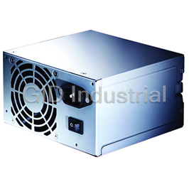
BPS BPS-250DR2/2U

Description
2U 250W + 250W 48V DC/DC Hot-Swap Redundant Power Supply with ATX Output
Part Number
BPS-250DR2/2U
Price
Request Quote
Manufacturer
BPS
Lead Time
Request Quote
Category
POWER SUPPLY
Datasheet

Extracted Text
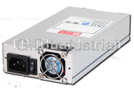
SPECIFICATION SWITCHING POWER SUPPLY VTC9595 6-OUTPUT SINGLE POWER 250W VoxTechnologies 301 S Sherman Suite 117 Richardson Texas 75081 Tel: 972-234-4343 Fax: 972-234-4295 1.0 General 1.1 Parameter Specifications 2.0 Input Characteristics 2.1 Input Voltage 2.2 Input Waveform 2.3 Input Frequency 2.4 Input Current 2.5 In-Rush Current 2.6 Line Regulation 2.7 Input Leakage Current 2.8 Isolation (Hi-Pot) 3.0 Output Characteristics 3.1 DC Output Characteristics 3.2 Overshoot 3.3 Efficiency 4.0 Time Sequence 4.1 Hold-Up Time 4.2 Power Good Signal 4.3 +5 Volt & +3.3V Power Good Output Rise Time 4.4 Start-Up Time 4.5 Dynamic Load Response Time 5.0 Protection 5.1 Over Power Protection 5.2 Over Voltage Protection 5.3 Short Circuit Protection 5.4 No Load Operation 5.5 5VSB (Standby) 5.6 PS-ON (Remote ON/OFF) 5.7 3.3V Sense 6.0 Physical Characteristics 6.1 Size 6.2 Mounting Requirements 6.3 Weight 6.4 Cooling 7.0 Connectors 7.1 DC Output Wire List 7.2 DC Input 8.0 Environmental 8.1 Temperature 8.2 Relative Humidity 8.3 Altitude 8.4 Shock 8.5 Vibration 8.6 Power Line Transient 8.7 Acoustic Noise 9.0 Regulatory Agency Certification 9.1 Safety Standards 10.0 Reliability 10.1 Mean Time Between Failures (MTBF) 10.2 Warranty 1.0 General This specification describes the physical, functional and electrical characteristics of a DC/DC single power 250 watts, 6-output, fan-cooled switching power supply. 1.1 Parameter Specifications Unless specified otherwise, all parameters must be not over the limits of temperature, load and input voltage. 2.0 Input Characteristics 2.1 Input Voltage Normal Minimum Maximum -48VDC -36 VDC -72 VDC 2.2 Input Waveform The unit is capable of operating with a 10% distorted sinewave input as measured by a distortion analyzer. Its flattopping clipped 10% from the peak value of standard sinewave. 2.3 Input current Input Power 500W Vin: -48VDC 10A 2.4 In-Rush Current CONDITIONS LIMITS -48VDC, full load. No damage shall occur or Turn off 1 sec; turn on at components over stressed, peak of input voltage cycle. input fuse shall not blow. 25 Air Ambient cold start. 2.6 Line Regulation CONDITIONS LIMITS Full load, +/1% -48VDC INPUT 2.7 Input Leakage Current Input leakage current from line to ground will be less than 3.5 mA rms. Measurement will be made at –48 VDC and 10A. 2.8 Isolation (Hi-pot) 1500VRMS, 50Hz, for one (1) minute between each input DC line and the grounding conductor. 3000VRMS, 50Hz, for one (1) Minute between the input DC lines and secondary low voltage outputs and shields. All isolation transformers will have been tested prior to assembly into a power supply unit. Any such transformers without a grounded shield will be tested to 3750 VRMS. 3.0 Output Characteristics 3.1 DC Output Characteristics To be met under all combinations of loading. Output V1 V2 V3 V4 V5 5VSB Voltage +5V 3.3V +12V -5V -12V Standby Max. Load 25A 20A 10A 0.5A 0.5A 1.5A Min. Load 3A 0A 1A 0A 0A 0A Max. Power 150W 2.5W 6W 7.5W 234W Load Reg. % +/-5% +5/-3% +/-5% +/-10% +/-10% +/-5% Cross Reg. % +/-5% +5/-3% +/-5% +/-10% +/-10% +/-5% Line Reg. % +/-1% +/-1% +/-1% +/-1% +/-1% +/-1% Ripple % +/-1% +/-1% +/-1% +/-2% +/-2% +/-1% Noise % +/-1% +/-1% +/-1% +/-2% +/-2% +/-1% Note 1: The +12 Volt output of the power supply must be capable of 15 Amps peak for 10 seconds. A +/-5% tolerance is permissible. Output voltage is measured at the load and of the output cable. Note 2: Noise bandwidth is from DC to 20 MHz. Note 3: Regulation tolerance shall include temperature change, warm up drift and dynamic load. 3.2 Overshoot Any output overshoot at TURN-ON shall not exceed 5% (+5V/+12V/+3.3V outputs) and 10% (-5V/-12V outputs) of nominal voltage value. 3.3 Efficiency 70% min. at full load test. 4.0 Time Sequence 4.1 Hold-Up Time Unit shall continue to supply regulated DC outputs and power good signal for at least 20 milliseconds at -48 VDC full loads after a loss of DC input voltage, which shall be represented by a short circuit at the DC input. 4.2 Power Good Signal When the power supply is turned off for a minimum of 1.0 second and turned on, the power-good signal as described below will be generated. The power supply shall provide a power-good signal to indicate proper operation of the power supply. This signal shall be a TTL compatible high level for normal operation; low level for fault conditions. Power-good shall go to a low level at least 1 ms before the +5V output voltage falls below the regulation limits described in 3.1 DC output Characteristics. The operation point used as a reference for measuring the 1ms shall be minimum line voltage and maximum load. All waveform transitions shall be smooth and monotony, i.e. no oscillations. The power-good signal shall stay low (during POWER-ON) until all output voltages are stable within regulation limits. The power-good signal shall have a TURN-ON delay greater than 100 ms but less than 500 ms. 4.2.1 Fan-out Power Good output circuit shall consist of an active pull down component and a passive pull up resistor. Power-Good output voltage to be met under recommended loading conditions. CONDITIONS LIMITS IoH= -140uA Min. VoH= 2.7V Min. IoL= 2.8mA Min. VoL= 0.4V Min. 4.3 +5 V & +3.3V and Power Good Outputs Rise Time 4.3.1 +5 V & +3.3V Output Rise Time The +5 Volt and +3.3 Volt output shall have a turn-on rise time of less than 100ms under all load conditions. Rise time is measured between 0.0 and 2.48/4.75 volts. The +5 V and +3.3V output shall not vary from a smooth curve by more than 0.5 VP-P during turn-on and turn-off. +5v, +3.3V 0.5Vp-p 0.5Vp-p max. max. Rise Time < 5us 2.5v P/G CV 4.4 Start-up timing All outputs shall be stable and in regulation in less then 2.0 second under all load and line conditions. Start-up time is measured between the DC turn-on and 4.75 volts on +5v output. 4.5 Dynamic Load Response Time Transient response is measured by switching the output load from 80 to 100 to 80 percent of its full value at a frequency of 100 Hz and 50% duty cycle, step load change is 0.5A/us, The magnitude Vr is less than +/- 5% of +5V and +12V outputs, the recovery time Tr is less than 1ms. 5.0 Protection 5.1 Over Power Protection This power supply shut down all DC outputs when +5 Vdc and +12 Vdc outputs are overloaded to the limit. The power supply logic shall latch into the off state requiring a power on cycle to be performed by the operator. The power supply will turn-off within 20 ms of the occurrence of the overload. The -5 Vdc and -12 Vdc outputs will be internally current limited. CONDITIONS LIMIT -48 VDC input When output power is over to 120% 5.2 Over Voltage Protection The power supply shall latch off if the +5 VDC or 3.3VDC or +12 VDC maximum voltage exceeds the limits shown. The DC must be recycled to restart. +5 VDC CONDITIONS LIMITS All operating 6.25 VDC +/- 0.65 VDC +3.3 VDC CONDITIONS LIMITS All operating 4.10 VDC +/- 0.40 VDC +12 VDC CONDITIONS LIMITS All operating 13.6 - 15.6 VDC 5.3 Short Circuit Protection A short circuit placed on any output shall cause no damage to this unit. 5.4 No Load Operation When primary power is applied, with no load on any output voltage, no damage or hazardous conditions shall occur. In such a case, the power supply shall power up and stabilize. However, minimum load required 3A for +5V and 1A for +12V. 5.5 5VSB (Standby) The 5VSB output is always on (+5V Standby) when DC power is applied and power switch is turned on. The 5VSB line is capable of delivering at a maximum of 5A for PC board circuit to operate. 5.6 PS-ON (Remote ON/OFF) PS-ON is an active low signal that turns on the entire main power rail including 3V, 5V, -5V, 12V & -12V power rails. When this signal is held by the PC board or left open circuited, outputs of the power rails should not deliver current and should be held at a zero potential with respect to ground. Power should only be delivered to the rails if PS-ON signal is held at ground potential. This signal should be held at +5VDC by a pull-up resistor internal to the power supply. Power On P1-PIN #14 Power Switch P1-PIN #14 PS-ON PS-ON ON L ON IN OFF H ON IN OFF X ON OUT OFF X OFF X 5.7 3.3V Sense A remote 3.3V sense line can be added to the P1 connector Pin2 to allow for accurate control of the 3.3VDC line directly at motherboard loads. Due to potential voltage drops across the connector and traces leading to the motherboard components, it may be advantageous to implement a 3.3V sense line that remotely monitors the 3.3VDC power level at the load on the motherboard. 6.0 Physical Characteristics 6.1 Size 100*40.5*190mm 6.2 Mounting Requirements See Figure 6 6.3 Weight 1 Kg 6.4 Cooling Fans: NMB (1608KL-04W-B50), equivalent or better. Airflow from the power supply should be in exhaust direction and shall be rated at 0.27 cfm minimum. 7.0 Connections 7.1 DC Output Wire List + For ATX Mother Board Connector Output Wire Color Wire Size P1-1 +3.3V BRN 16 AWG P1-2 +3.3V BRN 16 AWG P1-3 GND BLK 18 AWG P1-4 +5V RED 18 AWG P1-5 GND BLK 18 AWG P1-6 +5V RED 18 AWG P1-7 GND BLK 18 AWG P1-8 PW-OK ORG 18 AWG P1-9 5VSB PURPLE 18 AWG P1-10 +12V YEL 18 AWG P1-11 +3.3V BRN 16 AWG P1-12 -12V BLUE 18 AWG P1-13 GND BLK 18 AWG P1-14 PS-ON GRN 18 AWG P1-15 GND BLK 18 AWG P1-16 GND BLK 18 AWG P1-17 GND BLK 18 AWG P1-18 -5V WHT 18 AWG P1-19 +5V RED 18 AWG P1-20 +5V RED 18 AWG P11-1 +5V RED 22 AWG P11-2 COM BLK 22 AWG P11-3 COM BLK 22 AWG P11-4 +12V YEL 22 AWG P12、P13 Pn-1 +12V YEL 18 AWG Pn-2 COM BLK 18 AWG Pn-3 COM BLK 18 AWG Pn-4 +5V RED 18 AWG P14、 P15 Pn-1 +12V YEL 18 AWG Pn-2 COM BLK 18 AWG Pn-3 COM BLK 18 AWG Pn-4 +5V RED 18 AWG 7.2 DC Input 3 Pin DC/DC terminals. 8.0 Environmental 8.1 Temperature 8.1.1 Operating 50 to 122 °F (0 to 50 °C). Derate Linearly to 50% at 70 °C 8.1.2 Non-Operating -4.0 to 140 °F (-20 to 60°C) 8.2 Relative Humidity 8.2.1 Operating 20 to 90 % non-condensing at 104°F (40 °C). 8.2.2 Non-Operating 5 to 95 % non-condensing at 122°F (50°C). 8.3 Altitude 8.3.1 Operating Sea level to 10,000 feet. 8.3.2 Non-Operating Sea level to 40,000 feet. 8.4 Shock 8.4.1 Operating The power supply shall exhibit no sings of damage or degradation of performance when subjected to a shock of 5g`s for 11 ms, with a 1/2 sine wave for each of the perpendicular axes X, Y and Z. 8.4.2 Non-Operating The power supply shall exhibit no sings of damage or degradation of performance when subjected to a shock of 30g's for 11 ms, with a 1/2 sine wave for each of the perpendicular axes X, Y and Z. 8.5 Vibration 8.5.1 Operating The power supply shall be subjected to a vibration test consisting of a 10 to 500 Hz sweep at a constant acceleration of 0.5g for a duration of one (1) hour for each of the perpendicular axes X, Y and Z. The output voltages shall remain within specification. 8.5.2 Non-Operating The power supply shall be subjected to a vibration test consisting of a 10 to 300 Hz sweep at a constant acceleration of 2.0g for a duration of one (1) hour for each of the perpendicular axes X, Y and Z. The power supply shall not incur physical damage or degradation of any characteristics below the performance specifications. 8.6 Power Line Transient 8.6.1 Drop Out With a full cycle input voltage drop-out at 50Hz, the unit shall operating within the prescribed voltages with a drop-out cycle repetition rate of 500ms. CONDITIONS LIMITS Full load, Nom. Input AC Voltage Meet all requirements 8.6.2 Transient Voltage Spikes The unit shall meet the following standards, The IEEE Standard 587-1980 for surge withstand capability under categories A and B. The crest value of the first half peak of the injected Ring wave (0.5/10us) and Bi-wave (1.2/50us) will be 3K volts open circuit and 3KA (8us×20us) short circuit. IEC 801-2 (ESD) to a level of 8KV contact, and 15K air discharge without causing the device(s) to fail the test. IEC 801-4 (EFT) on the power lines and all I/O cables to a level of 2.5KV without causing the Device(s) to fail the test. IEC 801-5 Surge immunity measurement on the input power source of 2.5KV. All output shall be stable and in regulation. 8.7 Acoustic Noise The power supply shall be tested in accordance with the ANSIS12.10-1985 standard specifications. The "A" weighted overall sound pressure level as well as individual octave band levels from 63 Hz to 16,000 Hz is measured with the noise meter placed 1 meter from the nearest vertical surface of center of fan installed in power supply. CONDITIONS LIMITS 115 VAC Input, full load of +5V Acoustic noise is 40 db maximum 0.5A of +12V. Octave Band Center Frequency (Hz) A-Weighted 125 250 500 1k 2k 4k 8k 16k Max. Sum 20 36 42 42 42 36 30 20 40dBA 9.0 Regulatory Agency Certification 9.1 Safety Standards The power supply shall be certified with the following safety standards, a) UL 1950 (Information Processing/Business equipment). b) CSA C22.2, NO. 234-M90 level 6 (Safety of component, power supplies) or CSA C22.2, NO. 950-M89. st c) TUV Certification to IEC 950 1 edition with Amendment #1, #2, and EN60950 d) CB Certificate & Test report deviation for the Nordic countries. e) CE Certificate & Test report. 10.0 Reliability 10.1 Mean Time Between failures (MTBF) Using MIL217E the calculated MTBF = 100,000 hours at 25°C 10.2 Warranty Two (2) years manufacture's warranty Date code indicating week and year of manufacture.
Frequently asked questions
What makes Elite.Parts unique?

What kind of warranty will the BPS-250DR2/2U have?
Which carriers does Elite.Parts work with?
Will Elite.Parts sell to me even though I live outside the USA?
I have a preferred payment method. Will Elite.Parts accept it?


What they say about us
FANTASTIC RESOURCE
One of our top priorities is maintaining our business with precision, and we are constantly looking for affiliates that can help us achieve our goal. With the aid of GID Industrial, our obsolete product management has never been more efficient. They have been a great resource to our company, and have quickly become a go-to supplier on our list!
Bucher Emhart Glass
EXCELLENT SERVICE
With our strict fundamentals and high expectations, we were surprised when we came across GID Industrial and their competitive pricing. When we approached them with our issue, they were incredibly confident in being able to provide us with a seamless solution at the best price for us. GID Industrial quickly understood our needs and provided us with excellent service, as well as fully tested product to ensure what we received would be the right fit for our company.
Fuji
HARD TO FIND A BETTER PROVIDER
Our company provides services to aid in the manufacture of technological products, such as semiconductors and flat panel displays, and often searching for distributors of obsolete product we require can waste time and money. Finding GID Industrial proved to be a great asset to our company, with cost effective solutions and superior knowledge on all of their materials, it’d be hard to find a better provider of obsolete or hard to find products.
Applied Materials
CONSISTENTLY DELIVERS QUALITY SOLUTIONS
Over the years, the equipment used in our company becomes discontinued, but they’re still of great use to us and our customers. Once these products are no longer available through the manufacturer, finding a reliable, quick supplier is a necessity, and luckily for us, GID Industrial has provided the most trustworthy, quality solutions to our obsolete component needs.
Nidec Vamco
TERRIFIC RESOURCE
This company has been a terrific help to us (I work for Trican Well Service) in sourcing the Micron Ram Memory we needed for our Siemens computers. Great service! And great pricing! I know when the product is shipping and when it will arrive, all the way through the ordering process.
Trican Well Service
GO TO SOURCE
When I can't find an obsolete part, I first call GID and they'll come up with my parts every time. Great customer service and follow up as well. Scott emails me from time to time to touch base and see if we're having trouble finding something.....which is often with our 25 yr old equipment.
ConAgra Foods