

 Manufacturers
BASLER ELECTRIC DECS-300
Description
Basler Electric DECS-300 Digital Excitation Control System
Part Number
DECS-300
Price
Request Quote
Manufacturer
BASLER ELECTRIC
Lead Time
Request Quote
Category
REGULATION AND SYSTEMS CONTROL » VOLTAGE REGULATORS
Datasheet
Basler-Electric-DECS-300-Digital-Excitation-Control-System-datasheet1-1749222798.pdf
1027 KiB

Extracted Text
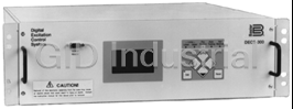
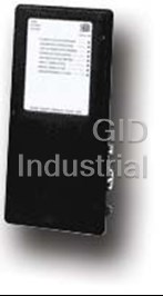
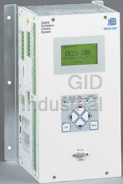
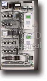
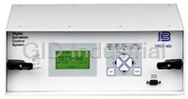
DECS-300 Digital Excitation Control System DECS-300 Digital Excitation Control System Digital Excitation Control Systems (DECS-300) are microprocessor-based devices intended for generator power management. These devices pro- vide control signals for pulse width modulated power modules and SCR bridges manufactured by Basler Electric and other manufacturers. The DECS-300 provides precision control for generators of any size and is equally suited for exciter field or main field applications. FEATURES • Microprocessor-based design True RMS sensing, single or three phase Controls the firing of external bridges by outputting 4-20mA, 0-10Vdc or ±10Vdc 0.25% Voltage Regulation Accuracy ® setup softwareSetup from front panel HMI or by PC with free Windows 40 standard stability selections DESCRIPTION and User customizable stability selection SPECIFICATIONS Paralleling compensation Pages 2 through 5 0 to 3 times Volts per Hertz Underfrequency compensation Softstart buildup FEATURES and Field Current Regulation Mode (Manual Mode) FUNCTIONS Autotracking between operating modes and between DECS-300 units Pages 6 and 7 Autotransfer to a back-up DECS-300 unit Remote setpoint control via: INTERCONNECT - Contact inputs - Proportional control via ±3Vdc, 0-10Vdc, or 4-20mA DIAGRAMS - Communications inputs RS-232 (ASCII) or RS-485 (Modbus™) Pages 8 and 9 Minimum Excitation Limiter On and off-line Maximum Excitation Limiters FRONT, REAR VIEWS VAR and Power Factor Controllers (continued on next page) and DIMENSIONS Pages 10 and 11 ® WINDOWS SOFTWARE Interface for setting and communicating with Basler products Request BESTCOMS™-DECS300-32 ® ® ® CUTOUT and ORDERING (Windows NT 3.51 or later, Windows 95, or Windows 98) Page 12 ADDITIONAL INFORMATION INSTRUCTION MANUAL Request Publication 9310300990 SZE-3 8-00 P. O. BOX 269 HIGHLAND, ILLINOIS, U.S.A. 62249 PHONE 618-654-2341 FAX 618-654-2351 DECS-300 Digital Excitation Control System FEATURES, continued Voltage MatchingModbus™ protocol for RS-485 input allows communications up to 4000 feet away 4 generator protection features <1% metering accuracy for 12 generator parameters Programmable output contacts Meets C37.90.1-1989 for Surge Withstand and Fast Front panel backlit LCD display Transient Front panel mounted RS-232 and rear-mounted UL Recognized and CSA Certified RS-485 communications ports U.S. Patent Number 5,294,879 DESCRIPTION allows the nonactive control mode, within the unit, to The DECS-300 is a microprocessor based excitation follow the active mode, permitting bumpless transfer controller. It provides output control signals to control between modes. The software also allows for unit-to- the firing (output) of an external power bridge. The unit communication, permitting autofollowing and DECS-300 is designed to work with Basler Electric's transfer between DECS-300 units. It can also commu- SSE and SSEN power bridges, but will work equally nicate to a PC via the front panel RS-232 port for local well with any power bridge suitable for use on a programming and metering, and it can communicate synchronous generator/motor that has a firing circuit via Modbus™ protocol via the rear-mounted RS-485 capable of accepting the control signal output from the port for communications up to 4000 feet away from the DECS-300. The DECS-300 is a total excitation control DECS-300 unit. The DECS-300 has all the features, system in one 19 inch rack mount enclosure. It con- functionality, flexibility and programmability expected tains all the functionality necessary to limit, control and from a state-of-the-art microprocessor based product. protect a generator from operating outside of the machine's capability. DECS-300's sophisticated design APPLICATIONS The DECS-300 is an excitation control system used to control the output voltage, VARs or Power Factor of a synchronous generator by varying or controlling the amount of dc excitation applied to either the generator's main field or exciter field. The DECS-300 is suitable for virtually any kW size machine. SPECIFICATIONS INPUTS Power Input DECS-300-L: 24/48Vdc nominal (16-60Vdc), Burden=30W. DECS-300-C: 120Vac nominal (85 to 132Vac, 50 or 60Hz), Burden=5VA. 125Vdc nominal (90 to 150Vdc), Burden=30W. Generator Voltage Sensing Single-phase or three-phase line voltage, two ranges: 100V/50Hz nominal (85 to 127V), 120V/60Hz nominal (94 to 153V) 200V/50Hz nominal (170 to 254V), 240V/60Hz nominal (187 to 305V) Bus Voltage Sensing Single-phase line voltage (AC), two ranges: 100V/50Hz nominal (85 to 127V), 120V/60Hz nominal (94 to 153V) 200V/50Hz nominal (170 to 254V), 240V/60Hz nominal (187 to 305V) Generator Current Sensing Two ac current sensing ranges and two channel (phase) inputs 1A, phase B; 1A, phases A or C 5A, phase B; 5A, phases A or C 2 DECS-300 Digital Excitation Control System SPECIFICATIONS, continued Sensing Burden Voltage: Less than 1VA per phase. Current: Less than 1VA. Parallel Compensation: Less than 1VA. Contact Switching Inputs Thirteen contact switching inputs are supplied with 24Vdc to accommodate dry contacts. Contacts are as follows: Start VAR/PF Enable Stop Pre-position Autotransfer Enabled Raise Switch Unit/Parallel Operation Lower Switch Autotrack Enable General Purpose Switch #1 AVR Mode General Purpose Switch #2 FCR Mode Remote Setpoint Control Two separate analog inputs for remote setpoint control (select one from the (Accessory Input) configuration menu) ±10Vdc 4 to 20 milliamperes OUTPUTS Control Outputs Two analog outputs for setpoint control (select one from the configuration menu) ±10Vdc or 0 to +10Vdc 4 to 20 milliamperes Contact Outputs Make and carry for 30 amperes for 0.2 seconds per ANSI C37.90; continuous for 7 amperes tripping duty Break resistive or 0.3 amperes at 125 or 250Vdc (L/R=0.04 maximum). inductive Eight output contacts rated as described with 300 volt surge suppressors in- stalled across contacts to prevent arcing from inductive loads. Contacts are as follows: Buildup Relay #4 Fail-to-flash Relay #3 Watchdog Relay #2 Start/Stop Relay #1 ISOLATION MODULE Operating voltage + and - 12Vdc from DECS-300. (Isolation module and case Five field voltage sensing ranges: 32, 63, 125, 250 and 375 volts are included with DECS-300) Field analog output signal: 0.9 to 9.1Vdc(5.0Vdc=0 field voltage) Two field current sensing ranges: 50 and 100 millivolts. Field analog output signal: 2.0 to 9.5Vdc (2.0Vdc=0 field current) COMMUNICATION There are three communication ports, two RS-232 and one RS-485. COM0: RS-232, 9 pin, sub-D connector located on front panel and used to communicate with local computers. 1200 to 19200 baud, 8N1 full duplex, ASCII commands COM1: RS-232, 9 pin, sub-D connector located on rear panel and used to connect primary and backup DECS-300 units or other devices. 1200 to 19200 baud, 8N1 full duplex, unique ASCII commands, only used for autotracking 3 DECS-300 Digital Excitation Control System SPECIFICATIONS, continued COM2: RS-485, located on rear panel and used to communicate with local or remote computers or other devices. 1200 to 19200 baud, 8N1 half duplex, Modbus™ protocol REGULATION ACCURACY AVR Mode Voltage regulation equals ±0.25% over the load range at rated power factor and constant generator frequency. Steady state stability equals ±0.1% at a constant load and generator frequency. Temperature drift equals ±0.5% for 0 to 50°C temperature change. Underfrequency (volts/hertz) characteristic slope from 0 P.U. to 3.0 P.U. is adjustable in 0.1 P.U. increments. Voltage regulation error is within ±2.0% of the nominal voltage. FCR Mode Field current regulation equals ±1.0% of the nominal value for 10% of the bridge input voltage change or 20% of the field resistance change. Otherwise, ±5.0%. VAR Mode ±2.0% of the nominal VA rating at the rated frequency. PF Mode ±0.02 PF in the setpoint PF for the real power between 10 and 100% at the rated frequency. (e.g. -setpoint PF = 0.80, PF regulation is from 0.78 to 0.82 PF.) Autotracking ±0.5% of the nominal field voltage change when transferring. PARALLEL COMPENSATION Can use either reactive droop or reactive differential (cross-current) compensation. Adjustable 10% of the rated generator voltage droop with optional 1 ampere or less or 5 amperes or less input. For parallel compensation, burden is less than 1VA. FIELD OVERVOLTAGE Adjustable in increments of 1.0Vdc from 1.0 to 900Vdc rated output voltage with PROTECTION a 0.2 to 30 second inverse time delay settable in increments of 0.1 second. FIELD OVERCURRENT Adjustable in increments of 0.1% steps of rated field current from 0 to 9999Adc PROTECTION excitation current setting with an inverse time delay (ANSI C50.13). GENERATOR UNDERVOLTAGE Adjustable in increments of 1 from 0 to 30kV sensing voltage setting with a 0.5 PROTECTION to 60 second inverse time delay (ANSI C50.13) settable in increments of 0.1 second. GENERATOR OVERVOLTAGE Adjustable in increments of 1 from 0 to 30kV sensing voltage with a 0.1 to 60 PROTECTION second inverse time delay (ANSI C50.13) settable in increments of 0.1 second. LOSS OF SENSING The loss of sensing is factory set at 50% of nominal. The time delay is adjustable for 0-30 seconds in 0.1 second increments. SOFT-START Functional in AVR and FCR with an adjustable rate of 1 to 200 volts per second in AVR, and 1 to 33% of the manual setpoint per second. 4 DECS-300 Digital Excitation Control System SPECIFICATIONS, continued OVEREXCITATION LIMITING Limiter response time is less than three cycles. On-Line Level One - Highest current level (instantaneous) setpoint adjustable from 0 to 9999Adc in 0.1% increments of the rated field current. Limiting occurs for a time period ranging from 0 to 60 seconds, settable in 1 second increments Level Two - Medium current level setpoint adjustable from 0 to 9999Adc in 0.1% increments of the rated field current. Limiting occurs for a time period ranging from 0 to 120 seconds, settable in 1 second increments. Level Three - Lowest current level setpoint adjustable from 0 to 9999Adc in 0.1% increments of the rated field current. Limiting occurs indefinitely. Off-Line Level One - Highest current level setpoint adjustable from 0 to 9999Adc in 0.1% increments of the rated field current. Limiting occurs for a time period ranging from 0 to 60 seconds, settable in 1 second increments. Level Two - Lowest current level setpoint adjustable from 0 to 9999Adc in 0.1% increments of the rated field current. Limiting occurs indefinitely. UNDEREXCITATION Adjustable from 0-100% maximum reactive current LIMITING MANUAL EXCITATION Regulates field current from 0 to 5000A in increments of 0.1% of the rated output CONTROL current VOLTAGE MATCHING Matches utility bus RMS voltage with generator output RMS voltage within ±0.15% of the generator voltage RFI (Radio Frequency Meets IEC 60255-22-6 (RF Conducted) and IEC 60255-22-3 (Radiated Electro- Interference) magnetic Field) FAST TRANSIENT Meets IEC 60255-22-4 EMISSIONS Meets CISPR11/EN55011 Level A ENVIRONMENTAL Operating temperature -40°C to +60°C Storage temperature -40°C to +85°C Shock 15 Gs in each of three mutually perpendicular planes Vibration 2Gs at 10 to 500Hz Size 19 inch rack mount, 3 rack units high Weight 13.5 lb. (6.12kg) net, 17 lb. (7.71kg) shipping 5 DECS-300 Digital Excitation Control System FEATURES/FUNCTIONS Voltage Regulation levels during start-up of the generator system. The DECS-300 regulates the generator RMS voltage to within 0.25% from no-load to full-load. It does this by Paralleling Compensation utilizing digital signal processing and precise regula- DECS-300 has provisions to parallel two or more tion algorithms developed by Basler Electric and generators using reactive droop or reactive differential utilizing the experience gained in many years of compensation with the addition of an external current manufacturing tens of thousands of digital voltage transformer with secondary currents of 1 or 5Aac. The regulators. current input is rated at less than 1VA. This low burden means that existing metering CTs can be used and Output Signals dedicated CTs are not required. The DECS-300 sends an output signal of 4-20mA, 0-10Vdc or ±10Vdc to the firing or control circuits of Setpoint Control external power stages. The dc current from the power DECS-300 has means for external setpoint adjustment stages provides excitation to the field of the main of the controlling mode of operation. This eliminates generator or exciter. DECS-300 can control virtually the need for additional equipment like motor operated any bridge, capable of accepting these signals, that is pots for remote control or multiple point control for the suitable for use on synchronous generators/motors. excitation system. The operating mode's setpoint may be directly controlled by raise/lower contact inputs, Stability auxiliary inputs of 4-20mA or ±10Vdc. The auxiliary The DECS-300 utilizes proportional (P), integral (I) and input adjusts the operating mode across its predeter- derivative (D) stability control. DECS-300 has 40 mined adjustment range. The auxiliary input can be preprogrammed stability (PID) settings for both main provided from other controlling devices such as a field (20 settings) and exciter field (20 settings) appli- power system stabilizer. These devices modify the cations. This means that a standard stability setting is operation of the DECS-300 to meet specific operating already available for most applications/machines. The characteristics and requirements for the machine under DECS-300 has a stability range that allows for custom- DECS-300 control. The third method of setpoint control izing the stability settings to fine tune the stability to is via the RS-232 communication ports by using the ® provide optimum customized generator transient Windows 95 based PC software or via Modbus™ performance. Setup software contains PID selection protocol and the rear-mounted RS-485 port. Regard- program to assist in determining the correct PID less of which method of setpoint is used (contact settings. The DECS-300 provides for customizing the inputs, auxiliary input or communications with a PC or stability and transient performance of the Min/Max PLC), traverse rates of all modes of operation are Excitation Limiter and VAR/PF controllers by providing independently adjustable. This means an operator can additional stability adjustments. customize the rate of adjustment and "feel" to meet his/her needs. Underfrequency Compensation DECS-300 provides the ability to customize the Pre-position Inputs underfrequency setting to precisely match its perfor- DECS-300 provides the added flexibility of allowing a mance to the prime movers. The frequency compensa- predetermined operating point for each mode of tion can be selected to have 0 to 3 times Volts/Hertz, in operation. With a contact input to the DECS-300, the 0.1V/Hz increments and the frequency roll-off operating mode is driven to an operating or regulation kneepoint can be set across a range of 45 to 65Hz in level assigned to that operation mode by the operator 0.1Hz increments. This adjustability allows the DECS- or user. The pre-position inputs operate in one of two 300 to be precisely matched to the operating charac- modes, Maintain or Release. The Maintain mode teristics of the prime mover and the loads being prevents adjustment of the setpoint as long as the pre- applied to the prime mover/generator. position contact is closed. The release mode allows adjustment of the setpoint even though the pre-position Softstart Voltage Buildup is closed. This feature allows the DECS-300 to be Generator voltage overshoot can be harmful to the configured for specific system and application needs. generator's insulation system if not controlled. DECS- 300 has a softstart feature with a user-adjustable Field Current Regulation Operating Mode setting to govern the rate at which the generator DECS-300 provides a manual channel of operation voltage is allowed to build up. This prevents the called Field Current Regulation, or FCR, Mode. In this generator voltage from overshooting nominal voltage mode, DECS-300 regulates the DC output current of 6 DECS-300 Digital Excitation Control System FEATURES/FUNCTIONS, continued the power bridge. It does not rely on the sensing input the first. In the unlikely event of a failure of the first to DECS-300 and is, therefore, a good source of DECS-300, protective relays can initiate a transfer of backup excitation control when loss of sensing is control from the first to the second DECS-300. detected. In this mode, control of the generator is totally dependent upon the operator to maintain Autotransfer Input nominal generator voltage as the load varies on the This input provides a means for initiating the transfer generator. from the operating mode of the DECS-300 unit to the manual mode of operation. This facilitates transfers VAR/Power Factor Controller Operating Mode initiating from some external protective relay and DECS-300 has, as another standard feature, two avoids the use of costly auxiliary relays used on most modes of operation when the generator is in parallel analog systems. with the utility power grid. The DECS-300 has both VAR and PF modes of operation. When the generator Protective Functions is in parallel with the utility grid, the DECS-300 can There are several protection functions built into the regulate the VAR output of the generator to a specific DECS-300 unit. These functions may be used as VAR level magnitude or it can vary the VAR output of backup to the primary protection relays and can be the generator to maintain a specific power factor as the assigned to up to four programmable output contacts kW load varies on the generator. via the PC software. The protection features offer fully adjustable tripping levels and time delays. The protec- Maximum Excitation Limiters tive features are as follows: Each DECS-300 has integrated over/underexcitation Generator Overvoltage limiters. Overexcitation limiters are present for both on- Generator Undervoltage line and off-line excitation levels. This feature provides Field Overvoltage maximum overexcitation protection by having different Field Overcurrent settings for off-line operation where load levels require Watchdog Timer lower levels of excitation. When lower excitation levels Loss of Sensing are needed, lower limiter settings are required to properly protect the generator. Communications ® DECS-300 comes complete with Windows 95 based PC software. This software makes the programming Minimum Excitation Limiter The minimum excitation limiter limits the amount of and customization of the DECS-300 easy and fast. The excitation supplied to the field of the generator from software comes with a PID selection program that dropping below unsafe operating levels. This prevents allows the user to select stability settings quickly and the machine from possibly slipping poles and from easily in a user-friendly format. The PC software has a damaging the machine. It limits the VAR low from the special monitoring function that allows the user to view machine to a preset level of between 0 and 100% of the all settings, a metering screen for viewing all machine machine's VAR capability. parameters, and a control screen for remote control of the excitation system. Autotracking Between DECS-300 Operating Modes DECS-300 is an intelligent device that can provide The rear-mounted RS-485 port supports Modbus™ autotracking (autofollowing) of the controlling mode by communications protocol. This is an open protocol with the non-controlling modes. This allows the operator to all registers and operating instructions available in the initiate a controlled, bumpless transfer of the DECS-300 instruction manual, to make it simple for the user to operating modes, causing minimum amounts of line develop custom communications software. disturbance for the power system. This feature can be used in conjunction with a set of protective relays to Password Protection initiate a transfer to a backup mode of operation, such All DECS-300 parameters are viewable via the front as FCR mode, upon the detection of a system failure or panel LCD display, the PC software or via Modbus™ fault, i.e., loss of sensing. without the need of a password. If the user wishes to change a setting, the proper password must be Autotracking Between DECS-300 Units entered to allow access to the parameter. Two levels of A DECS-300 can also follow (autotrack) a second password protection exist, one for global access of all DECS-300 unit. The first DECS-300 is put into a spe- parameters and one for a limited amount of access to cific operating mode and follows the excitation level of parameters normally associated with operator control. 7 DECS-300 Digital Excitation Control System CONNECTIONS Figure 1 - Typical AC Connection Diagram 8 DECS-300 Digital Excitation Control System CONNECTIONS, continued Figure 2 - Typical DC Connection Diagram 9 DECS-300 Digital Excitation Control System FRONT and REAR PANEL VIEWS The front panel HMI (Human Machine Interface) is composed of several elements, including a backlit LCD screen, six pushbuttons and six LEDs. The LCD is the primary interface because it conveys the majority of the information between the DECS-300 and the user/operator. Front panel pushbuttons allow the user to view menu screens and modify the various screen settings and operating conditions. The LEDs annunciate their respective states. A) 64x128 pixel graphic LCD with backlighting. Primary source for receiving information from the DECS or when locally programming settings. Displays operations, setpoints, loop gains, metering, protection functions, system parameters and general settings. B) Null Balance LED – Turns ON when the inactive modes (AVR, FCR, VAR, or PF) match the active mode. C) Autotracking LED – All inactive modes (AVR, FCR, VAR, or PF) track the active mode to accomplish the bumpless transfer when changing active modes. D) Pre-Position LED – Turns ON at the predefined setting (within the limits of the setpoints) of the current mode. E) Lower Limit LED – Turns ON at the minimum setpoint value of the current (active) mode. F) Upper Limit LED – Turns ON at the maximum setpoint value of the current mode. G) Reset Pushbutton – Cancels editing sessions and can be used as a quick-access to the metering screen. H) Scrolling Pushbuttons – Scrolls UP/DOWN/LEFT/RIGHT through the menu tree or when in the EDIT mode, the LEFT/RIGHT scrolling pushbuttons select the variable to change and the UP/DOWN scrolling pushbuttons change the variable. I) Edit Pushbuttons – Enables settings changes. When the EDIT pushbutton is first pushed, an LED on the pushbutton turns ON to indicate the edit mode is active. When changes are complete (using the scrolling pushbuttons) and the EDIT pushbutton is pushed again, the LED turns OFF, indicating the changes are saved. If changes are not completed and saved within five minutes, the edit mode is exited without saving changes. J) Serial Port COM0 – D-type 9 pin connector. This port is dedicated to RS-232 (ASCII commands) communica- tion with a computer terminal or PC running a terminal emulation program such as BESTCOMS™. Figure 3 - Rear Panel View 10 DECS-300 Digital Excitation Control System DIMENSIONS Front view Top view Side view Isolation Module Figure 4 - Dimensions 11 DECS-300 Digital Excitation Control System CUTOUT/MOUNTING INFORMATION Figure 5 - Front Panel Cutout Dimensions (Optional front panel mounting bracket, Basler P/N 9310304100) HOW TO ORDER The DECS-300 is available in one of two power supply ranges. Model number designations are shown below. Model Power Supply DECS-300-L 24/48 Vdc DECS-300-C 120/125 Vac/Vdc ACCESSORIES Front panel mounting bracket, Basler P/N 9310304100. Interconnection cable for dual DECS-300 applications, Basler P/N 9310300032. RDP-300 Remote Display Panel (shown on right), is a Human-Machine Interface (HMI) used to provide remote control, view metered quantities, and provide annunciation of system status and alarms available from the DECS-300 system. The RDP-300 features a touch-sensitive 6" diagonal monitoring screen, two- wire RS-485 Modbus™ communication protocol, and may be located up to 4000 feet away from the DECS-300. For more details, see Product Bulletin SNE. ROUTE 143, BOX 269, HIGHLAND, ILLINOIS U.S.A. 62249 P.A.E. Les Pins, 67319 Wasselonne Cedex FRANCE PHONE 618-654-2341 FAX 618-654-2351 PHONE (33-3-88) 87-1010 FAX (33-3-88) 87-0808 http://www.basler.com, info@basler.com
Frequently asked questions
What makes Elite.Parts unique?

What kind of warranty will the DECS-300 have?
Which carriers does Elite.Parts work with?
Will Elite.Parts sell to me even though I live outside the USA?
I have a preferred payment method. Will Elite.Parts accept it?


What they say about us
FANTASTIC RESOURCE
One of our top priorities is maintaining our business with precision, and we are constantly looking for affiliates that can help us achieve our goal. With the aid of GID Industrial, our obsolete product management has never been more efficient. They have been a great resource to our company, and have quickly become a go-to supplier on our list!
Bucher Emhart Glass
EXCELLENT SERVICE
With our strict fundamentals and high expectations, we were surprised when we came across GID Industrial and their competitive pricing. When we approached them with our issue, they were incredibly confident in being able to provide us with a seamless solution at the best price for us. GID Industrial quickly understood our needs and provided us with excellent service, as well as fully tested product to ensure what we received would be the right fit for our company.
Fuji
HARD TO FIND A BETTER PROVIDER
Our company provides services to aid in the manufacture of technological products, such as semiconductors and flat panel displays, and often searching for distributors of obsolete product we require can waste time and money. Finding GID Industrial proved to be a great asset to our company, with cost effective solutions and superior knowledge on all of their materials, it’d be hard to find a better provider of obsolete or hard to find products.
Applied Materials
CONSISTENTLY DELIVERS QUALITY SOLUTIONS
Over the years, the equipment used in our company becomes discontinued, but they’re still of great use to us and our customers. Once these products are no longer available through the manufacturer, finding a reliable, quick supplier is a necessity, and luckily for us, GID Industrial has provided the most trustworthy, quality solutions to our obsolete component needs.
Nidec Vamco
TERRIFIC RESOURCE
This company has been a terrific help to us (I work for Trican Well Service) in sourcing the Micron Ram Memory we needed for our Siemens computers. Great service! And great pricing! I know when the product is shipping and when it will arrive, all the way through the ordering process.
Trican Well Service
GO TO SOURCE
When I can't find an obsolete part, I first call GID and they'll come up with my parts every time. Great customer service and follow up as well. Scott emails me from time to time to touch base and see if we're having trouble finding something.....which is often with our 25 yr old equipment.
ConAgra Foods