

 Manufacturers
BASLER DECS-2100
Description
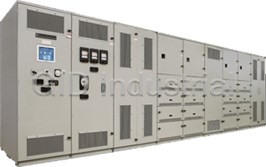
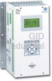
Basler DECS-2100 Digital Excitation Control System
Part Number
DECS-2100
Price
Request Quote
Manufacturer
BASLER
Lead Time
Request Quote
Category
PRODUCTS - D
Features
- Continuous current levels up to 10,000Adc
- Dual settings groups for all control modes
- Expandable inputs and outputs
- Extensive generator protection/limiting package with online and offline settings
- Field forcing options up to 1,500Vdc
- Integrated autosynchronizer (optional)
- Integrated PSS (optional)
- IRIG-B and NTP provisions for time synchronization
- Multi-microprocessor based controller
- Multiple communications/methods include: RJ-45 Ethernet, RS-485, USB, and RS-232
- Patented electronic rectifier bridge paralleling algorithm
Datasheet

Extracted Text
DECS-2100 Digital Excitation Control System DECS-2100 Digital Excitation Control System APPLICATION The DECS-2100 is the next generation multi-microprocessor digital excitation control system that provides advanced technology to precisely control, protect, and monitor synchronous generators and motors, for new and existing applications that are driven by all types of prime movers, such as steam, gas, hydro, and diesel. Its multifunctional design allows the DECS-2100 to operate as a voltage regulator or as a static exciter, providing excitation currents up to 10,000 Adc on systems ranging from 1 to 1300 MW. PRODUCT DESCRIPTION FEATURES Page 2 • Multi-Microprocessor based DECS-2100 Digital Excitation Control System ±0.1% Voltage Regulation Accuracy Control Modes with Auto-following and Dual Gain Settings AVR FUNCTIONAL VAR DESCRIPTION PF Pages 2 through 12 Manual (Field Current and Voltage) Dual Channel and Dual Channel with Supervisory Control (options) Six-SCR Power Rectifier Bridges - Fixed and Drawer Type (options) Control Channel Options Power drawers with online maintenance capabilities in an N+1 configuration Pages 3 and 4 Multi-Bridge paralleling configurations up to 10,000 Adc Power Section Description Field forcing levels up to 1500 Vdc Page 5High Initial Response Per IEEE 421.2 Patented Rectifier Bridge Active Temperature Balance Algorithm System Operation Integrated Dual Input Power System Stabilizer IEEE Type 2 (optional) Pages 4 and 5 Negative Field Forcing for best system performance High-Side Voltage Regulation Mode Hardware/Software Multiple protection and limiting functions with on-line and off-line settings Pages 5 and 6 Built-in Exciter/Main Field Ground Protection (64F) Interactive Display Panel (IDP-1200) for local and/or remote monitor and control Control Functions BESTCOMS™Pro, an extremely flexible software configuration program for Pages 6 and 7 setup and testing Protection Real-Time Monitoring of up to 6 parameters Sequence of Events (SOE) Recording Page 7 Simulation mode for configuration and testing Limiters Auto-Synchronizing (optional) Pages 7 through 9 Auto-Tuning feature calculates preliminary gain settings Multi-Port Ethernet communication capability Interface and Software IRIG-B time synchronization Features USB communication allows for removable storage media up/download Pages 9 and 10 61850 Protocol Compliance (optional) Programmable input/output terminations Programmable Sequencing provisions ECB-1 1-12 12570 STATE ROUTE 143, HIGHLAND, ILLINOIS 62249 USA PHONE 618-654-2341 FAX 618-654-2351 DECS-2100 Digital Excitation Control System DESCRIPTION converter or multiple converters operate with single-channel The Basler DECS-2100 Digital Excitation System is designed or multi-channel control logic for increased reliability. to provide digital voltage regulation, control, protection, and monitoring functions for a synchronous generator or motor. It Operator control can be provided through a single-cable achieves high levels of performance through a multiple interconnection to a local and/or remote Interactive Display microprocessor-based platform using digital signal Panel (IDP-1200), interface to PLC, SCADA, plant DCS (Distributed Control System), or traditional discrete switches processing for required computational speed of advanced and meters. control functions and algorithms. The DECS-2100 can be scaled to generation units of all sizes with minimal changes Power to the DECS-2100 can be supplied via a power except to the power electronics and the excitation power potential transformer (PPT) from the generator terminals with potential transformer. Its software tool, BESTCOMS™Pro, is field flashing for black start applications. Alternately, power used to change settings for the various limiting and to the DECS-2100 Digital Excitation Conrol System can be protection functions, download new system firmware, and taken from a reliable three-phase, 50 or 60 Hz station retrieve diagnostic information. auxiliary source or from a Permanent Magnet Generator (PMG) with a frequency up to 500 Hz. The Basler system consists of one or more thyristor power converters, each with its own digital firing control. A single Figure 1 - Typical Dual Channel Five Power Drawer DECS-2100 STANDARD SYSTEM FUNCTIONAL DESCRIPTION General DIGITAL VOLTAGE REGULATOR CHANNEL CONTROL The design of the DECS-2100 Digital Excitation System LOGIC (HARDWARE) creates flexibility in the system architecture to be better suited in meeting all the needs of your most stringent Excitation Control Module (ECM-2) applications. Proposed configurations include a single- The Excitation Control Module (ECM-2) is the next channel system and alternatives for a dual-channel or three- generation of optimal performance, flexibility, and reliability channel system with each type of system capable of using of excitation control systems packaged in a single controller. redundant power converters. The cabinet lineup includes a The ECM-2 contains the intelligence to implement all of the logic cabinet and the required number of cabinets for the regulators, limiters, protection, communication, and system power converters and auxiliary devices. See Fig. 1. It should functions, along with integrating the firing command and be noted that not all items will be utilized in all applications; sensing/metering input quantities for precise control. therefore, some components may only be applicable to certain applications. It is recommended to discuss specific Each system utilizes one ECM-2 module per channel. The options with Basler Electric’s Application Specialists. function of a module as a main controller or a redundant 2 DECS-2100 Digital Excitation Control System STANDARD SYSTEM FUNCTIONAL DESCRIPTION controller is selectable in the software of its microprocessors. The software functions/settings are stored in nonvolatile flash memory. ECM-2 modules in dual channel or with supervisory configuration also offer protection schemes to detect or announce when failures occur from within or outside the excitation system to aid troubleshooting and recovery time. The ECM-2 has the capability to synchronize the system clock using either Network Time Protocol (NTP) or IRIG-B time code format and standards within 1ms, with any failure to synchronize indicated by alarm status. The ECM-2 generates a firing command signal while gathering signals from the Field Isolation Transducers (FIT) for field voltage and the excitation transformer (PPT) secondary voltage. Each module contains 24 analog-to-digital converters for taking measurements from these transformers and other inputs. Fiber optic connections are made from the ECM-2 to expansion lower-speed analog (AIOM) and digital (DIOM) input/output modules. Figure 3 - DECS-2100 One-Line Diagram, Dual Channel Control Scheme CONTROL CHANNEL OPTIONS Dual-Control Channel with Supervision Each ECM-2 control channel with redundant power supply The three-channel system consists of the dual-channel interfaces through fiber optic cable to the firing control of one configuration plus a third channel that supervises the other or more thyristor power converters. Each power converter is two. All three channels monitor limiting and protection equipped with its own Bridge Control Module (BCM) that functions. When conditions call for a unit trip, the combined provides digital firing pulses. See Fig. 2. logic of the three controllers using two-of-three voting logic determines when the unit is tripped. This two-out-of-three voting process with the third channel (Supervisory) is also used to determine which of the dual channel controllers is selected to be in control and regulate the generator's output. POWER SECTION DESCRIPTION Digital Firing Logic Digital firing control of the thyristor bridges in the DECS- 2100 utilizes field programmable gate arrays that are supervised by a microprocessor with diagnostic capabilities located on each Bridge Control Module (BCM). Monitoring functions of each BCM include the conduction of thyristors, the temperature of the bridge, and a magnitude of bridge current feature. Each power converter is a three-phase, six-pulse, thyristor- controlled full converter whose ac input line frequency can Figure 2 - DECS-2100 One-Line Diagram, be in the range of 5 to 500 Hz. A range of Power Converters Single Channel Control Scheme are available to accommodate excitation forcing require- ments up to 1500 Vdc. Dual-Control Channel System Should the internal diagnostics in the main channel detect a Analog Firing Output The ECM-2 also contains analog firing capability via two failure, an external relay will be energized, which in turn will channels to provide 4-20 ma or ±10 Vdc output signals for direct the BCM to ignore the control signal from the other channel. A remote switch may be used to transfer control firing of external bridges. from the main to redundant channel for maintenance. See Fig. 3. 3 DECS-2100 Digital Excitation Control System STANDARD SYSTEM FUNCTIONAL DESCRIPTION, continued Active Temp Balance SYSTEM OPERATION The patented active temp balancing algorithms (known as “Skip Firing”) are preferred for multi-bridge schemes. By Regulation Modes monitoring the temperature of each SCR in the Power A variety of feedback control functions can be implemented Converter, this special algorithm facilitates an electronic to hold the particular regulated quantity at a set point. The method for rectifier bridge current firing. This unique ap- set point is adjustable by operator action. The regulator proach allows total excitation currents to reach up to 10,000 gain, range of the set point, and the slew rate of the set point Adc continuously, and helps ensure a long life expectancy are adjustable for all regulators. Transient gain reduction is for each of the power components. included with each regulator channel for the static applica- tions and Proportional, Integral, and Derivative (PID) gain Power Redundancy control is also available. The DECS-2100 is configured to optionally add an addi- tional operating power converter (N+1 configuration) and There are four regulation modes of operation that can utilize associated BCM. the various feedback control functions. Automatic Voltage Regulation Mode Although fixed designs are available, the preferred power In this mode, the DECS-2100 maintains the generator’s converter bridge design is constructed of drawout, compact voltage to <0.1% of the set point from no load to full load module subassemblies that can be electrically isolated to of the generator. High-side voltage regulation mode is facilitate maintenance under full load (in an N+1 configura- also available with some configurations. tion). This permits easy removal of a complete power Manual Regulation Mode – Generator/Exciter Field converter for repair. These modular bridges are stacked to Current limit the cubicle floor space required for the DECS-2100 When the system is in this mode, the generator/exciter Digital Excitation Control System. field current is regulated by the DECS-2100 to within ±0.5% of the generator/exciter field current (5% no-load Thyristor Protection to 125% full-load). RC snubber networks protect the thyristors against exces- Manual Regulation Mode – Generator/Exciter Field sive rate of change of current and voltage. Nonlinear resistor Voltage assemblies protect against excessive transient reverse When the system is in the Manual Regulation-Generator/ voltage. For large static exciter systems, ac line filters are Exciter Field Voltage mode, generator/exciter field typically used. Thyristor overtemperature is monitored by voltage is held to within ±0.5% of the generator/exciter field voltage (5% no-load to 125% full-load). thermal sensors (RTD’s) embedded in the heatsinks. VAR Control Mode In VAR Control mode, the system maintains the average VAR output of the generators output within ± 0.5% for -100% to +100% of the MVA rating. Power Factor Control Mode In Power Factor (PF) Control mode, the system holds the average power factor within ±0.5% for -0.5 to -1.0 leading and 0.5 to 1.0 lagging. Operating Mode Set Point Followers The Set Point Followers function provides a virtually bumpless change in the newly regulated quantity when a transfer is made from automatic voltage regulation to manual regulation and from manual regulation to automatic regulation under steady conditions. Figure 4 - 1100 Adc Power Drawer The var/power factor controller takes raise or lower signals Cooling System and generates the referenced set point for the automatic var/ For drawout converters, a main fan with a backup fan power factor regulator. The adjuster followers (when supplies forced-air cooling. An automatic fan transfer circuit enabled) operate to raise or lower this reference set point is included should the main fan fail and the fan assembly is until the difference between the automatic voltage regulator designed to allow for removal under load. and automatic var/power factor regulator error signals is within a desired deadband. Programmable Sequence Control (PSC) Programmable Sequence Control (PSC) is the BESTCOMS™Pro software function that performs startup, running, and shutdown control of the DECS-2100 Digital Excitation Control System. 4 DECS-2100 Digital Excitation Control System STANDARD SYSTEM FUNCTIONAL DESCRIPTION, continued HARDWARE AND SOFTWARE FEATURE DESCRIPTION reduces the field excitation to zero. Upon opening the ac field contactor, the remaining field energy will be dissipated Digital I/O Module (DIOM) very rapidly in a nonlinear resistor permanently connected The purpose of the Digital Input / Output Module (DIOM) is to across the field. provide a means to interface the DECS-2100 excitation control system with external devices. Each DIOM has the De-excitation Module (DX) capability to sense twelve digital inputs (±24 - 125 Vdc or The DX module is a thyristor-controlled circuit that provides 120 Vdc). an alternate path for the generator field current when the normal path is not available. The normal path is through the PPT, 41 A-supply breaker, and the generator field. To Eight digital form C relay outputs are also provided on each module. The digital outputs are each connected to form C provide the alternate path, the DX thyristor is triggered by a relays with ratings of 10 A, 120 Vac or 10 A, 30 Vdc. These control signal and/or excessive negative field voltage. outputs are used to drive external relays and indicator lights, or to interface with DCS’s and PLC’s. Each DECS-2100 Crowbar Module (CB) Generator pole slip is a source of positive high voltage. The control channel may be equipped with a maximum of four DIOMs that are connected using an isolated bi-directional Crowbar module (CB) with series resistor protects the fiber optic communication link. Utilizing the generator field and exciter power converter from excessive BESTCOMS™Pro software, the digital input and output data high positive field voltages. The Crowbar self-triggers any can be connected to any control software block input or time a high voltage occurs. The system automatically recovers once the voltage starts to go negative. output in the ECM-2. Analog I/O Module (AIOM) Field Flashing (Optional) The purpose of the Analog Input / Output Module (AIOM) is Field flashing is required (AC or DC powered) when the to provide a means to interface the DECS-2100 excitation static exciter receives all of its energy supply from the machine terminals and the machine terminal voltage is zero control system with external devices. Each AIOM has the capability to sense two analog inputs (±10 Vdc) that could at startup. It is necessary to flash the machine field to raise be used to interface the DECS-2100 to PLC’s or DCS the machine terminal voltage to a suitable level that is systems. The AIOM also has one 100 ohm Platinum RTD sufficient for the static exciter to begin to build up the input that is commonly used to provide temperature and machine voltage. hydrogen gas pressure feedback to the system for use in generator optimization functions. CONTROL FUNCTIONS The AIOM provides four individually configurable (±10 Vdc / Reactive Compensation 4-20 mAdc) analog outputs on each module. Each Reactive compensation, either droop or rise, is included with the DECS-2100 system. These functions modify generator DECS-2100 control channel may be equipped with a maximum of four AIOMs that are connected using an voltage by regulator action to compensate for the imped- isolated bi-directional fiber optic communication link. These ance drop from the machine terminals to a fixed point in the outputs are commonly used to drive existing panel meters or system. Four methods of reactive compensation are avail- to interface with DCS systems or chart recorders. Utilizing able with the DECS-2100. Generator Reactive Current Compensation - Using One the BESTCOMS™Pro software, the analog input and output data can be connected to any control software block input or Set of CTs output in the ECM-2.Generator Cross-Current Compensation – Via communi- cation link Dual Source Power SuppliesGenerator Cross-Current Compensation - Using Two Sets of CTs The Digital Excitation Control System contains dual-source power supplies that provide reliable control power from bothLine Drop Compensation Using a Line CT - Responds to the ac excitation source and the dc battery. Thus, control both Resistive and Reactive currents power is available regardless of machine speed or terminal voltage. Power System Stabilizer (Optional) The stabilizing signal provides positive damping of the Generator and/or Exciter Field Ground Detection electro-mechanical oscillations that occur as a result of The function of the ground detector panel is to detect a system disturbances. Without supplementary control, a ground current flowing from the machine dc field winding to continuously acting voltage regulator can contribute nega- the grounded machine shaft. tive damping to system swings, and these oscillations may be sustained or may even increase in amplitude. Rapid De-Excitation The field is de-excited by phasing back the firing pulses to The DECS-2100 utilizes a predefined IEEE Type 2 “Integral the static exciter amplifier. This action causes stored energy of Accelerating Power” Dual Input PSS power system in the field to be inverted back to the source, which quickly stabilizer algorithm. The function produces a stabilizing 5 DECS-2100 Digital Excitation Control System STANDARD SYSTEM FUNCTIONAL DESCRIPTION, continued signal derived from two inputs: the deviation in synchronous Under Excitation Limiter- Generator Capability Curve (UEL) machine speed and electrical power. Dual pre-position The Under Excitation Limiter (UEL) prevents excitation reduc- setpoints and dual gain settings, as well as ramping output tion in the ac generator to levels that would result in damage to limiters are included to minimize the adverse effects of the the generator while it is operating in an underexcited mode. PSS on system voltage. The Type 2 PSS requires inputs The UEL is based on the generator capability curve. The from three line CTs to achieve the best accuracy. The PSS shapes of the MW and Mvar operating curves are constructed in also incorporates a low power threshold and will automati- a 5-point piecewise-linear fashion made up of straight-line cally disable the PSS function when the generators power segments. drop below a predetermined level. Additionally, the capabil- ity of generating-motoring applications is realized through Note: The following pickup modification (recalibration) functions logic capability in inverting the output for these specialized are available as optional configurations to the UEL: modes of operation.Hydrogen Gas Pressure Recalibration Temperature Recalibration Auto-synchronizing (Optional) An optional automatic synchronizer monitors the bus and Over Excitation Limiter (OEL) generator voltages and supplies discrete raise/lower The Over Excitation Limiter (OEL) acts through the regulator to correction signals to synchronize the generator frequency return the value of excitation to a preset value after an adjust- and slip angle with that of the bus. Two methods of genera- able time delay during which overexcitation is permitted for field tor synchronization are offered: phase lock loop and antici- forcing. The limiter operates on an inverse time characteristic patory. that permits lower values of overexcitation for longer time intervals and limits higher values of over-excitation for shorter PROTECTION time intervals. The Over Excitation Limiter keeps the generator field current or voltage below a desired value of field voltage or Protection functions operate whether in manual or auto. For field current that is adjustable between 100% and 130% of every Limiting Function, there is an associated Protection either voltage or current. This limiter functions with the Instanta- Function. The protection elements, provided with on-line and neous Limiter to provide a two step operation. off-line settings groups, are intended to back up the Limiting Functions in an effort to take control and attempt to avoid a The OEL provides a “memory” of the time-dependent nature of system trip. the residual and cumulative effects of rotor heating with a cooldown curve. LIMITERS Note: The following pickup modification (recalibration) functions The purpose of limiters is to remove control from any of the are available to the Over Excitation Limiter: regulators, either manual or auto, then regulate the particu-Hydrogen Gas Pressure Recalibration lar quantity at the pickup point of the limiter. The limitersTemperature Recalibration provide an alternate feedback control loop to the regulators, and each limiter is provided with its own adjustable gain, Instantaneous Field Current Limiter adjustable transient gain reduction, or damping algorithm as The Instantaneous Field Current Limiter keeps the generator needed to provide stable loop operation when the limiter is line current below a desired level. in control. Limiters operate whether the unit is in automatic or manual regulation modes. All limiters contain alarms and Volts/Hertz Limiter (HXL) online/offline settings groups for further customization The Volts/Hertz Limiter keeps the ratio of generator through user status and/or logic input, as well as being terminal voltage to line frequency below a desired value to configured for use either as a Summing or Takeover Type. avoid the heating effects of excessive magnetic flux in the generator, transformers, or other magnetic devices. Minimum Excitation Limiter- Steady State Stability Limit (MEL) Generator Under/ Overvoltage Limiter The Minimum Excitation Limiter (MEL) is based on the The generator voltage is regulated to a pickup point above or generator stability limit. The limiter keeps the operating point below a desired line voltage from set percentages of the of the generator within adjustable MW and Mvar curves. The generator full-load rating. shape of the MW and Mvar operating curves is constructed in a 5-point piece-wise-linear fashion. Gain is adjustable, Generator Line Current Limiter with the ability while in operation to keep MVA within +/-1% The Generator Line Current Limiter keeps the generator line of the MEL pickup point. current below a desired level. Hydrogen Gas Pressure Recalibration for Generator Line Current Limiter (Optional Configuration) The curve will be varied as a function of the generator hydrogen pressure and is reduced as the hydrogen pressure is being reduced. 6 DECS-2100 Digital Excitation Control System STANDARD SYSTEM FUNCTIONAL DESCRIPTION, continued INTERFACE AND SOFTWARE FEATURES ration management through a laptop or desktop PC. Operator Interface Level 1: View, the basic access capability, includes the Flexibility in the DECS-2100 control room interface capabil- ability to monitor generator system values, digital ity permits the operator to monitor status, perform control regulator operating parameters such as gains, time operations (optional), and make routine adjustments in the constants, and limiting and protective set points, and voltage regulator. For replacement installations, the cus- view job-specific drawings, instruction books, help tomer may choose to use an existing control room panel or menus and help screens. switch to a new HMI for control known as the Interactive Display Panel (IDP-1200). See Fig. 5. This 12.1 inch color Level 2 (includes Level 1): Settings allows a user to touch screen can be mounted locally on the excitation modify selectable and adjustable parameter settings. cubicle, remotely in the control room, or at both locations. Critical switches such as the ac supply breaker can be direct Level 3 (includes Levels 1 and 2): Configuration Man- connected to a relay via a terminal block. agement includes capabilities for the reconfiguration/ adding of software regulator function blocks and se- Alternately, control may be performed through the plant quence control connections. digital control system via a communication processor in that system. The excitation control system can also be interfaced BESTCOMS™Pro can be accessed locally or from a remote to a SCADA remote terminal unit, a process controller, or a location through the RS232, Ethernet, or USB ports on the backup set of control room switches, lights, and meters. ECM-2 module and is compatible with industry standard software such as Embedded Windows NT (32-bit), XP (32- Features of the IDP-1200 Interactive Display Panel bit), and 7 (32- and 64-bit), along with provisions for compat- ® 12.1 in (307.3 mm) TFT LCD, 65K color display ibility with future Windows platforms. Generator operation overview screen Ethernet, USB and CompactFlash™ communication Real-Time Monitoring interfaces The DECS-2100 integrates a Real Time Monitor for commis- Digital or analog metering views sioning, troubleshooting, and NERC validation testing. Up to Horizontal or vertical Generator Capability Curve 6 parameters monitored, with features including: Generator parameters and rectifier bridge trendingBreakdown data evaluator. Trending and alarm data retention in nonvolatile memoryCursors, back scroll, saving, adjustable X & Y axis Data is downloadable in .csv format to USB storageMetered amounts as cursor moves, limiters identified ® device for external viewing in MS Excel when limiting Easier feature upgrades via USB Flash port Multilevel password protection Auto-Tuning Set point adjustment provisions During commissioning, excitation system parameters are not initially known, traditionally causing the commissioning process to consume a large amount of time and fuel. With the development of auto-tuning, the preliminary excitation system parameters are automatically identified and the AVR PID gains are calculated using well-developed algorithms, reducing overall commissioning time and cost. Simulation Mode A useful tool to aid in settings validation and performance testing, the internal Simulator models a virtual generator and power grid as well as the performance of the Signal Input (SI) of the ECM-2, Bridge Control Module (BCM), and power Converter Bridge. The input of the simulator is the signal representing the command to the Bridge Control Module, and simulates the following conditions: Starting of a potential source static exciter Figure 5 - Interactive Display Panel Starting of a brushless exciter (Model: IDP-1200) Synchronizing of a generator to the power grid Ramping up of a turbine from no load to full load Controller Configuration Tool (BESTCOMS™Pro) Starting of a large motor BESTCOMS™Pro is an easy-to-use software tool for config- Switching on of a transmission line uring, monitoring, and maintaining the DECS-2100 Digital Switching off of a transmission line Excitation Control System. It provides users with password Line faults access to the operational parameters and optional configu- 7 DECS-2100 Digital Excitation Control System STANDARD SYSTEM FUNCTIONAL DESCRIPTION, continued signals from any input, output or internal signal. The record TRANSIENT EVENT RECORDERS shows both pre-trigger and post-trigger information with time- stamping and synchronization in non-volatile memory. A The Transient Event Recorder is a software package that selectable trigger can initiate the event recording. consists of three applications programs for recording and processing transient events and viewing of alarm history. A maximum of up to 100,000 points are available per block Event and Alarm History Recorder (Sequence of Events) for up to 8 channels per block with 4 Event Recorder blocks total. The resolution allows a cycle-by-cycle analysis for an The Event and Alarm History Recorder generates a time and event. date stamped list of events. The events and alarms included in the list are preselected and stored in nonvolatile memory. Data Logger (Trending) The following items are included: Pickup of limiters The Data Logger is a continuously running log of the value of selected inputs. The input channels to be logged are Operation of limiter selectable from 1 to 12 inputs with an adjustable number of Pickup of protection functions recorded points (100,000 total). Once the maximum number Operation of protection functions of samples have been recorded among the selected inputs, Internal failure alarms in the controllers Use selected logic/programable state changes the newest samples of a channel are logged and oldest samples removed using a circular buffer method. The following is a list of items that, as a minimum, may be logged: Up to 16,000 events/alarms may be recorded, then uploaded Generator output such as watts, vars, power factor to a personal computer file using BESTCOMS™Pro. A CSV Excitation cubicle output, amps, and volts file may be used for viewing or printout. Up to 64 user programmable events can be set and displayed with the Field temperature common system alarms. Using BESTCOMS™Pro, data can be uploaded to computer hard drive or USB storage in either COMTRADE or CSV Single Event Recorder and Analyzer format, and viewed directly via computer or the IDP-1200. The Single Event Recorder records up to eight simultaneous Figure 6 - BESTCOMS™Pro Logic Screen Figure 8 - BESTCOMS™Pro Oscillography Screen Figure 7 - BESTCOMS™Pro Metering Screen P .A.E. Les Pins, 67319 Wasselonne Cedex FRANCE Tel +33 3.88.87.1010 Fax +33 3.88.87.0808 e-mail: franceinfo@basler.com No. 59 Heshun Road Loufeng District (N), Suzhou Industrial Park, 215122, Suzhou, P .R.China Tel +86(0)512 8227 2888 Fax +86(0)512 8227 2887 12570 State Route 143, Highland, Illinois 62249-1074 USA e-mail: chinainfo@basler.com Tel +1 618.654.2341 Fax +1 618.654.2351 111 North Bridge Road #15-06 Peninsula Plaza e-mail: info@basler.com Singapore 179098 www.basler.com T el +65 68.44.6445 Fax +65 65.68.44.8902 e-mail: singaporeinfo@basler.com Printed in U.S.A.
Frequently asked questions
What makes Elite.Parts unique?

What kind of warranty will the DECS-2100 have?
Which carriers does Elite.Parts work with?
Will Elite.Parts sell to me even though I live outside the USA?
I have a preferred payment method. Will Elite.Parts accept it?


What they say about us
FANTASTIC RESOURCE
One of our top priorities is maintaining our business with precision, and we are constantly looking for affiliates that can help us achieve our goal. With the aid of GID Industrial, our obsolete product management has never been more efficient. They have been a great resource to our company, and have quickly become a go-to supplier on our list!
Bucher Emhart Glass
EXCELLENT SERVICE
With our strict fundamentals and high expectations, we were surprised when we came across GID Industrial and their competitive pricing. When we approached them with our issue, they were incredibly confident in being able to provide us with a seamless solution at the best price for us. GID Industrial quickly understood our needs and provided us with excellent service, as well as fully tested product to ensure what we received would be the right fit for our company.
Fuji
HARD TO FIND A BETTER PROVIDER
Our company provides services to aid in the manufacture of technological products, such as semiconductors and flat panel displays, and often searching for distributors of obsolete product we require can waste time and money. Finding GID Industrial proved to be a great asset to our company, with cost effective solutions and superior knowledge on all of their materials, it’d be hard to find a better provider of obsolete or hard to find products.
Applied Materials
CONSISTENTLY DELIVERS QUALITY SOLUTIONS
Over the years, the equipment used in our company becomes discontinued, but they’re still of great use to us and our customers. Once these products are no longer available through the manufacturer, finding a reliable, quick supplier is a necessity, and luckily for us, GID Industrial has provided the most trustworthy, quality solutions to our obsolete component needs.
Nidec Vamco
TERRIFIC RESOURCE
This company has been a terrific help to us (I work for Trican Well Service) in sourcing the Micron Ram Memory we needed for our Siemens computers. Great service! And great pricing! I know when the product is shipping and when it will arrive, all the way through the ordering process.
Trican Well Service
GO TO SOURCE
When I can't find an obsolete part, I first call GID and they'll come up with my parts every time. Great customer service and follow up as well. Scott emails me from time to time to touch base and see if we're having trouble finding something.....which is often with our 25 yr old equipment.
ConAgra Foods