

 Manufacturers
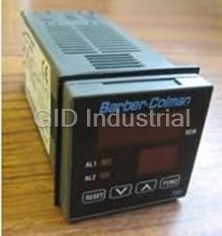
BARBER COLMAN 7EM

Description
Barber Colman 7EM Series 1/8 DIN Temperature Controllers
Part Number
7EM
Price
Request Quote
Manufacturer
BARBER COLMAN
Lead Time
Request Quote
Category
PRODUCTS - 7
Features
- 100 to 240 Vac Switching Power Supply
- Algorithms for Heat or Heat/Cool Control
- Autotuning
- Control Output Disable Function
- Dual 3 Digit LED Display
- Input (T/C, RTD)
- NEMA 4X
- Up to 2 Independent Alarms Configurable with Automatic or Manual Reset
- Up to 3 Outputs
Datasheet

Extracted Text
p 7EM Temperature Controllers ADVANTAGE EZ Series 7EM 1/8 DIN Temperature Controller • Dual 3 Digit LED Display • Input (T/C, RTD) • Autotuning • NEMA 4X • 100 to 240 Vac Switching Power Supply • Algorithms for Heat or Heat/Cool Control • Up to 3 Outputs • Up to 2 Independent Alarms Configurable with Automatic or Manual Reset • Control Output Disable Function The Advantage EZ 7EM 1/8 DIN Controllers are configurable autotuning controllers for applications where input ranges do not exceed 999. Optional Features • 24 Vac/Vdc Supply • Heater Breakdown Input • Two Temperature Alarms • Heater Breakdown Alarm and Load Current Display in Engineering Units Introduction The Barber-Colman Series 7 establishes a new class of microprocessor based temperature controllers. As part of the Series 7 family, the 7EM offers outstand- ing performance features in a cost effective package. Designed specifically for equipment manufacturers who demand tight process control, the 7EM has a va- riety of standard features commonly found as options on our competitors control- lers. NEMA 4X faceplates allow these units to be used in severe conditions. The 3 digit display offers complete coverage for extrusion and environmental cham- ber applications without excess cost for unused digits. The 7EM is easy to configure and use. Even operators without skills in tempera- ture process control or knowledge of PID control parameters can obtain perfect control. For best results in control stability, simply: • wire the instrument • configure the setpoint and alarm thresholds • initiate the autotune function Controllers p 7EM Temperature Controllers Specifications Case: ABS black. Self-extinguishing degree V-0 according to UL, VDE and CSA. Front Protection: Designed and tested for IP54 according to IEC 529 and CEI 70-1. Installation: Panel mounting by means of brackets. Rear Terminal Block: Up to 21 screw terminals, with safety rear cover. Dimensions: 48 x 96 mm (1.890 x 3.780 in.) according to DIN 43700; 89 mm (3.504 in.) deep. Weight: 400 grams maximum (1 pound). Power Supply (Switch Mode): - 100 to 240 Vac. 50/60 Hz (10% to -15% of the nominal value). - 24 Vac/Vdc. (±10% of the nominal value). Power Consumption: 11 VA. Insulation Resistance: Greater than 2 GΩ for 500 Vdc according to IEC 348. Isolation Voltage: 1500 Vrms according to IEC 348. D/A Conversion: Dual slope integration. Noise Immunity: a)Electrical fast transient/burst requirements: Severity Level 3 (according to IEC 801-4). b)Electric discharge requirements: Severity Level 8 (according to IEC 801-2). Sampling Time: 500 ms. Accuracy: ±0.2% full scale span or ±1°C, @ 25 °C and nominal power supply voltage. Common Mode Rejection Ratio: 120 dB @ 50/60 Hz. Normal Mode Rejection Ratio: 60 dB @ 50/60 Hz. Operating Temperature: From 0 to 50 °C. Storage Temperature: From -20 to 70 °C. Humidity: From 20% to 85% RH non-condensing. Protection: Internal jumper for configuration and calibration parameters. Control Action On/Off, PID or Smart AT Autotuning Special Function: Standby alarm sequence. Inputs (All inputs are factory calibrated and selectable from the keyboard.) Types: Thermocouples (J, K, L, N, T) or RTD Pt 100, keyboard configurable. Engineering Units: °C and °F keyboard configurable. Reference Junction: Automatic compensation for an ambient temperature between 0 and 50 °C. Line Impedance: 100 Ω maximum for TC input. 20 Ω/wire maximum for RTD input. Reference Junction Drift: 0.1 °C/°C. Input Impedance: Greater than 1 MΩ. Sensor Break: Downscale or upscale programmable. On RTD inputs, an OVERRANGE is indi- cated when input resistance is less than 15 Ω (short circuit sensor detection.) Calibration: According to IEC 584-1 and DIN 43710-1977. Controllers p 7EM Temperature Controllers Specifications (continued) Standard Ranges Is nput Range LC0F to800˚07 to999˚DIN43710-197 JC0F to800˚01 to999˚IEC584- KC0F to999˚01 to999˚IEC584- NC0F to999˚01 to999˚IEC584- RC TDPt100-0 19.9to99.9˚DIN4376 RCTDPt100-F 199to500˚-0199to999˚DIN4376 Current Transformer Input for OUT 1 Heater Breakdown Detection (Optional) This feature allows measurement of the load current by means of a current transformer and signals an alarm condition when the current is below a pre-programmed threshold value. Input Range: 50 mAac. Scaling: Configurable from 10 Amps to 100 Amps (with a 1 Amp step). Resolution: - for full scale up to 20 Amps: 0.1 Amp. - for full scale from 21 Amps to 100 Amps: 1 Amp. Active Period: - for relay output: NO or NC configurable. - for SSR output: logic level 1 or 0 configurable. Minimum On Time to perform the measurement: 50 ms. Outputs Main Output: (Heating) Relay or SSR (jumper selectable) - Relay SPDT, contact rating 3 Amps @ 250 Vac on resistive load. - Logic output for SSR, 700 Ω maximum load, short circuit protected. Logic Level 1: 14 Vdc ±20% @ 20 mA max. 24 Vdc ±20% @ 1 mA max. Logic Level 0: Less than 0.5 Vdc Output 2 (Cooling or Alarm 1) Relay or SSR (jumper selectable) - Relay SPST, contact rating 2 Amp @ 250 Vac on resistive load. - Logic output for SSR, 700 Ω maximum load, short circuit protected. Logic Level 1: 14 Vdc ±20% @ 20 mA max. 24 Vdc ±20% @ 1 mA max. Logic Level 0: Less than 0.5 Vdc Output 3 (Alarm 2 or Heater breakdown) - Relay SPST, contact rating 2 Amp @ 250 Vac on resistive load. (normally open contact only) Controllers p 7EM Temperature Controllers Specifications (continued) Alarms Alarm Functions: Process Alarm Deviation Alarm Band Alarm Type of Alarm: - High/Low (Outside/Inside for band alarm) - Direct/Reverse - Standby Sequence/No Standby Sequence Alarm Hysteresis: 0.1 to 10.0% of input span or 1 least significant digit. Alarm Output: Relay SPST 2 Amp @ 250 Vac resistive load. Display Characteristics Upper Display: 3 digit 7 segment green LED display; 10 mm high. Lower Display: 3 digit 7 segment orange LED display; 7.6 mm high. Indicators: 1 red LED when main (heating) output is ON. 1 red LED when cooling (or alarm 1) output is ON. 1 red LED when alarm 2 (or hbd alarm) output is ON. 1 red LED when Smart AT is enabled. Operator Interface Upper Display Indicators Shows the actual measured value or MAIN Lit during the ON period of the heating (during configuration) the value of the cycle. selected parameter. AL1 Lower Display COOL Lit when Alarm 1 is ON or during the ON Shows the operating setpoint; the heater period of the cooling cycle. PV current (in Amps); and the abbreviated name of the selected parameter. AL2 HB Lit when Alarm 2 is in ON or when the heater SV breakdown alarm is ON. Keyboard Description Decreases the selected parameter. AT Flashes during startup autotuning. Lit MAIN AL1 AL2 AT steadily during adaptive autotuning. COOL HB Increases the selected parameter. Displays in sequence all parameters FUNC and saves new settings or displays FUNC the output level and heater current. AT Starts the default param- + eter loading procedure. Enables/disables the out- + FUNC put power OFF function. Controllers p 7EM Temperature Controllers Wiring Rear Terminal Block 12 1 PWR LINE 100/240Vac 24 Vac/Vdc 13 TC - 14 3 SSR AL1/C + 4 15 16 NO 5 AL1/C C 17 6 IN-CT - 18 7 SSR MAIN + 19 8 C 20 9 MAIN NO C 21 10 AL2/HB 22 NC NO 11 Controller Wiring Power Line Wiring NOTE: Connect neutral to terminal 12. 12 Power Supply Before connecting power to the instrument, make certain the line voltage corresponds to 13 100 to 240 Vac RMS the model number. or 24 Vac/Vdc To avoid electric shock, connect the power line at the end of the wiring procedure. 24 Vdc supplies are not polarity sensitive. 6 7 Current transformer Heater RTD Controllers p 7EM Temperature Controllers Wiring (continued) Input Wiring Thermocouple Input Wiring _ NOTE: Do not run input wires together with power 3 cables. For TC wiring use proper compensat- ing cable, preferably shielded. If shielded 1 cable is used, it should be grounded at one point only. Shield Do not run RTD wires together with power _ 3 cables. If shielded cable is used, it should be grounded at one point only. Use copper wires 1 of the appropriate size (see "Specifications"). The resistance of the 3 wires must be the Shield same. RTD RTD NOTE: Any external components (like zener diodes etc.) connected between sensor and input ter- minals may cause errors in measurement due 4 3 1 4 3 1 to excessive or unbalanced line resistance, or possible leakage currents. RTD Input Wiring Voltage Output for SSR Drive _ 18 _ OUT 1 Logic voltage for SSR drive. (Main) Logic status 1: 24V +20% @ 1 mA 19 14 V +20% @ 20 mA Logic status 0: Less than 0.5 V Solid State Relay NOTE: This output is not isolated. Isolation between _ instrument output and power supply must be 14 _ assured by the external solid state relay. OUT 2 (Al 1/Cool) 15 Solid State Relay Controllers p 7EM Temperature Controllers Wiring (continued) Relay Output Wiring The relay outputs are protected by a varistor. Refer to the specifications for contact ratings of individual re- lays. C - OUT 1 C 20 C R Power NO - OUT 1 Line OUT 1 21 R (Main) NC - OUT 1 LOAD 22 External Switch in Series with the Internal Contact NO 16 OUT 2 (Al 1/Cool) C 17 Inductive Loads NO 11 OUT 3 High voltage transients may occur when switching in- (Al 2/Hbd) C ductive loads. These transients may introduce distur- 10 bances which can affect the performance of the in- strument. The internal varistor assures protection up to 0.5 Amp of inductive component of the load. The same problem may occur when a switch is used in series with the internal contacts. In this case, it is rec- ommended to install an additional RC network across the external contact as shown. The value of capacitor (C) and resistor (R) are shown in the following table. Load C R Resistor Resistor and Current (uF) (W) Power (W) Capacitor Voltage Less than 150 mA 0.1 22 2 260 Less than 0.5 Amp 0.33 47 2 260 Less than 1 Amp 0.47 47 2 260 Relay output wiring must be as far away as possible from input or communication cables. See “Controller Mounting Dimensions” at the end of this section. Controllers
Frequently asked questions
What makes Elite.Parts unique?

What kind of warranty will the 7EM have?
Which carriers does Elite.Parts work with?
Will Elite.Parts sell to me even though I live outside the USA?
I have a preferred payment method. Will Elite.Parts accept it?


What they say about us
FANTASTIC RESOURCE
One of our top priorities is maintaining our business with precision, and we are constantly looking for affiliates that can help us achieve our goal. With the aid of GID Industrial, our obsolete product management has never been more efficient. They have been a great resource to our company, and have quickly become a go-to supplier on our list!
Bucher Emhart Glass
EXCELLENT SERVICE
With our strict fundamentals and high expectations, we were surprised when we came across GID Industrial and their competitive pricing. When we approached them with our issue, they were incredibly confident in being able to provide us with a seamless solution at the best price for us. GID Industrial quickly understood our needs and provided us with excellent service, as well as fully tested product to ensure what we received would be the right fit for our company.
Fuji
HARD TO FIND A BETTER PROVIDER
Our company provides services to aid in the manufacture of technological products, such as semiconductors and flat panel displays, and often searching for distributors of obsolete product we require can waste time and money. Finding GID Industrial proved to be a great asset to our company, with cost effective solutions and superior knowledge on all of their materials, it’d be hard to find a better provider of obsolete or hard to find products.
Applied Materials
CONSISTENTLY DELIVERS QUALITY SOLUTIONS
Over the years, the equipment used in our company becomes discontinued, but they’re still of great use to us and our customers. Once these products are no longer available through the manufacturer, finding a reliable, quick supplier is a necessity, and luckily for us, GID Industrial has provided the most trustworthy, quality solutions to our obsolete component needs.
Nidec Vamco
TERRIFIC RESOURCE
This company has been a terrific help to us (I work for Trican Well Service) in sourcing the Micron Ram Memory we needed for our Siemens computers. Great service! And great pricing! I know when the product is shipping and when it will arrive, all the way through the ordering process.
Trican Well Service
GO TO SOURCE
When I can't find an obsolete part, I first call GID and they'll come up with my parts every time. Great customer service and follow up as well. Scott emails me from time to time to touch base and see if we're having trouble finding something.....which is often with our 25 yr old equipment.
ConAgra Foods