

 Manufacturers
BALDOR ECP4407TS-4

Description
Baldor ECP4407TS-4 | Severe Duty Motor | NEMA frame | TEFC enclosure | Three Phase | Totally Enclosed | Foot Mounted | HP 200 | RPM 1800 | Frame 447TS | "C" Dim. 44.48 | Aprx. Wt. (lb) 2589 | Voltage 460 | Full Load Amps 223
Part Number
ECP4407TS-4
Price
Request Quote
Manufacturer
BALDOR
Lead Time
Request Quote
Category
PRODUCTS - E
Features
- Cast iron frames V-Ring shaft seal
- Corrosion resistant epoxy finish
- Corrosion resistant hardware
- ECP motors are XEX Designs
- Moisture resistant copper windings
- Oversized rotatable cast iron conduit box
- Positive lubrication system
- Regreasable ball or roller bearings
- Stainless steel nameplate
Datasheet

Extracted Text
Above NEMA Duty Master AC Motors Frames: 5000, 5800, 6800, 7111, 9000, G315, G400, G500 Enclosures: Open and Totally Enclosed Mounting: Horizontal and Vertical Installation & Operating Manual 8/12 MN420 Any trademarks used in this manual are the property of their respective owners. Be sure to check www.baldor.com for the latest version of this manual in Adobe Acrobat PDF format. Table of Contents Section 1 General Information ............................................................................... 1-1 Overview ..................................................................................... 1-1 Safety Notice .................................................................................. 1-1 Receiving ..................................................................................... 1-3 Handling ...................................................................................... 1-3 Storage ....................................................................................... 1-4 Unpacking .................................................................................... 1-4 Section 2 Installation & Operation ........................................................................... 2-1 Overview ..................................................................................... 2-1 Location ...................................................................................... 2-1 Foundation .................................................................................... 2-1 Pre Installation Checks ......................................................................... 2-2 Doweling & Bolting ............................................................................. 2-2 Coupling ...................................................................................... 2-3 Grouting ...................................................................................... 2-4 Lubrication .................................................................................... 2-4 Anti Friction Bearings (Grease Lubricated) .................................................... 2-4 Sleeve Bearing (Oil Lubricated) .............................................................. 2-4 Electrical Connection ........................................................................... 2-4 Grounding .................................................................................... 2-5 Pre−Operation Check .......................................................................... 2-6 First Time Uncoupled Start−Up .................................................................. 2-6 Coupled Start−up .............................................................................. 2-7 Jogging and Repeated Starts .................................................................... 2-7 Section 3 Maintenance & Troubleshooting .................................................................... 3-1 Periodic Inspection ............................................................................. 3-1 Bearing Lubrication ............................................................................ 3-2 Anti−Friction Bearing (Grease Lubricated) ......................................................... 3-2 Anti−Friction Bearing (Oil Mist Lubricated) ......................................................... 3-3 Sleeve Bearings (Oil Lubricated) ................................................................. 3-5 Sleeve Bearing Replacement .................................................................... 3-5 G50 Sleeve Bearing Removal ............................................................... 3-6 G50 Sleeve Bearing Replacement ........................................................... 3-7 G5000, G315, G5810 and G40 Sleeve Bearing Removal ....................................... 3-7 G5000, G315, G5810 and G40 Sleeve Bearing Replacement ................................... 3-8 Sleeve/Anti−Friction Bearing Bracket Removal ..................................................... 3-9 Anti−Friction Bearing Removal/Replacement ...................................................... 3-9 Rotor And Stator Removal ...................................................................... 3-9 Winding Maintenance .......................................................................... 3-9 Auxiliary Cooling ............................................................................... 3-10 Renewal Parts ................................................................................. 3-10 MN420 Table of Contents i Section 4 Accessories ...................................................................................... 4-1 Winding Resistance Temperature Detector RTD ................................................... 4-1 Winding Thermostat ............................................................................ 4-1 Winding Thermocouple − T/ C ................................................................... 4-2 Winding Thermistors ........................................................................... 4-2 Bearing Resistant Temperature Detector − RTD .................................................... 4-2 Suggested Bearing and Winding RTD Setting Guidelines ............................................ 4-3 Bearing Thermocouple − T/C .................................................................... 4-3 Bearing Thermostat ............................................................................ 4-4 Bearing Thermometer .......................................................................... 4-4 Space Heaters ................................................................................ 4-4 Oil Circulation System .......................................................................... 4-4 Constant Level Oiler ............................................................................ 4-5 Differential Air Pressure Switch .................................................................. 4-5 Differential Air Pressure Indicator ................................................................ 4-6 Current Transformers ........................................................................... 4-6 Lightning Arrestors And Surge Capacitors ......................................................... 4-6 Air Filters ..................................................................................... 4-6 Section 5 Vertical Solid Shaft Motors ......................................................................... 5-1 Overview ..................................................................................... 5-1 Maintenance .................................................................................. 5-1 Grease Lubricated Bearings ................................................................ 5-1 Oil Lubricated Bearings ..................................................................... 5-2 Adjustment of Axial Float ........................................................................ 5-4 Grease Lubricated Thrust Bearing ........................................................... 5-4 Oil Lubricated Thrust Bearing ............................................................... 5-4 Non Reverse Ratchet ........................................................................... 5-5 Thrust Bearing Oil Cooler ....................................................................... 5-5 Section 6 Cross Sectional Drawings ......................................................................... 6-1 ii Table of Contents MN420 Section 1 General Information Overview Baldor�Reliance Duty Master motors provide industry leading value largely because of their 100+ year heritage of exceeding customer expectations, This includes providing Above NEMA Motors to customers for more than 50 years and in doing so, gaining a deep understanding of a broad range of industries and critical applications, The Baldor−Reliance product legacy extends from a wide range of general purpose motors to motors designed for the most hazardous and critical application extremes. In addition to Baldor’s being the most preferred supplier of industrial motors in North America, Baldor�Reliance is also the most specified motor in the Petrochemical industry and is the first motor to be certified under the API 547 monogram program. Nobody knows more about their process than the customer. That is why Baldor employs dedicated Industry teams whose sole purpose is working directly with Industry users, consultants and OEMs. These experienced Baldor engineers are dedicated to understanding the customer’s specific performance requirements and translating this into solutions and products that exceed customer expectations. This manual contains general procedures that apply to Baldor “Above NEMA” Motor products. Be sure to read and understand the Safety Notice statements in this manual. For your protection, do not install, operate or attempt to perform maintenance procedures until you understand the Warning and Caution statements. A Warning statement indicates a possible unsafe condition that can cause harm to personnel. A Caution statement indicates a condition that can cause damage to equipment. The following pages contain the information that you need to get the most out of your Duty Master Motor. Please read it carefully and thoroughly before unpacking and installing motor. Safety Notice: This equipment contains high voltage! Electrical shock can cause serious or fatal injury. Only qualified personnel should attempt installation, operation and maintenance of electrical equipment. Be sure that you are completely familiar with NEMA publication MG-2, safety standards for construction and guide for selection, installation and use of electric motors and generators, the National Electrical Code and local codes and practices. Unsafe installation or use can cause conditions that lead to serious or fatal injury. Only qualified personnel should attempt the installation, operation and maintenance of this equipment. MN420 General Information 1-1 WARNING: Do not touch electrical connections before you first ensure that power has been disconnected. Electrical shock can cause serious or fatal injury. Only qualified personnel should attempt the installation, operation and maintenance of this equipment. WARNING: Be sure the system is properly grounded before applying power. Do not apply AC power before you ensure that all grounding instructions have been followed. Electrical shock can cause serious or fatal injury. National Electrical Code and Local codes must be carefully followed. WARNING: Avoid extended exposure to machinery with high noise levels. Be sure to wear ear protective devices to reduce harmful effects to your hearing. WARNING: This equipment may be connected to other machinery that has rotating parts or parts that are driven by this equipment. Improper use can cause serious or fatal injury. Only qualified personnel should attempt to install operate or maintain this equipment. WARNING: Do not by-pass or disable protective devices or safety guards. Safety features are designed to prevent damage to personnel or equipment. These devices can only provide protection if they remain operative. WARNING: Avoid the use of automatic reset devices if the automatic restarting of equipment can be hazardous to personnel or equipment. WARNING: Be sure the load is properly coupled to the motor shaft before applying power. The shaft key must be fully captive by the load device. Improper coupling can cause harm to personnel or equipment if the load decouples from the shaft during operation. WARNING: Use proper care and procedures that are safe during handling, lifting, installing, operating and maintaining operations. Improper methods may result in bodily injury. WARNING: Before performing any motor maintenance procedure, be sure that the equipment connected to the motor shaft cannot cause shaft rotation. If the load can cause shaft rotation, disconnect the load from the motor shaft before maintenance is performed. Unexpected mechanical rotation of the motor parts can cause injury or motor damage. WARNING: Disconnect all electrical power from the motor windings and accessory devices before disassembly of the motor. Electrical shock can cause serious or fatal injury. WARNING: Do not use non UL/CSA listed explosion proof motors in the presence of flammable or combustible vapors or dust. These motors are not designed for atmospheric conditions that require explosion proof operation. WARNING: Motors that are to be used in flammable and/or explosive atmospheres must display appropriate hazardous location markings including zone/division, class group and temperature codes. Specific service conditions for these motors are defined in NFPA 70 (NEC) Article 500. WARNING: UL Listed motors must only be serviced by UL Approved Authorized Baldor Service Centers if these motors are to be returned to a hazardous and/or explosive atmosphere. WARNING: This equipment is at line voltage when AC power is connected. Disconnect and lockout all ungrounded conductors of the ac power line before proceeding. Failure to observe these precautions could result in severe bodily injury or loss of life. WARNING: Rotating parts can cause serious or fatal injury. If relubrication is performed with the motor running, to avoid injury do not contact any rotating parts. WARNING: Solvents can be toxic and/or flammable. Follow manufacturer’s safety procedures and directions. Failure to observe this precaution could result in bodily injury. WARNING: Use of an air jet may cause flying debris and generate particulate matter. Wear suitable skin, eye and respiratory protection. Failure to observe this precaution may result in bodily injury. WARNING: Space Heaters operate at line voltage. Disconnect power to space heaters before performing maintenance work on motor. Failure to observe this precaution could result in severe bodily injury or loss of life. WARNING: Thermostat contacts automatically reset when the motor has slightly cooled down. To prevent injury or damage, the control circuit should be designed so that automatic starting of the motor is not possible when the thermostat resets. WARNING: High Voltage may be present even when the machine is not rotating. Ensure that power has been disconnected before touching the motor or any of its components. Electrical shock can cause serious or fatal injury. Continued on next page. 1-2 General Information MN420 Section 1 General Information Safety Notice Continued Caution: Do not lift the motor and its driven load by the motor lifting hardware. The motor lifting hardware is adequate for lifting only the motor. Disconnect the load from the motor shaft before moving the motor. Caution: If eye bolts are used for lifting a motor, be sure they are securely tightened. The lifting direction should not exceed a 20 angle from the shank of the eye bolt or lifting lug. Excessive lifting angles can cause damage. Caution: For motors built with an external circulating oil system (flood lube), refer to the motor nameplate for the appropriate orifice, pressure and flow rates for the oil. Caution: To avoid damage to the windings do not use air pressures greater than 30 psi (200 kPa). Avoid directing the air in such a way that the dirt will be blown into inner crevices. Caution: To prevent premature equipment failure or damage, only qualified maintenance personnel should perform maintenance. Caution: Do not over−lubricate motor as this may cause premature bearing failure. Caution: Over−lubricating can cause excessive bearing temperatures, premature lubrication breakdown and bearing failure. Caution: To prevent equipment damage, be sure that the electrical service is not capable of delivering more than the maximum motor rated amps listed on the rating plate. Caution: If a HI POT test (High Potential Insulation test) must be performed, follow the precautions and procedure in NEMA MG1 and MG2 standards to avoid equipment damage. Caution: To avoid damage to motor bearings, grease must be kept free of dirt. For an extremely dirty environment, contact your Baldor distributor or an authorized Baldor District Office for additional information. Caution: Do not use solvents containing trichloroethane to clean interior or exterior of motor. Damage may occur to paint and insulation systems. Caution: When driven equipment may be damaged by incorrect rotation direction, uncouple the motor form load and check motor rotation direction during initial start and be sure rotation is correct. Caution: Motors with oil lubricated bearings (such as sleeve bearings) are shipped without oil. As soon as the motor is received, the bearing oil reservoir should be filled to the indicated level with the proper lubrication oil (see Section 4 “Constant Level Oiler”). To avoid motor damage, do not rotate the shaft until you have filled the oil reservoirs to the proper level with recommended lubricant. Caution: Repeated starts and/or jogs can greatly reduce the life of an induction motor. Caution: The space heaters are designed to operate at or below the maximum surface temperature stated on the nameplate. If the marked ambient and/or voltage are exceeded this maximum surface temperature can be exceeded and can damage the motor windings. If applied in a division 2 or zone 2 environment this excessive temperature may cause ignition of hazardous materials. If you have any questions or are uncertain about any statement or procedure, or if you require additional information please contact your Baldor District Office. Receiving Each motor is thoroughly tested at the factory and carefully packaged for shipment. When you receive your motor, there are several things you should do immediately. Do not unpack until ready for use. 1. Observe the condition of the shipping container and report any damage immediately to the commercial carrier that delivered your motor. 2. Verify that the part number of the motor you received is the same as the part number listed on your purchase order. Handling The motor should be lifted using the lifting lugs or eye bolts provided. 1. Eyebolts or lifting lugs are intended for lifting only the motor with the standard factory installed accessories such as tachometer, etc., the lifting means on the motor must not be used to lift the motor plus additional equipment such as gears, pumps, compressors, or other driven equipment. The lifting means on the motor cannot be used to lift assemblies of motor and other equipment mounted on a common base. 2. In all cases, care should be taken to assure lifting in the direction intended in the design of the lifting means. Lift using all lugs provided using a hoist with adequate capacity. Be sure lift or hoist equipment has appropriate tires for the terrain to avoid becoming stuck or tipping over. If the shipping pallet is intact, use a fork lift to move the motor. If the shipping pallet is not used, lift using all lugs provided. Likewise, precautions should be taken to prevent hazardous overloads due to deceleration, acceleration or shock forces. Angle of lift with rope or chain never to be less than 45 from horizontal. MN420 General Information 1-3 Figure 1-1 Lifting Motor Storage Do not unpack until ready for use. If the motor is not put into service immediately, the motor must be stored in a clean, dry and warm location. Several precautionary steps must be performed to avoid motor damage during storage. Caution: Oil lubricated motors are shipped without oil. As soon as the motor is received, the bearing oil reservoir should be filled to the indicated level with the proper lubrication oil (see Section 4 “Constant Level Oiler”). To avoid motor damage, do not rotate the shaft until you have filled the oil reservoirs to the proper level with recommended lubricant. 1. The motor should be inspected periodically and the insulation resistance checked and recorded monthly (see Checking Insulation Resistance in section 3). If there is a significant change in insulation resistance, it should be investigated and corrective action should be taken. Consult your local Baldor District office for additional data. 2. Do not lubricate bearings during storage. Duty Master anti−friction bearing motors are shipped with the proper amount of grease in each bearing. 3. At 30 day intervals, remove only enough packing to expose the shaft and remove the shaft shipping brace, rotate the shaft (by hand) 10 to 15 revolutions. This distributes the grease, preventing bearing corrosion due to condensation, or to the presence of contaminating gases near the motor. After rotating the shaft replace protective packing and shaft shipping brace. 4. If the storage location is cold, damp or humid, the motor windings must be protected from moisture. This can be done by applying power to the motors’ space heater (if available) while the motor is in storage. If space heaters are not installed, the motor can be kept warm by placing several 100 or 150 watt electric lamps inside the enclosure and connect them to a power source. 5. For grease lubricated bearings, if the motor is stored and directly exposed to weather conditions, it is important that the bearing cavity be inspected for the presence of water at the grease drain. If the cavity is contaminated with water, the motor must be disassembled, grease removed from the bearing(s) and housing(s) and bearing(s) inspected for corrosion. If corrosion is present, the bearing(s) must be replaced. If there is no corrosion, repack the bearing(s) / housing(s) with grease as instructed in Section 3. 6. Duty Master motors with oil lubricated sleeve bearings are tested using an oil containing a rust inhibitor. This additive protects the bearings and associated structural parts from rust and corrosion. Prior to shipment the oil is drained. A thin film of oil remains on the vital parts providing short term temporary rust protection. As soon as the motor has been received, the bearing oil reservoir should be filled to the required oil level and with the proper oil lubrication. (See Section 3 Bearing Lubrication for proper type). Unpacking Each Baldor motor is packaged for ease of handling and to prevent entry of contaminants. 1. To avoid condensation inside the motor, do not unpack until the motor has reached room temperature. (Room temperature is the temperature of the room in which it will be installed). The packing provides insulation from temperature changes during transportation. 2. When the motor has reached room temperature, carefully remove the motor from packaging. Lifting provisions are provided as eyebolts or cast lifting lugs located on top of the motor. Place a lifting hook in each of the lifting means provided and carefully lift the motor from its packing, see Figure 1-1. Use a hoist with adequate capacity. Use spreader bars as required to ensure that lift chains/cables do not pull at an angle and prevent damage to lifting eyes or motor hoods. 1-4 General Information MN420 Section 2 Installation & Operation Overview Installation should conform to the National Electrical Code as well as local codes and practices. When other devices are coupled to the motor shaft, be sure to install protective devices to prevent future accidents. Some protective devices include, coupling, belt guard, chain guard, shaft covers etc. These protect against accidental contact with moving parts. Machinery that is accessible to personnel should provide further protection in the form of guard rails, screening, warning signs etc. 1. If the motor has been in storage for an extended period or had been subjected to adverse moisture conditions, check the insulation resistance of the stator winding (see Checking Insulation Resistance in section 3). 2. Examine the motor nameplate data to make sure it agrees with the power circuit to which it will be connected. The motor is guaranteed to operate successfully at line frequency not more than 5%, and line voltage not more than 10%, above or below the nameplate ratings, or a combined variation of voltage and frequency of not more than 10% above or below nameplate ratings. Efficiency, power factor and current may vary from nameplate data. 3. Check to make sure that direction of motor rotation is corrected for the intended application. Location It is important that motors be installed in locations that are compatible with motor enclosure and ambient conditions. Improper selection of the motor enclosure and ambient conditions can lead to reduced operating life of the motor. The motor must be located in an environment that satisfies local codes. For locations outside the USA., compliance with IEC requirements and other regulatory agencies are required. The following additional considerations should also govern its location: For open and protected motors the installation should be in a location that provides adequate space for air circulation of the external cooling fan. Exposure to high ambient temperatures, humidity and atmospheric contamination should be avoided. Acids, alkalis and gases also have detrimental effects on electrical machinery. The location of installation should be accessible for routine maintenance and inspection. If the room is not large enough to have natural ventilation, some external source of forced and filtered air will be necessary. The room should be such that the heat developed during operation can escape and will not be recirculated over the equipment. Permanent handling equipment to facilitate major service and repair without complete disassembly of the individual units should be considered. If the motor must be moved or additional handling or shipment of motor be required, be certain to block the shaft as it was blocked for shipment by the factory. Blocking the shaft, limits the rotor movement both axially and radially which prevents damage to the bearings. Hazardous Locations are those where there is a risk of ignition or explosion due to the presence of combustible gases, vapors, dust, fibers, or flyings. Facilities requiring special equipment for hazardous locations are typically classified in accordance with local requirements. In the US market, guidance is provided by the National Electric Code. EMC Compliance Statement for European Union The motors described in this instruction manual are designed to comply 2004/108/EC . These motors are commercial in design and not intended for residential use. Foundation The dimensions for mounting are shown on the outline drawing supplied with the motor software and should be referred to prior to planning of the foundation. Large motors require a concrete foundation. The foundation should consist preferably of solid concrete walls or piers and should be carried down far enough to rest on a solid sub base. This base should be sufficient stiffness to prevent vibration and to insure long, trouble free operation. If necessary, a consulting engineer, who is familiar with foundation design, should design and supervise its construction. If the foundation is to be steel girders instead of concrete, the girders should be well braced and supported by adequate columns to prevent vibration due to resonance. The natural frequencies of the motor and supporting structure must be at least 20% away from the speed of rotation and twice the speed of rotation and multiples of the power line frequency. The size of the foundation is determined by the weight, size and speed of the equipment and by the type and condition of the underlying soil. The width and length of the foundation are usually made to extend at least 6 inches (150mm) beyond the equipment on all sides of the base. Increased width and weight are necessary for operation at higher speeds and for foundations that project above the floor level to give stability against rocking and resonant vibration. Large motors are not rigid or self supporting, and should be uniformly supported. Therefore, when set on the foundation or base, adequate support should be provided by leveling plates and shims between the frame and the foundation, at points of loading; Le., under the frame feet, and intersection points of the beams as well as under long, unsupported sections of the base. The number of shims should be kept to a minimum. A few thick ones are preferred over many thin ones. MN420 Installation & Operation 2-1 A 1 inch (25mm) space should be allowed between the base and foundation for grouting. The concrete surface should be roughed to provide a good bonding surface. The lateral clearance for positioning the base can be made by providing a space around the hold down bolts, that are secured head down to an anchoring washer, Figure 2-1. A sleeve may be used to form the hole when poring the foundation around the bolt for the length between the anchoring washer and the top surface of the concrete foundation. The size and depth of the hole will depend upon the size of the motor and accuracy of the hole location. A template can be used to locate the hold down bolts. The bolts can be locked in place later, by filling the clearance hole with grout. Figure 2-1 Suggested Foundation Bolt Installation Bolt Foundation Pipe Washer Pre Installation Checks The assurance of successful start−up depends upon the use of good handling, inspection, and installation practices. Before shipment, every motor is given a running test to check operation. Although complete factory tests have been made, motors should be checked for any change resulting from improper handling during shipment, storage, installation or by an unsatisfactory foundation. Failure to check or do the necessary work as mentioned above, could cause misalignment resulting in vibration and premature bearing failure. Before the motor is checked for alignment, remove all shipping blocks and supports installed at the factory. The shaft should turn over freely. The degree of accuracy required in the alignment depends on the rated speed of the machine. The greater the speed, the greater the care and accuracy necessary in the alignment. The motor must be level to maintain the proper oil level. Check the driven equipment to make sure that the motor will be coupled to a level shaft. If necessary, level it up before coupling. Doweling & Bolting After proper alignment is verified, dowel pins should be inserted through the motor feet into the foundation. This will maintain the correct motor position should motor removal be required. (Baldor motors are designed for doweling.) 1. Drill dowel holes in diagonally opposite motor feet in the locations provided. 2. Drill corresponding holes in the foundation. 3. Ream all holes. 4. Install proper fitting dowels. 5. Mounting bolts must be carefully tightened to prevent changes in alignment. Use a flat washer and lock washer under each nut or bolt head to hold the motor feet secure. Flanged nuts or bolts may be used as an alternative to washers. Soft foot is a condition in which one or more of the motor feet do not rest squarely on the base. This condition causes distortion of the motor frame once the mounting bolts are tightened and can lead to elevated vibration levels. Prior to alignment, the following procedure should be followed to minimize the effects of soft foot. a. With the motor mounted on the base use a dial indicator to measure the soft foot deflection at each mounting location. b. With all feet firmly torqued to 120 ft−lbs loosen and tighten each foot measuring the total foot deflection. The total foot deflection should not exceed 2.00 mils. c. If the foot deflection exceeds 2.00 mils shim foot as necessary to reduce deflection”. 6. Tighten all motor mounting bolts to the identical recommended initial torque value. 7. Place a dial indicator to read vertical displacement on the top of a motor foot. 8. Loosen the mounting bolt in that foot and record the amount of deflection shown by the dial indicator. 9. Foot deflection should be limited to 0.001”−0.002”. If deflection exceeds this level, proceed to step 10. If it does not, proceed to step 11. 10. Place an amount of shims that corresponds to the measured deflection under the foot. 11. Retighten the bolt and repeat the procedure on the remaining motor feet. 2-2 Installation & Operation MN420 Coupling 1. In preparation for making the coupling alignment, wash off the rust protective slushing compound on the motor shaft and factory installed couplings with solvent. On sleeve bearing motors. remove the rust preventative from the shaft to expose the magnetic center and rotor float scribe lines. Fill oil sumps with proper oil to the proper level. 2. The couplings should be heated for proper mounting. Do not press or drive it onto the shaft. The shaft extension key length should be sized per Figure 2-2. Figure 2-2 A L= Key Length A= Coupling Hub Length B= Keyway Length L A� B L � B 2 3. Motors supplied with sleeve bearings. The drive end shaft Extension is scribed with three lines indicating the magnetic center line and rotor end float limits. A single scribe line, magnetic center only is used in cases where the float extreme scribe lines would interfere with a shaft shoulder or extension keyway. The magnetic center scribe line is filled with light colored paint and covered with masking tape prior to coating with rust protection. The distance from the magnetic center scribe line to the reference surface is indicated on a name plate attached to the motor frame. The magnetic center is within +0.06 in. (+1.5 mm) of the rotor float mechanical center. Rotor end float is 0.50 inch (12.7 mm) minimum. Sleeve bearing motors are not designed to withstand external axial thrust. A limited axial float coupling should be used. Total end float of the coupling should not exceed 0.19 inch (4.8 mm) (.09 inch. +2.3 mm). The motor axial placement should be established by locating the shaft on its magnetic center and spaced from the driven equipment as recommended by the coupling manufacturer. 4. After the motor is properly positioned for axial end play and with the hold down bolts snug but not tightened prepare for the coupling alignment. Mount the coupling hubs, but do not engage the coupling. Coupling Alignment There are a number of procedures to properly align the motor to the driven equipment. The end result depends upon the accuracy of the parts in roundness, flatness, runout of the reference surfaces, rigidity of the mounting and the skill of the setup man. The motor base surfaces must be flat and parallel to the shafts. Make allowance for inserting shims under the motor to make the elevation adjustment. The shims size should be the full length of the motor foot pad, they should be flat, and free from burrs. Insert the shims carefully to maintain the foot plane and to avoid bending or twisting the motor frame. For a poor mounting surface, it may be necessary to machine a shim to compensate for the slope or surface irregularity. To minimize soft stacking, use the thickest shim stock combination with the fewest shims. A preliminary line up can be made with feeler gauge by measuring at top, bottom and sides between faces of the hubs. Angular alignment is satisfactory when there is no more than .002 in. (0.05 mm) difference between all sides of the hubs. Parallel alignment check can be made with a straight edge, or dial indicator, to determine if both hubs are parallel within 0.002 in. (0.05 mm). During shimming use shims that are as thick as possible to avoid a sponginess of an excessive number of layers. Coupling Alignment Procedure For more accurate alignment, refer to the manual for the driven equipment. When alignment is complete, tighten the motor and driven equipment hold down bolts and recheck alignment. The feet must be tightened uniformly. Ensure the feet are on the same plane by measuring the feet spring back when a bolt is loosened. It should not exceed 0.002 inch (0.050 mm) at any foot as the others remain tight. Repeat with two adjacent bolts loose. The shaft spring back should not exceed 0.001 inch (0.025 mm). In some cases it may be necessary to make a hot alignment check to compensate for thermal expansion. A compensating offset alignment should be made cold. The unit may run rough until the equipment temperatures stabilize. If for any reason alignment does not fall within limits, contact your local Baldor District Office. MN420 Installation & Operation 2-3 Grouting Grout should be used, but should not be applied until all alignment and leveling have been completed, and the set is running satisfactorily – from the bearing noise, temperature and vibration standpoint – after the 4 hour run in test. A good quality commercial non shrinking type of grouting compound should be used. A cement/sand ratio of 1:1 is recommended. Grout should be used with a minimum quantity of water to give a stiff mix. The roughened concrete surface should be washed to remove the dust and loose particles. Grouting should be applied to a wet surface but to assure a good bond, there must be no puddles of water or contamination from oil or grease. Prepare only the amount that can be handled within set time and without adding water to the original mix. The grouting should be done quickly and continuously. Tamp in place and vent the pockets to assure a solid casting, it is suggested that the motor remain idle while the grout is hardening. At least 48 hours curing timed is desirable for that grout to develop adequate strength before operating this set, or any nearby large equipment which could create a vibration. Lubrication The lubrication system should be checked in preparation for rotating the shaft during the alignment operation. Anti Friction Bearings (Grease Lubricated) Bearing chambers are packed with grease during assembly, and do not normally need additional grease at time of installation, unless the unit has been in storage and installation for 6 months or longer. Lubricant must be added per Section 3, Maintenance. Sleeve Bearing (Oil Lubricated) Caution: Oil lubricated motors are shipped without oil. As soon as the motor is received, the bearing oil reservoir should be filled to the indicated level with the proper lubrication oil (see Section 4 “Oil Rite Oiler”). To avoid motor damage, do not rotate the shaft until you have filled the oil reservoirs to the proper level with recommended lubricant. Lubricating oils for sleeve bearing motors should be selected as follows: 1. Viscosity in SUS (centistokes) at 100F. (37.8C): Table 2−1 Ambient Temperature Range** Speed 1200 RPM or Less Over 1200 RPM 0 to 120F* (–18C to 50C*) 300 (68 cSt) 150 SUS (32 cSt) –20 to 50F (–30C to 10C) 150 (32 cSt) 90 SUS (18cSt) * For higher temperatures, oil coolers should be used. ** For lower temperatures, heaters should be used to assure adequately high starting temperature. 2. Pour Point: Below minimum starting temperature. Caution: For motors equipped with circulating oil pump and adjustable needle valve, valve must be adjusted or flooding of oil sump may occur. Disconnect valve and adjust flow rate for 0.10 GPM flow (or as specified on data sheet). 3. Quality: Use a good grade of turbine type oil with rust, foam and oxidation inhibitors. Avoid automotive oils or additives other than those specifically recommended by the oil manufacturer. To fill sleeve bearing motor oil reservoirs on motors not equipped with constant level oilers, be sure that drain plugs are in place and secure and fill through filler cap until oil level shows at top line marked on oil gauge. Oil level must never be below bottom line marked on oil gauge. For motors with constant level oilers, refer to the instructions. See Accessories Section 4. Electrical Connection WARNING: Be sure the system is properly grounded before applying power. Do not apply AC power before you ensure that all grounding instructions have been followed. Electrical shock can cause serious or fatal injury. National Electrical Code and Local codes must be carefully followed. The user must select a motor starter and overcurrent protection suitable for this motor and its application. Consult motor starter application data as well as the National Electric Code and/or other applicable local codes. A conduit box may be provided for the power lines to the stator and other conduit boxes for all other electrical connections. Tapped holes are provided for grounding. 2-4 Installation & Operation MN420 Grounding Failure to properly ground the motor may cause electrical shock hazard to personnel. Do not attach ground lead to motor foot bolt. In the USA consult the National Electrical Code, Article 430 for information on grounding of motors and generators, and Article 250 for general information on grounding. In making the ground connection, the installer should make certain that there is a solid and permanent metallic connection between the ground point, the motor or generator terminal housing, and the motor or generator frame. In non−USA locations consult the appropriate national or local code applicable. All large motors should be grounded with the grounding conductor equipped with a brazed copper terminal, or with a suitable solderless terminal fastened to the motor. Soldered terminals should not be used. A washer should be used between bolt head and terminal lug. The other end should be fastened with suitable clamps or terminals to rigid metallic conduit or to the nearest available ground. Ground conductor size should be in accordance with the following National Electrical Code Table 250−122. Installation restrictions are listed in Section 250−120. Table 2−2 Size of Equipment Ground Conductor Size Rating or Setting of Automatic Overcurrent Device in Circuit Ahead of Equipment, Conduit, etc., Not Exceeding (Amperes) Copper Wire No. Aluminum or Copper Clad Aluminum Wire No.* 15 14 12 20 12 10 30 10 8 40 10 8 60 10 8 100 8 6 200 6 4 300 4 2 400 3 1 500 2 1/0 600 1 2/0 800 0 3/0 1000 2/0 4/0 1200 3/0 250MCM 1600 4/0 350MCM 2000 250MCM 400MCM 2500 350MCM 600MCM 3000 400MCM 600MCM 4000 500MCM 800MCM 5000 700MCM 1200MCM 6000 800MCM 1200MCM For motors installed in compliance with IEC requirements, the following minimum cross sectional area of the protective conductors should be used: Crosssectional area of phase Minimum crosssectional area of the corresponding conductors, S protective conductor, S p 2 2 mm mm S< 16 S 16 < S � 35 16 S>35 0,5 S Equipotential bonding connection shall made using a conductor with a cross-sectional area of 2 at least 4 mm . MN420 Installation & Operation 2-5 Note: Main power leads for CE Marked Motors may be marked U,V,W – for standard configurations, please consult connection diagrams. Connection Diagrams 2-6 Installation & Operation MN420 Connection Diagrams Continued Caution: The space heaters are designed to operate at or below the maximum surface temperature stated on the nameplate. If the marked ambient and/or voltage are exceeded this maximum surface temperature can be exceeded and can damage the motor windings. If applied in a division 2 or zone 2 environment this excessive temperature may cause ignition of hazardous materials. MN420 Installation & Operation 2-7 WARNING: This equipment is at line voltage when AC power is connected. Disconnect and lockout all ungrounded conductors of the ac power line before proceeding. Failure to observe these precautions could result in severe bodily injury or loss of life. Pre−Operation Check Be sure that all power to motor and accessories is off. Be sure the motor shaft is disconnected from the load and will not cause mechanical rotation of the motor shaft. 1. Verify that Hold Down bolts are tightened to the proper torque. 2. If the motor has been idle for a long period of time after installation, check insulation resistance. 3. Check the incoming power to be sure that line voltage, frequency and phase are correct for the motor (refer to the motor nameplate). 4. Inspect all electrical connections for proper termination, clearance, mechanical strength and electrical continuity. 5. Be sure all shipping materials and braces (if used) are removed from motor shaft. 6. Ensure alignment is correct and motor is properly lubricated. a. On machines supplied with oil lubricated bearings inspect lubrication system to insure that oil reservoirs have been filled to the proper level with correct oil. Do not overfill oil reservoirs. b. Motors operating with a forced lubrication system must have the forced lubrication system operating before starting the motor. 7. Manually rotate the motor shaft to ensure that it rotates freely. Caution: When driven equipment may be damaged by incorrect rotation direction, uncouple the motor from the load and check motor rotation direction during initial start and be sure rotation is correct. 8. When the driven machine is likely to be damaged by the wrong direction of rotation, it is best to uncouple the motor from its load during the check for rotation and/or during the initial start. Some motors are designed for a single direction of rotation as indicated by nameplates. Running those units in the wrong direction will reduce airflow causing overheating. Check to see that both the motor and driven equipment are operating in the correct direction of rotation. If it is necessary to change rotation, disconnect and lockout all input power and interchange any two input power phases. 9. Replace all panels and covers. 10. Check to see that coupling guards and other protective enclosures are not blocking the ventilating air into the motor and exhaust openings. First Time Uncoupled Start−Up Read each of the steps in the following procedure over thoroughly, so that each is fully understood, before attempting to start the motor. 1. Make the initial start by following the regular sequence of starting operations in the control instructions. 2. After starting, check that the motor is running smoothly. If the motor has excessive vibration, shut down immediately and investigate. Check for coupling and key unbalance, rusty bearing, lack of lubrication, foot planarity, structural resonance. 3. Check bearing temperatures frequently. Bearing temperature should not exceed 185F (85C). Likewise the rate of temperature rise should not be excessive. At initial start, the bearing temperature rate−of−rise is more indicative of trouble than overall temperature for a minimum of two hours, if at any time the rate of rise curve appears too steep, stop the motor immediately and re−check its alignment. 4. Ensure that the protective controls are functioning properly before any prolonged operation. 5. Run the motor for at least two hours. 2-8 Installation & Operation MN420 Coupled Start−up This procedure assumes a coupled start up. Also, that the first time start up procedure was successful. Read and fully understand each of the steps in the following procedure before attempting to start the motor. 1. Disconnect and lockout the power source. Ensure no power is applied to the motor. 2. After a successful uncoupled start, assemble the coupling and lubricate with the manufacturer’s recommended lubricant. Check to see that the coupling is not binding. 3. Verify the motor shaft is on its magnetic center. 4. Verify coupling axial movement is within the bearing float limit. 5. Check to see that coupling guards and other protective enclosures are not blocking the ventilating air over the motor and exhaust openings. 6. Try no load coupled start−up, repeating steps 1 to 5 of the “First Time Uncoupled Start−up” procedure. 7. Verify the driven equipment is not transmitting vibration back to the motor through the coupling or base. 8. Inspect the motor carefully. Make the initial start by following the regular sequence of starting operations in the control instructions. 9. After starting, check that the motor is running smoothly. If the motor shows excessive vibration, shut down immediately and investigate. Check for coupling and key unbalance, lack of lubrication, foot planarity and structural resonance. 10. Check vibration at the bearing housing. Motor vibration must not exceed the limits given in Table 2−3. Vibration severity and conversion of the above limits to velocity or acceleration can be determined by using the vibration nomograph in Figure 2-3. Nomograph shows accepted industry vibration levels. 11. Verify all panels and covers are securely in place. 12. Verify that coupling guards are properly installed and protective enclosures are not blocking the ventilating air into the motor and exhaust openings. 13. In addition, observe the following before attempted start−up of Belted, C−Face/D Flange and Sleeve bearing motors: a. For belted duty, ensure motor is intended for belted service and that the belted application data has been verified. Also be aware that some belted duty motors are built with bearings that are not suited for non−belted applications. b. Due to their size, above NEMA C−Face and D−Flange motors are supplied with mounting feet and are not designed to be supported by the C−Face or D−Flange alone. c. Sleeve bearing motors are intended for horizontal mounting only. Contact your local Baldor District Office for any questions concerning this installation before power is applied to the motor. Jogging and Repeated Starts Caution: Repeated starts and/or jogs can greatly reduce the life of an induction motor. Repeated starts and/or jogs can greatly reduce the life of an induction motor. If it is necessary to repeatedly start or jog a motor, check the application with your local Baldor District office. At ambient temperature, the motor is normally capable of making two starts in succession and coasting to rest between starts. The motor is also capable of making one start at its rated load operation temperature. For cooling time required before additional starts can be made consult your local Baldor District office or the motor starting nameplate if one is provided. If more starts than defined above are attempted in shorter period of time, severe damage to the motor electrical windings and rotor may result. The starting conditions listed above apply only if the inertia of the connected load, the load torque during acceleration, the applied voltage, and the starting method are those for which the motor was designed. For starting situations not covered here, consult your local Baldor District office before proceeding. Refer also to the motor nameplate which may list starting conditions. MN420 Installation & Operation 2-9 Table 2−3 Maximum Vibration Limits On Bearing Housing On Shaft RPM (Displacement mils Pk−Pk) (Velocity in/sec., Pk) (Displacement mils Pk−Pk) 3000−4000 Incl. 0.001 0.19 1.75 1500−2999 Incl. 0.0015 0.14 1000−1499 Incl. 0.002 0.13 2.0 999 or less 0.0025 0.12 Figure 2-3 Vibration Nomograph Displacement - Inches 10.00 9 8 7 6 5 4 3 2 1.00 0.9 0.8 0.7 0.6 0.5 Rough, 0.4 Needs Attention 0.3 0.2 Fair Acceptable 0.10 0.09 0.08 0.07 0.06 0.05 0.04 0.03 0.02 0.01 2 3 4 5 6 789 2 3 4 5 6 789 2 3 4 5 6 789 100 1,000 10,000 100,000 RPM (Divide by 60 for Hz) 2-10 Installation & Operation MN420 Velocity - Inches/Sec Hazardous Locations Hazardous locations are those where there is a risk of ignition or explosion due to the presence of combustible gases, vapors, dust, fibers or flyings. Selection Facilities requiring special equipment for hazardous locations are typically classified in accordance with local requirements. In the US market, guidance is provided by the National Electric Code. In international hazardous location areas, guidance for gas / vapor / mist classification is given in IEC60079−14, or for dust in IEC61241−14. This classification process lets the installer know what equipment is suitable for installation in that environment, and identifies what the maximum safe temperature or temperature class is required. It is the customer or users responsibility to determine the area classification and select proper equipment. Areas are classified with respect to risk and exposure to the hazard. In the US market, areas are typically classified as follows Class, Division, Group and Temperature Class. In some newer installations in the US and in most international markets, areas are classified in Zones. Protection Concepts Class I Division 1 / Zone 1 [Equipment Group I (mining) or II (surface), Equipment Protection Level (EPL) Gb, Mb ] Baldor offers a range of motors suitable for installation in a Division 1 or Zone 1 environment. These motors are known as explosion proof or flameproof. Motors that are explosion proof or flameproof use specially machined flameproof joints between the end bell or bracket and the frame, as well as along the rotating shaft and at connection box covers and entries. The fit of these flameproof joints are designed to contain the combustion or quench the flame of an explosive gas atmosphere prior to it exiting the motor. These flameproof joints have lengths and widths selected and tested based on the gas group present in the atmosphere. Baldor�Reliance motors are typically designed to meet Class I (Division 1) Group C and D (explosion proof) or Ex d IIB (flameproof). An application note regarding equipment applied in accordance with the US National Electric Code (NFPA 70−2008) − according to Article 500.8(C) Marking, sub clause (2) in the fine print note, it is noted that Equipment not marked to indicate a division is suitable for both Division 1 and Division 2 locations. These motors are not gas tight. To the contrary, this protection concept assumes that due to the normal heating and cooling cycle of motor operation that any gas present will be drawn into the motor. Since flameproof or explosion proof motors are designed to contain the combustion and extinguish any flame transmission, for this protection concept, only external surface temperatures are of concern. Thermal limiting devices such as thermostats, thermistors or RTDs may be provided on these motors to limit the external surface temperature during overload conditions. If thermostats are provided as a condition of certification, it is the installer’s responsibility to make sure that these devices are properly connected to a suitable switching device. The ATEX directive requires that motor shutdown on thermal trip be accomplished without an intermediate software command. Where intermediate circuitry is involved the circuit shall fall within the scope of a safety, controlling and regulating device as defined in article 1(2) of European Directive 94/9/EC, and shall be covered by an appropriate EC Type Examination Certificate. MN420 Installation & Operation 2-11 Flameproof motors, internationally referred to as Ex d use a protection concept similar to that used in Class I Division 1 motors, with minor differences in the flameproof joints and cable entry designs. Flameproof and explosion proof motors are both type tested. Representative motors are connected to a reference gas and ignited in laboratory conditions to verify that the flame is not transmitted outside the motor enclosure and to determine the maximum internal pressure encountered. Explosion proof and Flame proof motors shipped without a conduit box require use of a certified box of suitable dimensions and that is appropriate for the classification. Openings in connection boxes must be closed with suitably certified and dimensioned device. Class I Division 2 / Zone 2 Ex nA, [Equipment Protection Level (EPL) Gc ] This protection concept relies on having no sources of ignition present such as arcing parts or hot surfaces. For this protection concept, internal temperatures as well as external temperatures are considered. In many cases, the internal temperatures are higher than the external temperatures and therefore become the limiting factor in determination of temperature code designation. In these applications, it is very important to use a motor that has been evaluated thermally for use with an inverter or converter, if variable speed operation is desired. Thermostats used for Class I Division 2 and Ex nA motors are used to protect the motor only. For motors using flying lead construction, it is important to use connection lugs and insulate with heat shrink tubing or a double wrap of insulation grade electrical tape to avoid the risk of spark or ignition. Class II Division 1 / Zone 21 [Equipment Group III, Equipment Protection Level (EPL) Db ] This area classification is one where the risk of ignitable concentrations of dust is present at all or some of the time. The protection concepts used for Class II Division 1 is similar to flamepath, except with additional dust exclusion paths designed for the rotating shaft. In the international designations, this concept is referred to as dust ignition proof or Ex tD. External surface temperature remains the limiting factor. Thermal limiting devices such as thermostats, thermistors or RTDs may be provided on these motors to limit the external surface temperature during overload conditions. If thermostats are provided as a condition of certification, it is the installer’s responsibility to make sure that these devices are properly connected to a suitable switching device. Note: In the North American area classification system, Class III exists for fibers and flyings. In the IEC designation, both dusts and flyings are absorbed into Group III. Class II Division 2 / Zone 22 [Equipment Group III, Equipment Protection Level (EPL) Dc ] This area classification is one where the risk of exposure to ignitable concentrations of dust are not likely to occur under normal operating conditions and relies heavily on the housekeeping practices within the installation. Sine Wave Power Operation for Division 1 or 2 and Zone 1 or 2 and Zone 21 or 22 Hazardous Location. These motors are designed to operate at or below the maximum surface temperature (or T−Code) stated on the nameplate. Failure to operate the motor properly can cause this maximum surface temperature to be exceeded. If applied in a Division 1 or 2 / Zone 1 or 2 and Zone 21 or 22 environment, this excessive temperature may cause ignition of hazardous materials. Operating the motor at any of the following conditions can cause the marked surface temperature to be exceeded. 1. Motor load exceeding service factor nameplate value 2. Ambient temperatures above nameplate value 3. Voltages above or below nameplate value 4. Unbalanced voltages 5. Loss of proper ventilation 6. Altitude above 3300 feet / 1000 meters 7. Severe duty cycles of repeated starts 8. Motor stall 9. Motor reversing 10. Single phase operation of polyphase equipment 11. Variable frequency operation Variable Frequency Power Operation for Division 1 or 2 and Zone 1 or 2 and Zone 21 or 22 Hazardous Location (motors with maximum surface temperature listed on the nameplate). Only motors with nameplates marked for use on inverter (variable frequency) power, and labeled for specific hazardous areas may be used in those hazardous areas on inverter power. The motor is designed to operate at or below the maximum surface temperature (or T−Code) stated on the nameplate. Failure to operate the motor properly can cause this maximum surface temperature to be exceeded. 2-12 Installation & Operation MN420 If applied in a Division 1 or 2 / Zone 1 or 2 and Zone 21 or 22 environment, this excessive temperature may cause ignition of hazardous materials. Operating the motor at any of the following conditions can cause the marked surface temperature to be exceeded. 1. Motor load exceeding service factor nameplate value 2. Ambient temperature above nameplate value 3. Voltage (at each operating frequency) above or below rated nameplate value 4. Unbalanced voltages 5. Loss of proper ventilation 6. Operation outside of the nameplate speed / frequency range 7. Altitudes above 3300 feet / 1000 meters 8. Single phase operation of polyphase equipment 9. Unstable current wave forms 10. Lower than name plate minimum carrier frequency Thermal Limiting Thermal limiting devices are temperature sensing control components installed inside the motor to limit the internal temperature of the motor frame by interrupting the circuit of the holding coil of the magnetic switch or contactor. They are required for most Division 1 and Zone 1 applications. For Division 2 or Zone 2 applications, motors should be selected that preclude running temperatures from exceeding the ignition temperatures for the designated hazardous material. In Division 2 or Zone 2 classified locations, thermal limiting devices should only be used for winding protection and not considered for limiting all internal motor temperatures to specific ignition temperatures. Equipotential Bonding and Shaft Current Reduction Larger motors (ie WP construction) may require proper bonding between motor enclosures and covers to avoid the risk of stray currents during start up. Fastening methods and bonding straps must not be modified. Bearing currents can exist in some motors for both line−fed and inverter−fed applications. Larger line−fed motors may require at least one insulated bearing to prevent a flow of current through the bearings. Do not defeat such insulation whether the motor is line−fed or inverter−fed applications. Inverter−fed motors may require additional bearing insulation or even a shaft brush. Do not defeat such features. When the motor and the coupled load are not on a common conductive baseplate, it may also be necessary to electrically bond together the stationary parts of the motor and the coupled equipment. Repair of Motors used in Hazardous Locations Repair of hazardous certified motors requires additional information, skill, and care. It is the customer’s responsibility to select service shops with proper qualifications to repair hazardous location motors. Contact the manufacture for additional repair details. Use only original manufacturer’s parts. Repair of Explosion Proof or Flame Proof Motors Class I Division 1 and Zone 1 In the North American market, recertification programs are offered by Underwriters Laboratories and Canadian Standards Association which allow authorized service shops to mark the rebuilt motors as certified. In the international markets using IEC based requirements, repair should be undertaken only after consulting IEC60079−19 Explosive Atmospheres−Part 19 Equipment repair, overhaul and reclamation. If use of a certified repair facility is desired, consult the IECEX Repair Scheme at http://www.iecex.com/service_facilities.htm Explosion proof and flameproof motors achieve their safety based on the mechanical construction − flameproof joints and bearing clearance, and the electrical design including any thermal limiting devices. If it is necessary to repair a flameproof or explosion proof motor, it is critical that the mechanical flameproof joints be maintained. Consult Baldor Electric Company for flameproof joint construction details. Use only Baldor�Reliance supplied parts. Baldor does not recommend reclamation of parts. Since this protection method also relies on temperature being maintained, make sure that any rewinding uses the original electrical designs, including any thermal protection that may be present. Repair of Dust Ignition Proof Motors − Class II Division 1 and 2, Zone 21 and 22. For Dust Ignition Proof, proper sealing is required. Do not modify the motor construction to add any additional opening, and ensure that proper sealing is maintained in the connection box and at the shaft seal. Since this protection method also relies on temperature being maintained, make sure that any rewinding uses the original electrical designs, including any thermal protection that may be present Repair of Class I Division 2 and Zone 2 motors For Division 2 and Zone 2, the internal and external temperatures are of concern. Since this protection method also relies on temperature being maintained, make sure that any rewinding uses the original electrical designs, including any thermal protection that may be present. Use only Baldor replacement thermostats, if provided. MN420 Installation & Operation 2-13 2-14 Installation & Operation MN420 Section 3 Maintenance & Troubleshooting WARNING: High Voltage may be present even when the machine is not rotating. Ensure that power has been disconnected before touching the motor or any of its components. Electrical shock can cause serious or fatal injury. WARNING: Solvents can be toxic and/or flammable. Follow manufacturer’s safety procedures and directions. Failure to observe this precaution could result in bodily injury. Caution: Do not use solvents containing trichloroethane to clean interior or exterior of motor. Damage may occur to paint and insulation systems. For Vertical Shaft Motors, refer to Section 5 for Maintenance procedures and intervals. Horizontal Shaft Motors There are two inspection periods which are important to the proper operation and maintenance of your Baldor motor. These occur every 3 months (or 500 operating hours – which ever comes first) and every six months, respectively, in addition, the following should always be observed. � Provide adequate ventilation. � Keep air and exhaust openings clean and free of obstructions. � Avoid sharp blows and excessive axial thrust loads on the output shaft. � Maintain proper lubricant level (check weekly on oil lubricated units). Duty Master Large AC Motors when properly applied, are very easy to maintain. Since clearances and fits are precisely machined, there are no periodic mechanical adjustments to make. Like any precision machine, periodic inspection and simple routine maintenance will prolong your motor’s life and help locate potentially damaging conditions before they become problems. The minimal time spent performing these simple procedures cannot begin to compare with the cost of lost productivity and time consuming major repairs incurred through neglect of routine inspection and maintenance. Periodic Inspection Inspections are important to the proper operation and maintenance of a motor. 3 months (or 500 operating hours whichever comes first). 1. Listen for any abnormal noises and check cause immediately. 2. Check for any vibration and check cause immediately if excessive vibration is found. 3. Check voltage and frequency variations. Unbalanced voltage or single phase operation of poly phase motors will cause excessive heating and ultimately failure. Only a slight unbalance of voltage applied to a poly phase motor will cause large unbalance currents and result in overheating. 4. Check power supply total harmonic distortion to avoid overheating. 5. Periodic checks of phase, voltage, frequency, and power consumption of an operating motor are recommended. These checks can also provide an excellent indication of the load from the driven equipment. Comparisons of this data with previous no load and full load power demands will give an indication of the performance of the driven machine. 6. Check to see that air filters, when used, are in place and clean. 7. Check all air passages and ensure that they are not blocked or clogged. 8. Check for proper lubrication. For sleeve bearing motors check oil level. The oil level must be at the midpoint of sight gauge when the motor is at rest and in operation. 9. When provided, check that constant level oilers have oil in them. Check that cap on oiler is screwed on tightly. Make sure the oil is clean. 10. Check bearing temperature rise. 11. Disconnect and lockout the power source. Ensure no power is applied to the motor. 12. Check all electrical connectors to be sure that they are tight and corrosion free. 13. Check for frayed interconnecting wires, especially at points where it contacts the motor frame. 14. Verify that all covers and guards are in place and fasteners are properly torqued. These checks can also provide an excellent indication of the load from the driven equipment. Semi−Annual Maintenance 1. Inspect and clean rotor ends, windings and fan blades (Open Motors only). 2. Check electrical connections for tightness and absence of corrosion. MN420 Maintenance & Troubleshooting 3-1 Bearing Lubrication Depending on the application and rating, the horizontal motor is equipped with either anti-friction or roller bearings. When properly cared for (ie., inspection and lubrication) bearings will provide years of uninterrupted service. Use one of the following lubrication procedures, depending on the type of bearings with which your motor is equipped. This motor has been properly lubricated at the time of manufacture and it is not necessary to lubricate at time of installation. When the motor has been in storage for a period of six months or more, lubricate before starting. Lubrication of bearings should be done as a part of a planned maintenance schedule. The Recommended Lubrication Interval should be used as a guide to establish this schedule. Cleanliness is important in lubrication. Any grease used to lubricate bearings should be fresh and free from contamination. Similarly, care should be taken to properly clean the grease inlet area of the motor to prevent grease contamination. The relubrication periods shown in Table 3‐3 are offered as a guide for different speeds, bearing types, operating time and service conditions (Table 3‐2). Recommended Lubricant Refer to motor nameplate for recommended lubricant. If none is shown, the recommended lubricant for anti-friction bearings is POLYREX EM and for roller bearings is Mobile SCH-220. Table 3‐1 is a list of alternate lubricants. Table 3‐1 Lubricant Selection Anti-Friction Bearings Roller Bearings Operating TEMP. -25°C (-15°F) to 50°C (120°F) Operating TEMP. -25°C (-15°F) to 50°C (120°F) Mobil POLYREX EM Mobile SCH-220. Chevron Oil SRI Shell Oil Co. STAMINA RL2 Minimum Starting Temperature -76°C (-100°F) Shell Oil Co. AEROSHELL #7 Use only clean, fresh grease from clean containers. Do not mix greases unless compatibility has been checked and verified. Contact your Baldor District Office if you have compatibility questions. Procedure 1. Select service conditions from Table 3‐2. 2. Select lubrication frequency (Table 3‐3). 3. Select recommended volume fill from Table 3‐4. Table 3‐2 Service Conditions Standard Eight hours per day, normal or light loading, Conditions clean ambient air at 40°C (100°F) maximum Severe Twenty four hours per day operation or shock loading, vibration, Conditions ambient air containing dirt or dust at 4050°C (104-122 °F) Extreme Heavy shock or vibration, ambient air containing dust, dirt or high Conditions humidity and temperature in excess of 40°C (104°F) Table 3‐3 Relubrication Intervals Anti-Friction Bearings Speed (RPM) Standard Conditions Severe Conditions Extreme Conditions < 3,000 6 months 3 months 3 months > 3,000 6 months 3 months 2 months Roller Bearing < 3,000 3 months 1.5 months 1.5 months 3‐2 Maintenance & Troubleshooting MN420 Table 3-3 Relubrication Volume (cubic inches; Motor Maximum speed − RPM) Frame Size <3,000 RPM >3,000 RPM 3 3 5000 & G315 2.5 in 1.5 in 3 3 5800, G400 3.0 in 1.5 in 3 G500, 7111, 6800, 9500 4.0 in Lubrication Procedure Anti−friction bearings may be lubricated with the motor running or stationary. (Stationary with the motor warm is recommended.) 1. Relubrication with the shaft stationary and a warm motor is recommended. If lubrication must be done with motor running, stay clear of rotating parts and electrical circuits. 2. Locate the grease inlet, clean the area and replace the pipe plug with a grease fitting, if the motor is not equipped with grease fittings. 3. Remove relief plug. If grease is caked around the plug, clean with a wooden stick or suitable tool, if severe caking appears at the plug, run the motor until the bearing housing is warm, permitting a free flow of grease through the housing. 4. Locate the motor nameplate. Find the lubricant recommended type and volume. (Table 3-3 is for reference only, Nameplate values should always be used). 5. Add the recommended volume of the recommended lubricant using a hand operated grease gun. 6. Run the motor for 1/2 hour with relief plug removed. 7. Replace the pipe plugs and wipe off excess grease. Replacement Bearings Your maintenance program will not be complete without including spare bearings. Remember that the bearing is a wearable component and therefore must eventually be replaced. To ensure that you are able to maintain original operation we recommend the purchase of spares directly from Baldor. All bearings used in Baldor�Reliance motors are subject to exact specifications. Markings on the bearing do not indicate complete specifications. Anti−Friction Bearing (Oil Mist Lubricated) The following applies to anti−friction bearing motors built with provisions for oil mist lubrication. At the time of shipment, the bearings are packed with a minimal amount of corrosion inhibiting grease. This protects the bearings during temporary storage. However, if extended storage (greater than 3 months) or outdoor storage is anticipated, the units should be connected to the oil mist system while in storage. If this is not possible, an amount of grease indicated under standard conditions in the grease chart (Table 3-2) should be added, and the shaft should be rotated several times by hand. (See extended storage instructions in appropriate motor instruction manual.) This grease will require removal and all lubrication channels must be cleaned at the time of connection to the oil mist system. Oil Mist Installation 1. Remove all grease from bearings and clean all lubrication channels. This step is necessary on motors that are labeled “Provisions for oil mist lubrication” or motors built for ”oil mist lubrication”, but filled with grease by user. This step is not required on motors built ”For oil mist lubrication” as ’supplied by factory. 2. Remove inlet and outlet pipe plugs from bearing brackets (or extension tubes) on each end of motor. 3. Install appropriate reclassifier (Tables 3-4, 3-5 and 3-6) in top opening. 4. Connect oil recovery trap to bottom opening or leave open to act as relief. Tables 3-4, 3-5 and 3-6 should be used to select the appropriate reclassifier based on the motor frame size and speed. Foot mounted C & D−Flange Motors as well as Vertical HP Motors use Table 3-4. Vertical LP Motors refer to Table 3-5. MN420 Maintenance & Troubleshooting 3-3 Table 3-4 Oil Mist Requirements Bearing Size Reclassifier Symbol * Consumption @ 20” H O 2 Frame Size Rated RPM FE BE FE BE Oil** fl oz/hr Air*** SCFM 180 ALL 205 206 A A 0.024 0.11 210 ALL 206 207 A A 0.028 0.13 250 ALL 309 309 B B 0.035 0.17 280 ALL 310 310 B B 0.039 0.19 320 ALL 311 311 B B 0.043 0.21 360 ALL 313 313 B B 0.051 0.24 <1800 316 316 C C 0.063 0.30 400 3600 313 313 B B 0.051 0.24 <1800 318 318 C C 0.071 0.34 440 3600 313 313 B B 0.051 0.24 <1800 222 222 C C 0.087 0.42 5000 3600 313 313 B B 0.051 0.24 <1800 224 224 C C 0.094 0.45 5800 3600 313 313 B B 0.051 0.24 <1800 226 226 C C 0.102 0.49 9500 3600 220 220 C C 0.079 0.38 Table 3-5 Vertical LP−Base Bearing Size Reclassifier Symbol * Consumption @ 20” H O 2 Frame Size Rated RPM FE BE FE BE Oil** fl oz/hr Air*** SCFM 250 ALL 7308 309 B B 0.035 0.17 280 ALL 7309 212 B B 0.039 0.19 320 ALL 7309 213 B B 0.039 0.19 360 ALL 7310 313 B B 0.051 0.24 <1800 7314 313 C C 0.063 0.3 400 3600 7310 313 B B 0.051 0.24 <1800 7314 313 C C 0.063 0.3 440 3600 7310 313 B B 0.051 0.24 * For identification see Table 3-6 − The fittings listed provide consumptions shown in Tables. (XX) (5) (0.02) Minimum Oil Consumption = � 0.00394 (XX) 25.4 ** *** Minimum Air consumption = 0.00394 x 4.8 (XX) = 0.0189(XX) (XX) Denotes the last 2 digits in bearing identification number on 300 series bearings. Table 3-6 Reclassifier Symbol Reclassifier Symbol Alemite Part Number A 3807914 B 3807916 C 38130310 Oil Supply The lubricating oil should be rust and oxidation inhibited, stray−mist suppressed, and manufactured in accordance with good commercial practice. The viscosity should be ISO VG 100 (approx. 470 sus @ 100F), per ASTM D 2422, latest revision. The Hash point should not be less than 350F (17 C), nor the pour point more than −15F (−26C). Oil and misting unit must be compatible. For recommended oils see Table 3-7. Table 3-7 Recommended Oils Manufacturer Oil Name Exxon Company Teresstic * Synesstic Enmist Chevron Oil Company Vistac Shell Oil Company Omala S2 G Texaco, Inc. Texamist * This Is the only all recommended above 1000 volts. 3-4 Maintenance & Troubleshooting MN420 Sleeve Bearings (Oil Lubricated) Oil should be changed periodically, or immediately if discolored or contaminated. Follow the schedule on the motor nameplate, or if not known use the Table 3-8 schedule. Table 3-8 Lubrication Schedule Speed − RPM Service Conditions Change Oil (Hours) All speeds Standard Every 8800 hrs. All speeds Severe & Extreme Every 6 months (4400 hrs.) Table 3-9 Speed − RPM Ambient Temperature 1200 or less Greater than 1200 0 to120F (−18 to 50C)* 300 SUS (68 cST) 150 SUS (32 cST) −20 to 50F (−30 to 10C)** 150 SUS (32 cST) 90 SUS (18 cST) * For greater temperatures, oil coolers should be used. ** For reduced temperatures, heaters should be used to assure adequate starting temperatures. Lubricating oil for sleeve bearing motors should be selected as follows: 1. Viscosity in SUS (centistokes) at 100F (37.8C). 2. Pour point: Below minimum starting temperature. 3. Quality: Use a good grade turbine type oil (rust, foam and oxidation inhibited). Avoid automotive oils or additives other than those specifically recommended by the oil manufacturer. Sleeve Bearing Replacement Open Motor (ODP, WPI, WPII, TEAAC, TEWAC) Sleeve Bearing Removal 1. Remove the end bracket top cover or grill. 2. Remove bearing temperature detectors, If the motor is so equipped. 3. Remove the bracket top cap from the bracket bottom section. There are typically four cap screws and two dowel pins holding the cap in place. Two of these cap screws can be used as jack screws to separate the cap and extract the dowel. 4. Note the location and arrangement of the bearing, oil rings, bearing retainers and shims outboard of the bearing. 5. Remove the top half of the bearing. There are typically four socket head cap screws and two dowels holding the top half in place. After the cap screws have been removed, the bearing top hall can be removed by hand. 6. Remove the bearing retainers from both sides of the bearing. Note their orientation. 7. Using a non−metal sling or jack, raise the shaft to take all the weight off the bearing. 8. Remove the bearing bottom half by pulling upward on the bearing oil rings and rolling it around the shaft 180 degrees. Lift the bearing bottom half from the shaft and bracket. Note: Shims used to limit the axial float are located on the outboard end 01 the bearing. Remove these shims as the bearing bottom hall is being removed. Note the quantity used at each bearing. 9. Lower the shaft onto the bracket seal bore. 10. Protect the bearing sump area and bracket top cap from contamination. Sleeve Bearing Installation 1. Remove all sealing compound from the mating surfaces of the bracket top and bottom sections. 2. Remove all nicks and burrs from the shaft bearing journals and bearing shoulder with a fine stone. 3. Drain the oil from the bracket bearing sump by removing the pipe plug on the face of the bracket. Clean the shaft journal and seal areas with a mild solvent and lint−free cloth. Flush the bearing sump with clean 011 or a mild solvent. Clean the threads of the drain plug and coat with a thread sealant. Install the drain plug. If the original bearing is to be re−installed, apply a coating of bearing oil to the shaft journal. Install the bearing bottom half. shims. bearing retainers and bearing top half. Note that the shims and oil rings are properly located. Proceed to Step 10 for completion of the assembly. MN420 Maintenance & Troubleshooting 3-5 If a new bearing is being installed proceed as follows: 1. Using a clean lint free cloth. wipe bearing journal and bearing clean and dry. Shaft and bearing bore are to be free of oil. 2. Raise the shaft as required to reassemble bearing. 3. Install the bottom half of the bearing. 4. Gently lower the shaft until it is in its final position. 5. Assemble top half of bearing. 6. Reassemble parts in reverse order of removal. Ensure dowel pins are engaged in top and bottom halves of housing. 7. By hand (or Suitable wrench) slowly rotate the shaft 2 turns in each direction. 8. Remove bearing as previously described. Inspect bore of both bearing halves for 15 burnished (shiny) areas. A correct burnish pattern is: Top half of bearing − no burnished areas. Bottom half of bearing − burnish area symmetric about the 6:00 position. one to two inches wide, covering approximately 70% of the axial length of the bearing bore. 9. If the correct burnish pattern Is not found perform the following: Using the proper bearing scraping tools and/or a non−metallic fiber pad, remove the highly burnished areas. Clean the bearing and shaft journal with a film−free solvent such as denatured alcohol. 10. Repeat steps 3 − 8 until the correct burnish pattern is obtained. 11. Apply a coating of bearing oil to the shaft journal. Install the bearing bottom half, shims, bearing retainers and bearing top half. Note: The shims and oil rings are properly located and that the bearing retainers properly engage the bearing. 12. Reassemble parts in reverse order of removal. Make sure dowel pins are engaged in top and bottom halves of housing. Apply a sealing compound (Permatex #3) to the contact surfaces between the (op and bottom bracket segments. Sleeve Bearing Bracket Removal 1. Remove the bearing per the above procedure. 2. Support the bracket with a crane or hoist. 3. Remove the hex screws that mount the bracket to the motor frame. 4. Extract the bracket from the rabbet fit by using four of the mounting hex screws as jack screws in the threaded holes provided in the bracket ears. 5. The Bracket will clear the rabbet fit when moved 0.38 inches (10 mm). 6. Bracket assembly is performed in reverse order of these steps. Be sure that all accessories that may have been removed or moved are reassembled in the proper location. Sleeve Bearing Replacement Enclosed Motor (TEFC) G50 Sleeve Bearing Removal Note: This procedure refers to the RENK type sleeve bearing used on all G50 and Limited 6800 frame motors. 1. Disconnect and lockout the power source. Ensure no power is applied to the motor. 2. Remove the fan cover/air scoop and accessories (forced lubrication plumbing) that are assembled to the end shield and bearing housing. 3. Loosen bolts and remove protective cover bolted to flange of the end shield. 4. The bearing housing must be disassembled from the end shield before removing the end shield from the frame. 5. Remove drain plug at bottom of bearing housing and drain oil from the reservoir. 6. Loosen and remove the bolts at the split line of the bearing housing. 7. If the motor has insulated bearings and meets API−541 , a machined seal will be assembled outboard of the bearing housing. The seal must be dissembled from the bearing housing before removing the top half of the bearing housing. The seal is insulated from the bearing housing with a non−split gasket. The bearing housing top half can not be removed unless the seal and gasket are disassembled from the bearing housing. 3-6 Maintenance & Troubleshooting MN420 8. Use the lifting eye bolts, lift the bearing housing top half straight up and pull forward away from the bearing area to clear the end shield. Insure that the bearing and seals are cleared before moving the bearing housing top half forward. 9. Lift the upper half of the bearing liner and remove from bearing housing. 10. Loosen and remove the bolts at the split line of the oil ring. 11. Remove oil ring. 12. Disassemble the garter springs that encircle the labyrinth seals (inboard and outboard). 13. Lift and remove the upper half of each seal. Rotate the lower half out of the seal carrier. Note: The labyrinth seals must be assembled so that the locking tabs will be in the 9:00 position. The drain back holes in the seal face must face towards the oil sump and be located in the 6:00 position. 14. Disconnect and remove RTD’s from the lower half of the bearing liner. 15. Use hoist, jack or a non−metallic sling around the shaft to lift the shaft off the lower half of the bearing liner. Roll the lower half of the bearing liner out of the bearing housing. 16. Loosen and remove the bolts securing the bottom half of the bearing housing to the end shield. Use eye bolts and hoist to remove the bottom half of housing. Shims for axial location of the shaft are located between the lower bearing housing and end cap machined fits. Note their location for reassembly. 17. The inboard machined seal, outboard seal carrier, and bolt on baffle are still attached to the bearing housing. These parts can be removed by loosening all bolts and disassembling. 18. For reassembly perform the above listed steps in reverse order. Assemble both the bottom and top half of the seals. Press up on the bottom half of the outboard seal and baffle so that there is no clearance between the seal and shaft at the bottom. Make sure that the clearance from side to side is symmetric. 19. All machined split line surfaces of the bearing housing and seals must be coated with a sealing compound (Curil T or Permatex #3). Also apply seal compound to the flange of the machined seals and seal carrier. G50 Sleeve Bearing Replacement 1. The sleeve bearing may be replaced without disturbing the setup and uncoupling from the driven equipment. Remove the top and bottom bearing liners at stated in “G50 Sleeve Bearing & Cartridge Removal Instructions”. 2. Make sure that the shaft bearing shoulders and journal are free of nicks and burrs before replacing bearing. Dress shaft with emery cloth or stone as necessary. Clean the shaft and oil sump thoroughly. 3. Apply a coating of oil to the bearing journal. 4. Inspect the replacement bearing for nicks and damage. The bearing may be packed in a waxy rust inhibiting compound. Remove all wax from bearing surfaces using solvent. Dry bearing before assembling in housing. The bearings are spherical self seating. Apply a coat of oil to the outside diameter of the bearing liner and also to the bearing housing bore. Do not scrape the bearing Babbitt surface for seating. 5. Reassemble the motor. Apply sealant to the split line of bearing housing seals. 6. Fill oil reservoir so that oil is at the midway point in the sight gauge. 7. Slowly rotate the shaft to insure the bearings and seals are seated properly. G5000, G315, G5810 and G40 Sleeve Bearing Removal 1. Disconnect and lockout the power source. Ensure no power is applied to the motor. 2. Remove the fan cover/air scoop and accessories (forced lubrication plumbing) that are assembled to the end shield and bearing housing. Loosen bolts and remove protective cover bolted to flange of the end shield. 3. The bearing housing must be disassembled from the end shield before removing the end shield from the frame. 4. Remove drain plug at bottom of bearing housing and drain oil from the reservoir. 5. Loosen and remove the bolts at the split line of the bearing housing. Remove top half of bearing housing. 6. Pry slots are provided on the outboard bearing face to facilitate removing top of the bearing housing. MN420 Maintenance & Troubleshooting 3-7 7. Using hand pressure, separate the bearing halves. (Bearings halves are doweled together). Note: Some models are equipped with socket head screws in addition to the dowels. These screws must be removed before attempting to remove bearing top half. 8. Remove top half of bearing and bearing anti−rotation keying devices from bearing housing. 9. Remove Bearing RTD’s if supplied. 10. Using a rope or sling (Nonmetal) around the shaft, raise it just high enough to be able to spin out the bottom half of the bearing. Note: Shims used for axial float are located on the outboard end of the bearing in the housing. Remove and note the quantity used at each end. 11. Remove the bottom half of bearing and gently lower shaft. 12. To remove bottom half of bearing cartridge, use eye bolts to support weight of cartridge and then remove mounting bolts. 13. For reassembly perform the above listed steps in reverse order. 14. All machined split line surfaces of the bearing housing and seals must be coated with a sealing compound (Curil T or Permatex #3). G5000, G315, G5810 and G40 Sleeve Bearing Replacement 1. Remove bearing as listed in section “G5000, G315, G581 0 and G40 Sleeve Bearing and Cartridge Removal”. 2. Check to see that bearing journal and shoulders are free of nicks and burrs; dress with rubber stone or replace as necessary. 3. Using a clean lint free cloth, wipe bearing journal and bearing clean and dry. Shaft and bearing bore must be free of oil. 4. Raise the shaft as required to reassemble bearing. Install the bottom half of the bearing. 5. Gently lower the shaft until it is in its final position. 6. Assemble top half of bearing. 7. Reassemble parts in reverse order of removal. Make sure dowel pins are engaged in top and bottom halves of housing. 8. By hand (or suitable wrench) slowly rotate the shaft 2 turns in each direction. 9. Remove bearing as listed in section “G5000, G315, G581 0 and G40 Sleeve Bearing and Cartridge Removal”. Inspect bore of both bearing halves for burnished (shiny) areas. A correct burnish pattern is: Top half of bearing − no burnished areas Bottom half of bearing − burnish area symmetric about the 6:00 position, one to two inches wide, covering approximately 70% of the axial length of the bearing bore. 10. If the correct burnish pattern is not found perform the following: a. Using the proper bearing scraping tools and/or a nonmetallic fiber pad, remove the highly burnished areas. b. Clean the bearing and shaft journal with a film free solvent such as denatured alcohol. 11. Repeat steps 3−10 until the correct burnish pattern is obtained. 12. Wipe bearing and journal and pour fresh clean oil on bearing journal and over bearing. Be sure to cover both inside and outside diameters with oil. Install bottom half of bearing. Use caution to prevent damage to bearing and to prevent dirt from contaminating bearing surface. 13. Replace anti−rotation keys. Tabs to prevent axial bearing movement should be install pointing toward the bearing. 14. Assemble top half of bearing. 15. Reassemble parts in reverse order of removal. Make sure dowel pins are engaged in top and bottom halves of housing. Apply a sealing compound (Curil T or Permatex #3) to faces of lower bearing housing. 3-8 Maintenance & Troubleshooting MN420 Sleeve/Anti−Friction Bearing Bracket Removal 1. For anti−friction bearing motors the inner cap bolts must be removed before removing the end shield. 2. For sleeve bearing motors the bearing cartridge must be removed before disassembly of the end shield. (See Sleeve Bearing & Cartridge Removal). 3. Remove all bolts that secure the end shield to the frame. 4. Using a hoist, support the bracket. 5. To remove the G50 bracket from rabbet fit, jacking holes have been provided next to the four bracket bolts located at 45. Tighten jack bolts evenly to avoid axial misalignment of the end shield. To remove the G5000, G315, G5810 and G40 brackets from the rabbet fit, pry bar slots have been provided on the lugs. Anti−Friction Bearing Removal/Replacement 1. Remove the end shield (see Sleeve/Anti−Friction Bearing Bracket Removal). 2. The bearing can now be removed by using a conventional bearing puller with the puller arms located behind the bearing race. Protect the shaft center by using a spacer block of bass or some other soft material between the shaft and bearing puller. 3. Clean and inspect all parts. Remove all old grease. 4. All shaft bearing shoulders and journals should be free of nicks before replacing bearing. Dress shaft with emery cloth or stone as necessary. 5. Heat bearing to 250F (120C) for at least 30 minutes. 6. Place bearing onto shaft. Make certain that the bearing is contacting the locating shoulder on shaft. Do not use impact force on bearing. 7. Let the bearing cool. Grease the outboard side cavity of the bearing 100%. Grease inner caps and bracket bearing housing to 60% full. 8. Assemble end shield in reverse order. (See Sleeve/Anti−Friction Bearing Bracket Removal). Rotor And Stator Removal Consult your local Baldor District office for proper removal procedures. Winding Maintenance WARNING: Solvents can be toxic and/or flammable. Follow manufacturer’s safety procedures and directions. Failure to observe this precaution could result in bodily injury. Caution: Do not use solvents containing trichloroethane to clean interior or exterior of motor. Damage may occur to paint and insulation systems. 1. Disconnect and lockout the power source. Ensure no power is applied to the motor. 2. Remove the end cover from the motor. Inspection of the winding ends and outside surfaces provides a good indication of their general condition. To thoroughly inspect the windings, the rotor may have to be removed. There are numerous methods for cleanings windings. The following methods are most commonly used, in order of preference. Note: Before cleaning the windings check for loose blockings, evidence of damage to insulation, distortion or movement of coils, etc. If any of these conditions exist, contact your local Baldor District office for recommendations. Dry Wiping This method is satisfactory when the surfaces to be cleaned are accessible and when only dry dirt is to be removed. Use a clean dry, lint free cloth. The lint will adhere to the insulation and increase dirt collection. Lint is particularly objectionable on high voltage insulation systems as it tends to concentrate corona discharge. Brushing and Suction Cleaning Remove the dry dust and dirt by brushing with a bristle brush, followed by a vacuum suction cleaning. Do Not Use Wire Brushes. Blowing WARNING: Use of an air jet may cause flying debris and generate particulate matter. Wear suitable skin, eye and respiratory protection. Failure to observe this precaution may result in bodily injury. Caution: To avoid damage to the windings do not use air pressures greater than 30 psi (200 kPa). Avoid directing the air in such a way that the dirt will be blown into inner crevices. Dry dirt and dust can be removed from inaccessible crevices by using a jet of low pressure compressed air. MN420 Maintenance & Troubleshooting 3-9 Solvent Cleaning WARNING: Be sure to follow all precautions and warnings stated by solvent manufacturer. Caution: Avoid inhaling fumes. Caution: Avoid using flammable solvents and fluids. Caution: Do not use solvents containing trichloroethane to clean interior or exterior of motor. Damage may occur to paint and insulation systems. Oil, grease, tar and wax can be removed by cloth wetted with solvent, followed by wiping with a dry cloth. Typical solvents are: Atlantic Safety Solvent, Graymills Solvent, De−Greaseall, Zep and Stoddard Solvent. Cleaning with Water and Detergent Windings can be cleaned by hose washing or by pressure spray from a low pressure steam generator or shop steam line. Reconditioning (Revarnishing) Windings If after cleaning with solvent or water and detergent, the insulation shows signs of dryness, etc., it may be necessary to revarnish the windings. Contact your local Baldor District Office for type and proper method of revarnishing. Oil, grease, tar and wax can be removed by adding a non conductive detergent to the wash water. After washing, it is necessary to dry the windings in an oven. See Checking Insulation Resistance. Checking Insulation Resistance If the motor has been in storage for an extensive period or has been subjected to adverse moisture conditions, check the insulation resistance of the stator winding with an insulation resistance meter. The minimum insulation resistance (RM) can be determined from the following formula: RM = KV + 1 Where RM = Minimum insulation resistance in mega ohms at 40C of the entire machine winding. KV = Rating machine potential, in kilovolts. For machines in good condition, insulation and resistance readings of 10 to 100 times RM are common. If the insulation resistance is less than that calculated from the formula, the windings should be dried out as follows: 1. Bake in an oven (preferably a circulating air oven) at a temperature not not to exceed 90C until insulation resistance remains constant. Do not exceed this temperature. 2. With the rotor locked, apply low voltage and gradually increase current through winding (do not exceed 50% full load amps) until winding temperature, measured with thermometer, reaches 90C. Do not exceed this temperature. Auxiliary Cooling Motors supplied with separately powered cooling fans (blowers), pipe in− pipe out flanges, or water cooling connections require proper connection and operation of these features for proper motor cooling. Refer to the motor nameplate{s) or other unit−specific supplied documentation regarding the proper connections, air flow or water flow requirements. Operation of the motor without these auxiliary cooling features engaged will result in motor overheating and premature motor failure. Renewal Parts A detailed parts list, which gives Baldor’s recommendations for spare parts that should be stocked for your equipment, can be ordered from the nearest Baldor District Office. Be sure to include complete nameplate data – purchase order number, serial number, model number, rating, etc., – for your equipment when ordering the spare parts list. 3-10 Maintenance & Troubleshooting MN420 Table 3-10 Troubleshooting Guide PROBLEM POSSIBLE CAUSE CORRECTIVE ACTION Motor will not start Motor improperly connected Check motor connection and control connections Incorrect Line Voltage Check nameplate for required voltage Overload relay tripped Correct and reset Fuses blown or defective Replace fuses Open circuit in stator or rotor Check for open circuit Short circuit in stator Check for short circuit Grounded Winding Check for ground Motor noisy Winding single phased If winding is single phased, unit will not start. Stop unit and try to reset Loose mounting Check and correct Noisy bearing Check and replace Coupling halves loose Inspect alignment and tighten Vibration Check alignment with driver connected Check feet planarity Correct balance of motor if necessary Check key unbalance on coupling. Uneven air gap Check gap, correct problem. Excessive Bearing Inadequate lubrication Add lubricant per nameplate instructions Temperature Coupling misalignment Realign unit (anti-friction bearing) Inadequate ventilation Clean filters, check to see if louvers are blocked Excessive Bearing Excess lubricant Clean grease reservoir & add correct lubricant volume Temperature (sleeve Inadequate oil supply Refer to nameplate requirements and correct bearing) Check for proper lubrication, oil level, leaks Excessive end thrust Check alignment and coupling float Contaminated oil Drain and refill, change filters in flood lube system Inspect for source of contamination Tight clearance Check bearing bore and shaft O.D for proper clearance. Oil rings not functioning Check for damage, check roundness and for burrs - repair or replace if necessary Bearing material torn Dress, scrape and refit. Rough shaft or corrosion Dress and polish shaft Bearing Misalignment Realign bearing or reseat bearing Coupling misalignment Realign motor Shaft current Insulate bearing and isolate shaft from ground (Vertical Shaft) Oil level too high or low Reduce or add to proper level (sight gauge) Insufficient water flow (cooling coil) Increase water flow Excessive water temperature to cooling coil Decrease inlet water temperature Excessive Overload Reduce load to nameplate rating or replace with larger unit Temperature Restricted ventilation Check openings and duct work for obstructions and correct Electrical Check for grounded or shorted coils and unbalanced voltages between phases Oil Leak Overfilled Drain to proper level or adjust oiler elevation (sleeve bearing units) Seals not secured properly Tighten Pipe fittings loose Tighten or replace worn threaded parts Bearing air pressure equalizer vent clogged Clear out passage Wrong sealing compound on bearing cap surface Use Permatex Aviation type No. 3 or other non-hardening gasket sealer Oil Leak (Flood To much oil flow in pressure lube system Reduce flow to recommended level on nameplate Lubrication System) Air pressure unbalanced Clean venting pipes Excessive Vibration Coupling misalignment Realign to operating condition Coupling , Coupling key or Rotor Unbalance Rebalance Foundation resonance structure improper Make adjustments to foundation Worn bearing Replace bearing if oversize Coupled equipment Check motor vibration uncoupled, if necessary rebalance equipment Shaft Straightness Straighten without residual stress to avoid springback or replace shaft Water in Sump oil Cooling coil leak Test cooling coil & repair as required (Vertical Shaft) Water leak at dome cover or non-reverse ratchet Replace dome gasket and or seal with silicone gasket sealer Oil Leak or excess oil High oil level Use non-foaming oil. Reduce or add to proper level (sight gauge) usage (Vertical Shaft) Moisture in oil Clean & replace oil Excess oil foaming Improper oil Use non-foaming oil. (Vertical Shaft) High oil level Reduce or add to proper level (sight gauge) Moisture in oil Clean & replace oil MN420 Maintenance & Troubleshooting 3-11 3-12 Maintenance & Troubleshooting MN420 Section 4 Accessories The owner is responsible for conformance to national electric code and all other applicable local codes and practices. Refer to Safety Notice in Section 1 of this manual. Note: Motor is equipped with the following accessories only if ordered with the motor. Winding Resistance Temperature Detector RTD Purpose To measure or monitor winding temperature during operation. Principle of Operation The RTD uses a wire wound in a flat ribbon coil. It is wound so that it is a non−inductive device. Its mode of operation is that of a linear change in resistance with temperature. Installation Baldor typically installs two (2) RTD’s per phase, six (6) in total. Each RTD is located between the top and bottom coils in the slot. Customer Interconnect RTD leads are typically supplied in a separate conduit box. Leads are tagged and connected to a terminal block. One side of the customer’s bridge circuit must be grounded. This can be done either at the motor terminal box or at the instrumentation end of the circuit. Voltages that might appear on the circuit will then be passed to ground. Types Available Baldor standard is 100 ohms @ 0C. The wire element is platinum. Standard optional available are either 120 ohms Nickel @0C, 10 ohms Copper @ 25C. Dual element RTD’s are available on special order. Remarks 1. Can provide either continuous temperature measuring or temperature monitoring. 2. Needs a separately mounted control and power source to read temperature or to provide a means for relay operation (for either alarm or motor shut down features. ) 3. Temperature can be monitored using an ohm meter or a resistance bridge and converting the resistance to temperature. 4. Will respond thermally to normal load and temperature changes, but not fast enough to provide locked rotor protection. Winding Thermostat Purpose To indicate1 the winding temperature has exceeded normal operating temperatures. Principle of Operation The thermostat uses a bi−metal snap action disc to operate a set of contacts. The operating temperature is factory selected and non−adjustable. The contacts can be wired directly to a relay to provide either alarm indication or motor shut down features. Means of temperature measuring or monitoring cannot be provided with this device. Refer to lead tags tor voltage and current limitations of contacts. Installation Baldor typically installs one thermostat per phase in motor coil head. Customer Interconnect Leads terminate in a separate conduit box. Leads are tagged. Remarks 1. Cannot be used to measure or monitor temperatures. 2. Can be directly wired to motor starter hold in coil relay to provide motor shut down due to excessive temperature. 3. Can be wired directly to an alarm circuit without the use of a separate relay. 4. Can be used for AC or DC operation. 5. The thermostat provides a thermally automatic reset feature. The snap action automatic reset feature can cause difficulty in troubleshooting unless it is connected to a manual reset relay. 6. Will respond thermally to normal load / temperature changes; however will not respond fast enough to provide locked rotor protection. MN420 Accessories 4-1 Winding Thermocouple − T/ C Purpose To measure or monitor winding temperature. Principle of Operation The T/C uses a junction of two dissimilar metals to generate a voltage which varies with change in junction temperature. Installation Baldor typically installs one T/C’s per phase. Form wound motors have the bi−metal junction located between the top and bottom coil sides in the slot. Customer Interconnect Using same type of T/C wire, connect to leads supplied in separate conduit box. Leads are tagged. Remarks 1. Can provide either continuous temperature measuring or temperature monitoring. 2. Can measure temperature by using a potentiometer and converting from voltage to temperature by using proper conversion tables. 3. Needs separately mounted control and power source to read temperature or to provide a means of relay operation for either alarm or motor shutdown features. Winding Thermistors Purpose To indicate the winding temperature has exceeded normal operating temperatures. Principle of Operation Device is a semiconductor that changes its resistance abruptly at a certain temperature. The change is used to trigger a switching action in an external control which provides an alarm or shutdown signal. Installation Thermistors can be installed in either the coil head or slot between top and bottom coil sides. Baldor standard is to install three: in the slot on form wound stators and three in the coil heads on random wound stators. A controller, included in thermistor package is mounted in an accessory conduit box. Customer Interconnect Thermistor leads are brought to a terminal strip located on the coil head. Separate leads continue to controller, located in the accessory conduit box, where customer connections are made. Remarks Cannot be used to measure or monitor winding temperatures. Similar to thermostat providing a switching action to alarm or shutdown. Will not provide locked rotor protection. Bearing Resistant Temperature Detector − RTD Purpose To measure or monitor bearing temperature during operation. Principle of Operation The RTD uses a wire wound in a coil. It is wound so that it is a non−inductive device. Its mode of operation is that of a linear change in resistance with temperature. Installation Baldor typically installs one RTD per bearing. The tip of the RTD is in actual contact with the bearing. The small gauge RTD leads are protected with a metal armored sheath and are terminated in a terminal strip inside a separate conduit box. Customer Interconnect A terminal strip is supplied inside a conduit box. Leads are tagged. Remarks 1. Can provide either continuous temperature measuring or temperature monitoring. 2. Needs a separately mounted control and power source to read temperatures or to provide a means or relay operation for either alarm or motor shut down features. 3. Temperature can be monitored using an ohm meter or a resistance bridge and converting the resistance (after subtracting led resistance) to temperature by using the appropriate conversion tables for the element. 4-2 Accessories MN420 Suggested Bearing and Winding RTD Setting Guidelines Most large frame AC Baldor motors with a 1.15 service factor are designed to operate below a Class B (80C) temperature rise at rated load and are built with a Class H winding insulation system. Based on this low temperature rise, RTD (Resistance Temperature Detectors) settings for Class B rise should be used as a starting point. Some motors with 1.0 service factor have Class F temperature rise. The following tables show the suggested alarm and trip settings for RTDs. Proper bearing and winding RTD alarm and trip settings should be selected based on these tables unless otherwise specified for specific applications. If the driven load is found to operate well below the initial temperature settings under normal conditions, the alarm and trip settings may be reduced so that an abnormal machine load will be identified. The temperature limits are based on the installation of the winding RTDs imbedded in the winding as specified by NEMA. Bearing RTDs should be installed so they are in contact with the outer race on ball or roller bearings or in direct contact with the sleeve bearing shell. Table 4-1 Winding RTDs − Temperature Limit In �C (40�C Maximum Ambient) Class B Temp Rise � 80C Class F Temp Rise � 105C Class H Temp Rise � 125C (Typical Design) Alarm Trip Alarm Trip Alarm Trip 135 145 160 170 175 185 Note: � Winding RTDs are factory production installed, not from Mod−Express. � When Class H temperatures are used, consider bearing temperatures and relubrication requirements. Table 4-2 Bearing RTDs − Temperature Limit In �C (40�C Maximum Ambient) Anti−Friction Sleeve Type Alarm Trip Alarm Trip Bearing * 110 120 90 95 Bearing Lube ** 100 110 70 75 * Bearing temperature limits are for standard design motors operating at class B temperature rise. ** High temperature lubricants include some synthetic oils and greases. Bearing Thermocouple − T/C Purpose To measure or monitor bearing temperature during operation. Principle of Operation The TIC uses a junction of two dissimilar metals to generate a voltage, which varies linearly with change in junction temperature. Installation Baldor installs one T/C per bearing. The tip (bi−metal junction) is in actual contact with the bearing. The small gauge T/C wires are protected with metal armored sheath and are terminated at a terminal strip inside their separate conduit box. Each bearing T/C has its own conduit box. Customer Interconnect Using the same type of T/C wire, connect to terminal strip posts in separate conduit box. Leads are tagged. Remarks 1. Can provide continuous temperature measuring or temperature monitoring. 2. Can also measure temperature by using a potentiometer and converting voltage to temperature by use of the proper conversion tables. 3. Needs separately mounted control and power source to read temperature or to provide a means of relay operation for either alarm of motor shut down features. MN420 Accessories 4-3 Bearing Thermostat (Also called Bearing Temperature Relay or Gas Bulb Switch) Purpose To indicate the bearing temperature has exceeded normal operating temperatures. Principle of Operation The device operates due to expansion of gas sealed within a sealed gas bulb element which is placed in contact with the bearing or oil in the bearing sump. As the temperature of the bearing or oil increases, the gas in the element expands and deflects a diaphragm in the switch. The movement of the diaphragm activates the switch contacts. The contacts can be wired directly to a relay to provide either alarm indication or motor shutdown. Construction The thermostat consists of a set of normally closed or normally open contacts operated by a diaphragm which is connected to a gas bulb through a capillary tube. Installation The gas bulb must be mounted horizontally or vertically pointing downward. The gas bulb must be in contact with the bearing housing (anti−friction bearing) or submersed in the oil (sleeve bearing) for proper operation. Bearing Thermometer Purpose To measure directly the temperature of the oil in the bearing sump or of the bearing outer race. Space Heaters WARNING: Space Heaters operate at line voltage. Disconnect power to space heaters before performing maintenance work on motor. Failure to observe this precaution could result in severe bodily injury or loss of life. Purpose Space heaters are used to prevent condensation of moisture within the motor enclosure during shutdown or storage periods. Mounting Space heaters are selected, unless otherwise ordered, using the following parameters. 1. Sheath temperature 392F (200C) nominal maximum as standard. Lower Sheath temperatures are available. 2. Temperature rise inside of motor raised approximately 10F (6C) above ambient. 3. Assume ambient maximum of 40C Space heaters are mounted and terminated at an accessory conduit box. Leads are tagged. Approximate space heater watts by frame size: Frame Watts 5000/G315 320 5800/G400 450 9500/7111/6800/G500 600 Oil Circulation System Purpose To provide a source of cool, clean oil to the bearings. Description The oil lubrication system consists of provisions for introducing oil to the bearing and drains which will permit removal of excess oil in the sump without flooding or without letting the sump level become too low for the oil rings to pick up oil in the event the source of oil is lost. Oil inlet and outlets are provided with each bearing to introduce oil into the journal area. An orifice is provided in the oil inlet pipe line to control the amount of oil introduced into the bearing. The oil outlet will provide adequate drain without total loss of oil in the sump. The bearing is also equipped with oil rings. Requirement The need for a lubrication system may exist on some ratings due to temperature requirements versus journal size and speed of the shaft. In those cases the unit would be supplied with inlet and outlet provisions as standard for connection to a customer provided source or oil. 4-4 Accessories MN420 Constant Level Oiler Description Constant level oilers are used as small supplementary oil sumps which provide an additional source of oil to replenish small amounts of oil lost by long term leakage. They provide this feature without changing the oil level in the sump. Operation The device is mounted on the side of a unit and is interconnected to the bearing housing. As oil in the bearing sump is lowered, the constant level device adds oil to a predetermined level. This level is set at the factory and should not require additional adjustments. If the oiler is to be replaced or its operation checked, the following procedure should be followed: A. TRICO OILER The oiler is to maintain the oil level in the bearing sump oil level gage between the “Max” and “Min” levels. 1. Adjust the oiler by loosening the 3 set screws on the oiler housing. 2. Raise or lower the oiler bottle to raise or lower the oil level in the bearing sump level gauge. 3. When the oil level in the bearing sump level gage is between the “Max” and “Min” levels, tighten the 3 set screws. 4. The oiler must be adjusted with the motor running. B. OIL RITE OILER The oiler is to maintain the oil level in the bearing sump oil level gage between the “Max” and “Min” levels. 1. The oil level groove on the oiler body, below the oilers bottle, must be located at the midpoint between the “Max” and “Min” level scribe lines on the bearing sump oil level gauge. 2. The position of the oiler is adjusted by changing the length of the pipe nipple threaded into the bottom of the oiler body. 3. The fill cap on the oiler must be closed tightly for the oiler to operate properly. Features The device has the following features: 1. Auxiliary source to replenish oil due to leakage. 2. Provides an indication of rate of oil leakage by the change in oil level in the constant level oiler. 3. Gives a “quick look” assurance that oil is in the bearing without the need to get close to the housing or shaft. Figure 4-1 Constant Level Oiler Installation Oil Level Differential Air Pressure Switch For WPII Motors Purpose The differential air pressure switch is used to indicate dirty or clogged air filters. Principle of Operation The switch Is connected through tubing or hoses to static pressure probes located on the inlet and exhaust sides of the air filters. As the air filters become clogged during operation the static pressure drop across the filters will increase and the air flow through the motor will be reduced. The static pressure probes sense the change in static pressure drop across the filter and, as a result of this pressure imbalance, a diaphragm in the switch body is deflected. The switch diaphragm deflection will actuate the switch contacts. MN420 Accessories 4-5 Remarks 1. Can provide an indication of reduced air flow (increased static air pressure drop) through the air filters but cannot be used to measure actual air flow rates. 2. Primary function is as a maintenance aid to alert the user of the filter condition. since the switch can be utilized to activate an alarm or signal a potential shut down condition. 3. Switch contacts are preset to actuate at a static pressure differential of 0.5” W.G. This value indicates clogged filters. Differential Air Pressure Indicator For WPII Motors Purpose The differential air pressure Indicator (manometer) is used to measure the static air pressure drop across the air filters which Is an indication of the degree of blockage of the filter. Principle of Operation The differential air pressure indicator is an inclined vertical manometer connected through tubing and/or hose to static pressure probes located on the inlet and exhaust sides of the air filters. As the air filters become clogged during operation. the static air pressure drop across the filters will increase and the liquid column level in the manometer tube will change. This change in liquid column level in the manometer is calibrated to indicate the static pressure drop in Inches of water. Remarks 1. Can provide a continuous indication of static air pressure drop across the air filters (I.e. reduced air flow volume) but cannot be used to measure actual air flow rates. 2. Primary function is as a maintenance aid to alert the user of the filter condition. 3. The manometer scale is marked at the factory: green pointer at the clean filter pressure differential, red pointer at the dirty filter pressure differential. Current Transformers Description Current transformers are a means of measuring or sensing current flow through the input leads of AC motors. Application Applications involve use of current transformers either for differential protection or metering line phase current. Installation The current transformers can be supplied and mounted in an oversize main motor conduit box. The current transformers will be identified by ratio on the current transformers nameplate and will include screw type terminals on the secondary terminals. Selection The selection of the current transformers is based upon the ratio that the user requires for matching his meters or related instrumentation. Lightning Arrestors And Surge Capacitors Description Lightning arrestors serve to limit the crest value of incoming voltage curves. Surge capacitors lengthen the rise time of the surge wave thus reducing its effects on the stator winding. Installation Arrestors and/or capacitors can be mounted in an oversize main conduit box. They are connected from line leads to ground, generally as near as possible to the motor. Selection Standard capacitance value for surge capacitors is 1.0 mfd − 460, 575 volts, .50 mfd − 2300−7000 volts. They are suitable for 25, 40, 50, or 60 Hz systems. Arrestors are selected according to the maximum RMS Line−To−Ground voltage. Air Filters Filters will handle high velocity air speeds up to 600 FPM (3 m/s) net face velocity. 2 Resistance to air flow of a clean filter should not exceed 0.15 W.G. (37 N/m gauge). Baldor recommends that the filters be cleaned or replaced when the static air pressure drop across the 2 filters reaches .50 W.G. (123.3 N/m gauge). 4-6 Accessories MN420 Section 5 Vertical Solid Shaft Motors Overview Duty Master Vertical AC motors are the perfect power mates for centrifugal pumps, sump pumps, turbine pumps, in−line process pumps, fans, aerators, mixers, autoclaves, cooling towers and similar applications in general industrial environments, Additional performance and protection features are available in standard modification packages for customized applications in special environments such as petroleum refining, chemical, processing and water treatment. Typical features include: � High grade steel lamination’s of rotor and stator reduce current densities and losses for greater electrical efficiency. � Vertical motors are typically designed for specific applications. These designs consider the appropriate thrust capability, shaft float and bearing arrangement. � Large grease reservoir is located above bearing to assure proper lubrication maximum motor life. � Grease relief occurs by purging through bearing for positive lubrication. � Standard conduit box is diagonally split for fast installation and easy servicing; can be rotated for connection from top, bottom, or either side. Maintenance Bearing Lubrication The motors covered by this instruction manual are equipped with open (no shields) anti−friction bearings. The data appearing on the Lubrication Nameplate attached to the motor has precedence over any data presented in this manual. Grease Lubricated Bearings Motors equipped with grease lubricated bearings have been properly lubricated at the time of manufacture and it is not necessary to lubricate at time of installation. If motor has been in storage for a period of four months or more, lubricate before starting. Lubrication of anti−friction bearings should be done as a part of a planned maintenance schedule. The recommended lubrication interval below should be used as a guide to establish this schedule. This motor has been properly lubricated at the time of manufacture and it is not necessary to lubricate at time of installation. When the motor has been in storage for a period of six months or more, lubricate before starting. Lubrication of anti−friction bearings should be done as a part of a planned maintenance schedule. The Recommended Lubrication interval should be used as a guide to establish this schedule. Cleanliness is important in lubrication. Any grease used to lubricate anti−friction bearings should be fresh and free from contamination. Similarly, care should be taken to properly clean the grease Wet area of the motor to prevent grease contamination. The relubrication periods shown in Table 5-2 are offered as a guide for different speeds, bearing types, operating time and service conditions (Table 5-1). Recommended Lubricant Refer to motor nameplate for recommended lubricant. If none is shown, the recommended lubricant is Mobil Polyrex EM. The following is a list of alternate lubricants. Operating TEMP. –25C (−15F) to 50C (120F) Mobil POLYREX EM Chevron Oil SRI Shell Oil Co. STAMINA RL2 Use only clean, fresh grease from clean containers. Do not mix greases unless compatibility has been checked and verified. Contact your Baldor District Office if you have compatibility questions. Procedure 1. Select service conditions from Table 5-1. 2. Select lubrication frequency (Table 5-2). 3. Select recommended volume fill from Table 5-3. MN420 Vertical Solid Shaft Open Enclosures 5-1 Table 5-1 Service Conditions Standard Eight hours per day, normal or light loading, Conditions clean ambient air at 40C (100F) maximum Severe Twenty four hours per day operation or shock loading, vibration, Conditions ambient air containing dirt or dust at 4050C (104−122F) Extreme Heavy shock or vibration, ambient air containing dust, dirt or high Conditions humidity and temperature in excess of 40C (104F) Table 5-2 Relubrication Intervals Anti−Friction Bearings Speed (RPM) Standard Conditions Severe Conditions Check Lubricant Daily Daily Change Lubricant 6 months 3 months Lubrication Procedure Anti−friction bearings may be lubricated with the motor running or stationary. (Stationary with the motor warm is recommended.) 1. Relubrication with the shaft stationary and a warm motor is recommended. If lubrication must be done with motor running, stay clear of rotating parts and electrical circuits. 2. Locate the grease inlet, clean the area and replace the pipe plug with a grease fitting, if the motor is not equipped with grease fittings. 3. Remove relief plug. If grease is caked around the plug, clean with a wooden stick or suitable tool, if severe caking appears at the plug, run the motor until the bearing housing is warm, permitting a free flow of grease through the housing. 4. Locate the motor nameplate. Find the lubricant recommended type and volume. (Table 5-3 is for reference only, Nameplate values should always be used). 5. Add the recommended volume of the recommended lubricant using a hand operated grease gun. 6. Run the motor for 1/2 hour with relief plug removed. 7. Replace the pipe plugs and wipe off excess grease. Oil Lubricated Bearings Motors equipped with oil lubricated bearings are shipped from the factory without oil in the reservoirs. As stated in the section on Receiving, the oil reservoirs must be filled with the proper lubricant upon receiving the motor. Cleanliness is important in lubrication. Any lubricant used to lubricate motor bearings should be fresh and free from contamination. Similarly, care should be taken to properly clean the lubricant filler area of the motor to prevent lubricant contamination. Recommended Lubricant A. Lubricant Viscosity Table 5-3 Lubricant Viscosity Angular Contact & Deep Groove Spherical Roller Thrust Bearing Ball Bearing Thrust Bearing 0C (32F)** Above 40C (104F) 0C (32F)** Above 25C (77F) Ambient Temperature to 40C (104F) to maximum of to 25C (77F) to maximum of Range (122F) * 50C (122F)* 50C (122F) 31−37cSt @ 40C 60−66cSt @ 40C 66−88cSt @ 40C 220−660cSt @ 40C Oil Viscosity 5.8−7.4cSt @100C 7.4−8.9cSt @100C 9.5−12cSt @100C 17−19cSt @100C * For higher temperatures, oil coolers should be used. ** For lower temperatures, heaters should be used to assure adequate starting temperature. 5-2 Vertical Solid Shaft Open Enclosures MN420 In addition to Table 5-3, Table 5-4 should also be used: Table 5-4 Bearing Type Lubricant Viscosity at Operating Temperature Deep Groove Ball Bearing 13−21 cSt Angular Contact Ball Bearing 13−21 cSt Spherical Roller Thrust Bearing 32−48 cSt B. Lubricant Characteristics The lubricant must be a good grade turbine type mineral oil with the following additives. 1) Oxidation inhibitors 2) Anti−foaming agents for rapid separation of water 3) Corrosion inhibitors that adhere to the bearing surfaces and protect against rust. These turbine oils will help to prevent splashing, foaming and rusting in the bearing sump. Note: Do not use a detergent type of oil or automotive type of oil. The pour point of the lubricant must be lower than the minimum starling temperature. Relubrication Procedure A. De−energize the motor, preferably by opening the manual disconnect switches, and locking the switch in the out position. B. Remove the drain plug(s) and drain the oil. Note: The upper bracket contains approximately 9 gallons of oil. C. If the oil appears discolored or contaminated, the sump(s) should be flushed with fresh, clean oil and drained. D. Clean the drain plug and area around the oil drain hole. Apply Permatex Type Aviation No.3 to the drain plug threads and replace in the basket. E. Clean the area around the oil fill plug and remove the plug. Fill the oil sump(s) to the proper level(s) with the Recommended Lubricating Oil per the motor Lubrication Nameplate. F. Replace the oil fill plug(s), wiped oil from the motor surfaces. G. Start the unit and observe the oil level to be assured that there are no leaks. Winding Maintenance (Open Motors only) De−energize motor preferably by opening manual disconnect. To inspect the ends and outside surface of the windings, remove the end over from the motor. Inspection of these portions of the windings will provide a good indication of their general condition. To thoroughly inspect and clean the windings it may by necessary to remove the rotor. There are numerous methods for cleaning windings. The following methods are most commonly used, in order of preference. Note: Before cleaning the windings, check for loose blocking, evidence of damage to insulation, distortion or movement of coils, etc. If any of these conditions exist, contact your local Reliance service engineer for recommendations. A. Dry Wiping This method is satisfactory when the surfaces to be cleaned are accessible and when only dry dirt is to be removed. Use a clean dry, lintless cloth. Do not use ’’waste’’ since the lint will adhere to the insulation and increase dirt collection. Lint is particularly objectionable on high voltage insulation systems as it tends to concentrate corona discharge. B. Brushing And Suction Cleaning Remove the dry dust and dirt by brushing with a bristle brush, followed by a vacuum suction cleaning. Do not use wire brushes. C. Blowing Dry dirt and dust can be removed from inaccessible crevices by using a jet of low pressure compressed air. MN420 Vertical Solid Shaft Open Enclosures 5-3 D. Solvent Cleaning Oil, grease, tar and wax can be removed by cloth wetted with solvent, followed by wiping with a dry cloth. Typical solvents which which can be used are: Atlantic Safety Solvent Graymills Solvent De−Greasall Zep Stoddard Solvent E. Cleaning With Water and Detergent Windings can be cleaned by hose washing or by a pressure spray from a low pressure steam generator or shop steam line. Jet pressure and temperature should not exceed 30 psi (200 kPa) and 90C respectively. Oil. grease, tar and wax can be removed by adding a Non−conductive detergent to the wash water. After washing, it is advisable to dry the windings in an oven. Reconditioning (Revarnishing) Windings If after cleaning with solvent or water and detergent, the insulation shows signs of dryness, etc., it may be necessary to revarnish the windings. Consult your local Reliance service engineer for type and proper method of revarnishing. Checking Insulation Resistance If the motor has been in storage for an extensive period or has been subjected to adverse moisture conditions, check the insulation resistance of the stator winding as instructed in Section 2 of this manual. Renewal Parts Parts can be obtained from your local Baldor District Office. When ordering parts please give a complete description of part and purchase order number, serial number, model number, etc., of the equipment on which the part is used. Adjustment of Axial Float Grease Lubricated Thrust Bearing The thrust bearing is locked to withstand upward and/or downward thrust. The axial float Is equal to the axial internal clearance in the thrust bearing. Oil Lubricated Thrust Bearing 1. Motors equipped with Deep Groove Ball Bearing, Single Angular Contact Ball Bearing or Tandem Angular Contact Ball Bearing Thrust Bearings. a. These types of thrust bearings are designed to withstand thrust in one direction only − downward thrust. The axial float must be limited so that the upward thrust force and resultant motion will not damage the thrust bearing. The upward thrust force Is withstood by the guide bearing. b. The axial float must be limited to .010 to .015 inch. This Is accomplished by adjusting the thrust bearing locknut. To facilitate this procedure, manually raise the shaft until the guide bearing shoulders against the guide bearing inner cap. c. With the shaft lifted, tighten the thrust bearing locknut with a spanner wrench (hand tightened). d. Loosen the locknut approximately ¼ turn, Check the shaft axial float with a dial indicator by manually raising and lowering the shaft. NOTE: The dial indicator must be set up to measure the relative motion between the shaft and the bracket or frame, not between the bearing mount and bracket. e. Adjust the locknut as required to obtain .010 to .015 inch float. Lock the locknut in position. 2. Motors equipped with Duplex Mounted Angular Contact Ball Bearing Thrust Bearings. a. This type of thrust bearing Is designed to withstand upward and downward thrust loads. The axial float Is controlled by the assembled internal clearance of the duplex bearing set. b. No axial float adjustment Is required. The bearing outer races are clamped in the bearing housing. The bearing mount Is clamped between the thrust locknut and a shoulder on the shaft. 3. Motors Equipped with Spherical Roller Thrust Bearing (Spring Loaded Bearing) a. This type of thrust bearing will withstand thrust in one direction only − downward thrust. Any upward thrust load must be absorbed by the guide bearing, The Spherical Roller Thrust bearing 5-4 Vertical Solid Shaft Open Enclosures MN420 outer ring is preloaded by helical springs to assure sufficient thrust load on the bearing during periods of upward thrust loading (momentary). Note: On motors equipped with spherical roller bearings, the shaft rotation will “feel” stiff due to bearing preload. b. To adjust the axial float the tl1rust bearing pre−load springs must first be fully compressed. This Is accomplished by using a bearing assembly fixture. Tighten the Jack screws evenly until the bearing Is solidly seated. c. With the shaft lifted until the guide bearing shoulders against the guide bearing inner cap, tighten the thrust bearing locknut with a spanner wrench (hand tightened). The shaft can be lifted by means of a jack of lever bar. d. Loosen the locknut approximately ¼ turn. Check the axial float with a dial indicator by manually raising and lowering the shaft. Note: The dial indicator must be set up to measure the relative motion between the shaft and the bracket, NOT between the bearing mount and the bracket. e. Adjust the locknut as required to obtain .010 to .015 inch float. Lock the locknut in position. f. Release the bearing assembly fixture. Note: The shaft will rotate with a stiff feeling due to the spring pre−load. Non Reverse Ratchet Motors equipped with a non−reverse ratchet will have the ratchet assembly housed above the top bearing below the protective dome cover. This non−reverse ratchet will permit rotation in a CCW direction only (viewed from the opposite drive end of the motor). The non−reverse ratchet assembly consists of: 1. A stationary member (ratchet plate) with ramps and steps cast in it. 2. A rotating member with pins operating in vertical cylinders. Under normal operating conditions the non−reverse ratchet will require no maintenance. However, if the motor is subjected to numerous starts and stops or attempted reversals. the ratchet mechanism should be inspected and worn parts should be replaced, if necessary. Thrust Bearing Oil Cooler When supplemental cooling of the oil is required, water cooling coils are immersed in the oil sump. The water connections are brought out through the oil sump wall and are tagged inlet and Outlet. For proper Cooling, approximately three gallons per minute of pure, clean sediment−free water is required. The Lubrication and Bearing Data Nameplate on the motor will provide the specific requirements for each motor. The cooling coil may be tested for leaks by draining the water from the coils and applying air pressure to the coil while it is immersed in the oil (Maximum test pressure of 150 PSIG). Any leaks will result in air bubbles rising from the coil. Weather Protected Type” And Low Noise Enclosures These types of enclosures are obtained by adding air directing hoods to the four sides of the basic WPI vertical motor. The air inlet and exhaust openings are 90 to each other. On motors equipped with filters, the filter elements are installed inside of the air intake hoods. Access to the filter elements is gained by opening the small doors on each side of the air intake hood. The filters can be removed by sliding the filter along the filter track through the open doors. The filters should be cleaned per the instructions provided on the nameplate affixed to the motor. MN420 Vertical Solid Shaft Open Enclosures 5-5 5-6 Vertical Solid Shaft Open Enclosures MN420 Section 6 Cross Sectional Drawings 5000, 5800 Frame (Open) Sleeve Bearing Motor 1. Top Air Inlet Cover 2. ODE Bracket 3. ODE Bearing Cap 4. Bearing 5. Shaft Cap 6. Seal Gasket 7. Lead-End Baffle 8. ODE Shroud 9. Rotor Shaft Assembly 10. Stater/Frame Assembly 11. Side Hood 10. Conduit Box Assembly 13. Lead Channel 14. Top Hood 15. Lifting Stud 16. Top Hood Gasket Seal 17. Hood/Frame Gasket 18. OLE Shroud 19. OLE Baffle 20. Bearing Shims 21. Bearing Retainer 22. Drive End Shaft Seal 23. OE Shaft Slinger 24. Lifting Eye nuts MN420 Optional Accessories 6-1 9000 Frame (Open) Sleeve Bearing Motor 1. STAT0R WINDING 2. STATOR ASSEMBLY 3. ROTOR ASSEMBLY 4. AIR INLET 5. BAFFLE RING 6. AIR INLET COVER 7. FAN ASSEMBLY 8. OIL RING SIGHT GAGE 9. BEARING SHIMS 10. SHAFT 11. SLINGER 12. SHAFT CAP 13. OUTBOARD SEAL 14. SLEEVE BEARINGS 15. OIL RINGS 16. BRACKET 17. FRAME 18. INBOARD LABYRINTH SEAL 19 HOOD-WEATHER PROTECTED II SHOWN 20. TERMINAL BOX 21. TERMINAL BOX SPACER 22. SPACE HEATERS 23. OIL LEVEL SIGHT GAGE 24. BEARING TEMPERATURE DETECTORS (When Specified) 25. OIL DRAIN 26. INNER BAFFLE 6-2 Optional Accessories MN420 6800 Frame (WPII) Sleeve Bearing Motor MN420 Optional Accessories 6-3 G5000, G5800, G315, G400, G500 Frames (TEFC) Anti−Friction Bearing Motor 1. Air Deflector 2. Back End Bearing Seal / Slinger 3. Back End Bracket 4. Lock nut (Not required for all designs) 5. Lock washer (Not required for all designs) 6. Back End Bearing 7. Back End Bearing Inner Cap 8. Back End Thermal Barrier 9. Stator / Frame Assembly 10. Lifting Provisions 11. Conduit Box Assembly 12. Rotor / Shaft Assembly 13. Front End Thermal Barrier (Not required for all designs) 14. Front End Inner Cap 15. Inboard Snap Ring (Not required for all designs) 16. Front End Bearing 17. Outboard Snap Ring (Not required for all designs) 18. Front End Bracket 19. Front End Bearing Seal (Not Required For All Designs) 20. Fan 21. Fan Cover 6-4 Optional Accessories MN420 G5000, G5800, G315, G400, G500 Frames (TEFC) Sleeve Bearing Motor 1. Air Deflector 2. Shaft Slinger 3. Back End Outboard Seal 4. Back End Bearing Housing 5. Bearing And Oil Ring 6. Back End Inboard Bearing Seal 7. Bracket Cover 8. Float Adjusting Shim (G50 only) 9. Sleeve Bearing Bracket 10. Stator / Frame Assembly 11. Lifting Provisions 12. Conduit Box Assembly 13. Rotor / Shaft Assembly 14. Sleeve Bearing Bracket 15. Float Adjusting Shim (G50 only) 16. Bracket Cover 17. Front End Inboard Seal 18. Front End Bearing Housing 19. Bearing And Oil Ring 20. Front End Outboard Seal 21. Front End Bearing Air Seal (G50 only) 22. Fan 23. Fan Cover Note: G500 uses a RENK Sleeve Bearing. MN420 Optional Accessories 6-5 E5000 Frame (WPI) Normal Thrust, Grease lubricated bearing motor with a Non reverse ratchet. 1. Top Cover 2. NRR Hub Locknut 3. NRR Hub 4. NRR Pin Carrier 5. NRR Pin 6. NRR Ratchet Plate 7. NRR Mounting Bushing 8. NRR Plate Adapter 9. Thrust Bracket 10. Bearing Locknut 11. Thrust Bearing 12. Bearing Inner Cap 13. Air Inlet Baffle 14. Frame 15. Stator 16. Rotor 17. Stator Locking Pins 18. Rotor/Shaft Key 19. Shaft 20. Air Inlet Baffle 21. Bearing Inner Cap 22. Bearing Inner Cap Shim 23. Guide Bearing 24. Bearing Locknut 25. P-Base Bracket 26. Grease Inlet 27. Grease Drain 28. Solid Cover 29. Guard Cover Inlet 30. Louver Cover-Exhaust 31. Conduit Box 32. Lifting Lug 33. Solid Cover 34. Guard Cover-Inlet 35. Grease Drain 36. Grease Inlet 37. Shaft Cap 6-6 Optional Accessories MN420 E5000 Frame (WPI) High Thrust, Oil lubricated Thrust Bearing and Grease lubricated Guide bearing Motor with a Non Reverse Ratchet. 1. Top Cover 2. Bearing Mount Locknut 3. NRR Pin Carrier 4. NRR Pin 5. NRR Ratchet Plate 6. NRR Mounting Bushing 7. Bearing Mount Key 8. Thrust Bearing Mount 9. Vent 10. Thrust Bearing 11. Thrust Bearing Hub 12. Oil Metering Orifice 13. Standpipe O-Ring Seal 14. Standpipe 15. Air Inlet Baffle 16. Stator 17. Stator Locking Pins 18. Rotor 19. Rotor/Shaft Key 20. Shaft 21. Air Inlet Baffle 22. Guide Bearing Inner Cap 23. Guide Bearing 24. Guide Bearing Locknut 25. Grease Drain 26. Grease Inlet 27. P-Base Bracket 28. Solid Cover 29. Guide Cover-Inlet 30. Louver Cover-Exhaust 31. Frame 32. Conduit Box 33. Lifting Lug 34. Solid Cover 35. Guard Cover-Inlet 36. Oil Drain 37. Thrust Bracket 38. Lubrication & Bearing Data 39. Oil Level Gage 40. Oil Filler Plug MN420 Optional Accessories 6-7 E5000 Frame (WPI) Extra High Thrust, Oil lubricated Thrust and Guide bearing Motor with a Non Reverse Ratchet. 1. Top Cover 2. Bearing Mount Locknut 3. NRR Pin Carrier 4. NRR Pin 5. Bearing Mount Key 6. NRR Ratchet Plate 7. NRR Mounting Bushing 8. Thrust Bearing Mount 9. Vent 10. Thrust Bearing 11. Thrust Bearing Cooling Coils 12. Thrust Bearing Pre-Load Springs 13. Oil Metering Orifice 14. Thrust Bearing Hub 15. Standpipe O-Ring Seal 16. Standpipe 17. Air Inlet Baffle 18. Stator 19. Stator Locking Pins 20. Rotor 21. Rotor/Shaft Key 22. Shaft 23. Air Inlet Baffle 24. Guide Bearing Shaft Sleeve 25. Guide Bearing Inner Cap 26. Inner Cap O-Ring Seal 27. Vent 28. Guide Bearing 29. Oil Metering Plate 30. Guide Bearing Locknut 31. Oil Metering Orifice 32. Standpipe O-Ring Seal 33. Standpipe 34. Oil Drain 35. Oil Level Gage 36. P-Base Bracket 37. Solid Cover 38. Guard Cover-Inlet 39. Oil Filler Plug 40. Louver Cover-Exhaust 41. Conduit Box 42. Frame 43. Lifting Lug 44. Solid Cover 45. Guard Cover-Inlet 46. Oil Drain 47. Lubrication & Bearing Data 48. Oil Level Gage 49. Thrust Bracket 50. Oil Filler Plug 6-8 Optional Accessories MN420 E5000 Frame Spherical Roller Thrust Bearing Assembly Fixture. MN420 Optional Accessories 6-9 E5000 Frame Grease Lubricated Angular Contact Thrust Bearing * The Heavy (Thick) side of the Outer Race is to be positioned as shown. 6-10 Optional Accessories MN420 E5000 Frame Note: If only one thrust Brg. is Duplex Mounting Thrust toward specified with Brg. Spacer, F/E or B/E (Up or Down) assemble spacer in place Bearing Bearing of bottom bearing. Mount Mount * Heavy (thick) side of outer raceways are to be positioned as shown. Oil Lubricated Angular Contact Ball Bearings Bearing Mount Bearing Inner Ring - Spherical Roller Roller Assembly Thrust Bearing Bearing Outer Ring Pre-load Springs Bearing Hub Oil Lubricated Spherical Roller Thrust Bearing MN420 Optional Accessories 6-11 E5000 Frame Typical Weather Protected Type Ii And Low Noise Enclosure 6-12 Optional Accessories MN420 Baldor District Offices P.O. Box 2400 Fort Smith, AR 72902−2400 USA Ph: (1) 479.646.4711, Fax: (1) 479.648.5792 www.baldor.com 2009 Baldor Electric Company Printed in USA MN420 8/12
Frequently asked questions
What makes Elite.Parts unique?

What kind of warranty will the ECP4407TS-4 have?
Which carriers does Elite.Parts work with?
Will Elite.Parts sell to me even though I live outside the USA?
I have a preferred payment method. Will Elite.Parts accept it?


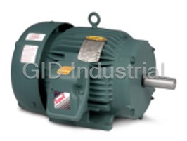
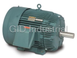


What they say about us
FANTASTIC RESOURCE
One of our top priorities is maintaining our business with precision, and we are constantly looking for affiliates that can help us achieve our goal. With the aid of GID Industrial, our obsolete product management has never been more efficient. They have been a great resource to our company, and have quickly become a go-to supplier on our list!
Bucher Emhart Glass
EXCELLENT SERVICE
With our strict fundamentals and high expectations, we were surprised when we came across GID Industrial and their competitive pricing. When we approached them with our issue, they were incredibly confident in being able to provide us with a seamless solution at the best price for us. GID Industrial quickly understood our needs and provided us with excellent service, as well as fully tested product to ensure what we received would be the right fit for our company.
Fuji
HARD TO FIND A BETTER PROVIDER
Our company provides services to aid in the manufacture of technological products, such as semiconductors and flat panel displays, and often searching for distributors of obsolete product we require can waste time and money. Finding GID Industrial proved to be a great asset to our company, with cost effective solutions and superior knowledge on all of their materials, it’d be hard to find a better provider of obsolete or hard to find products.
Applied Materials
CONSISTENTLY DELIVERS QUALITY SOLUTIONS
Over the years, the equipment used in our company becomes discontinued, but they’re still of great use to us and our customers. Once these products are no longer available through the manufacturer, finding a reliable, quick supplier is a necessity, and luckily for us, GID Industrial has provided the most trustworthy, quality solutions to our obsolete component needs.
Nidec Vamco
TERRIFIC RESOURCE
This company has been a terrific help to us (I work for Trican Well Service) in sourcing the Micron Ram Memory we needed for our Siemens computers. Great service! And great pricing! I know when the product is shipping and when it will arrive, all the way through the ordering process.
Trican Well Service
GO TO SOURCE
When I can't find an obsolete part, I first call GID and they'll come up with my parts every time. Great customer service and follow up as well. Scott emails me from time to time to touch base and see if we're having trouble finding something.....which is often with our 25 yr old equipment.
ConAgra Foods