

 Manufacturers
BALDOR BSC-1105
Description
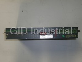
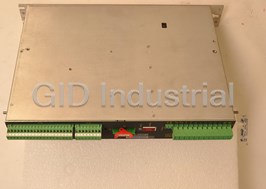
Baldor BSC-1105 Servo Drive - BSC Series 1105 Servo Control Assembly for Brushless AC Motors
Part Number
BSC-1105
Price
Request Quote
Manufacturer
BALDOR
Lead Time
Request Quote
Category
SERVO DRIVES / CONTROLLERS
Specifications
Analog Command Input
±10 VDC
Balance (Offset Drift) RPM
Adjustable to 0
Efficiency
>95%
Minimum Load Inductance
200µH
Mounting
Panel
Nominal Switching Frequency
8.5kHz
Resolver Signal Resolution
12Bits
Speed Command Potentiometer
5k or 10k, 0.5watt
Weight
10.0 lb. | (4.54) kg
Features
- AWG(USA): 14
- Continuous Output Amps (RMS): 5
- Input Fuse (A): 10
- mm2(Europe): 2.5
- Nominal Input Voltage: 230V
Datasheet

Extracted Text
BSC Series 1000/1100 Servo Control for Brushless AC Motors Installation & Operating Manual 7/01 MN1202 Table of Contents Section 1 General Information . . . . . . . . . . . . . . . . . . . . . . . . . . . . . . . . . . . . . . . . . . . . . . . . . . . . . . . . . . . . . . . . . . . . . . . . . . . . . . . 1-1 CE Compliance . . . . . . . . . . . . . . . . . . . . . . . . . . . . . . . . . . . . . . . . . . . . . . . . . . . . . . . . . . . . . . . . . . . . . . . . . . . . . . . . 1-1 Limited Warranty . . . . . . . . . . . . . . . . . . . . . . . . . . . . . . . . . . . . . . . . . . . . . . . . . . . . . . . . . . . . . . . . . . . . . . . . . . . . . . . 1-1 Product Notice . . . . . . . . . . . . . . . . . . . . . . . . . . . . . . . . . . . . . . . . . . . . . . . . . . . . . . . . . . . . . . . . . . . . . . . . . . . . . . . . . 1-2 Safety Notice . . . . . . . . . . . . . . . . . . . . . . . . . . . . . . . . . . . . . . . . . . . . . . . . . . . . . . . . . . . . . . . . . . . . . . . . . . . . . . . . . . 1-2 Section 2 Product Overview . . . . . . . . . . . . . . . . . . . . . . . . . . . . . . . . . . . . . . . . . . . . . . . . . . . . . . . . . . . . . . . . . . . . . . . . . . . . . . . . . 2-1 Section 3 Installation . . . . . . . . . . . . . . . . . . . . . . . . . . . . . . . . . . . . . . . . . . . . . . . . . . . . . . . . . . . . . . . . . . . . . . . . . . . . . . . . . . . . . . . 3-1 Receiving & Inspection . . . . . . . . . . . . . . . . . . . . . . . . . . . . . . . . . . . . . . . . . . . . . . . . . . . . . . . . . . . . . . . . . . . . . . . . . 3-1 Location Considerations . . . . . . . . . . . . . . . . . . . . . . . . . . . . . . . . . . . . . . . . . . . . . . . . . . . . . . . . . . . . . . . . . . . . . . . . 3-1 Mechanical Installation . . . . . . . . . . . . . . . . . . . . . . . . . . . . . . . . . . . . . . . . . . . . . . . . . . . . . . . . . . . . . . . . . . . . . . . . . 3-1 Electrical Installation . . . . . . . . . . . . . . . . . . . . . . . . . . . . . . . . . . . . . . . . . . . . . . . . . . . . . . . . . . . . . . . . . . . . . . . . . . . 3-2 System Grounding . . . . . . . . . . . . . . . . . . . . . . . . . . . . . . . . . . . . . . . . . . . . . . . . . . . . . . . . . . . . . . . . . . . . . . . . . 3-2 Power Disconnect . . . . . . . . . . . . . . . . . . . . . . . . . . . . . . . . . . . . . . . . . . . . . . . . . . . . . . . . . . . . . . . . . . . . . . . . . 3-3 Protection Devices . . . . . . . . . . . . . . . . . . . . . . . . . . . . . . . . . . . . . . . . . . . . . . . . . . . . . . . . . . . . . . . . . . . . . . . . . 3-3 AC Power Connections . . . . . . . . . . . . . . . . . . . . . . . . . . . . . . . . . . . . . . . . . . . . . . . . . . . . . . . . . . . . . . . . . . . . . 3-4 Motor Connections . . . . . . . . . . . . . . . . . . . . . . . . . . . . . . . . . . . . . . . . . . . . . . . . . . . . . . . . . . . . . . . . . . . . . . . . . 3-6 M-Contactor . . . . . . . . . . . . . . . . . . . . . . . . . . . . . . . . . . . . . . . . . . . . . . . . . . . . . . . . . . . . . . . . . . . . . . . . . . . . . . 3-7 BUS Power . . . . . . . . . . . . . . . . . . . . . . . . . . . . . . . . . . . . . . . . . . . . . . . . . . . . . . . . . . . . . . . . . . . . . . . . . . . . . . . 3-7 Dynamic Brake Resistor . . . . . . . . . . . . . . . . . . . . . . . . . . . . . . . . . . . . . . . . . . . . . . . . . . . . . . . . . . . . . . . . . . . . 3-7 24VDC Logic Power . . . . . . . . . . . . . . . . . . . . . . . . . . . . . . . . . . . . . . . . . . . . . . . . . . . . . . . . . . . . . . . . . . . . . . . 3-7 Resolver Feedback . . . . . . . . . . . . . . . . . . . . . . . . . . . . . . . . . . . . . . . . . . . . . . . . . . . . . . . . . . . . . . . . . . . . . . . . 3-8 Simulated Encoder Output . . . . . . . . . . . . . . . . . . . . . . . . . . . . . . . . . . . . . . . . . . . . . . . . . . . . . . . . . . . . . . . . . . 3-8 X2 Control I/O Connections . . . . . . . . . . . . . . . . . . . . . . . . . . . . . . . . . . . . . . . . . . . . . . . . . . . . . . . . . . . . . . . . . 3-9 Section 4 Switch Setting and Start-Up . . . . . . . . . . . . . . . . . . . . . . . . . . . . . . . . . . . . . . . . . . . . . . . . . . . . . . . . . . . . . . . . . . . . . . . . 4-1 Introduction . . . . . . . . . . . . . . . . . . . . . . . . . . . . . . . . . . . . . . . . . . . . . . . . . . . . . . . . . . . . . . . . . . . . . . . . . . . . . . . . . . . 4-1 DIP Switch Settings . . . . . . . . . . . . . . . . . . . . . . . . . . . . . . . . . . . . . . . . . . . . . . . . . . . . . . . . . . . . . . . . . . . . . . . . . . . . 4-1 Potentiometer Initial Settings . . . . . . . . . . . . . . . . . . . . . . . . . . . . . . . . . . . . . . . . . . . . . . . . . . . . . . . . . . . . . . . . . . . . 4-1 Identity Module . . . . . . . . . . . . . . . . . . . . . . . . . . . . . . . . . . . . . . . . . . . . . . . . . . . . . . . . . . . . . . . . . . . . . . . . . . . . . . . . 4-2 Start–up Procedure . . . . . . . . . . . . . . . . . . . . . . . . . . . . . . . . . . . . . . . . . . . . . . . . . . . . . . . . . . . . . . . . . . . . . . . . . . . . 4-3 Power Off Checks . . . . . . . . . . . . . . . . . . . . . . . . . . . . . . . . . . . . . . . . . . . . . . . . . . . . . . . . . . . . . . . . . . . . . . . . . 4-3 Power On Checks . . . . . . . . . . . . . . . . . . . . . . . . . . . . . . . . . . . . . . . . . . . . . . . . . . . . . . . . . . . . . . . . . . . . . . . . . 4-3 Adjustment Procedure . . . . . . . . . . . . . . . . . . . . . . . . . . . . . . . . . . . . . . . . . . . . . . . . . . . . . . . . . . . . . . . . . . . . . . . . . . 4-4 MN1202 Table of Contents i Section 5 Troubleshooting . . . . . . . . . . . . . . . . . . . . . . . . . . . . . . . . . . . . . . . . . . . . . . . . . . . . . . . . . . . . . . . . . . . . . . . . . . . . . . . . . . 5-1 Overview . . . . . . . . . . . . . . . . . . . . . . . . . . . . . . . . . . . . . . . . . . . . . . . . . . . . . . . . . . . . . . . . . . . . . . . . . . . . . . . . . . . . . 5-1 BPS Troubleshooting Procedure . . . . . . . . . . . . . . . . . . . . . . . . . . . . . . . . . . . . . . . . . . . . . . . . . . . . . . . . . . . . . . . . . 5-1 Electrical Noise Considerations . . . . . . . . . . . . . . . . . . . . . . . . . . . . . . . . . . . . . . . . . . . . . . . . . . . . . . . . . . . . . . . . . . 5-2 Section 6 Specifications and Product Data . . . . . . . . . . . . . . . . . . . . . . . . . . . . . . . . . . . . . . . . . . . . . . . . . . . . . . . . . . . . . . . . . . . 6-1 Identification . . . . . . . . . . . . . . . . . . . . . . . . . . . . . . . . . . . . . . . . . . . . . . . . . . . . . . . . . . . . . . . . . . . . . . . . . . . . . . . . . . 6-1 Specifications . . . . . . . . . . . . . . . . . . . . . . . . . . . . . . . . . . . . . . . . . . . . . . . . . . . . . . . . . . . . . . . . . . . . . . . . . . . . . . . . . 6-2 Dimensions & Mounting . . . . . . . . . . . . . . . . . . . . . . . . . . . . . . . . . . . . . . . . . . . . . . . . . . . . . . . . . . . . . . . . . . . . . . . . . 6-4 Section 7 CE Guidelines . . . . . . . . . . . . . . . . . . . . . . . . . . . . . . . . . . . . . . . . . . . . . . . . . . . . . . . . . . . . . . . . . . . . . . . . . . . . . . . . . . . . 7-1 CE Declaration of Conformity . . . . . . . . . . . . . . . . . . . . . . . . . . . . . . . . . . . . . . . . . . . . . . . . . . . . . . . . . . . . . . . . . . . . 7-1 EMC – Conformity and CE – Marking . . . . . . . . . . . . . . . . . . . . . . . . . . . . . . . . . . . . . . . . . . . . . . . . . . . . . . . . . . . . . 7-1 EMC Installation Instructions . . . . . . . . . . . . . . . . . . . . . . . . . . . . . . . . . . . . . . . . . . . . . . . . . . . . . . . . . . . . . . . . . . . 7-3 ii Table of Contents MN1202 Section 1 General Information Copyright Baldor 1997, 1999, 2000, 2001. All rights reserved. This manual is copyrighted and all rights are reserved. This document may not, in whole or in part, be copied or reproduced in any form without the prior written consent of Baldor. Baldor makes no representations or warranties with respect to the contents hereof and specifically disclaims any implied warranties of fitness for any particular purpose. The information in this document is subject to change without notice. Baldor assumes no responsibility for any errors that may appear in this document. Microsoft and MS–DOS are registered trademarks, and Windows is a trademark of Microsoft Corporation. UL and cUL are registered trademarks of Underwriters Laboratories. CE Compliance A custom unit may be required, contact Baldor. Compliance to Directive 89/336/EEC is the responsibility of the system integrator. A control, motor and all system components must have proper shielding, grounding, and filtering as described in MN1383. Please refer to MN1383 for installation techniques for CE compliance. For additional information, refer to Sections 3 and 7 of this manual. Limited Warranty For a period of two (2) years from the date of original purchase, BALDOR will repair or replace without charge controls and accessories which our examination proves to be defective in material or workmanship. This warranty is valid if the unit has not been tampered with by unauthorized persons, misused, abused, or improperly installed and has been used in accordance with the instructions and/or ratings supplied. This warranty is in lieu of any other warranty or guarantee expressed or implied. BALDOR shall not be held responsible for any expense (including installation and removal), inconvenience, or consequential damage, including injury to any person or property caused by items of our manufacture or sale. (Some states do not allow exclusion or limitation of incidental or consequential damages, so the above exclusion may not apply.) In any event, BALDOR’s total liability, under all circumstances, shall not exceed the full purchase price of the control. Claims for purchase price refunds, repairs, or replacements must be referred to BALDOR with all pertinent data as to the defect, the date purchased, the task performed by the control, and the problem encountered. No liability is assumed for expendable items such as fuses. Goods may be returned only with written notification including a BALDOR Return Authorization Number and any return shipments must be prepaid. MN1202 General Information 1-1 Product Notice Intended use: These drives are intended for use in stationary ground based applications in industrial power installations according to the standards EN60204 and VDE0160. They are designed for machine applications that require variable speed controlled three phase brushless AC motors. These drives are not intended for use in applications such as: – Home appliances – Medical instrumentation – Mobile vehicles – Ships – Airplanes Unless otherwise specified, this drive is intended for installation in a suitable enclosure. The enclosure must protect the control from exposure to excessive or corrosive moisture, dust and dirt or abnormal ambient temperatures. The exact operating specifications are found in Section 6 of this manual. The installation, connection and control of drives is a skilled operation, disassembly or repair must not be attempted. In the event that a control fails to operate correctly, contact the place of purchase for return instructions. Safety Notice: This equipment contains high voltages. Electrical shock can cause serious or fatal injury. Only qualified personnel should attempt the start–up procedure or troubleshoot this equipment. This equipment may be connected to other machines that have rotating parts or parts that are driven by this equipment. Improper use can cause serious or fatal injury. Only qualified personnel should attempt the start–up procedure or troubleshoot this equipment. – System documentation must be available at all times. – Keep non-qualified personnel at a safe distance from this equipment. – Only qualified personnel familiar with the safe installation, operation and maintenance of this device should attempt start-up or operating procedures. – Always remove power before making or removing any connections to this control. PRECAUTIONS: Classifications of cautionary statements. WARNING: Indicates a potentially hazardous situation which, if not avoided, could result in injury or death. Caution: Indicates a potentially hazardous situation which, if not avoided, could result in damage to property. Continued on next page. MN1202 1-2 General Information WARNING: Do not touch any circuit board, power device or electrical connection before you first ensure that power has been disconnected and there is no high voltage present from this equipment or other equipment to which it is connected. Electrical shock can cause serious or fatal injury. WARNING: Be sure that you are completely familiar with the safe operation of this equipment. This equipment may be connected to other machines that have rotating parts or parts that are controlled by this equipment. Improper use can cause serious or fatal injury. WARNING: Be sure all wiring complies with the National Electrical Code and all regional and local codes or CE Compliance. Improper wiring may cause a hazardous condition. WARNING: Be sure the system is properly grounded before applying power. Do not apply AC power before you ensure that grounds are connected. Electrical shock can cause serious or fatal injury. WARNING: Do not remove cover for at least five (5) minutes after AC power is disconnected to allow capacitors to discharge. Electrical shock can cause serious or fatal injury. WARNING: Improper operation of control may cause violent motion of the motor shaft and driven equipment. Be certain that unexpected motor shaft movement will not cause injury to personnel or damage to equipment. Peak torque of several times the rated motor torque can occur during control failure. WARNING: Motor circuit may have high voltage present whenever AC power is applied, even when motor is not rotating. Electrical shock can cause serious or fatal injury. WARNING: If a motor is driven mechanically, it may generate hazardous voltages that are conducted to its power input terminals. The enclosure must be grounded to prevent a possible shock hazard. WARNING: When operating a motor with no load coupled to its shaft, remove the shaft key to prevent injury if it were to fly out when the shaft rotates. WARNING: The motor shaft will rotate during the autotune procedure. Be certain that unexpected motor shaft movement will not cause injury to personnel or damage to equipment. WARNING: A DB Resistor may generate enough heat to ignite combustible materials. To avoid fire hazard, keep all combustible materials and flammable vapors away from brake resistors. WARNING: The user must provide an external hard-wired emergency stop circuit to disable the control in the event of an emergency. Caution: Suitable for use on a circuit capable of delivering not more than the RMS symmetrical short circuit amperes listed here at rated voltage. Horsepower RMS Symmetrical Amperes 1–50 5,000 Caution: To prevent equipment damage, be certain that the input power has correctly sized protective devices installed as well as a power disconnect. Continued on next page. MN1202 General Information 1-3 Caution: Avoid locating control immediately above or beside heat generating equipment, or directly below water or steam pipes. Caution: Avoid locating control in the vicinity of corrosive substances or vapors, metal particles and dust. Caution: For UL installations, do not connect any resolver cable shields to the motor frame. At a minimum, resolver signal integrity will be compromised and damage to the control may result. For CE installations, refer to CE guidelines stated in Sections 3 and 7 of this manual. Caution: Do not connect AC power to the control terminals U, V and W. Connecting AC power to these terminals may result in damage to the control. Caution: Baldor recommends not using “Grounded Leg Delta” transformer power leads that may create ground loops and degrade system performance. Instead, we recommend using a four wire Wye. Caution: Logic signals are interruptible signals; these signals are removed when power is removed from the drive. Caution: Controls are intended to be connected to a permanent main power source, not a portable power source. Suitable fusing and circuit protection devices are required. Caution: The safe integration of the drive into a machine system is the responsibility of the machine designer. Be sure to comply with the local safety requirements at the place where the machine is to be used. In Europe this is the Machinery Directive, the ElectroMagnetic Compatibility Directive and the Low Voltage Directive. In the United States this is the National Electrical code and local codes. Caution: Controls must be installed inside an electrical cabinet that provides environmental control and protection. Installation information for the drive is provided in this manual. Motors and controlling devices that connect to the drive should have specifications compatible to the drive. Caution: Violent jamming (stopping) of the motor shaft during operation may damage the motor and control. Caution: Do not tin (solder) exposed wires. Solder contracts over time and may cause loose connections. Caution: Electrical components can be damaged by static electricity. Use ESD (electro-static discharge) procedures when handling this control. Caution: Ensure that resolver or encoder wires are properly connected. Incorrect installation may result in improper rotation or incorrect commutation. Caution: The holes in the top and bottom of the enclosure are for cable clamps. Be sure to use an M4 bolt 12mm in length. Longer bolts may short circuit the electrical components inside the control. MN1202 1-4 General Information Section 2 Product Overview Overview The BSC product is designed to serve the needs of machine designers and manufacturers. Baldor products have both UL and CE approvals. Motors Baldor servo controls are compatible with many motors from Baldor and other manufacturers. Motor parameters are provided with the PC software making the setup easy. Baldor compatible motors include: � BSM–4R / 63A / 80A / 80B Series motors � BSM–6R Series motors � BSM–4F / 6F / 8F / 90A / 90B Series motors General Information The BSC1000/1100 is a resolver based servo control designed to be used with brushless servo motors. The control accepts a standard ±10 VDC to control brushless servo motors in either a velocity or current (torque) loop. The standard BSC 1100 series includes an internal power supply; the standard BSC 1000 series requires an external supply. Physically, the two units are identical. MN1202 Product Overview 2-1 2-2 Product Overview MN1202 Section 3 Installation Receiving & Inspection Baldor Controls are thoroughly tested at the factory and carefully packaged for shipment. When you receive your control, there are several things you should do immediately. 1. Observe the condition of the shipping container and report any damage immediately to the commercial carrier that delivered your control. 2. Remove the control from the shipping container and remove all packing materials. The container and packing materials may be retained for future shipment. 3. Verify that the part number of the control you received is the same as the part number listed on your purchase order. 4. Inspect the control for external physical damage that may have been sustained during shipment and report any damage immediately to the commercial carrier that delivered your control. 5. If the control is to be stored for several weeks before use, be sure that it is stored in a location that conforms to published storage humidity and temperature specifications stated in this manual. Location Considerations The location of the control is important. Installation should be in an area that is protected from direct sunlight, corrosives, harmful gases or liquids, dust, metallic particles, and vibration. Exposure to these can reduce the operating life and degrade performance of the control. Several other factors should be carefully evaluated when selecting a location for installation: 1. For effective cooling and maintenance, the control should be mounted on a smooth, non-flammable vertical surface. 2. At least 0.6 inches (15mm) top and bottom clearance must be provided for air flow. Refer to Section 6 for mounting dimensions. 3. Altitude derating. Up to 3300 feet (1000 meters) no derating required. Derate the continuous and peak output current by 1.1% for each 330 feet (100 meters) above 3300 feet. 4. Temperature derating. From 5°C to 45°C ambient no derating required. Above 45°C, derate the continuous and peak output current by 2.9% per °C above 45°C. Maximum ambient is 55°C. Mechanical Installation Mount the control to the mounting surface. The control must be securely fastened to the mounting surface by the control mounting holes. The location of the mounting holes is shown in Section 6 of this manual. Power Loss Ratings Control Type 1002 1005 1010 1015 Power Loss (Watts) 19 19 54 85 (For BSC11XX units, add 55Watts) MN1202 Installation 3-1 Electrical Installation All interconnection wires between the control, AC power source, motor, host control and any operator interface stations should be in metal conduits. Use listed closed loop connectors that are of appropriate size for wire gauge being used. Connectors are to be installed using crimp tool specified by the manufacturer of the connector. Only class 1 wiring should be used. System Grounding Baldor controls are designed to be powered from standard single and three phase lines that are electrically symmetrical with respect to ground. System grounding is an important step in the overall installation to prevent problems. The recommended grounding method is shown in Figure 3-1 for UL compliant systems (Figure 3-2 for CE compliant systems). Figure 3-1 Recommended System Grounding (3 phase) for UL L1 Note: Control Wiring shown for clarity of grounding method only. AC Main L1 L2 L3 PE U V W L2 Not representative of actual Supply terminal block location. L3 Earth Safety Route all power wires L1, L2, L3 and Earth Four Wire Ground (Ground) together in conduit or cable. “Wye” Driven Earth Ground Rod (Plant Ground) Note: Use shielded cable for control signal wires. Route control signal wires in conduit. These wires must be Ground per NEC and Local codes. kept separate from power and motor wires. Figure 3-2 Recommended System Grounding (3 phase) for CE L1 Note: AC Main Control Wiring shown for clarity of Supply L1 L2 L3 PE U V W grounding method only. L2 Not representative of actual Four Wire terminal block location. “Wye” L3 PE Safety Ground Route all power wires Motor L1, L2, L3 and Earth GND (Ground) together in conduit or cable. All shields Enclosure Backplane (see Section 6) Note: Use shielded cable for control signal wires. Route control signal wires in conduit. These wires must be kept separate from power and motor wires. 3-2 Installation MN1202 System Grounding Continued Ungrounded Distribution System With an ungrounded power distribution system it is possible to have a continuous current path to ground through the MOV devices. To avoid equipment damage, an isolation transformer with a grounded secondary is recommended. This provides three phase AC power that is symmetrical with respect to ground. Input Power Conditioning Baldor controls are designed for direct connection to standard single and three phase lines that are electrically symmetrical with respect to ground. Certain power line conditions must be avoided. An AC line reactor or an isolation transformer may be required for some power conditions. • If the feeder or branch circuit that provides power to the control has permanently connected power factor correction capacitors, an input AC line reactor or an isolation transformer must be connected between the power factor correction capacitors and the control. • If the feeder or branch circuit that provides power to the control has power factor correction capacitors that are switched on line and off line, the capacitors must not be switched while the control is connected to the AC power line. If the capacitors are switched on line while the control is still connected to the AC power line, additional protection is required. TVSS (Transient Voltage Surge Suppressor) of the proper rating must be installed between the AC line reactor or an isolation transformer and the AC input to the control. Power Disconnect A power disconnect should be installed between the input power service and the control for a fail–safe method to disconnect power. The control will remain in a powered-up condition until all input power is removed from the control and the internal bus voltage is depleted. Protection Devices The control must have a suitable input power protection device installed. Input and output wire size is based on the use of copper conductor wire rated at 75 °C. Table 3-1 describes the wire size to be used for power connections and the ratings of the protection devices. Table 3-1 Wire Size and Protection Devices Catalog Number Incoming Power Input Fuse Wire Gauge Continuous Continuous Nominal Input 2 Output AWG mm Voltage (A) Amps (RMS) (USA) (Europe) BSC1002 � – 2 6 14 2.5 BSC1102 115V (3�) 2 6 14 2.5 BSC1105–1 115V (1�) 5 10 14 2.5 BSC1005 � – 5 10 14 2.5 BSC1105 230V (3�) 5 10 14 2.5 BSC1110–1 115V (1�) 10 20 12 2.5 BSC1010 � – 10 20 12 2.5 BSC1110 230V (3�) 10 20 12 2.5 BSC1115–1 15 30 10 5.26 115V (1�) BSC1015 � – 15 30 10 5.26 BSC1115 15 30 10 5.26 230V (3�) Note: All wire sizes are based on 75°C copper wire. Higher temperature smaller gauge wire may be used per NEC and local codes. Recommended fuses/breakers are based on 25°C ambient, maximum continuous control output current and no harmonic current. � Requires separate DC Bus input voltage. No AC input or internal power supply available in this model. MN1202 Installation 3-3 AC Power Connections The location of the X7 connector is shown in Figure 3-6. Each BSC control must be fused separately. All interconnection wires between the control, AC power source, motor and any operator interface stations should be in metal conduits. Only class 1 wiring should be used. Wire and Fuses should be of the correct size specified in Table 3-1. Connect the AC power connections as shown in Figures 3-3 (three phase) or 3-4 (single phase). For single phase installations, do not connect any wires to L3. Figure 3-3 3 Phase Power Connections L1 L2 L3 Earth Note 1 Note 3 & 4 * Fuse * Components not provided with Control. Notes: Connections 1. See Protection Device description in this section. Note 2 2. Metal conduit or shielded cable should be used. Connect conduits so the use of a Reactor or RC Device does not interrupt L1 L2 L3 PE EMI/RFI shielding. 3. Use the same gauge wire for Earth as used for L1, L2, L3 connections. 3. Use same gauge wire for Earth ground as is used for L and N. Baldor 2 (VDE (Germany) requires 10mm minimum). For CE Control compliance, connect “PE” to the backplane of the enclosure. 4. Reference EMC wiring in Section 7. Figure 3-4 Single Phase Power Connections (115V 1� only) LN Earth Note 1 Note 3 & 4 * Fuse * Components not provided with Control. Notes: Connections 1. See Protection Device description in this section. Note 2 2. Metal conduit or shielded cable should be used. Connect conduits so the use of a Reactor or RC Device does not interrupt L1 L2 L3 PE EMI/RFI shielding. 3. Use the same gauge wire for Earth as used for L1 and L2 connections. Baldor 3. Use same gauge wire for Earth ground as is used for L and N. 2 Control (VDE (Germany) requires 10mm minimum). For CE compliance, connect “PE” to the backplane of the enclosure. 4. Reference EMC wiring in Section 7. 3-4 Installation MN1202 Figure 3-5 Single Phase Power Connections (230V 1� only) L1 L2 Earth Note 1 Note 3 & 4 * Fuse * Components not provided with Control. Notes: Connections 1. See Protection Device description in this section. Note 2 2. Metal conduit or shielded cable should be used. Connect conduits so the use of a Reactor or RC Device does not interrupt L1 L2 L3 PE EMI/RFI shielding. 3. Use the same gauge wire for Earth as used for L1 and L2 connections. Baldor 3. Use same gauge wire for Earth ground as is used for L and N. 2 Control (VDE (Germany) requires 10mm minimum). For CE compliance, connect “PE” to the backplane of the enclosure. 4. Reference EMC wiring in Section 7. MN1202 Installation 3-5 1 234 5 6 Figure 3-6 Connector Locations PE (Power Ground) X7 X1 - Power Connector �� PE Earth Ground �� L1 Phase 1 Input �� AC Input Power L2 Phase 2 Input � L3 Phase 3 Input � U Motor lead “U” Motor Connections V Motor lead “V” � W Motor lead “W” ���� VCC+ Bus Power Bus power for ���� VCC– Bus Power BSC1000 etc. �� R1 Dynamic Brake Dynamic Brake �� R2 Dynamic Brake (Regen Resistor) +24V Customer ���� Logic Power input * 0V Provided �� Reg. load * Only connect 24VDC to logic power input if option is installed. If option is not installed, connecting 24VDC to these terminals can cause damage to the control. Monitor Enable ID 12 3 4 Current limit switches are accessed through a hole in the side panel in the approximate area shown. P 1 �������������� X3 X3 – Resolver 3 ������������� 1 Ref+ 5 Sine+ 2 Ref– 6 Sine– 4 ������������������ 3 Cos+ 7 Not Used 5 ������������������ 4 Cos– 8 DGND 6 ������� ��� ON X2 DIP Switches (Motor select) X2 – Control I/O 1 CMD+ 11 CWLimit 2 CMD– 12 CCWLimit X5 – Simulated Encoder Output 3 AGND 13 Current C 1 Not Used 6 CHB– X5 4 +15VDC 14 CREF 2 Not Used 7 CHA+ 5 –15VDC 15 Fault+ 3 CHC– 8 CHB+ 6 Speed 16 Fault– 4 CHC+ 9 DGND 7 DCurrent 17 Warn_C 5 CHA– 8 Icmd 18 Warn_E 9 Enable 19 Reset 10 EMStop 20 DGND Signal Ground (Shields) 3-6 Installation MN1202 Off ON Motor Connections Motor connections are shown in Figure 3-7. (Connections U, V and W are shown in Figure 3-6). If connected wrong, erratic operation including moves at peak force may occur until the overcurrent limit trips. If erratic movement of the motor occurs, turn off power immediately and check the connections of the motor. Figure 3-7 Motor Connections for U.L. Notes: 1. Metal conduit or shielded cable should be used. Connect conduits so the use of Load Reactor* or RC Device* does Baldor not interrupt EMI/RFI shielding. Control 2. Use same gauge wire for Earth ground as is used for the 2 L1, L2 and L3. (VDE (Germany) requires 10mm minimum, PE UV W 6AWG). For CE compliance, connect motor ground to the backplane of the enclosure. Note 1 3. Reference EMC wiring in Section 7. 4. Motor and resolver are phase sensitive. Connect only as Note 2 instructed. VW This is the ground post on the top cover. U G * Optional components not provided with control. * AC Servo Motor Figure 3-8 Motor Connections for CE Notes: 1. Metal conduit or shielded cable should be used. Connect conduits so the use of Load Reactor* or RC Device* does not interrupt EMI/RFI shielding. Baldor 2. Use same gauge wire for Earth ground as is used for Control 2 the L1, L2 and L3. (VDE (Germany) requires 10mm This is the minimum, 6AWG). For CE compliance, connect motor ground post on the top cover. ground to the backplane of the enclosure. UV W PE 3. Reference EMC wiring in Section 7. Note 1 4. Motor and resolver are phase sensitive. Connect only as instructed. VW Note 2 U G Enclosure Backplane (see Section 7) * Optional components not provided with control. * AC Servo Motor Note: For CE compliant installations, connect unused leads within the motor cable to “PE” on both ends of the cable. MN1202 Installation 3-7 M-Contactor If required by local codes or for safety reasons, an M-Contactor (motor circuit contactor) may be installed. However, incorrect installation or failure of the M-contactor or wiring may damage the control. If an M-Contactor is installed, the control must be disabled for at least 20msec before the M-Contactor is opened or the control may be damaged. M-Contactor connections are shown in Figure 3-9. Figure 3-9 Optional M-Contactor Connections UV W * RC Device * M-Contactor To Power Source Electrocube RG1781-3 (Rated Coil Voltage) This is the * MM M ground post on the top cover. * Optional components not provided with control. Note 1 and 2 VW X2 * U G M Enable Note: Close “Enable” * Motor 9 after “M” contact closure. M=Contacts of optional M-Contactor Notes: 1. Use same gauge wire for Earth ground as is used for the BPS L1, L2 and L3. (VDE 2 (Germany) requires10mm minimum, 6AWG). 2. For UL installations, connect motor ground to of the control as shown. For CE installations, connect motor ground to the enclosure backplane (see Figure 3-8). BUS Power For multi–axis applications, the second control may not have an internal supply. Bus power for the second control can be connected as shown in Figure 3-10. Figure 3-10 A control with an internal supply can provide bus power to a ()*���� ()*���� maximum of one control that requires an external power &’ &’ source. Simply connect the X7 VCC+ of the first control to ���� ���� the VCC+ of the second control. Then connect the X7 VCC– ���� ���� of the first control to the VCC– of the second control. ���� ������!� ��"�� �#�$%�� ������!� Dynamic Brake Resistor An external DB (dynamic brake or regen resistor) resistor is required to dissipate excess power from the DC bus during motor deceleration operations. An external 320 watt resistor must be connected at the X7 terminals R1 and R2. Refer to Section 6 for selection information or contact Baldor. 24VDC Logic Power If the control is equipped with the internal 24VDC logic power circuit (BSC1XXX–24–X), 24VDC may be connected to this input to maintain voltage on the logic circuits at all times. An external 24VDC (20V to 60V source) supply must be used. This supply must remain on when AC power to the control is disconnected. Connect the power supply leads to X7 input terminals +24V and 0V. Note: All units are marked 24V and 0V. Do not connect an external 24VDC source to these terminals unless the control is equipped with the internal 24VDC logic power circuit (BSC1XXX–24–X). 3-8 Installation MN1202 Resolver Feedback The resolver connections are made at the X3 connector as shown in Figure 3-11 or 3-12. 2 The resolver cable must be shielded twisted pair #22 AWG (0.34mm ) wire minimum. The cable must also have an overall shield. Maximum wire-to-wire or wire-to-shield capacitance is 50pf per foot. Resolver wiring must be separated from power wiring. Separate parallel runs of resolver and power cables by at least 3″. Cross power wires at right angles only. Insulate or tape ungrounded end of shields to prevent contact with other conductors or ground. Note: Motor and resolver are phase sensitive. Connect only as instructed. Figure 3-11 Resolver Cable Connections for UL Installations R2 S2 X3 P 5 SIN+ R1 S4 6 SIN- P 3 COS+ S3 S1 4 COS- P 1 REF+ 2 REF- (Common) P Shields = Twisted Pair Shell (Chassis) Figure 3-12 Resolver Cable Connections for CE Installations R2 S2 X3 P 5 SIN+ R1 S4 6 SIN- P 3 COS+ S3 S1 4 COS- P 1 REF+ P 2 REF- (Common) PE PE = Twisted Pair Simulated Encoder Output The control provides a simulated encoder output at connector X5. This output may be used by external hardware to monitor the encoder signals. It is recommended that this output only drive one circuit load. Refer to Table 3-2. Table 3-2 Simulated Encoder Output at X5 Connector X5 Pin Signal Name 1 Not Used 2 Not Used 3 CHC– 4 CHC+ 5 CHA– 6 CHB– 7 CHA+ 8 CHB+ 9 DGND Shell * Chassis (Cable Shield) * For UL Installations ONLY. For CE Installations, connect the outer shield on each end of the cable to the signal ground (shields) at the bottom of the control. MN1202 Installation 3-9 X2 Control I/O Connections 18AWG wire is sufficient for all X2 connections. Analog I/O Command Input X3 pins 1, 2 and 3 allows connection of an external analog command input. This input can accept a 0-10VDC or ±10VDC signal and can be wired as a single ended or differential input, shown in Figure 3-13. Figure 3-13 Control Input Wiring Single Ended Connection Differential Connection X2 X2 + 1 CMD+ 1 CMD+ Single Ended Signal Signal 2 CMD- 2 CMD- Source Source CW operation AGND AGND as shown 3 3 15VDC Output X2 pins 4 and 5 provide 15VDC output @100mA maximum. (X2–3 is common). Speed Output X2 pins 6 provides a motor velocity test point. (X2–3 is common). Motor RPM = VDC X 600 Output Current X2 pins 7 provides a test point to measure actual motor current. (X2–3 is common). Scaled 0 to 10VDC (where 10VDC = I ) peak Icmd X2 pins 7 provides a test point to measure commanded motor current. (X2–3 is common). Scaled ±10VDC (where ±10VDC = I ) peak Figure 3-14 Reset Wiring X2 Close X2–19 to reset an over voltage, under voltage, over current, over temperature, Reset 19 2 resolver fault or electronic fusing (I T) fault. DGND 20 3-10 Installation MN1202 Digital I/O X2 Digital Inputs - (uses CREF, X2-14) Active High (Sourcing) - If pin X2-14 is grounded, an input is active when it is at +24VDC (+12VDC to +30VDC). Active Low (Sinking) - If pin X2-14 is at +24VDC (+12VDC to +30VDC), an input is active when it is grounded. Logic input connections are made at terminal strip X2. Input connections can be wired as active High or active Low as shown in Figure 3-15. X2 pin 14 is the Control Reference point (CREF) for the Isolated Input signals. Note: An internal 24VDC power supply connection is not available from the control to power the Input circuits. A customer provided external power source must be used as indicated in Figure 3-15. Figure 3-15 Active HIGH /LOW Relationship Note: All inputs are referenced to CREF, X2-14. Input Active Low Active High (Sink) (Source) X2 +24VDC GND A 14 CREF Input 9 ENABLE B GND +24VDC 10 EMStop A 11 CW-ENABLE 20mA 20mA 12 CCW-ENABLE B +24VDC 9 - 17 GND 9 - 17 B B 13 Current C 7 7 GND +24VDC A A Typical Typical Control Control Source Sink Table 3-1 Digital Input Signal Conditions Pin Signal Switch = Closed (active) Switch = Open (not active) Number Name X2-9 Enable Drive enabled. Drive disabled. X2-10 EMStop (Emergency Stop) Motor enabled. Motor disabled. X2-11 CW-Enable Clockwise rotation enabled. Clockwise rotation disabled. X2-12 CCW-Enable Counter-clockwise rotation enabled. Counter-clockwise rotation disabled. X2-13 Current C (Torque/Velocity) Current mode (Torque). Velocity mode. Current C Use Current mode (X2–13 Closed) for positioning applications. Use Velocity mode (X2–13 Open) for speed control applications. Signal Name Digital Input Signal Definition Enable CLOSED allows normal operation. OPEN disables the control and motor coasts to a stop. EMStop CLOSED allows normal operation. OPEN commands zero velocity and motor coasts to a stop. CW-Enable CLOSED allows normal operation in the CW direction. OPEN to disable CW rotation. The motor decels to a stop. CCW-Enable CLOSED allows normal operation in the CCW direction. OPEN to disable CCW rotation. The motor decels to a stop. Current C CLOSED current mode operation is enabled. OPEN velocity mode operation is enabled. MN1202 Installation 3-11 X2 Digital Outputs The control outputs are located on the X2 connector. A customer provided, external power supply must be used if digital outputs are to be used. The outputs provide status information and are not required for operation. Figure 3-16 Fault Relay Connections 15 Customer provided external power source: and Non-Inductive Load Relay 110VAC @ 0.3A maximum or 24VDC @ 0.8A maximum 16 Contact is closed when power is on Note: and no faults are present. After a fault, the output is reset by closing Control Customer provided interface circuit the reset switch (X2–19 to X2–20). Figure 3-17 Warning “C” and “E” Output Connections + Note: VCC Source Customer must use a current limiting � � (+12VDC to +30VDC) resistor (R ). The minimum value of L R can be calculated as follows: L 17, 18 Output Signal OR VCC Source R minimum � L 0.04 Relay 20 Typical CGND 35mA Customer Provided Interface Circuit Maximum Control Table 3-2 Output Signal Conditions Pin Signal Switch = Closed (active) Switch = Open (not active) Number Name X2-15 Fault + Drive OK - no faults detected. Fault is detected. X2-16 Fault - Drive OK - no faults detected. Fault is detected. 2 X2-17 WarnC No Overcurrent fault detected. I T Overcurrent condition is detected. X2-18 WarnE No Over temperature fault detected. Over temperature condition is detected. Fault Relay A normally closed relay contact that opens if a fault occurs. The contact is rated: 24VDC @ 0.8A maximum or 110VAC @ 0.3A maximum. 2 WarnC Over Current limit (I T electronic fusing warning). Output can be connected to an external alarm circuit. Each output is rated 30VDC @ 35mA maximum. WarnE Overtemperature warning. Output can be connected to an external alarm circuit. This output is rated 30VDC @ 35mA maximum. 3-12 Installation MN1202 1 234 5 6 Section 4 26M Switch Setting and Start-Up Introduction These procedures are performed with the power off. Do not apply power until you are instructed to do so. This means AC power and 24VDC Logic power must both be disconnected. DIP Switch Settings (Refer to Section 3 for location) Motor Select (on front panel) ON Six DIP switches are located on the front panel. Refer to Table 4-1 to determine the correct setting of these switches. Note: All switches are shown in the “ON” position. Table 4-1 Control Address Setting Switch Description 1 2 3 4 5 6 ON OFF OFF For motors BSM 4R / 63A / 80A / 80B OFF ON OFF For motor BSM 6R ON ON OFF For motors BSM 4F / 6F / 8F / 90A / 90B OFF OFF Encoder Simulation of 1024 Pulse per Revolution ON OFF Encoder Simulation of 1000 Pulse per Revolution OFF ON Encoder Simulation of 500 Pulse per Revolution ON ON Encoder Simulation of 250 Pulse per Revolution OFF Off = Integral part of the velocity loop is active. ON On = Proportional loop only (no integral part). Current Limit (on side panel) Current limit switches are accessed through a hole in the side panel. These switches reduce both the continuous and peak current by the same ratio. 1 234 Table 4-2 Current Limit Setting Switch Description 1 2 3 4 OFF OFF OFF OFF 25% of full rated output current ON ON OFF OFF 50% of full rated output current OFF OFF ON ON 75% of full rated output current ON ON ON ON 100% of full rated output current Potentiometer Initial Settings The potentiometers must be pre–set. Refer to Section 3 for location. Set the potentiometers to the pre–set positions indicated in Table 4-3. Table 4-3 Potentiometer Initial Preset Positions Potentiometer Function Initial Setting (Factory settings) P1 Reference Input Gain CW for maximum input gain P3 Velocity Feedback Gain CW for maximum gain P4 Velocity Balance (Drift Adjustment) Standstill at zero point command P5 Velocity Loop Gain (Prop Gain) CCW for minimum gain P6 Peak Current CCW for reduced current MN1202 Switch Setting and Start-Up 4-1 Off ON Identity Module The Identity Module must be fully inserted into its socket to allow control operation. Several components are mounted on this module. Refer to Figure for their location and to Table 4-4 for their description. Note: If the Identity Module is not completely inserted, the unit will not operate. Figure 4-1 Identity Module Component Locations Table 4-4 Identity Module Component Descriptions Component Description Factory Value R38 Speed Scaling (4000 RPM) � 4.99 kΩ D401 Plug–in protection – R94 P–gain for velocity loop 100 kΩ C19 I–gain for velocity loop 47 nF 2 R22 I T–switching threshold (nom. current) � – R765 Special function 26.7 kΩ R43 P–gain for current loop phase U 150 kΩ C17 I–gain for current loop phase U 4.7 nF R44 P–gain for current loop phase V 150 kΩ C11 I–gain for current loop phase V 4.7 nF D402 Plug–in protection – RES Reserved for special applications – � R38 is used to set the maximum speed of the control/motor combination. The standard factory value is a 4.99 kΩ resistor for 4000 RPM. If the motor’s maximum speed for a given application is not 4000 RPM, this resistor should be replaced with one of the following resistor values below depending on the maximum required speed: 0 Ω for 6000 RPM 4.99 kΩ for 4000 RPM 10 kΩ for 3000 RPM 20 kΩ for 2000 RPM Contact Baldor for applications over 6000 RPM. � R22 is used to limit the continuous current of the control (without affecting peak current). 2 The standard factory arrangement is to not insert R22. If an I T limit is desired, the value of R22 can be determined from Table 4-5. 4-2 Switch Setting and Start-Up MN1202 Table 4-5 Current Limit Value Determination Value of R22 BSC 1002/1102 BSC 1005/1105 BSC 1010/1110 BSC 1015/1115 Ohms I = 4A I = 10A I = 20A I = 30A peak peak peak peak Open ( ∞ ) I = 2.0A I = 5.0A I = 10.0A I = 15.0A cont cont cont cont 20kΩ I = 1.6A I = 4.0A I = 8.0A I = 12.0A cont cont cont cont 10kΩ I = 1.3A I = 3.3A I = 6.7A I = 10.0A cont cont cont cont 5kΩ I = 1.0A I = 2.5A I = 5.0A I = 7.5A cont cont cont cont Start–up Procedure Power Off Checks Before you apply power, it is very important to verify the following: 1. Disconnect the load from the motor shaft until instructed to apply a load. If this cannot be done, disconnect the motor wires at X7-U, V and W. 2. Verify that switches are set correctly. 3. Verify the AC line voltage at the source matches the control rated voltage. 4. Inspect all power connections for accuracy, workmanship and tightness. 5. Verify that all wiring conforms to applicable codes. 6. Verify that the control and motor are properly grounded to earth ground. 7. Check all signal wiring for accuracy. Power On Checks If using a transformer, switch the primary side only, and check that the secondary voltage is 115 VAC for single phase units and between 115 VAC and 230 VAC for three phase units. 1. Temporarily disconnect the input speed command signal (±10 VDC) from the Control Signal Connector X2 inputs CMD + (pin 1) and CMD – (pin 2) and jumper the CMD + and CMD – inputs together. 2. Switch on the main power. The motor may run away “out of control” if the resolver wires are connected incorrectly. Turn power off immediately and check resolver wires. If the motor shaft rotates in the wrong direction, check the wiring of the motor and the resolver. Turn power on. 3. Verify that the “READY” LED is green, and the Status Monitor LED display on the front panel shows a decimal point on the bottom right. This verifies that power is applied, and the unit is enabled. If the motor is slowly rotating, adjust the Velocity Balance pot P4 for no rotation. 4. Adjust P6 Peak Current CW (clockwise), and verify that the motor has holding torque. If the motor has no holding torque, make sure that the Identity Module is fully inserted, and check the wiring of the Control Signal Connector X2 pins: CW limit (pin 11), CCW limit (pin 12), ENABLE (pin 9), EMStop (pin 10). If the motor runs away or if Error 5 or 7 is displayed on the Status Monitor, switch off the main power immediately and check the resolver and motor wiring. 5. Again, switch off the main power, and reconnect the input speed command signal (±10 VDC) to the CMD + and CMD – inputs. Switch on the main power and apply a small input speed command (5V or less is suggested). Positive command voltage will cause CW shaft rotation and negative command voltage will cause CCW (counterclockwise) shaft rotation. Note: When using single ended input, positive voltage input to CMD + causes CW shaft rotation, and positive voltage input to CMD – causes CCW shaft rotation. MN1202 Switch Setting and Start-Up 4-3 Adjustment Procedure The following procedure yields proper potentiometer adjustment for optimum servo control operation. For best results, read the entire procedure before making adjustments. 1. Apply a signal input command between 0 and 10 VDC at the Control Signal Connector X2 inputs CMD + (pin 1) and CMD – (pin 2). +5 VDC (for CW shaft rotation) or –5 VDC (for CCW shaft rotation) is suggested. If the motor shaft rotates in the wrong direction for a given polarity of the signal input voltage, check the wiring of the motor and resolver. If the shaft still rotates in the wrong direction, reverse the CMD + and CMD – inputs. Note: When using single–ended input, positive voltage input to CMD + causes CW shaft rotation, and positive voltage input to CMD – causes CCW shaft rotation. 2. Slowly turn the Peak Current (P6) pot 1/4 turn CW, observing that the motor shaft speed may increase and stabilize. 3. If connected, verify that the CW and CCW limit switches properly inhibit the machine travel in the direction defined. 4. If the motor shaft drifts, or rotates when sent a zero velocity (“don’t move“) command, slowly adjust the Velocity Balance (P4) pot to eliminate any motor shaft rotation. Note: The setting of potentiometers P1 and P3 must allow the control to reach the maximum velocity for the command input before P5 can be correctly adjusted. Begin with both P1 and P3 set fully CW. 5. The adjustment of the Velocity Loop Gain (P5) pot may be accomplished by either of two methods: a. Slowly turn the Velocity Loop Gain pot CW until the axis becomes unstable and then turn the pot back 1/8 turn CCW. b. Using a step input command with an amplitude of 10% of full desired speed and a suggested duration of 1 second on/1 second off, adjust the Velocity Loop Gain pot CW while monitoring the speed test point signal (Control Signal Connector X2 pin 6) on a scope until the desired response is obtained. Refer to Figure 4-2 for typical responses. Note: If the servo control is unstable at all pot settings there is probably a mechanical resonance. 6. If the motor shaft overshoots when stopping, turn the Tacho Gain (P3) pot CCW CCW, being careful not to turn to full CCW. Full CCW on the Tacho Gain pot may cause the motor shaft speed to become uncontrollable. 7. The Input Gain (P1) pot can now be used to “fine tune” and optimize the maximum response for the given signal input voltage range. Note that steps 4 thru 6 may have to be repeated. Figure 4-2 Typical Response 4-4 Switch Setting and Start-Up MN1202 Section 5 Troubleshooting Overview The BSC Control requires very little maintenance and should provide years of trouble free operation when installed and applied correctly. Occasional visual inspection and cleaning should be considered to ensure tight wiring connections and to remove dust, dirt, or foreign debris which can reduce heat dissipation. Operational failures called “Faults” will be displayed as they occur. A comprehensive list of these faults, their meaning and related information is provided in this section. Before attempting to service this equipment, all input power should be removed to avoid the possibility of electrical shock. The servicing of this equipment should be handled by a qualified electrical service technician experienced in the area of high power electronics. It is important to familiarize yourself with the following information before attempting any troubleshooting or service of the control. Most troubleshooting can be performed using only a digital voltmeter having an input impedance exceeding 1 megohm. In some cases, an oscilloscope with 5 MHZ minimum bandwidth may be useful. Before consulting the factory, check that all power and control wiring is correct and installed per the recommendations given in this manual. BPS Troubleshooting Procedure BPS LEDs’ The system troubleshooting procedures involves observing the status of the “Enable” LED, the “Reg. Load” LED and the “Monitor” 7 segment display. Table 5-1 provides Display information related to the indications provided by these devices. Identification Table 5-1 Status and Fault Indications Enable Monitor Status OFF OFF BSC is powered off Green Decimal Normal operation, Control enabled and no faults Point Red 1 Bus overvoltage Red 2 Bus undervoltage Red 3 Over current Red 4 Overtemperature Red 5 Resolver fault Red 6 Electronic fusing 2 Green 7 I T warning. After 2–3 seconds, control switches off then monitor displays “6” “Reg. Load” LED The Reg Load LED is located on the panel. The Reg Load LED is on (green) whenever DB (Dynamic Brake) power is dissipated into the DB resistor. The DB resistor is also called a Regen resistor. MN1202 Troubleshooting 5-1 Table 5-2 Troubleshooting Information Symptom Corrective Action Decimal point does not appear. Make sure that power is applied to the unit. Check wiring and polarity of the ENABLE line (Connector X2, pin 9, pin 14). Make sure Identity Module (ID) is fully inserted. (Remove power, remove ID module, Re–insert ID module, apply power) Motor shaft accelerates when main power is switched on. Check wiring of the Resolver (Connector X3). Motor has no holding torque. Make sure Identity Module (ID) is fully inserted. (Remove power, remove ID module, re–insert ID module, apply power). Check the wiring and polarity of the Connector X2 pins: CW limit (pin 11) CCW limit (pin 12) ENABLE (pin 9) EMStop (pin 10) Reference (pin 14) Motor does not reach rated speed. Check Motor Voltage Phase connections (Connector X3 terminals U2, V2, W2). Refer to Section 3 (Identity Module) to check the value of R38 on the Identity Module (ID). Refer to Table 4–1 and Table 4–2 to check the DIP Switch settings. Check that potentiometers P1 and P3 are set to allow the control to reach the maximum velocity for the command input. Monitor displays a 1 during deceleration. Increase decel time or add a Regeneration Resistor. Electrical Noise Considerations All electronic devices are vulnerable to significant electronic interference signals (commonly called “Electrical Noise”). At the lowest level, noise can cause intermittent operating errors or faults. From a circuit standpoint, 5 or 10 millivolts of noise may cause detrimental operation. For example, analog speed and torque inputs are often scaled at 5 to 10 VDC maximum with a typical resolution of one part in 1,000. Thus, noise of only 5 mV represents a substantial error. At the extreme level, significant noise can cause damage to the drive. Therefore, it is advisable to prevent noise generation and to follow wiring practices that prevent noise generated by other devices from reaching sensitive circuits. In a control, such circuits include inputs for speed, torque, control logic, and speed and position feedback, plus outputs to some indicators and computers. Relay and Contactor Coils Among the most common sources of noise is the coil of a contactor or a relay. When these highly inductive coil circuits are opened, transient conditions often generate spikes of several hundred volts in the control circuit. These spikes can induce several volts of noise in an adjacent wire that runs parallel to a control–circuit wire. Figure 5-1 illustrates noise suppression for AC and DC operated coils. Figure 5-1 AC & DC Coil Noise Suppression RC snubber + 0.47 �F DC Coil AC Coil Diode 33 � – 5-2 Troubleshooting MN1202 Section 6 Specifications and Product Data Identification 0 X X – X X – X Servo Control BSC 1 Brushless Servo Control (Applies to 10 and 15 Amp controls only:) Blank = 3φ Input Power 1 = 1φ or 3φ Input Power Enclosure Size Blank = 24V Logic option is not installed. 0 = Requires external Bus supply 24 = 24V Logic option is installed. 1 = No external Bus supply required Note: If 24V Logic option is not installed, do not connect 24VDC to X7 terminals. Control Current Rating 02 = 2 Amps 05 = 5 Amps 10 = 10 Amps 15 = 15 Amps 27 = 27.5 Amps MN1202 Specifications and Product Data 6-1 Specifications: BSC Servo Control Specifications: (115 / 230VAC) Description Unit 1002 / 1105–1 1005 / 1110–1 1010 / 1115–1 1015 / 1102 1105 1110 1115 Input voltage 115VAC (100–120) VAC 115–1φ / 115–1φ 230–3φ 115–1φ 230–3φ 115–1φ 230–3φ 230VAC (200–250) 230–3φ φ � � � Nominal Bus Volts 160 (140–170) VDC 160 / 300 160 300 160 300 160 300 300 (280–350) Continuous Bus Current A 2 5 10 15 RMS Peak Bus Current (1.5s ±.5s) A 4 10 20 30 RMS Recommended Fuse Size � A 6 10 20 30 Continuous Output Power Rating kVA 0.87 1.0 2.1 2.1 4.3 3.1 6.5 Simulated Encoder Output ppr 250/500/1000/1024 Efficiency % >95 Nominal Switching Frequency kHz 8.5 Minimum Load Inductance μH 200 Analog Command Input VDC ±10 Speed Command Potentiometer 5kΩ or 10kΩ, 0.5watt Balance (Offset Drift) RPM Adjustable to 0 Resolver Signal Resolution Bits 12 Mounting – Panel Weight lb (kg) 10.0 (4.54) Operating Altitude ft(M) To 3300ft (1000M). Above 3300 ft, derate 11% per 3300ft (1000M). Operating Shock G 1G according to DIN IEC 68–2–6/ 29 Operating Vibration G 1.0G (10-60Hz) according to DIN IEC 68–2–6/ 29 Operating Temperature Range °C 5 to 45 °C � Humidity % 10–90 Non–Condensing; according to IEC 68–2–38 Storage Temperature Range °C –25 to +70°C Class of Protection IP20 All values at ambient temperature of 25°C unless otherwise stated. Notes: � When a 3φ is connected to a 1φ input, derate the output power to 5A, to avoid excessive ripple. � Standard fuse sizes are determined as follows: Single unit IFUSE = 1.25 x ICONT. Multiple units IFUSE = the sum of the ICONT of all the linked units. � Derate output current by 2.9% per °C over 45°C to a maximum ambient temperature of 55°C . � All BSC11XX units have internal power supplies capable of 15 Amps continuous and 30 Amps peak. DB (Regen) Resistor Description Unit 1002 / 1105–1 1005 / 1110–1 1010 / 1115–1 1015 / 1102 1105 1110 1115 Switching Threshold 155VAC controls VDC 188–195 230VAC controls 370–410 Nominal Peak Power kW 7.5–15 Maximum Inductive Load μH 100 Regen Switching Current (maximum) A 40 Regen Resisor Value (320watt) Ω 18 18 18 4.7 10 � 18 � 10 � Resistor Part Number RG18 RG18 RG18 RG10 � RG18 � RG4.7 RG10 � Note: � Recommended regeneration resistor/part number for single axis operation only. 6-2 Specifications and Product Data MN1202 24VDC Option (Logic Power) Description Unit 1002 / 1105–1 1005 / 1110–1 1010 / 1115–1 1015 / 1102 1105 1110 1115 Input Voltage Range VDC 20–60 Input Current at 24VDC A 1.4 Surge Current at Power On A 2.5 for 100ms Bus Supply Voltage Description Unit 1002 1005 1010 1015 Nominal Bus Voltage VDC 160 300 300 300 Bus Voltage Range (absolute Minimum/Maximum) VDC 50/170 50/350 50/350 50/350 Bus Voltage Range with 24VDC option (absolute Min./Max.) VDC 0/170 0/350 0/350 0/350 MN1202 Specifications and Product Data 6-3 Section 1 General Information Dimensions & Mounting 6-4 Specifications and Product Data MN1202 Section 7 CE Guidelines CE Declaration of Conformity Baldor indicates that the products are only components and not ready for immediate or instant use within the meaning of “Safety law of appliance”, “EMC Law” or “Machine directive”. The final mode of operation is defined only after installation into the user’s equipment. It is the responsibility of the user to verify compliance. The product conforms with the following standards: DIN VDE 0160 / 05.88 Electronic equipment for use in electrical power installations DIN VDE 0100 Erection of power installations with nominal voltages up to 1000V DIN IEC 326 Teil 1 / 10.90 Design and use of printed boards DIN VDE 0110Teil 1-2 / 01.89 Dimensioning of clearance and creepage DIN VDE 0110Teil 20 / 08.90 distances EN 60529 / 10.91 Degrees of protection provided by enclosures EMC – Conformity and CE – Marking The information contained herein is for your guidance only and does not guarantee that the installation will meet the requirements of the council directive 89/336/EEC. The purpose of the EEC directives is to state a minimum technical requirement common to all the member states within the European Union. In turn, these minimum technical requirements are intended to enhance the levels of safety both directly and indirectly. Council directive 89/336/EEC relating to Electro Magnetic Compliance (EMC) indicates that it is the responsibility of the system integrator to ensure that the entire system complies with all relative directives at the time of installing into service. Motors and controls are used as components of a system, per the EMC directive. Hence all components, installation of the components, interconnection between components, and shielding and grounding of the system as a whole determines EMC compliance. The CE mark does not inform the purchaser which directive the product complies with. It rests upon the manufacturer or his authorized representative to ensure the item in question complies fully with all the relative directives in force at the time of installing into service, in the same way as the system integrator previously mentioned. Remember, it is the instructions of installation and use, coupled with the product, that comply with the directive. Wiring of Shielded (Screened) Cables Conductive Remove the outer insulation to expose the overall screen. Clamp MN1202 CE Guidelines 7-1 Using CE approved components will not guarantee a CE compliant system! 1. The components used in the drive, installation methods used, materials selected for interconnection of components are important. 2. The installation methods, interconnection materials, shielding, filtering and grounding of the system as a whole will determine CE compliance. 3. The responsibility of CE mark compliance rests entirely with the party who offers the end system for sale (such as an OEM or system integrator). Baldor products which meet the EMC directive requirements are indicated with a “CE” mark. A duly signed CE declaration of conformity is available from Baldor. EMC Wiring Technique 1 CABINET The drawing shows an electroplated zinc coated enclosure, which is connected to ground. Y Capacitor This enclosure has the following advantages: – All parts mounted on the back plane are connected to ground. – All shield (screen) connections are connected to ground. Within the cabinet there should be a spatial separation between power wiring (motor and AC power cables) and control wiring. 2 SCREEN CONNECTIONS All connections between components must use shielded cables. The cable shields must be connected to the enclosure. Use conductive clamps to ensure good ground connection. With this technique, a good ground shield can be achieved. 3 EMC – FILTER The EMI or main filter should be mounted next to the power supply (here BPS). For the connection to and from the main filter screened cables should be used. The cable screens should be connected to screen clamps on both sides. (Exception: Analog Command Signal). 4 Grounding (Earth) For safety reasons (VDE0160), all BALDOR components must be connected to ground with a separate wire. The diameter of the wire must be at minimum AWG#6 (10mm�). Ground connections (dashed lines) must be made from the central ground to the regen resistor enclosure and from the central ground to the Shared Power Supply. 5 Y–CAPACITOR The connection of the regeneration resistor can cause RFI (radio frequency interference) to be very high. To minimize RFI, a Y–capacitor is used. The capacitor should only be connected between the dynamic brake resistor housing and terminal pin R1 (lead from Flex). Recommendation: 0,1μF / 250VAC Type: PME265 BALDOR–Ordering–No.: ASR27104 MN1202 7-2 CE Guidelines EMC Installation Instructions To ensure electromagnetic compatibility (EMC), the following installation instructions should be completed. These steps help to reduce interference. Consider the following: • Grounding of all system elements to a central ground point • Shielding of all cables and signal wires • Filtering of power lines A proper enclosure should have the following characteristics: A) All metal conducting parts of the enclosure must be electrically connected to the back plane. These connections should be made with a grounding strap from each element to a central grounding point . � B) Keep the power wiring (motor and power cable) and control wiring separated. If these wires must cross, be sure they cross at 90 degrees to minimize noise due to induction. C) The shield connections of the signal and power cables should be connected to the screen rails or clamps. The screen rails or clamps should be conductive clamps fastened to the cabinet. � D) The cable to the regeneration resistor must be shielded. The shield must be connected to ground at both ends. E) The location of the AC mains filter has to be situated close to the drive so the AC power wires are as short as possible. F) Wires inside the enclosure should be placed as close as possible to conducting metal, cabinet walls and plates. It is advised to terminate unused wires to chassis ground. � 2 G) To reduce ground current, use at least a 10mm (6 AWG) solid wire for ground connections. � Grounding in general describes all metal parts which can be connected to a protective conductor, e.g. housing of cabinet, motor housing, etc. to a central ground point. This central ground point is then connected to the main plant (or building) ground. � Or run as twisted pair at minimum. Cable Screens Grounding Cable (Twisted Pair Conductors) Conductive Clamp – Must contact bare cable shield and be secured to metal backplane. MN1202 CE Guidelines 7-3 Input Signal Cable Grounding Control X3 Cable 1 2 3 7 9 10 11 Simulated Encoder Output Cable Grounding Control Cable X7 1 6 2 To 7 Controller 3 8 11 13 Resolver Cable Grounding Control Resolver Connector X8 Housing Cable 1 1 2 6 2 3 4 7 3 5 6 8 5 Connection of shields to analog ground is optional. MN1202 7-4 CE Guidelines BALDOR ELECTRIC COMPANY P.O. Box 2400 Ft. Smith, AR 72902–2400 (501) 646–4711 Fax (501) 648–5792 CH D UK F TEL: +41 52 647 4700 TEL: +49 89 90 50 80 TEL: +44 1454 850000 TEL: +33 145 10 7902 FAX:+41 52 659 2394 FAX:+49 89 90 50 8491 FAX:+44 1454 850001 FAX:+33 145 09 0864 I AU CC MX TEL: +39 11 562 4440 TEL: +61 29674 5455 TEL: +65 744 2572 TEL: +52 47 61 2030 FAX:+39 11 562 5660 FAX:+61 29674 2495 FAX:+65 747 1708 FAX:+52 47 61 2010 Baldor Electric Company Printed in USA MN1202 7/01 PS 200
Frequently asked questions
What makes Elite.Parts unique?

What kind of warranty will the BSC-1105 have?
Which carriers does Elite.Parts work with?
Will Elite.Parts sell to me even though I live outside the USA?
I have a preferred payment method. Will Elite.Parts accept it?
Why buy from GID?

Quality
We are industry veterans who take pride in our work

Protection
Avoid the dangers of risky trading in the gray market

Access
Our network of suppliers is ready and at your disposal

Savings
Maintain legacy systems to prevent costly downtime

Speed
Time is of the essence, and we are respectful of yours
Related Products

SERVO DRIVE BOARD
SERVO DRIVE
SERVO DRIVE
Request a Quote

The quote request has been received
Close

Facing challenges or have inquiries? Feel free to contact us!
Call Us +1-469-283-2440
What they say about us
FANTASTIC RESOURCE
One of our top priorities is maintaining our business with precision, and we are constantly looking for affiliates that can help us achieve our goal. With the aid of GID Industrial, our obsolete product management has never been more efficient. They have been a great resource to our company, and have quickly become a go-to supplier on our list!
Bucher Emhart Glass
EXCELLENT SERVICE
With our strict fundamentals and high expectations, we were surprised when we came across GID Industrial and their competitive pricing. When we approached them with our issue, they were incredibly confident in being able to provide us with a seamless solution at the best price for us. GID Industrial quickly understood our needs and provided us with excellent service, as well as fully tested product to ensure what we received would be the right fit for our company.
Fuji
HARD TO FIND A BETTER PROVIDER
Our company provides services to aid in the manufacture of technological products, such as semiconductors and flat panel displays, and often searching for distributors of obsolete product we require can waste time and money. Finding GID Industrial proved to be a great asset to our company, with cost effective solutions and superior knowledge on all of their materials, it’d be hard to find a better provider of obsolete or hard to find products.
Applied Materials
CONSISTENTLY DELIVERS QUALITY SOLUTIONS
Over the years, the equipment used in our company becomes discontinued, but they’re still of great use to us and our customers. Once these products are no longer available through the manufacturer, finding a reliable, quick supplier is a necessity, and luckily for us, GID Industrial has provided the most trustworthy, quality solutions to our obsolete component needs.
Nidec Vamco
TERRIFIC RESOURCE
This company has been a terrific help to us (I work for Trican Well Service) in sourcing the Micron Ram Memory we needed for our Siemens computers. Great service! And great pricing! I know when the product is shipping and when it will arrive, all the way through the ordering process.
Trican Well Service
GO TO SOURCE
When I can't find an obsolete part, I first call GID and they'll come up with my parts every time. Great customer service and follow up as well. Scott emails me from time to time to touch base and see if we're having trouble finding something.....which is often with our 25 yr old equipment.
ConAgra Foods