

 Manufacturers
BAILEY CONTROLS IMMFC05

Description
Bailey Controls IMMFC05 Multi-Function Controller
Part Number
IMMFC05
Price
Request Quote
Manufacturer
BAILEY CONTROLS
Lead Time
Request Quote
Category
PRODUCTS - I
Specifications
Memory
128 Kbytes EPROM, 128 Kbytes Static RAM, 64 Kbytes Nonvolatile RAM(NVM; battery backed)
Microprocessor
68000 (at 12 MHz)
Mounting
Occupies one slot in standard INFI 90 Module Mounting Unit (MMU).
Power Consumption
1.3 Amps max. at + 5 VDC (6.5 Watts)
Redundancy Link
(1) RS-422 link at 25 kbaud
Station Link
1) RS-422 link at 5 kbaud
Features
- The module's main purpose is process I/O interfacing and con-trol strategy execution. In addition, the following features are available.
Datasheet

Extracted Text
E96-213 ® ® Multi-Function Controller (IMMFC05) Process Control and Automation Solutions from Elsag Bailey Group WARNING notices as used in this instruction apply to hazards or unsafe practices that could result in personal injury or death. CAUTION notices apply to hazards or unsafe practices that could result in property damage. NOTES highlight procedures and contain information that assists the operator in understanding the information contained in this instruction. WARNING INSTRUCTION MANUALS DO NOT INSTALL, MAINTAIN, OR OPERATE THIS EQUIPMENT WITHOUT READING, UNDERSTANDING, AND FOLLOWING THE PROPER Elsag Bailey INSTRUCTIONS AND MANUALS; OTHERWISE, INJURY OR DAMAGE MAY RESULT. RADIO FREQUENCY INTERFERENCE MOST ELECTRONIC EQUIPMENT IS INFLUENCED BY RADIO FREQUENCY INTERFERENCE (RFI). CAU- TION SHOULD BE EXERCISED WITH REGARD TO THE USE OF PORTABLE COMMUNICATIONS EQUIP- MENT IN THE AREA AROUND SUCH EQUIPMENT. PRUDENT PRACTICE DICTATES THAT SIGNS SHOULD BE POSTED IN THE VICINITY OF THE EQUIPMENT CAUTIONING AGAINST THE USE OF POR- TABLE COMMUNICATIONS EQUIPMENT. POSSIBLE PROCESS UPSETS MAINTENANCE MUST BE PERFORMED ONLY BY QUALIFIED PERSONNEL AND ONLY AFTER SECURING EQUIPMENT CONTROLLED BY THIS PRODUCT. ADJUSTING OR REMOVING THIS PRODUCT WHILE IT IS IN THE SYSTEM MAY UPSET THE PROCESS BEING CONTROLLED. SOME PROCESS UPSETS MAY CAUSE INJURY OR DAMAGE. AVERTISSEMENT MANUELS D’OPÉRATION NE PAS METTRE EN PLACE, RÉPARER OU FAIRE FONCTIONNER L’ÉQUIPEMENT SANS AVOIR LU, COMPRIS ET SUIVI LES INSTRUCTIONS RÉGLEMENTAIRES DE Elsag Bailey. TOUTE NÉGLIGENCE À CET ÉGARD POURRAIT ÊTRE UNE CAUSE D’ACCIDENT OU DE DÉFAILLANCE DU MATÉRIEL. PERTURBATIONS PAR FRÉQUENCE RADIO LA PLUPART DES ÉQUIPEMENTS ÉLECTRONIQUES SONT SENSIBLES AUX PERTURBATIONS PAR FRÉQUENCE RADIO. DES PRÉCAUTIONS DEVRONT ÊTRE PRISES LORS DE L’UTILISATION DU MATÉ- RIEL DE COMMUNICATION PORTATIF. LA PRUDENCE EXIGE QUE LES PRÉCAUTIONS À PRENDRE DANS CE CAS SOIENT SIGNALÉES AUX ENDROITS VOULUS DANS VOTRE USINE. PERTURBATIONS DU PROCÉDÉ L’ENTRETIEN DOIT ÊTRE ASSURÉ PAR UNE PERSONNE QUALIFIÉE EN CONSIDÉRANT L’ASPECT SÉCURITAIRE DES ÉQUIPEMENTS CONTRÔLÉS PAR CE PRODUIT. L’AJUSTEMENT ET/OU L’EXTRAC- TION DE CE PRODUIT PEUT OCCASIONNER DES À-COUPS AU PROCÉDÉ CONTRÔLE LORSQU’IL EST INSÉRÉ DANS UNE SYSTÈME ACTIF. CES À-COUPS PEUVENT ÉGALEMENT OCCASIONNER DES BLESSURES OU DES DOMMAGES MATÉREILS. NOTICE The information contained in this document is subject to change without notice. Elsag Bailey, its affiliates, employees, and agents, and the authors and contributors to this publication specif- ically disclaim all liabilities and warranties, express and implied (including warranties of merchantability and fitness for a particular purpose), for the accuracy, currency, completeness, and/or reliability of the information contained herein and/or for the fitness for any particular use and/or for the performance of any material and/ or equipment selected in whole or part with the user of/or in reliance upon information contained herein. Selection of materials and/or equipment is at the sole risk of the user of this publication. This document contains proprietary information of Elsag Bailey, Elsag Bailey Process Automation, and is issued in strict confidence. Its use, or reproduction for use, for the reverse engineering, development or manufacture of hardware or software described herein is prohibited. No part of this document may be photocopied or reproduced without the prior written consent of Elsag Bailey. Preface This document explains how to configure, install, operate, and troubleshoot the Multi-Function Controller Module (MMFC05). Related hardware such as I/O slave modules, termination units, etc. are also presented. A complete list of hardware doc- uments is listed in Section 1 under the Reference Documents heading. Carefully read this document before putting the module into operation. I-E96-213A ® List of Effective Pages Total number of pages in this instruction is 68, consisting of the following: Page No. Change Date Preface Original List of Effective Pages Original iii through viii Original 1-1 through 1-7 Original 2-1 through 2-5 Original 3-1 through 3-6 Original 4-1 through 4-8 Original 5-1 through 5-4 Original 6-1 through 6-7 Original 7-1 Original 8-1 Original 9-1 through 9-3 Original A-1 through A-9 Original B-1 through B-3 Original C-1 through C-3 Original D-1 through D-3 Original When an update is received, insert the latest changed pages and dispose of the super- seded pages. NOTE: On an update page, the changed text or table is indicated by a vertical bar in the outer mar- gin of the page adjacent to the changed area. A changed figure is indicated by a vertical bar in the outer margin next to the figure caption. The date the update was prepared will appear beside the page number. I-E96-213A Safety Summary GENERAL Equipment Environment WARNINGS All components, whether in transportation, operation or storage, must be in a noncorrosive environment. Electrical Shock Hazard During Maintenance Disconnect power or take precautions to ensure that contact with energized parts is avoided when servicing. SPECIFIC Disconnect power before installing dipshunts for slave modules on WARNINGS the MMU backplane (slave expander bus). Failure to do so could result in severe or fatal shock. (p. 3-6) Strict adherence must be made with regard to the rules set forth in this document. Follow all steps in the sequence given and at no time change configurations or remove the module before the LEDs instruct you to do so. Failure to heed this warning and follow proper procedures could result in unpredictable MFC operation and/or loss of output data. (p. A-2) I-E96-213A vii ® Sommaire de Sécurité AVERTISSEMENTS Environnement de l’équipement D’ORDRE Ne pas soumettre les composants à une atmosphère corrosive lors GÉNÉRAL du transport, de l’entreposage ou l’utilisation. Risques de chocs électriques lor de l’entretien S’assurer de débrancher l’alimentation ou de prendre les précau- tions necessaires a éviter tout contact avec des composants sours tension lor de l’entretien. AVERTISSEMENTS Couper l'alimentation avant d'installer les dipshunts sur la plaque D’ORDRE arriere du chassis de montage de modules (MMU). Toute negli- SPÉCIFIQUE gence a cet egard constitue un risque de choc pouvant entrainer des blessures graves, voire moretlles. (p. 3-6) Les procedures decrites dans ce document doivent etre suivies a la lettre. Respecter l'ordre des etapes, et ne jamais apporter de changements a la configuration ou retirer le module du chassis de montage avant que les temoins DEL ne l'autorisent. Tout ecart a la procedure decrite peut mener a un fonctionnement anormal du MFC et/ou entrainer la perte des signaux de sortie. (p. A-2) viii I-E96-213A Table of Contents Page SECTION 1 - INTRODUCTION....................................................................................................1-1 OVERVIEW ..................................................................................................................1-1 INTENDED USER.........................................................................................................1-1 MFC DESCRIPTION......................................................................................................1-2 FEATURES...................................................................................................................1-2 Redundancy...........................................................................................................1-2 On-Line Configuration ...........................................................................................1-2 Inputs/Outputs .....................................................................................................1-3 INSTRUCTION CONTENT .............................................................................................1-3 HOW TO USE THIS MANUAL .......................................................................................1-4 REFERENCE DOCUMENTS..........................................................................................1-4 GLOSSARY OF TERMS AND ABBREVIATIONS .............................................................1-5 NOMENCLATURE ........................................................................................................1-6 Nomenclature of the Control and Slave Modules.....................................................1-6 Nomenclature of the Termination Units ..................................................................1-7 SPECIFICATIONS.........................................................................................................1-7 SECTION 2 - DESCRIPTION AND OPERATION........................................................................2-1 INTRODUCTION...........................................................................................................2-1 MODULE DESCRIPTION ..............................................................................................2-1 Microprocessor ......................................................................................................2-1 Clock/Timer ..........................................................................................................2-2 Memory .................................................................................................................2-2 Slave Expander Bus...............................................................................................2-2 I/O Section ............................................................................................................2-2 Module Bus ...........................................................................................................2-3 Redundancy Link...................................................................................................2-3 Station Link...........................................................................................................2-3 COMMUNICATION .......................................................................................................2-3 Data Transfer on Slave Expander Bus ....................................................................2-3 SECURITY FUNCTIONS................................................................................................2-4 Hardware Module Security Functions.....................................................................2-4 Internal Software Security Functions .....................................................................2-4 Control Software Security ......................................................................................2-4 I/O Security...........................................................................................................2-5 SECTION 3 - INSTALLATION .....................................................................................................3-1 INTRODUCTION...........................................................................................................3-1 HANDLING...................................................................................................................3-1 Special Handling....................................................................................................3-1 General Handling...................................................................................................3-1 SETUP .........................................................................................................................3-2 Module Address - Switch SW3................................................................................3-2 Options - Switch SW4 ............................................................................................3-2 SETUP FOR COMMUNICATION HIGHWAY ENVIRONMENT ..........................................3-4 INFI-NET/Superloop ..............................................................................................3-4 Plant Loop .............................................................................................................3-4 SPECIAL OPERATIONS ................................................................................................3-4 PHYSICAL INSTALLATION............................................................................................3-5 I-E96-213A iii ® Table of Contents (continued) Page SECTION 4 - CONFIGURATION.................................................................................................4-1 INTRODUCTION .......................................................................................................... 4-1 FUNCTION BLOCKS .................................................................................................... 4-1 FUNCTION CODES ...................................................................................................... 4-5 Function Code 81 - Executive ................................................................................ 4-5 Function Code 82 - Segment Control ..................................................................... 4-6 Function Code 90 - Extended Executive................................................................. 4-8 SECTION 5 - OPERATION..........................................................................................................5-1 INTRODUCTION .......................................................................................................... 5-1 PUSHBUTTONS ........................................................................................................... 5-1 Stop Pushbutton ................................................................................................... 5-1 Reset Pushbutton.................................................................................................. 5-2 LED INDICATORS........................................................................................................ 5-2 Group LEDs .......................................................................................................... 5-2 Status LED............................................................................................................ 5-2 OPERATING MODES ................................................................................................... 5-3 Execute Mode........................................................................................................ 5-3 Configure Mode ..................................................................................................... 5-3 Error Mode............................................................................................................ 5-3 Diagnostic Mode .................................................................................................... 5-4 SECTION 6 - TROUBLESHOOTING...........................................................................................6-1 INTRODUCTION .......................................................................................................... 6-1 ON-BOARD DIAGNOSTICS .......................................................................................... 6-3 Switch Selection .................................................................................................... 6-3 STATUS WORD DISPLAYS ........................................................................................... 6-5 EDGE CONNECTOR PIN OUTS .................................................................................... 6-7 SECTION 7 - MAINTENANCE.....................................................................................................7-1 INTRODUCTION .......................................................................................................... 7-1 MAINTENANCE SCHEDULE ........................................................................................ 7-1 SECTION 8 - REPAIR/REPLACEMENT PROCEDURES ...........................................................8-1 INTRODUCTION .......................................................................................................... 8-1 MODULE REPLACEMENT............................................................................................ 8-1 SECTION 9 - SUPPORT SERVICES...........................................................................................9-1 INTRODUCTION .......................................................................................................... 9-1 REPLACEMENT PARTS AND ORDERING INSTRUCTIONS ............................................ 9-1 Ordering an MFC................................................................................................... 9-1 Ordering Firmware ................................................................................................ 9-2 TRAINING.................................................................................................................... 9-2 TECHNICAL DOCUMENTATION................................................................................... 9-3 iv I-E96-213A Table of Contents (continued) Page APPENDIX A - ON-LINE CONFIGURATION ............................................................................. A-1 INTRODUCTION.......................................................................................................... A-1 SETUP ........................................................................................................................ A-1 OPERATION ................................................................................................................ A-1 Backup Cycle........................................................................................................ A-4 Primary Cycle ....................................................................................................... A-7 APPENDIX B - NTMF01 TERMINATION UNIT CONFIGURATION........................................... B-1 INTRODUCTION.......................................................................................................... B-1 CONFIGURING NTMF01.............................................................................................. B-2 CABLE CONNECTIONS ............................................................................................... B-3 APPENDIX C - NIMF01 TERMINATION MODULE CONFIGURATION..................................... C-1 INTRODUCTION.......................................................................................................... C-1 CONFIGURING NIMF01............................................................................................... C-2 CABLE CONNECTIONS ............................................................................................... C-3 APPENDIX D - NIMF02 TERMINATION MODULE CONFIGURATION..................................... D-1 INTRODUCTION.......................................................................................................... D-1 CONFIGURING NIMF02............................................................................................... D-2 CABLE CONNECTIONS ............................................................................................... D-3 I-E96-213A v ® List of Tables No. Title Page 3-1. Switch SW3 Module Address ................................................................................. 3-2 3-2. Switch SW4 Options .............................................................................................. 3-3 3-3. Switch SW4 Special Operations ............................................................................. 3-5 4-1. Function Block Execution Rates ............................................................................ 4-2 4-2. Function Code 81 Specifications ............................................................................ 4-5 4-3. Function Code 81 Block Outputs (System Constraints) .......................................... 4-5 4-4. Function Code 82 Specifications ............................................................................ 4-6 4-5. Function Code 82 Block Outputs........................................................................... 4-7 4-6. Function Code 90 Specifications ............................................................................ 4-8 4-7. Function Code 90 Block Outputs........................................................................... 4-8 6-1. CPU LED Error Codes............................................................................................ 6-1 6-2. Diagnostic Test IDs................................................................................................ 6-4 6-3. Digital Slave Setup for Diagnostic IDs .................................................................... 6-5 6-4. Status Bytes.......................................................................................................... 6-6 6-5. Status Byte Descriptions ....................................................................................... 6-6 6-6. Edge Connector P1 Pin Outs.................................................................................. 6-7 6-7. Edge Connector P2 (Slave Expander Bus) Pin Outs ................................................ 6-7 6-8. Edge Connector P3 (Field I/O) Pin Outs ................................................................. 6-7 7-1. Maintenance Schedule........................................................................................... 7-1 8-1. Recommended Spare Parts List.............................................................................. 8-1 List of Figures No. Title Page 1-1. IMMFC05 Application Example.............................................................................. 1-1 2-1. IMMFC05 Block Diagram....................................................................................... 2-1 3-1. User Configured Switch Locations ......................................................................... 3-3 5-1. MFC Faceplate Pushbuttons and Indicators........................................................... 5-1 9-1. IMMFC05 Firmware Revision Level Location .......................................................... 9-2 A-1. LED Legend...........................................................................................................A-3 A-2. Backup MFC Operation Cycle ................................................................................A-4 A-3. Primary MFC Operation Cycle................................................................................A-9 B-1. NTMF01 Termination Unit .....................................................................................B-1 B-2. NTMF01 Dipshunt Configurations .........................................................................B-2 B-3. NTMF01 Cable Connections...................................................................................B-3 C-1. NIMF01 Termination Module .................................................................................C-1 C-2. NIMF01 Dipshunt Configuration............................................................................C-2 C-3. NIMF01 Terminal Assignments ..............................................................................C-3 C-4. NIMF01 Cable Connections ...................................................................................C-3 D-1. NIMF02 Termination Module .................................................................................D-1 D-2. NIMF02 Dipshunt Configurations ..........................................................................D-2 D-3. NIMF02 Terminal Assignments ..............................................................................D-3 D-4. NIMF02 Cable Connections ...................................................................................D-3 vi I-E96-213A SECTION 1 - INTRODUCTION OVERVIEW The Multi-Function Controller Module (IMMFC05) is a versatile and powerful member of the INFI 90 Controller Family. It is designed primarily to execute user designed analog and digital control strategies. The IMMFC05 is a direct functional replace- ment for the Network 90 NMFC05. Refer to Figure 1-1 for an application example. INTENDED USER This manual is a guide for the system engineer or technician who configures, operates or maintains the MFC in a system. It explains the start-up and service. Follow the steps in this man- ual closely to maintain and use the MFC properly. COMMUNICATION HIGHWAY OR PLANT LOOP SBM LIM MODULE BUS (32 MODULES MAX) REDUNDANT MFC MFC LINK OTHER MASTERS AND CONTROLLERS EXPANDER BUS (64 SLAVES MAX) REMOTE EXPANDER BUS I/O I/O RIO RIO I/O I/O SLAVE SLAVE SLAVE SLAVE SLAVE SLAVE TU TU TU TU TU TU 10,000 FT OTHER SLAVES MAX AND INPUT/ OUTPUT TERMINATIONS T00006A Figure 1-1. IMMFC05 Application Example OVERVIEW I-E96-213A 1 - 1 ® INTRODUCTION MFC DESCRIPTION The IMMFC05 is a multi-layered printed circuit board. On board is a CMOS 68000 microprocessor (12 MHz speed), EPROM, RAM, and NVM (battery backed nonvolatile memory), VLSI and advanced CMOS support circuitry. The board is attached to a faceplate. Visible through the faceplate is a group of eight LEDs and a Status LED. The eight LEDs display mod- ule operation and error codes; the Status LED indicates the operating state. The IMMFC05 occupies one slot in the Module Mounting Unit (MMU) of the INFI 90 cabinet. Each MMU can hold a total of 12 single width INFI 90 modules. The MMU backplane provides module power, Module Bus (module to module communica- tion), and Slave Expander Bus (slave module to MFC communication). FEATURES The module's main purpose is process I/O interfacing and con- trol strategy execution. In addition, the following features are available. Redundancy An IMMFC05 configured the same as the primary provides backup to the primary module. In a redundant setup, one module is the primary. It performs computations, runs control functions, etc. The other, the backup module, monitors (tracks) the primary. The backup copies the primary control- lers outputs, and waits in a hot standby mode. There is con- stant communication between the primary and the backup module. If the primary module should fail, the backup assumes immediate control. Since the backup copied the pri- mary's outputs, there is no break in control to the process. Redundancy is enabled with switch SW4. Refer to Section 3 Table 3-2. NOTE: Firmware revision levels must be the same in the primary and redundant modules. If it is different and a failover occurs, the redundant module may operate erratically. On-Line Configuration On-line configuration enables users with backup MFCs to make configuration changes. On-line configuration changes do not affect the primary module or interrupt the control process. This happens by taking the backup MFC out of the tracking mode, changing the desired functions and putting it back in the tracking mode. When the new configuration in the backup MFC starts up, it uses the present values of process outputs in MFC DESCRIPTION 1 - 2 I-E96-213A INTRODUCTION the primary MFC. This feature permits bumpless transfer of control to the new configuration. Section Section 4 explains the steps for on-line configuration. NOTE: There are constraints to what changes can be made. Refer to Backup Cycle in Appendix A for more information. Inputs/Outputs Analog, digital, and slave modules handle the I/O function of the MFC. Refer to the NOMENCLATURE entry in this Section. Each MFC can support a total of 64 slaves. While high and low power slaves can be mixed, no more than 20 high power slaves can be used. For example, 20 high power and 44 low power slaves can be used. INSTRUCTION CONTENT This manual provides installation, operation, configuration and troubleshooting information. Read and understand this document before putting the module into service. This list is a summary of section content. Introduction An overview of module capabilities, electronic specifications, glossary of unique terms, and related documents. Description and Explains data transfer and security functions handled by the Operation hardware and software. Installation Preparatory steps (switch settings etc.) to complete before put- ting the module into service. Additional termination informa- tion is in the appendices. Configuration Design of control strategy, function codes such as Segment Control; which are unique to the MFC. On-line configuration is also in this section. Operation Operating status information conveyed by the various LEDs, the STOP and RESET pushbuttons, what to look for in normal operation. Troubleshooting Explains error messages and corrective actions. Maintenance Contains a list of preventive maintenance steps. Repair/Replacement Tells how to replace an MFC. Procedures Support Services How to order replacement parts and instruction manuals. This section also contains additional services available. Appendix A Explains on-line configuration procedures. INSTRUCTION CONTENT I-E96-213A 1 - 3 ® INTRODUCTION Appendices B to D Show cable connections and dipshunt configurations for termi- nation units. HOW TO USE THIS MANUAL Read this manual before using the MFC. Refer to the sections in this list as needed for more information. 1. Read Section 3 before you connect the MFC. 2. Read Section 4 before you power up the MFC. 3. Read Section 5 before you use the MFC. 4. Read Section 4 for steps to follow to do on-line configuration. 5. Refer to Section6 for steps to follow to correct error conditions. 6. Refer to Section 2 for more MFC theory. 7. Refer to Section 9 for steps to order replacement parts and additional services. REFERENCE DOCUMENTS Documents listed below discuss hardware and software related to the IMMFC05. Refer to them as needed. Number Document I-E93-900-20 Function Code Application Manual I-E96-117 Analog Control Station (IISAC01) I-E96-303 Analog Output Station (IMASO01) I-E96-304 Analog Slave Input Module (IMASI02) I-E96-306 Control I/O Slave (IMCIS02) I-E96-307 Digital Slave Input Module (IMDSI02) I-E96-308 Pulse Input Module (IMDSM04) I-E96-309 Digital Slave (IMDSM05) I-E96-310 Digital Slave Output Module (IMDSO01/02/03) I-E96-313 Digital Slave Output Module (IMDSO04) I-E96-317 Remote I/O Slave Module (IMRIO02) I-E96-413 Termination Module/Cables (NIMF01/02, NKTM01, or NKTU02) I-E96-427 Termination Units/Cables (NTMF01/NKTU01) HOW TO USE THIS MANUAL 1 - 4 I-E96-213A INTRODUCTION GLOSSARY OF TERMS AND ABBREVIATIONS Term Definition Analog A signal with an infinite number of values as opposed to a digital value that is either 0 or 1. Checksum The sum of the bytes in a memory. This sum is used in software security checks to verify software and hardware integrity. Configuration Defining module operations (control strategy) with function blocks. CTM Configuration/Tuning Module - INFI 90/NETWORK 90 module used to enter new configurations, modify existing configurations, read status words, etc. CTT Configuration Tuning Terminal - hand held module; same functionality as CTM. Digital A value that is either 0 or 1. Executive Block Fixed function block that determines module operating characteristics. Function Block An area in the MFC's user defined memory containing a function code. Function Code Defines operation(s) to be done (e.g., AND, OR, PID). LSB Least Significant Bit (of MFC error code). MCS Management Command System - a CRT-based operator monitor and control console; also used in configuration. MFT Machine Fault Timer - reset by the processor during normal operation. If there is an error, the MFT times out and the module stops. Module Bus Serial communication link between Multi-Function Controller and other control modules. MSB Most Significant Bit (of MFC error code). NVM Nonvolatile memory - battery backed RAM. OIS Operator Interface Station - a CRT-based operator monitor and control console; also used in configuration. PCU Process Control Unit - rack type industrial type cabinet containing control and slave modules. Primary The active module in a redundant configuration. Secondary The backup module in a redundant configuration. Slave Expander Communication link between Multi-Function Controller and slave modules. Bus TM Termination module - high density terminator for process wiring. TU Termination unit - terminator for process wiring. GLOSSARY OF TERMS AND ABBREVIATIONS I-E96-213A 1 - 5 ® INTRODUCTION NOMENCLATURE This list contains the nomenclature and functions of the equip- ment used with the MFC. Nomenclature of the Control and Slave Modules Name Nomenclature Function Analog Control Station IISAC01 (L) Provides the operator with single loop monitoring and control. Analog Slave Input IMASI02 (L) Supplies 15 analog inputs with a range from +10 to -10 VDC, 1 to 5 VDC, 4-20 mA, Smart Transmitter interface. Analog Output Station IMASO01 (L) Supplies 14 analog outputs, (1-5 VDC, 4-20 mA). Control I/O Slave Module IMCIS02 (L) Supplies 4 analog inputs (4 to 20 mA, 1 to 5 VDC), 3 digital inputs (120 VAC, 125 VDC, or 24 VDC), 2 analog outputs (4 to 20 mA, 1 to 5 VDC), and 4 digital outputs (24 VDC). Digital Slave Input Module IMDSI02 (L) Supplies 16 contact inputs of 24 VDC, 125 VDC, or 120 VAC Pulse Counter IMDSM04 (H) Supplies 8 input channels that determine the count, frequency, or period of pulse or sine wave inputs. Digital Slave IMDSM05 (H) Interfaces the MFC to up to 8 Digital Logic Stations. Digital Slave Output Module IMDSO01 (L) Supplies 8 solid state relay outputs of 24 VAC to 240 VAC. IMDSO02 (L) Supplies 8 solid state relay outputs of 4 VDC to 50 VDC. IMDSO03 (L) Supplies 8 solid state relay outputs of 5 VDC to 160 VDC. IMDSO04 (L) Supplies 16 open collector outputs of 24 VDC. Remote I/O IMRIO02 (L) Acts as the interface between remote slaves located up to 10,000 feet away. NOTE: (L) denotes low power slave; (H) high power slave. Low power slaves use HCMOS and semi-custom integrated circuits to reduce power consumption. NOMENCLATURE 1 - 6 I-E96-213A INTRODUCTION Nomenclature of the Termination Units Name Nomenclature Function Termination Unit* NTMF01 Provides link to Control Stations and redundant MFCs. Termination Module* NIMF01 Provides link to Control Stations and redundant NIMF02 MFCs. NOTE: Termination modules are high-density versions of the termination units. Cables NKTU01 (TU) Standard module to termination module cable. NKTU02 (TM) Connects primary MFC to redundant MFC. NKTM01 (TM) NKMF02 (no TU) * Termination units/modules are required if a Control Station is being used. In other cases, only the NKMF02 cable (for redundancy) is required. SPECIFICATIONS 68000 (at 12 MHz) Microprocessor 128 Kbytes EPROM Memory 128 Kbytes Static RAM 64 Kbytes Nonvolatile RAM (NVM; battery backed) Redundancy Link (1) RS-422 link at 25 kbaud Station Link (1) RS-422 link at 5 kbaud Power Consumption 1.3 Amps max. at + 5 VDC (6.5 Watts) Mounting Occupies one slot in standard INFI 90 Module Mounting Unit (MMU). Environmental o o o o to 70 C (32 to 158 F) Ambient Temperature 0 o o Relative Humidity 5% to 95% up to 55 C (131 F) (non-condensing) o o 5% to 45% at 70 C (158 F) (non-condensing) Atmospheric Pressure Sea level to 3 km (1.86 miles) CSA certified for use as process control equipment in an ordinary Certification (nonhazardous) location. NOTE: All components, whether in transportation, operation, or storage must be in a non-corrosive environment. SPECIFICATIONS SUBJECT TO CHANGE WITHOUT NOTICE SPECIFICATIONS I-E96-213A 1 - 7 SECTION 2 - DESCRIPTION AND OPERATION INTRODUCTION This section explains the functional blocks that make up the MFC. It also describes data bus communications and security functions of the hardware. MODULE DESCRIPTION The IMMFC05 is a series of functional blocks working together. To help you understand how the MFC works, this section shows the MFC as a block diagram and then explains each block in the following text. See Figure 2-1. Microprocessor The microprocessor, which operates at 12 Megahertz, is responsible for module operation and control. The processor's operating system instructions and the function code library reside in the read only memory (ROM). Since the processor is responsible for total operation, it communicates with all func- tional blocks. The processor also does one other critical task. It constantly re-triggers the Machine Fault Timer (MFT) circuit. If the processor or software fails and the MFT is not reset, the MFT issues a board-wide reset and the Status LED turns red. This condition is known as a fatal error. CLOCK/ TIMER MACHINE MICRO- FAULT RAM ROM BAT-RAM PROCESSOR TIMER DATA BUS SLAVE I/O SECTION MODULE REDUNDANCY SAC/DCS EXPANDER LEDS, BUS LINK LINK BUS SWITCHES MASTER CONTROL OUTPUT TO P2 TO P1 TO P3 TO P3 T00021A Figure 2-1. IMMFC05 Block Diagram INTRODUCTION I-E96-213A 2 - 1 ® DESCRIPTION AND OPERATION Clock/Timer The Clock section provides the clock signals to drive the mod- ule at 12 Megahertz. Additionally, it supplies the lower fre- quency clock signals for the module's system timer for uniform control algorithm execution. All clocks originate from the 48 Megahertz oscillator on the module. Memory There are 128 kilobytes of ROM, 128 kilobytes of RAM and 64 kilobytes of battery-backed RAM. The ROM holds the operating system instructions for the processor. The RAM provides tem- porary storage and a copy of the user's configuration. The bat- tery-backed RAM (BATRAM) holds the user's configuration (control strategy designed with function codes). It is unique in that it retains whatever information it has even when power is lost. This is possible because of the backup batteries that keep the memory active if power is lost. Slave Expander Bus The slave expander bus resides on the backplane of the module mounting unit. It is an eight bit parallel bus that provides the communication path for I/O data from slave modules. It can support up to 64 low power slaves (both Network 90 and INFI 90). The bus uses Bailey Controls designed protocol to ensure data integrity. The bus bandwidth is 500 kilobytes per second. I/O Section The I/O Section interface allows the processor to read the switches that tell it how to operate and set its address. The I/O section contains the latches whose outputs connect to the sta- tus and error LEDs. An additional function contained in this section is an output that shows that a master is operating as the primary. Upon a failover, this output de-energizes and the backup's output energizes as it takes over. The termination unit or termination module uses this output to show the cur- rent master. Additionally, the I/O section monitors the Stop and Reset pushbuttons. When you press the Stop pushbutton, this sec- tion ensures that the module completes any I/O functions before it brings the module to an orderly stop. When you press the Reset pushbutton, the module restarts after the processor and support circuitry is reset. MODULE DESCRIPTION 2 - 2 I-E96-213A DESCRIPTION AND OPERATION Module Bus The module bus provides an 83.3 kilobaud peer-to-peer com- munication link capable of supporting up to 32 drops. The module bus interface is provided by a custom Bailey Controls integrated circuit, that interfaces the MFC to the module bus. Redundancy Link The redundancy link is a 25 kilobit serial link between a pri- mary and backup MFC in redundant configurations. As the primary module executes, the backup module waits in hot standby mode and receives a copy of all block outputs over this link. If for any reason, the primary module fails, the backup module takes over immediately without any process interruption. Station Link Station link controls the serial communication between the MFC and the panel stations. It has two modes of operation. When used with the Control Station (IISAC01), it provides a 5 kilobaud serial channel for up to eight stations. This link con- nects to the termination unit or termination module for control stations via the NTMF01 or NIMF01 and the cable NKSE01. COMMUNICATION The IMMFC05 has four communication channels (module bus, slave expander bus, Control Station Link, Redundancy Link). Through the module bus, the MFC can communicate with other control modules in its process control unit (PCU). The slave expander bus is an 8 bit parallel bus located on the MMU backplane. It provides the path for bidirectional communica- tions with slave modules. This bus, through a 12 position dip- shunt, can be broken to create separate busses for different masters. The Control Station Link allows the MFC to commu- nicate with a Control Station. The Redundancy Link allows communication between a primary MFC and a backup MFC. Data Transfer on Slave Expander Bus Data transfer between the MFC and its slaves occurs on the slave expander bus. The MFC can execute four types of data transfer functions. They are: write a command to a slave, request a slave status, write data to a slave, and read data from a slave. The MFC always initiates the data transfer operation. When a data transaction occurs, the MFC addresses a slave, requests the information, and reads or writes the data. COMMUNICATION I-E96-213A 2 - 3 ® DESCRIPTION AND OPERATION SECURITY FUNCTIONS The hardware and software handle a variety of module security functions that detect normal failures. Hardware Module Security Functions The hardware checks for illegal addresses, and monitors the Machine Fault Timer and the slave expander bus clock. The hardware detects illegal addresses in and above the MFC's boundary of 16 megabytes. If the processor sources an illegal address, the address decoding hardware detects it and gener- ates a Bus Error. The front panel LEDs illuminate with the error message. The processor periodically resets the Machine Fault Timer (MFT). If the timer is not reset, it expires. When this happens, the MFC stops immediately and the Status LED turns solid red. The hardware also monitors the free running slave expander bus clock. If a timeout occurs, the hardware generates an interrupt or halt depending upon whether the MFC is a pri- mary or backup. Internal Software Security Functions Two functions are handled by the internal software: Module Diagnostics and Module Status Check. Module diagnostics are done when the MFC is powered up. If a problem is detected, the error is displayed on the front panel LEDs and the module stops immediately. As a background idle task, the Module Status Check con- stantly verifies ROM and NVM checksums. If there is a discrep- ancy in any ROM checksum, the front panel LEDs display the error and the module stops immediately. If a discrepancy is found in any NVM checksum (nonfatal NVM error), the module continues to operate and the status LED flashes green. An NVM error during the start-up generates an error and causes LED to light red. Control Software Security The control software is responsible for Local I/O problems, remote I/O problems, station problems, and redundancy errors. SECURITY FUNCTIONS 2 - 4 I-E96-213A DESCRIPTION AND OPERATION Local and remote I/O errors cause the MFC to assign a bad status to the slave signals. Local errors occur when: • An I/O signal or voltage reference is out of range. • The MFC is unable to drive analog or digital outputs to cor- rect values. • A slave status is bad. All I/O points that have any of the preceding errors are tagged by the MFC as bad quality. Bad quality stays with the point no matter where it goes (e.g., in the MFC, on the module bus, or the communication highway). You can run the process using bad quality data. The MFC will use the last valid value it had for the process point before the quality went bad. The MFC then writes the bad quality infor- mation to its module status bytes and starts an OIS or MCS alarm. Station and redundancy failures are also noted in the module's status bytes. Since the status bytes are always available at the communication module (in the same PCU as the MFC), it is also available to the OIS or MCS console. Therefore, the con- sole operator can be aware of the problem and correct it before a fatal error can occur. I/O Security For safety reasons, slave module outputs are programmed to go to user defined states when they detect a failure. Failover states (e.g., power up value, hold at current value) are given in the product instructions for the related MFC slave modules. Refer to these documents for specifics. SECURITY FUNCTIONS I-E96-213A 2 - 5 SECTION 3 - INSTALLATION INTRODUCTION Before the MFC can be installed and operated, several prelimi- nary steps must be performed. These steps are: set module address, module options and input jumpers. Each of these steps is explained in subsequent paragraphs. Installation information concerning only the MFC is provided in this section. Information for connecting the termination units is in Appendix B, C, and D. For complete information concerning cables, termination units (modules), etc., refer to E93-911, Termination Unit Product Instruction. HANDLING NOTE: Always use Bailey's Field Static Kit (P/N 1948385A2 - con- sists of wrist strap, ground cord assembly, alligator clip) when work- ing with modules. The kit is designed to connect a technician and the static dissipative work surface to the same ground point to pre- vent damage to the modules by electrostatic discharge. Special Handling The MFC uses CMOS devices. Follow the special handling pro- cedures below: 1. Keep the module in the special antistatic bag until you are ready to install it in the system. Save the bag for future use. 2. Ground the antistatic bag before opening. 3. Verify that all devices connected to the module are properly grounded before using them. 4. Avoid touching the circuitry when handling the module. General Handling 1. Examine the MFC immediately to verify that it has not been damaged in transit. 2. Notify the nearest Bailey Controls Sales Office of any such damage. 3. File a claim for any damage with the transportation com- pany that handled the shipment. 4. Use the original packing material and/or container to store the modules. INTRODUCTION I-E96-213A 3 - 1 ® INSTALLATION 5. Store the module in an environment of good air quality, and free from temperature and moisture extremes. SETUP Module Address - Switch SW3 Switch SW3, an eight pole dipswitch, is the module address switch. Poles 4 through 8 set the address. Note that pole 4 has a binary weight of 16, while pole 8 has a weight of 1. A pole in the open position is a logic 1; closed logic 0. Valid module addresses are 2 through 31 (refer to Table 3-1 for address switch settings). See Figure 3-1 for switch location. Pole 1 in the open position, otherwise the MFC NOTE: MUST BE will not function properly. Pole 2 in the open position puts the mod- ule in the diagnostic mode; closed the normal execution mode. Pole 3 setting does not matter. Options - Switch SW4 Switch SW4, the Option switch, is used to select various optional routines. Table 3-2 lists the settings and routines. See Figure 3-1 for switch location. NOTES: 1. When redundancy is used, switches 1 through 7 on the redun- dant MFC are set the same as the primary MFC. 2. Record your settings in the USER SETTINGS column. Table 3-1. Switch SW3 Module Address Switch Switch Switch Position Position Position Address 1 2 3 4 5 6 7 8 Address 1 2 3 4 5 6 7 8 Address 1 2 3 4 5 6 7 8 2 1 0 X 0 0 0 1 0 12 1 0 X 0 1 1 0 0 22 1 0 X 1 0 1 1 0 3 1 0 X 0 0 0 1 1 13 1 0 X 0 1 1 0 1 23 1 0 X 1 0 1 1 1 4 1 0 X 0 0 1 0 0 14 1 0 X 0 1 1 1 0 24 1 0 X 1 1 0 0 0 5 1 0 X 0 0 1 0 1 15 1 0 X 0 1 1 1 1 25 1 0 X 1 1 0 0 1 6 1 0 X 0 0 1 1 0 16 1 0 X 1 0 0 0 0 26 1 0 X 1 1 0 1 0 7 1 0 X 0 0 1 1 1 17 1 0 X 1 0 0 0 1 27 1 0 X 1 1 0 1 1 8 1 0 X 0 1 0 0 0 18 1 0 X 1 0 0 1 0 28 1 0 X 1 1 1 0 0 9 1 0 X 0 1 0 0 1 19 1 0 X 1 0 0 1 1 29 1 0 X 1 1 1 0 1 10 1 0 X 0 1 0 1 0 20 1 0 X 1 0 1 0 0 30 1 0 X 1 1 1 1 0 11 1 0 X 0 1 0 1 1 21 1 0 X 1 0 1 0 1 31 1 0 X 1 1 1 1 1 NOTE: X = Setting does not matter. SETUP 3 - 2 I-E96-213A INSTALLATION P1 STATUS SW4 OPTIONS LED 12 3 4 56 7 8 GROUP OPEN LEDS SW3 MODULE ADDRESS P3 12 3 4 56 7 8 OPEN XU39 STOP RESET P2 T00024A NOTE: Jumpers J17-J22 are factory set (pins 1 and 2 jumpered) and should not be changed. Jumpers J23 and J24 are intended for future use. Their configuration does not matter at this time. Figure 3-1. User Configured Switch Locations Table 3-2. Switch SW4 Options User Settings Switch Position Function 1 0* Not used. 2 0* Disable On-Line Configuration. 1 Enable On-Line Configuration. 3 0* Not used. 4 0* Perform ROM checksum routine. 1 Inhibit ROM checksum routine. 5 0* Perform ROM check. 1 Inhibit ROM check. 6 0* Compact configuration - moves configured blocks to the top of NVM while moving free space to the bottom (this is known as compacting). 1 Leave switch OPEN; insert module into MMU. When front panel LEDs 1, 2, and 4 are ON, remove the module, put the switch in the CLOSED position; reinsert the module. The MFC goes into the CONFIGURE mode and with a compacted configuration. 7 0* Initialize NVM (erase configuration). Leave switch OPEN; insert module into MMU. When front panel LEDs 1, 2, and 4 are ON, remove 1 the module, put the switch in the CLOSED position; re-insert the module. The module is now ready to be configured. NOTE: This switch remains CLOSED for normal operation. 8 0* Primary MFC. 1 Redundant MFC. * Normal switch setting for normal module operation. SETUP I-E96-213A 3 - 3 ® INSTALLATION SETUP FOR COMMUNICATION HIGHWAY ENVIRONMENT INFI-NET/Superloop To configure the MFC for use in the INFI-NET/Superloop envi- ronment, follow Steps 1 through 4. 1. Set dipswitch SW 4 poles 1 and 4 in the OFF (open/logic 1). All other poles must be in the ON (closed/logic 0) position. Doing so does not modify the configuration. 2. Reset the module. The Status LED turns red and LEDs 1 through 6 illuminate. 3. Set dipswitch SW 4 back to its original (or permanent setting). 4. Reset the module. Plant Loop To configure the MFC for use in the Plant Loop environment, follow Steps 1 through 5. 1. Set dipswitch SW4 with poles 1 and 3 in the OFF (open/ logic 1) position to perform a default MFC format operation. All remaining poles must be in the ON (closed/logic 0) position. NOTE: This Step DELETES the configuration and all files. 2. Reset the module. The Status LED turns red and LEDs 1 through 6 illuminate. 3. Set dipswitch SW 4 to its original (or permanent setting). 4. Reset the module. 5. Reload Plant Loop Environment configuration. SPECIAL OPERATIONS The special operations feature which allows you to configure the MFC to do a one-time special operation rather than enter- ing its normal mode of operation. Steps 1 through 8 explain how to set the MFC for special operations and reset it for nor- mal operation. Table 3-3 shows the switch settings and explains each special operation. Special operation 2 should be done as the first step of installa- tion. If you are installing the MFC in an INFI-NET or Superloop environment, do special operation 4 next. If you desire time stamping, next do special operation 6. SETUP FOR COMMUNICATION HIGHWAY ENVIRONMENT 3 - 4 I-E96-213A INSTALLATION Table 3-3. Switch SW4 Special Operations Pole 1 2 3 4 5 6 7 8 Special Value 128 64 32 16 8 4 2 1 Operation Description 10000000 0 Reserved. Do not use. If you use this setting your module may not operate properly. 11000000 1 Reserved for future options. Not used at this time. 10100000 2 Initialize NVRAM configuration space. 11100000 3 Reserved. Do not use. If you use this setting your module may not operate properly. 10010000 4 INFI-NET protocol enable. This allows the MFC to take advantage of INFI-NET/ Superloop capabilities. 11010000 5 Permit segment modification (allows change to segment scheme configured with Function Code 82 specification S1). 10110000 6 Enable time stamping. This operation instructs the MFC to generate time information with point data. It is applicable only to INFI-NET/Superloop systems. To reverse INFI-NET protocol or time stamping, do operation 2 again. 1. Set switch S4 pole 1 to the 1 position. 2. Set poles 2 through 6 per Table 3-3. 3. Insert the module in its slot in the module mounting unit (refer to Installing Modules). 4. When the special operation is complete, the Status LED turns red and LEDS 1 through 6 illuminate. 5. Remove the module. 6. Reset pole 1 to the 0 position. 7. Reset poles 2 through 6 per Table 3-2. 8. Insert the module in its slot. It will enter its normal operat- ing mode. PHYSICAL INSTALLATION When the preceding steps have been completed, the MFC is ready to be installed in the Module Mounting Unit (MMU). To insert the MFC: 1. Verify the slot assignment of the module. PHYSICAL INSTALLATION I-E96-213A 3 - 5 ® INSTALLATION 2. If your configuration requires a cable, connect the hooded end of the cable to the rear of the MMU slot to be occupied by the MFC. Connect the other end of the cable to the termination unit (or termination module). 3. Verify that the dipshunts (supplied with the slave modules) are installed to maintain Slave Expander Bus continuity. Disconnect power before installing dipshunts for slave mod- WARNING ules on the MMU backplane (slave expander bus). Failure to do so could result in severe or fatal shock. Couper l'alimentation avant d'installer les dipshunts sur la plaque arriere du chassis de montage de modules (MMU). AVERTISSEMENT Toute negligence a cet egard constitue un risque de choc pou- vant entrainer des blessures graves, voire moretlles. 4. Guide the top and bottom edges of the circuit card along the top and bottom rails of the MMU. 5. Slide the module into the slot; push until the rear edge is firmly seated in the backplane connectors. Lock the module in place by turning the two captive screws on faceplate. The mod- ule is in place when the notch on each screw is vertical and the open end is pointing toward the center of the module. 6. Connect the hooded end of the cable from the NTMF01 Ter- mination Unit (or NIMF01 Termination Module) to the P3 card edge connector of the MFC. The green Status LED should illuminate. If it does not, refer to Section 6. The module is now ready to be configured. Follow the steps in Section 4. PHYSICAL INSTALLATION 3 - 6 I-E96-213A SECTION 4 - CONFIGURATION INTRODUCTION A variety of control and math functions reside in the module's firmware. These are known as function codes. These codes, when assigned to addresses in NVM, become function blocks. Users link these function blocks sequentially to perform their control strategy. This section explains the configuration process. (For complete information about MFC function codes, refer to E93-900-20, Function Code Application Manual). FUNCTION BLOCKS The IMMFC05 has 2,047 function blocks available for user configuration. Of these, blocks 0 through 29 are fixed (their values are preassigned; the user cannot alter them), and block 2,047 is reserved. NOTE: The total number of blocks actually configurable for user selected functions depends on several critical factors: Execution time, bytes of NVM and RAM, degree of complexity, etc. Refer to the Function Code Application Manual, E93-900-20 for utilization factors for each function code. The following example uses three function blocks and three dif- ferent execution times. The steps below determine how to cal- culate the memory and CPU utilization based on a low priority loop time of two seconds. 1. Identify NVM and RAM utilizations and execution times: Function Code 7 Square Root 12 Bytes NVM 44 Bytes RAM 240 microseconds execution rate Function Code 19 PID 36 Bytes NVM 116 Bytes RAM 690 microseconds execution rate Function Code 82 Segment Control 60 Bytes NVM 256 Bytes RAM In this example, execution time for this function is negligible. INTRODUCTION I-E96-213A 4 - 1 ® CONFIGURATION 2. Specify the number of blocks for both types. In this exam- ple, 205 Square Root blocks, 205 PID blocks, and 2 additional Segment Control blocks are configured. 3. Assign priorities to segments of these function blocks. Give the segment of blocks controlling the most critical functions the highest priority. The execution rates are listed in Table 4-1. Table 4-1. Function Block Execution Rates Rate of PID Square Root Control Type Execution Block Block Critical Control 20 times/second 5 5 Normal Priority Control Loops 4 times/second 100 100 Low Priority Control Loops 1 time/2 seconds 100 100 4. Calculate the amount of NVM the configuration uses: a. Multiply 205 PID blocks by 36 bytes per block = 7,380 bytes of NVM. b. Multiply 205 Square Root blocks by 12 bytes per block = 2,460 bytes of NVM. c. Multiply 2 Segment Control blocks by 60 bytes per block = 120 bytes of NVM. d. Add products: 7,380 2,460 + 120 9,960 bytes of NVM There are 29,496 bytes available at the beginning. There are 19,536 bytes of NVM remaining. 5. Calculate the amount of RAM the configuration uses: a. PID blocks use 116 bytes. Therefore, multiply 205 PID blocks by 116 = 23,780 bytes RAM. b. Square Root blocks use 44 bytes. Therefore, multiply 205 Square Root blocks by 44 = 9,020 bytes RAM. c. Segment Control blocks use 256 bytes. Therefore, mul- tiply 2 Segment Control blocks by 256 = 512 bytes RAM. FUNCTION BLOCKS 4 - 2 I-E96-213A CONFIGURATION d. Add products: 23,780 9,020 + 512 33,312 bytes of RAM There are 97,776 bytes available at the beginning. There are 64,464 bytes of RAM remaining. 6. Calculate the amount of CPU time the configuration requires to run. First, calculate the maximum amount of CPU time. Next, calculate how much CPU time the low priority loops require. a. Multiply 100 PID blocks by 690 microseconds = 0.069 seconds b. Multiply 100 Square Root blocks by 240 microseconds = 0.024 seconds c. Add products: 0.069 + 0.024 0.093 seconds of CPU time The result of this calculation gives the user the amount of CPU time that the low priority control functions use during execu- tion every 2 seconds. 7. Calculate the amount of CPU time used by normal priority loops of control functions. a. Determine the number of times the normal priority loops run during the amount of CPU time specified. In this example, multiply 4 times/second by 2 seconds. The nor- mal priority function blocks will be executed 8 times. b. Calculate the amount of CPU time that will be used each time the normal priority function blocks are exe- cuted. 100 PID blocks x 690 microseconds = 0.069 seconds 100 Square Root blocks x 240 microseconds = +0.024 seconds Total = 0.093 seconds FUNCTION BLOCKS I-E96-213A 4 - 3 ® CONFIGURATION c. Calculate the total time used by the normal priority function blocks during the available 2 seconds: Normal priority blocks = 0.093 seconds used each time they are executed. Executed 8 times during the 2 second interval. Therefore 8 x 0.088 = 0.704 CPU seconds used by the nor- mal priority tasks every 2 seconds. 8. Calculate the amount of time required for high priority function blocks to execute. a. Multiply 5 PID blocks by 690 microseconds = 0.00345 seconds b. Multiply 5 Square Root blocks by 240 microseconds = 0.00120 seconds. c. Add products: 0.00345 + 0.00120 0.00465 seconds The above sum represents CPU time used by one pass of the high priority loop. d. Multiply 20 times per second by 2 seconds = 40 times in 2 seconds (number of times the high priority loops are run within maximum CPU time allotted). e. Multiply 0.00465 by 40 = 0.186 seconds (the amount of CPU time the high priority loops use within the 2 second maximum). 9. Add the final products. 0.093 (CPU seconds used by low priority loops) 0.744 (CPU seconds used by normal priority loops) +0.186 (CPU seconds used by high priority loops) 1.023 seconds = total CPU time used by this configuration 10. Finally, subtract the total CPU time from the maximum amount of CPU time specified. 2.000 seconds available -0.977 seconds used by the control blocks 1.023 seconds of CPU time still available. The results of the previous calculations determine that the selected configuration will run. FUNCTION BLOCKS 4 - 4 I-E96-213A CONFIGURATION FUNCTION CODES Function Code 81 - Executive The Executive Function Code occupies blocks 0 through 14. Within these blocks are constant values that can be used as block inputs anywhere in the configuration. Additionally, this function is used to select the outputs of the front panel LEDs. Table 4-2 lists the specifications. Table 4-3 lists the system constants. Table 4-2. Function Code 81 Specifications Spec Default Range Data Type No. Tune* Value Min. Max. Description S1 Yes 0.000 Int(2) 0 1 Front panel LED display mode 0 = normal (MFC status) 1 = display memory S2 Yes 0.000 Real(3) Full Memory display address (most significant byte of address) S3 Yes 0.000 Real(3) Full Memory display address (middle byte of address) S4 Yes 0.000 Real(3) Full Memory display address (least significant byte of address) *Tune - a yes indicates that these specifications can be altered during execution. Table 4-3. Function Code 81 Block Outputs (System Constraints) Block Data Number Type Description 0 Boolean Logic 0 1 Boolean Logic 1 2 Boolean 0 or Real 0.0 3 Real -100.0 4 Real -1.0 5 Real 0.0 6 Real 1.0 7 Real 100.0 8 Real -9.2E18 (maximum negative value) 9 Real +9.2E18 (maximum positive value) 10 Boolean Start-up in progress flag (0 = no; 1 = yes) 11 Real Memory Display Value 12 Real System free time in percent 13 Real Revision Level (hardware and firmware) 14 Real Reserved FUNCTION CODES I-E96-213A 4 - 5 ® CONFIGURATION Function Code 82 - Segment Control Function Code 82, Segment Control, is permanently assigned to block 15 and occupies the next four consecutive blocks. The Segment Control block is used to divide the set of function blocks into subsets (or segments), and specify the operating parameters for each segment individually. The Segment Block has 5 outputs that can be used as inputs to other blocks. The MFC supports a maximum of eight Segment Control Blocks. The seven additional Segment Control blocks can be placed in any user configurable block. Refer to Tables 4-4 and 4-5. Table 4-4. Function Code 82 Specifications Spec. Default Range Data Type No. Tune* Value Min. Max. Description S1 No 1 Int(2) 1 to 2 Segment Attributes Tune Lock and Time Units Tune Lock 0X = Tuning allowed 1X = Tuning not allowed Time Units X1 = Seconds X2 = Minutes S2 Yes .250 Real(3) Full Target period (seconds/minutes) S3 No 0 Int(2) 0 to 32,767 Segment priority (0 = lowest) S4 No 1 Int(2) 0 to 32,767 Checkpoint period (number of cycles per checkpoint) S5 No 0 Int(1) 0 to 1 PID reset mode 0 = normal 1 = external S6 No 10.000 Real(3) Full PID maximum derivative gain S7 No 1.000 Real(3) 0.0 to Minimum report time for all exception reports 9.2E18 in this segment (in seconds) S8 No 60.000 Real(3) 0.0 to Maximum report time for all exception reports 9.2E18 in this segment (in seconds) S9 No 2.000 Real(3) 0.0 to Significant change parameter for all loop (i.e., 9.2E18 Station) exception reports in this segment (in % of span) S10 No 1.000 Real(3) 0.0 to Alarm deadband for all high/low alarm reports 9.2E18 in this segment (in % of span) S11 No 1.000 Real(3) 0.0 to Alarm deadband for all deviation alarm reports 9.2E18 in this segment (in % of span) S12 No 0.0 Real(3) Full Reserved FUNCTION CODES 4 - 6 I-E96-213A CONFIGURATION Table 4-4. Function Code 82 Specifications (continued) Spec. Default Range Data Type No. Tune* Value Min. Max. Description S13 No 1.000 Real(3) 0.0 to Module bus I/O period for this period (in 9.2E18 seconds). This should be a multiple of the Extended MFC Executive Block 20, specification S2. S14 Yes 9.2E18 Real(3) 0.0 to Segment cycle time alarm limit (in seconds) 9.2E18 S15 No 0 Int(2) 0 to 1 Auto sequencing 0 = Off 1 = On Table 4-5. Function Code 82 Block Outputs Block Number Description N Elapsed time of the previous execution cycle in S1 units, including any segment idle time. If the time required to run the block is less than the requested cycle time, the remainder is idle time spent waiting before starting the next cycle. Any idle time is available for lower priority segments. This output is used to verify that the cycle time specified by S2 is being met. N+1 Elapsed time of the current execution cycle in S1 units, not including any segment idle time. It is a measure of the actual runtime of the blocks within the segment, plus the block runtime of all higher priority segments. This output is used to verify that the segment is running. A continual upward ramp indicates that the segment is not running. This occurs when higher priority segments consume all the processor time, or when a BASIC program is waiting for operator input, in an infinite loop, or aborted because of some error condition. N+2 Processor utilization in percent. N+3 Checkpoint overrun count number. The number of cycles executed over that specified by S4. This output is used to verify that the checkpoint period is being met. A continual upward ramp indicates that the segment is never getting the link for dynamic data transfer. A cyclic ramp indicates that dynamic data transfer is occurring, but not at the requested rate. Depending on the overrun, this may be an acceptable situation. If not, then the checkpoint period of the segment or the next highest priority segment must be increased until no overrun occurs. N+4 Cycle time overrun in units specified by S1. If cycle time exceeds that set by S14, the overrun is output from this block. This output enables you to program logic to take specific action based on a given cycle time alarm limit being exceeded. FUNCTION CODES I-E96-213A 4 - 7 ® CONFIGURATION Function Code 90 - Extended Executive Function Code 90, Extended Executive, resides at block 20 and occupies the next nine consecutive blocks. It is used in con- junction with Functions 81 and 82. This code defines a num- ber of variables affecting overall module operation. Refer to Tables 4-6 and 4-7. Table 4-6. Function Code 90 Specifications Spec. Default Range No. Tune* Value Data Type Min. Max. Description S1 No 0 Int(2) 0 to 9998 Block address of configure mode lockout flag 0 = configure mode allowed 1 = configure mode locked out S2 No .250 Real(3) 0 to 9.2E18 Base module bus I/O period for MFC (in seconds) S3 Yes 0 Int(2) 0 to 1 Redundant MFC configuration flag 0 = no redundancy 1 = redundancy S4 Yes 15.000 Real(3) 0.0 Module start-up time (in seconds) S5 No .250 Real(3) 0.0 Logic Station poll rate (in seconds) S6 No 0 Int(1) 0 to 1 SOE monitor time sync flag 0 = inhibit sync of SOE monitor to time of day 1 = sync of SOE monitor to time of day Table 4-7. Function Code 90 Block Outputs Block Data Number Type Description 20 Real Time of day, hours 21 Real Time of day, minutes 22 Real Time of day, seconds 23 Boolean Time/date synchronization flag 0 = time/date invalid 1 = valid 24 Real Calendar year (0 - 99) 25 Real Calendar month (1 - 12) 26 Real Calendar day (1 - 31) 27 Real Calendar day of week 1 = Sunday, 2 = Monday, etc. 28 Real Reserved 29 Real Reserved FUNCTION CODES 4 - 8 I-E96-213A SECTION 5 - OPERATION INTRODUCTION This section explains the pushbuttons, LED indicators, and the operating modes of the MFC. PUSHBUTTONS Access the Stop and Reset pushbuttons through holes in the faceplate. Each does a different function. See Figure 5-1 for locations. Stop Pushbutton The Stop pushbutton: • Forces the MFC to finish all Nonvolatile Memory write operations. • Completes data transfers over the Slave Expander Bus. IMMFC05 STATUS LED 1 2 3 4 GROUP LEDS 5 6 7 8 STOP STOP PUSHBUTTON RESET PUSHBUTTON T00025A Figure 5-1. MFC Faceplate Pushbuttons and Indicators INTRODUCTION I-E96-213A 5 - 1 ® OPERATION • Halts the primary module and forces control from the pri- mary to the secondary MFC in a redundant setup. Press Stop: • To force control from a primary to a backup MFC in a redundant setup. • Before removing the MFC from the Module Mounting Unit (wait until the Status LED turns RED before removing the module). Reset Pushbutton Press Reset: • Reset the MFC to power up (default) status after a stop. • Recover from a user initiated stop or module timeout. LED INDICATORS A total of nine red LEDs (eight Group LEDs, one Status LED) provide the user with operating and error information. Group LEDs Group LEDs are numbered 1 through 8. LED 1 is the LSB; LED 8 the MSB of the error code. Illuminated LEDs display error codes and operating modes. This information is in Table 6-1 in Section 6. Status LED The Status LED is a red/green LED that shows the MFC oper- ating condition. It has four possible states: Off When the MFC is not powered. Solid Green When the MFC is in the Execute Mode. Flashing Green When the MFC is in Configure mode, Error Mode, or has detected a nonfatal NVM error. In the last case, the MFC con- tinues running the control scheme. Solid Red When the MFC diagnostics detect a hardware failure, configu- ration problem, etc. and the module has halted. The Group A LEDs light to display the error code (refer to Table 6-1 in Section 6). LED INDICATORS 5 - 2 I-E96-213A OPERATION OPERATING MODES The MFC has four modes of operation: Execute, Configure, Error and Diagnostic. Execute Mode The Execute Mode is the normal mode of operation. When the MFC is in Execute, it computes algorithms, performs func- tions, updates outputs, and communicates with the Module and Slave Expander busses. While in this mode, certain user configured function block parameters can be tuned (adjusted), but no other changes can be made to a configuration. The Sta- tus LED is solid green for normal operation. In certain nonfatal error conditions, the LED flashes green but the MFC continues to operate. Configure Mode The Configure Mode is used to enter or modify the user's con- trol strategy. In this mode, function blocks can be added, mod- ified, or deleted by using any of the standard INFI 90 configuration tools (MCS, OIS, CIU, CTT, CTM, Workstation). When the MFC is in the Configure mode: • Slave analog outputs hold their current values. • Slave digital outputs are de-energized or hold last value (refer to specific slave instructions for details). • Function algorithms are not computed. • The module responds only to CONFIGURE messages. • The Status LED blinks green. Error Mode The module enters the Error Mode when one of the following occurs: • When a configuration error is detected in going from the Configure to Execute mode. • After resetting due to a red light condition as a result of a hardware problem (NVM or ROM checksum error). • When the MFC is unable to communicate with other mod- ules (nonfatal). OPERATING MODES I-E96-213A 5 - 3 ® OPERATION Diagnostic Mode The Diagnostic Mode allows the module to execute ROM-based diagnostics. It is important to note that in certain instances, these diagnostics may erase the configuration. Therefore, ensure that a backup configuration exists. Refer to Section 6 for details. NOTE: The MFC is off-line during the diagnostic mode. OPERATING MODES 5 - 4 I-E96-213A SECTION 6 - TROUBLESHOOTING INTRODUCTION The Group LEDs (1 through 8) display operating and error codes. Table 6-1 lists these codes and actions the user should take to correct the error. If a code appears that is not listed, consult your Bailey Service Engineer. Be sure to state which LEDs are illuminated. Table 6-1. CPU LED Error Codes LED (Binary) 8 7 6 5 4 3 2 1 Hex Meaning Action 1 1 0 0 0 0 0 0 C0 Primary MFC (normal operation) None. 0 0 0 0 0 0 0 0 00 Backup MFC configuration is not Check contact 7 (SW4). Should be closed. initialized. 0 1 0 0 0 0 0 0 40 Backup configuration is okay, Check contact 7 (SW4). however dynamic data is not initialized. 1 0 0 0 0 0 0 0 80 The backup module has copied the None. primary configuration and is ready. 0 0 0 0 0 0 0 1 01 NVM checksum error. Reset SW4 contact 7 or replace NVM. 0 0 0 0 0 0 1 0 02 Analog input calibration error. Check IMCIS02 slave switch settings. Check dipshunt configurations on NTCS02 T.U. Also, check specifications of applicable function codes. 0 0 0 0 0 0 1 1 03 Slave status error; wrong type or not Check switch settings on slave modules. responding. Check dipshunt configuration on NIMF01. Also, check specifications of applicable function codes. 0 0 0 0 0 1 0 1 05 Configuration error (undefined Check configuration. Add appropriate block). function codes/blocks. 0 0 0 0 0 1 1 0 06 Configuration error (data type error). Check function code specifications in the configuration. Correct if needed. 0 0 0 0 1 0 1 1 0B Initialize NVM switch is set. Reset SW4 contacts 6 and 7. Remove and re-insert the module. 0 0 0 0 1 1 0 0 0C Nonvolatile memory write in Initialize configuration. progress. INTRODUCTION I-E96-213A 6 - 1 ® TROUBLESHOOTING Table 6-1. CPU LED Error Codes (continued) LED (Binary) 8 7 6 5 4 3 2 1 Hex Meaning Action 0 0 0 0 1 1 0 1 0D Communication error between Check the NTMF01 cable between the primary and redundant MFCs. primary and secondary MFCs. Also, check the NKTU01 cable to the termination module or termination unit. 0 0 0 0 1 1 1 0 0E Backup MFC ID switch is same as Contact 8 of SW4 on backup should be primary's ID. toggled. 0 0 0 0 1 1 1 1 0F Primary failed; backup configuration Reconfigure the primary MFC. not current. 0 0 0 1 0 0 0 0 10 Primary failed; backup dynamic data Reconfigure the primary MFC. is not current. 0 0 0 1 0 0 0 1 11 Error during write to Nonvolatile Check configuration. Correct any faulty Memory. values. Re-execute configuration. 0 0 0 1 0 0 1 0 12 Backup MFC module bus address is Set module bus switch same as primary's. not same as primary. 0 0 0 1 0 0 1 1 13 Bad UVROM. Contact Bailey Field Service. 0 0 0 1 0 1 0 0 14 Inconsistent module/loop setup. Refer to SETUP FOR COMMUNICATION (i.e., module configured for Plant HIGHWAY ENVIRONMENT in Section 3. Loop is on INFI-NET/Superloop) 0 0 1 0 0 0 0 0 20 Inconsistent FORMAT TABLE data Put MFC in Configure mode and retry the caused by a configuration restore Restore operation. operation. 0 0 1 1 0 0 0 0 30 Primary active during fail over Replace primary with new module. attempt. 0 0 1 1 0 0 0 1 31 Memory/CPU fault. Replace the MFC with a known good MFC. 0 0 1 1 0 0 1 0 32 Address/bus error. Reset module; if error recurs, replace it. 0 0 1 1 0 0 1 1 33 Illegal instruction. Reset module; if error recurs, replace it. 0 0 1 1 0 1 0 0 34 Trace/privilege violation. Reset module; if error recurs, replace it. 0 0 1 1 0 1 0 1 35 Spurious exception. Reset module; if error recurs, replace it. 0 0 1 1 0 1 1 0 36 Divide by 0/CHK instruction. Reset module; if error recurs, replace it. 0 0 1 1 0 1 1 1 37 A Trap instruction was entered in the Reset module; if error recurs, replace it. configuration. 0 0 1 1 1 1 1 1 3F STOP pushbutton used to halt CPU None. normally. INTRODUCTION 6 - 2 I-E96-213A TROUBLESHOOTING ON-BOARD DIAGNOSTICS The on-line diagnostics feature is another troubleshooting tool. This tool enables the user to verify the module's components and circuitry. Diagnostic routines are selected with the module's dipswitches; results are displayed on the front panel LEDs. Tests can be run once or continuously, by group or individually. A typical example: The user sets the dipswitches to select a test, resets the module, and observes the results on the LEDS. He then selects another test. Some diagnostic tests require an additional module (e.g., slave or another MFC). Setup and explanations are explained in subsequent paragraphs. Switch Selection Switches SW 3 and SW 4 are used to determine which diagnos- tic test to run, and how to run it. See Figure 3-1 for switch locations. SW 3 pole 1 must always be in the 1 (OFF/OPEN) position. Pole 2 must be set to the 1 (OFF/OPEN) position to put the MFC in the Diagnostic Mode. Poles 3 through 8 are not used in diag- nostics except in the Module Address Select Test (Test ID 14). SW 4 poles 1 through 6 select the diagnostic test to run. Pole 1 is the least significant bit (LSB) with a binary weight of 1, while pole 6 is the most significant bit (MSB) with a binary weight of 32. Refer to Table 6-2 for test IDs and Table 6-3 for digital slave setup for diagnostics IDs. SW 4 pole 7 selects a HALT ON ERROR feature when continu- ous operation is selected. SW 4 pole 8 selects continuous mode which means the selected test is executed continuously. Each successful completion of the test increments a test pass counter and is displayed on the front panel LEDs (likewise for failures). ON-BOARD DIAGNOSTICS I-E96-213A 6 - 3 ® TROUBLESHOOTING Table 6-2. Diagnostic Test IDs SW4 Test Test Name Switch Settings Continuous Comments ID 1 2 3 4 5 6 Group 0 0 0 0 0 0 0 Yes Refer to STATUS WORD DISPLAYS in this section. CPU 1 1 0 0 0 0 0 Yes Verifies processor instruction set. ROM 2 0 1 0 0 0 0 Yes Verifies checksum. Static RAM 3 1 1 0 0 0 0 Yes Verifies bytes, short and long words. Clock Calender 5 1 0 1 0 0 0 Yes Verifies time of day clock calender. Expander Bus 6 0 1 1 0 0 0 No Halts on success, else counts failures. Assassin Dispatcher IRQ 9 1 0 0 1 0 0 Yes Test interrupts. Expander Bus 10 0 1 0 1 0 0 Yes IRQ3 68681 Timer 11 1 1 0 1 0 0 Yes Module Bus 12 0 0 1 1 0 0 Yes Expander Bus 13 1 0 1 1 0 0 Yes Stall MFC Expander 14 0 1 1 1 0 0 Yes Verifies Expander Bus communications. This Bus test requires a IMDSM05 Digital Slave. Refer to Digital Slave Setup for configuration. Redundancy 16 0 0 0 0 1 0 Yes Tests communication link between redundant Link Primary MFCs. This test requires a NKMF02 cable between the primary and secondary modules. Redundancy 17 1 0 0 0 1 0 Yes The LED display on the secondary module is Link Secondary not an error code; it is a count of received messages. SAC/DCS Link 18 0 1 0 0 1 0 Yes Verifies the SAC/DCS link communication Primary circuitry. Note that this test requires redundant MFCs. SAC/DCS Link 19 1 1 0 0 1 0 Yes Secondary 68661 DUART 24 0 0 0 1 1 0 Yes Tests serial channels and timer. BATRAM Test 1 25 1 0 0 1 1 0 Yes Verifies NVM write/protect and component. BATRAM Test 2 26 0 1 0 1 1 0 Yes LEDs 27 1 1 0 1 1 0 Yes Test LEDs by counting cycle. ON-BOARD DIAGNOSTICS 6 - 4 I-E96-213A TROUBLESHOOTING Table 6-2. Diagnostic Test IDs (continued) SW4 Test Test Name Switch Settings Continuous Comments ID 1 2 3 4 5 6 Module Address 28 0 0 1 1 1 0 Yes Monitors SW 3; displays the selected address on front panel LEDs. Reset Button 29 1 0 1 1 1 0 No None. Stop Button 30 0 1 1 1 1 0 No Test interrupt; displays 3F hex (LEDs 1 - 6 illuminate). MFC Mode Pri- 32 0 0 0 0 0 1 No Successful completion; displays 55 hex on mary front panel LEDs. Requires NKMF02 cable between primary and secondary. Also requires IMDSM05 digital slave. (Refer to STATUS WORD DISPLAYS in this Section). MFC Mode Sec- 33 1 0 0 0 0 1 Yes Displays count of messages received. ondary Table 6-3. Digital Slave Setup for Diagnostic IDs Pole Switch 1 2 3 4 5 6 7 8 Enable X 1 Address Module X X 0 0 1 1 1 1 Configuration 1 1 0 X NOTES: X = does not matter Jumper J17 - pins 2 and 3 Jumper J18 - pins 2 and 3 STATUS WORD DISPLAYS Module status words are listed in Table 6-4. These words pro- vide detailed information on MFC error conditions. Any of the INFI 90 operator interface devices can be used to access these words. Refer to the product instruction for your specific inter- face device for details. STATUS WORD DISPLAYS I-E96-213A 6 - 5 ® TROUBLESHOOTING Table 6-4. Status Bytes Bit Byte 7654321 1 ES MODE TYPE 2 FTX BAC RIO LIO N/A NVI CFG N/A 3 4 5 Table 6-5. Status Byte Descriptions Field Value Description Byte 1 ES 80 Error Summary (0 - OK, 1 - Error) MODE 60 Module Mode (00 - Config, 01 - Error, 11 - Exec) TYPE 1F Module Type Code (0B = MFC) Byte 2 FTX 80 First Time in Execute (0 - No, 1 - Yes) BAC 40 Backup MFC Status (0 - OK, 1 - Bad) RIO 20 Summary Remote I/O Status (0 - OK, 1 - Bad) LIO 10 Summary Local I/O Status (0 - OK, 1 - Bad) CFG 08 On-line configuration changes being made (0 - No, 1 - Yes) NVF 04 NVM Checksum Error (0 - OK, 1 - Bad) NVI 02 NVM default Configuration (0 - No, 1 - Yes) DSS 01 Digital Station Status (0 - OK, 1 - Bad) Bytes 3 - 5 3 4 5 01 01 --- NVM Error: Write Failure 02 --- Checksum Failure 03 --- Bad Data FF --- Reset During Write 02 * * Analog Input Reference Error (1), (2) = Block number* of Control Interface Slave block 03 * * Missing Slave Module or Slave Expander Board (1), (2) = Block number* of slave module or Digital Station 05 * * Configuration Error - undefined block (1), (2) = Block* making reference 06 * * Configuration Error - input data type is incorrect (1), (2) = Block* making reference 08 * * Trip block activated (1), (2) = Block number* of Trip block 0F --- --- The primary MFC failed and the redundant MFC configuration is not current. 10 --- --- The primary MFC failed and the dynamic RAM data in the redundant MFC is not current. * All block numbers are encoded in BCD (binary coded decimal) with (1) = MSB (most significant byte) and (2) = LSB (least significant byte) Example: Block Number 1024 — (1) = 10, (2) = 24. STATUS WORD DISPLAYS 6 - 6 I-E96-213A TROUBLESHOOTING EDGE CONNECTOR PIN OUTS Tables 6-6, 6-7 and 6-8 list signals on the IMMFC05 edge connectors. Table 6-6. Edge Connector P1 Pin Outs Pin Signal Pin Signal 1 + 5 VDC 2 + 5 VDC 3 N/C 4 N/C 5 Common 6 Common 7 Not Used 8 Not Used 9 Power Fail Interrupt 10 Power Fail Interrupt 11 Module Bus 12 Module Bus Table 6-7. Edge Connector P2 (Slave Expander Bus) Pin Outs Pin Signal Pin Signal 1 Data Bit D1 (low true) 2 Data Bit D0 (low true) 3 Data Bit D3 (low true) 4 Data Bit D2 (low true) 5 Data Bit D5 (low true) 6 Data Bit D4 (low true) 7 Data Bit D7 (low true) 8 Data Bit D6 (low true) 9 Clock 10 Sync 11 Slave Expander Bus 12 Slave Expander Bus Default Reset Table 6-8. Edge Connector P3 (Field I/O) Pin Outs Pin Signal Pin Signal 1 SAC/DCS Link (+) A SAC/DCS Link (-) 2 Redundancy Link B Redundancy Link Transmit Data (+) Transmit Data (-) 3 Redundancy Link C Redundancy Link Receive Data (-) Receive Data (+) 4 N/C D N/C 5 N/C E N/C 6 N/C F N/C 7 N/C G N/C 8 N/C H N/C 9 N/C I N/C 10 N/C J N/C 11 N/C K N/C 12 N/C L N/C 13 N/C M N/C 14 N/C N N/C 15 N/C O N/C NOTE: Refer to Figure 3-1 for Edge Connector locations. EDGE CONNECTOR PIN OUTS I-E96-213A 6 - 7 SECTION 7 - MAINTENANCE INTRODUCTION The Multi-Function Controller (IMMFC05) requires limited maintenance. This section contains a maintenance schedule. MAINTENANCE SCHEDULE Perform the tasks in Table 7-1 at the specified intervals. Table 7-1. Maintenance Schedule Task Interval Clean and tighten all power and Every 6 months or during plant grounding connections. shutdown, whichever occurs first. Use a static safe vacuum cleaner Every 6 months or during plant to remove dust from: shutdown, whichever occurs first. Modules Module Mounting Unit Fan Assembly Power Entry Panel INTRODUCTION I-E96-213A 7 - 1 SECTION 8 - REPAIR/REPLACEMENT PROCEDURES INTRODUCTION Repair procedures are limited to module replacement. If the MFC module fails, remove and replace it with another. Verify that firmware revision levels match and that replacement switch settings are the same as the failed module. Refer to Table 8-1 for a list of recommended spare parts. MODULE REPLACEMENT Follow Steps 1 through 5 to replace the MFC Module. 1. Turn the two concentric screws one-half turn either way to release them. The notches on the screws point away from the middle of the module when they are unlocked. 2. Grasp the screws and slide out the module. 3. Set the switches on the replacement to match the settings of the MFC you have just removed. 4. Hold the module by the faceplate and slide it into the slot; push until the rear edges are firmly seated in the backplane connectors. 5. Turn the two concentric screws one-half turn clockwise to lock the module into the Module Mounting Unit. The module is locked when the notches on the front of the knobs are pointing toward the middle of the module. Table 8-1. Recommended Spare Parts List Part Description Number Quantity Module, Multi-Function Controller IMMFC05 1 (2 if redundancy is used) Termination Module, Multi-Function Controller Module NIMF01 1 Termination Module, Multi-Function Controller Module NIMF02 1 (if redundancy is used) Termination Unit, Multi-Function Controller Module NTMF01 1 Cable, MFC to Termination Unit NKTU01 1 (2 if redundancy is used) Cable, MFC to Termination Module NLTM02 1 (2 if redundancy is used) OR NKTU02 Cable, Termination Module to Termination Module 6634408 1 (for each redundant pair) INTRODUCTION I-E96-213A 8 - 1 SECTION 9 - SUPPORT SERVICES INTRODUCTION Bailey Controls is always ready to assist you with the opera- tion and repair of its products. Requests for sales and/or application services along with installation, repair, overhaul and/or maintenance contract services should be directed to your nearest Bailey Controls sales/service office. REPLACEMENT PARTS AND ORDERING INSTRUCTIONS To make repairs at your facility, order replacement parts through a Bailey Controls sales/service office. Provide the fol- lowing information when ordering parts: 1. Part description, part number, and quantity. 2. Model and serial (if applicable) number(s) and ratings of the assembly for which the part has been ordered. 3. Bailey Controls publication number and reference used in identifying the part. When ordering parts from Bailey Controls, use part numbers and part descriptions from Renewal Parts sections of pertinent equipment manuals. Parts which do not have a description provided must be ordered from your nearest Bailey Controls sales/service office. Recommended spare parts lists, including prices, on standard assemblies are available through your nearest Bailey Controls sales/service office. Ordering an MFC When ordering a Multi-Function Controller Module for a redundant configuration, know the revision of the firmware presently in your MFC. The firmware is the integrated circuit in the MFC which controls and guides the module. These inte- grated circuits are ROM (Read Only Memory) chips which con- tain Bailey Controls operation codes. Bailey Controls changes the operation codes to create the best module efficiency possible. All MFC modules should have the same firmware revision level to ensure consistent operation with the rest of the system. Figure 9-1 shows the location of the firmware revision level that the MFC is presently operating with. The EPROM chip has a white tab on it. On this tab is a letter and number(s) that INTRODUCTION I-E96-213A 9 - 1 ® SUPPORT SERVICES designate the current firmware revision. The EPROM chips are located in socket XU39. P1 STATUS SW4 OPTIONS LED 12 3 4 56 7 8 GROUP OPEN LEDS SW3 MODULE ADDRESS P3 12 3 4 56 7 8 OPEN XU39 STOP RESET P2 T00024A Figure 9-1. IMMFC05 Firmware Revision Level Location Ordering Firmware To order new firmware, first you must know which revision you have. There are two ways to find the revision level of your firmware. Read the revision number from the label shown in Figure 9-1. Or you can use a Configuration/Tuning Module, Engineering Workstation, etc. to read the output of Block 13. The output is the current firmware revision level you have. An example of Block 13 output is shown: 5000 Firmware Revision Level (00 = A_0) Hardware Revision Level Module Nomenclature (5 = IMMFC05) Call your Bailey Controls Sales Representative with this infor- mation; tell him you want the latest version. TRAINING Bailey Controls has a modern training center, equipped to pro- vide service and repair instruction, which is available for in-plant training of customer personnel. Specific information regarding course content and scheduling can be obtained from your nearest Bailey Controls sales/service representative. TRAINING 9 - 2 I-E96-213A SUPPORT SERVICES TECHNICAL DOCUMENTATION Price and delivery of additional copies of this publication can be obtained through your nearest Bailey Controls sales/ser- vice office. If any questions arise on the ordering procedure, please con- tact your Bailey Controls representative. Our Global Technical Support Department is also available to answer your technical questions at 1-800-4-BAILEY. TECHNICAL DOCUMENTATION I-E96-213A 9 - 3 APPENDIX A - ON-LINE CONFIGURATION INTRODUCTION This section provides a basic procedure for on-line configura- tion, and shows both the state of LEDs 7 and 8 as well as the contents of the second module status byte (specifically bits 7, 6, 3 and 1). On-line configuration, used with redundant Multi-Function Controllers (MFC), enables you to make config- uration changes without affecting the primary MFC or inter- rupting the control process. In redundant MFC configurations, the primary MFC executes the process control logic while the backup MFC tracks the con- figuration of the primary. On-line configuration allows the user to remove the backup MFC from the tracking mode and make configuration changes, without interrupting the process con- trol operation of the primary MFC. Normal off-line changes are supported by on-line configuration. When the backup MFC is reconfigured, it can assume control with the new configuration while the original primary MFC takes the backup role. During start-up of the new configuration in the backup MFC, the present values of all process outputs in the primary MFC are used. This feature permits bumpless transfer of control to the new configuration. SETUP On-line configuration of redundant MFCs requires two consec- utive module bus addresses to be reserved. In normal opera- tion each member of the redundant pair has the same module bus address. (If the module bus address of the redundant pair is at 4 during normal operation, then automatically the module bus address of the backup MFC is at 5 during on-line configuration). Set Switch 2 on Dipswitch SW4 (see Figure 3-1 in Installation section) of the backup and the primary MFC to the open posi- tion. Doing so enables the use of on-line configuration. OPERATION The following procedure shows how to perform on-line configu- ration. These standard INFI 90 configuration tools can be used to do on-line configuration: Configuration and Tuning Module (CTM), Configuration Tuning Terminal (CTT), Operator Inter- face Station (OIS), Management Command System (MCS), and INTRODUCTION I-E96-213A A - 1 ® ON-LINE CONFIGURATION Engineering Workstation (EWS) with PC-90 Ladder Software or CAD/TEXT. NOTE: Be careful when using either PC-90 Ladder Software or CAD/TEXT to avoid deleting blocks and/or adding blocks in the mid- dle of existing ones. Refer to the note preceding Step 3 of the backup cycle for a further explanation. See Figure 5-1 in Operation section for the front panel LED positions. The status of LEDs 7 and 8 is indicated for each step of the backup and primary cycles. Refer to Table 6-1 for LED error codes. Strict adherence must be made with regard to the rules set forth in this document. Follow all steps in the sequence given and at no time change configurations or remove the module WARNING before the LEDs instruct you to do so. Failure to heed this warning and follow proper procedures could result in unpre- dictable MFC operation and/or loss of output data. Les procedures decrites dans ce document doivent etre suiv- ies a la lettre. Respecter l'ordre des etapes, et ne jamais apporter de changements a la configuration ou retirer le mod- ATTENTION ule du chassis de montage avant que les temoins DEL ne l'autorisent. Tout ecart a la procedure decrite peut mener a un fonctionnement anormal du MFC et/ou entrainer la perte des signaux de sortie. For example, do not reset an MFC before its CPU LED 7 lights. When lit, this LED tells the user that a successful copy of the configuration has been made. Resetting the MFC before this copy is complete could result in unpredictable MFC operation and/or loss of output data. NOTES: 1. In some applications, you may not be able to see the LEDs of remote MFCs. In these applications, use the data from the second module status byte. 2. The value of bit 7 depends on the communication module resid- ing in the same module bus as the MFC. The specific interface device determines how module status is acquired. For example: using an operator interface station (OIS), the status is polled by selecting the module in the PCU status display selected from the system status display. With an EWS using CAD/TEXT software, the problem report option must be selected. Note that this option does not continuously poll for module status. The EWS operator may have to poll the status several times until the final module status condition arises for the step of the on-line configuration cycle. The OPERATION A - 2 I-E96-213A ON-LINE CONFIGURATION problem report option is available in the modify mode menu of the CAD/TEXT software. NOTE: The LED displays show the CPU operating state. Errors may occur during on-line configuration that are not exactly described by the LED displays listed in this section. The LED displays indicating these errors are written in the MFC Product Instruction manual. Legend Primary Backup Module Address n n+1 Second Module Bit* Bit Status Byte** 76543210 76543210 01xx0x0x 10xx1x0x LEDs 7 and 8 ONzz OFF{{ Blinking55 * bit 7 = First time in Execute (Most Significant Bit (MSB)) bit 6 = Backup MFC status bad. bit 3 = On-line configuration changes being made. bit 1 = NVM default configuration. ** x = Don’t care. Figure A-1. LED Legend Figures A-2 and A-3 illustrate the backup and primary cycles. For clarity, the term backup MFC will always refer to the origi- nal backup MFC and the term primary MFC will always refer to the original primary MFC. When the roles are reversed for either unit, their status will be carefully noted. OPERATION I-E96-213A A - 3 ® ON-LINE CONFIGURATION 1 2A BACKUP BACKUP EXT ERR INITIALIZE BUSCLK CFG EEROM CFG EXT 9 2 3 RESET EXT (NO CHANGE) PRIMARY BACKUP BACKUP EXT CFG EXT CHECKPOINT DATA CFG CONFIGURATION IS COMPLETE IS COPIED TO THE BACKUP 8 4 BUSCLK BACKUP PRIMARY RESET (CONFIGURATION NOT COPIED) EXT EXT RESET BUSCLK (CHANGES MADE) BUSCLK 7 6 5 REQUEST CHECKPOINT SHUTDOWN OF DATA IS BACKUP BACKUP BACKUP PRIMARY COMPLETE EXT EXT EXT LEGEND: EXT = EXECUTE MODE STEP ROLE CFG = CONFIGURATION MODE MODE ERR = ERROR MODE BUSCLK = LOSS OF BUS CLOCK T00040A Figure A-2. Backup MFC Operation Cycle Backup Cycle The step numbers in this cycle correspond to the states of Fig- ure A-2. The state of the LEDs and the contents of the second module status byte are indicated in the left margin. NOTE: When resetting the module with the Reset pushbutton, always halt the module first by pressing the Stop pushbutton. Wait for the status light to turn red before you press the Reset pushbutton. Primary Backup 1. Save a copy of the old configuration. This enables it to be nn+1 easily restored if necessary. 00xx0x0x 10xx0x0x z{ zz OPERATION A - 4 I-E96-213A ON-LINE CONFIGURATION Primary Backup 2. Place the backup MFC in CONFIGURE mode. The green nn+1 LED of the backup MFC will blink indicating CONFIGURE 01xx0x0x 00xx0x0x mode. Configuration Commands to the backup MFC are sent z{ to the address of the primary MFC plus one. The primary MFC zz now indicates that the backup MFC is not available for auto- matic failover. To return to Step 1 without making any changes, place the backup MFC in EXECUTE mode; stop and reset it after LED 8 illuminates. Resetting an MFC causes all the LEDs on it to light momentarily before returning to normal status. Primary Backup When changes are being made to the backup MFC, LED 7 nn+1 blinks indicating that the configurations of the backup and pri- 01xx0x0x 00xx1x0x mary MFCs do not match. z5 z{ If these changes to the configuration are incorrect, return to Step 1 by initializing NVM. Wait for LED 8 on the backup MFC to light before continuing. NOTE: When configuring the backup MFC, the following rules are strictly enforced by the module: 1. Blocks can only be added in the block space at the end of a segment. 2. A block existing in the primary MFC cannot be deleted. 3. A specification change cannot be made to a block already exist- ing in the primary MFC, if that change effects the module utilization factor (change memory requirements). 4. Do not attempt to change segment control block priority. 5. Complete every on-line configuration sequence. Do not abort a partly completed sequence. For example, do not transfer the backup MFC to the configure mode and then bring it back to the execute mode until the on-line configuration sequence is complete. An attempt to bypass rules 1 through 3 will cause an error message. An attempt to bypass rules 4 and 5 will not cause an error message. Primary Backup 3. When an error exists in the new configuration, the backup nn+1 MFC enters ERROR mode before going to EXECUTE mode. The 01xx0x0x 00xx1x0x user must return to CONFIGURE mode to fix the error. The z5 green LED of the backup MFC blinks to indicate it is in the z{ ERROR or CONFIGURE mode. Group A LED 7 of the backup MFC blinks to indicate that configuration differences exist between the primary and backup. OPERATION I-E96-213A A - 5 ® ON-LINE CONFIGURATION PrimaryBackup 4. The backup MFC can now be placed in EXECUTE mode nn+1 provided no errors remain in the new configuration. 01xx0x0x00xx1x0x z5 Additional configuration changes can be made by entering z{ CONFIGURE mode (Step 2). If no changes have been made at this point, a stop and reset returns the backup MFC to Step 1. Primary Backup 5. When the checkpoint data for the old configuration is nn+1 received from the primary MFC, the reconfigured backup MFC 01xx0x0x 10xx1x0x can assume the role of the primary MFC if a failure is detected z{ in the old configuration (refer to Step 9). However, the primary z5 MFC still indicates that no backup is available when the con- figuration is different. Additional configuration changes can be made by entering CONFIGURE mode (Step 2). If no changes have been made at this point, a stop and reset returns the backup MFC to Step 1. Primary Backup 6. A stop and reset at this step, changes having been made, is nn+1 used to tell the reconfigured backup MFC to assume the role of 01xx0x0x 00xx1x0x the primary MFC. The backup MFC enters EXECUTE mode z{ with the configuration marked as valid. z{ Primary Backup nn+1 01xx0x0x 10xx1x0x z5 z{ Primary Backup 7. After the checkpoint data is updated, the backup MFC is nn+1 ready to take over the duties of the primary MFC. 01xx0x0x 10xx1x0x z{ z5 OPERATION A - 6 I-E96-213A ON-LINE CONFIGURATION Primary Backup 8. The backup MFC requests the primary MFC to shutdown nn+1 and assume the role of a hot backup. The backup MFC waits to 01xx0x0x 11xx1x0x act as the primary MFC. (A hot backup is a backup which {5 remains on-line and ready to assume control if an error is z5 detected in the new configuration). Primary Backup 9. The primary MFC has removed the bus clock (BUSCLK) nn+1 and acts as a hot backup. The reconfigured backup MFC is 01xx0x0x 01xx1x0x now serving as the primary MFC. {5 z5 To return to Step 5, stop and reset the backup MFC. This allows the user to correct a bad configuration. 10.Resetting the primary MFC, currently acting as the hot backup, tells it to get a copy of the new configuration. The pri- mary MFC must be stopped and reset at this point in order for the cycle to complete. Primary Backup 11. After the backup MFC copies the new configuration into the nn+1 primary MFC, this cycle is complete. The backup MFC is now 10xx0x0x 00xx0x0x serving as the primary MFC while the primary handles the {z backup role. (Notice that the LED combination is the opposite zz of Step 1 indicating the role reversal). Primary Cycle The step numbers in this cycle correspond to the states of Fig- ure A-3. The state of the LEDs and the contents of the second module status byte are indicated in the left margin. Primary Backup 1. The primary MFC is actively controlling the process. (This nn+1 represents the same juncture as step 5 of the backup cycle). 01xx0x0x 10xx1x0x z{ z5 OPERATION I-E96-213A A - 7 ® ON-LINE CONFIGURATION PrimaryBackup 2. When the shutdown request is received from the backup n+1 n MFC (Step 8 of the backup cycle), the primary MFC stops exe- 01xx0x0x11xx1x0x cuting and removes the bus clock. {5 z5 Primary Backup 3. The primary MFC is now acting as the hot backup. All the n+1 n old configuration and block output information remains intact 01xx0x0x 01xx1x0x from when it is shut down in Step 2. If the new configuration is {5 not operating as expected, the primary MFC, currently acting z5 as the hot backup, can take control using the old configuration and block output information (returns to Step 1). Primary Backup 4. Stopping and resetting the primary MFC, currently acting n+1 n as the hot backup, tells it to get a copy of the new configuration 00xx0x0x 00xx1x0x (Step 9 of the backup cycle). {5 {5 Primary Backup 5. When the new configuration has been copied, the backup n+1 n MFC has completed its cycle, and is now serving as the pri- 10xx0x0x 00xx0x0x mary MFC. zz {z Primary Backup 6. After the checkpoint data is complete, the primary MFC is n+1 n now serving as the backup MFC and is ready to take over the 10xx0x0x 00xx0x0x control process. The primary cycle is complete. (This repre- {z sents the same juncture as Step 11 of the backup cycle). zz OPERATION A - 8 I-E96-213A ON-LINE CONFIGURATION SHUTDOWN 1 2 REQUESTED PRIMARY PRIMARY EXT EXT SHUTDOWN COMPLETE BUSCLK BUSCLK 3 6 HOT BACKUP BACKUP EXT EXT RESET CHECKPOINT DATA IS COMPLETE COPY THE PRIMARY'S 5 4 CONFIGURATION BACKUP BACKUP EXT EXT LEGEND: STEP EXT = EXECUTE MODE ROLE BUSCLK = LOSS OF BUS CLOCK MODE TP50245A Figure A-3. Primary MFC Operation Cycle OPERATION I-E96-213A A - 9 APPENDIX B - NTMF01 TERMINATION UNIT CONFIGURATION INTRODUCTION The Multi-Function Controller module (IMMFC05) uses an NTMF01 to connect with its output devices. Dipshunts on the termination unit configure the outputs. Figure B-1 shows the input connectors, dipshunts and output ports on the termination unit. CR22 MCA B ACTIVE DTE XU1 DIPSHUNT P5 P1 TERMINAL CONNECTOR PORT P1 DCE XU1 DIPSHUNT STATION COMMUNICATION XU3 P2 CONNECTOR DIPSHUNT DTE P2 P3 PRINTER P3 PORT CONNECTOR +24 VDC E2 P6 XU4 DIPSHUNT DCE COMMON E3 CR23 MCA A ACTIVE T00012A Figure B-1. NTMF01 Termination Unit INTRODUCTION I-E96-213A B - 1 ® NTMF01 TERMINATION UNIT CONFIGURATION CONFIGURING NTMF01 Figure B-2 shows the possible configurations for the dipshunts on the termination unit. It has 4 sockets numbered XU1 through XU4. The dipshunts control the output circuits for the terminal port and printer port. Connecting Application/ Dipshunt Interfaces To Cable Signal Type Configuration DIPSHUNTS XU1, XU2 NOT USED Multi-Function NKTU01 Sequential 1 234 5679 8 10 Controller Events Module Recorder^ IMMFC03/04/05 XU3 1 234 5679 8 10 XU4 1 234 5679 8 10 ® IBM PC ® COMPAQ & Compatible XU1/XU3 Computers 1 234 5679 8 10 XU2/XU4 T00013A 1 234 5679 8 10 Terminals VT1XX, ADM3, XU1/XU3 VISUAL 50, 1 234 5679 8 10 WYSE (WY50), TELEVIDEO XU2/XU4 T00013A ® IBM Registered trademark of International Business Machines Corporation. ® COMPAQ Registered trademark of COMPAQ Computer Corporation. Figure B-2. NTMF01 Dipshunt Configurations CONFIGURING NTMF01 B - 2 I-E96-213A NTMF01 TERMINATION UNIT CONFIGURATION CABLE CONNECTIONS Figure B-3 shows the cable connections from the NTMF01 to the MFC and the output devices. The output devices are the monitor, printer and Control Station Termination Unit (NTCS02). RS-232-C TERMINAL IMMFC03/04/05 P3 P5 NKTU01 TERMINAL P3 P1 PORT NKSE01 P2 P1 NKTU01 PRINTER P3 P2 PORT P4 NTMF01 NTCS02 IMMFC03/04/05 P3 RS-232-C PRINTER T00014A Figure B-3. NTMF01 Cable Connections CABLE CONNECTIONS I-E96-213A B - 3 APPENDIX C - NIMF01 TERMINATION MODULE CONFIGURATION INTRODUCTION The Multi-Function Controller module (IMMFC05) uses an NIMF01 to connect with output devices. Dipshunts on the ter- mination module configure the inputs. For redundant systems, the MFC module uses both an NIMF01 and NIMF02 to connect with output devices (refer to Appendix D). Dipshunts on the termination module configure the outputs. Figure C-1 shows the dipshunts, input connectors and output ports on the termination module. LED DIPSHUNTS TERMINAL XU1 AND XU2 PORT 5 TERMINAL 5 4 P1 J3 SOCKET 3 2 1 TERMINAL 1 DIPSHUNTS PRINTER XU3 AND XU4 PORT T00015A Figure C-1. NIMF01 Termination Module INTRODUCTION I-E96-213A C - 1 ® NIMF01 TERMINATION MODULE CONFIGURATION CONFIGURING NIMF01 Figure C-2 shows the dipshunts on the termination module. It has 4 sockets numbered XU1 through XU4. The dipshunts control the I/O circuits for the terminal port and printer port. Figure C-3 shows the shows the terminal assignments for NIMF01. Connecting Application/ Dipshunt Interfaces To Cable Signal Type Configuration DIPSHUNTS XU1, XU2 NOT USED Multi-Function NKTU02 Sequential 1 234 5679 8 10 Controller or Events Module NKTM01 Recorder IMMFC03/04/05 XU3 1 234 5679 8 10 XU4 1 234 5679 8 10 ® IBM PC ® COMPAQ & Compatible XU1/XU3 Computers 1 234 5679 8 10 XU2/XU4 T00013A 1 234 5679 8 10 Terminals VT1XX, ADM3, XU1/XU3 VISUAL 50, 1 234 5679 8 10 WYSE (WY50), TELEVIDEO XU2/XU4 T00013A ® IBM Registered trademark of International Business Machines Corporation. ® COMPAQ Registered trademark of COMPAQ Computer Corporation. Figure C-2. NIMF01 Dipshunt Configuration CONFIGURING NIMF01 C - 2 I-E96-213A NIMF01 TERMINATION MODULE CONFIGURATION TERMINAL NUMBER 1 2 3 4 5 GND COM +24 – + VDC SERIAL LINK T00016A Figure C-3. NIMF01 Terminal Assignments CABLE CONNECTIONS Figure C-4 shows the cable connections from the NIMF01 to the MFC and the output devices. The output devices are the monitor, printer and control station termination module (NICS01). SERIAL LINK 5 TB 4 TERMINAL NKTM01 OR 22 PORT TB NKTU02 21 P3 P1 IMMFC03/04/05 PRINTER PORT NIMF01 NICS01 T00017A Figure C-4. NIMF01 Cable Connections CABLE CONNECTIONS I-E96-213A C - 3 APPENDIX D - NIMF02 TERMINATION MODULE CONFIGURATION INTRODUCTION The redundant Multi-Function Controller module (IMMFC05) uses an NIMF02 to connect with output devices. Note that the NIMF02 is used only to connect the redundant MFC. In redun- dant systems, the primary MFC module uses an NIMF01 and the redundant MFC uses the NIMF02 to connect output devices. Dipshunts on each termination module configure the outputs. The green LED lights on the active termination module. Figure D-1 shows the dipshunts, input connectors and output ports on the termination module. LED DIPSHUNTS TERMINAL XU1 AND XU2 PORT P1 J3 SOCKET 3 2 1 TERMINAL 1 DIPSHUNTS PRINTER XU3 AND XU4 PORT T00018A Figure D-1. NIMF02 Termination Module INTRODUCTION I-E96-213A D - 1 ® NIMF02 TERMINATION MODULE CONFIGURATION CONFIGURING NIMF02 Figure D-2 shows the dipshunts on the termination module. It has 4 sockets numbered XU1 through XU4. The dipshunts control the I/O circuits for the terminal port and printer port. NOTE: For redundant systems, be sure dipshunts are the same on both termination modules. Figure D-3 shows the shows the terminal assignments for NIMF02. Connecting Application/ Dipshunt Interfaces To Cable Signal Type Configuration DIPSHUNTS XU1, XU2 NOT USED Multi-Function NKTU02 Sequential 1 234 5679 8 10 Controller or Events Module NKTM01 Recorder^ IMMFC03/04/05 XU3 1 234 5679 8 10 XU4 1 234 5679 8 10 ® IBM PC ® COMPAQ & Compatible XU1/XU3 Computers 1 234 5679 8 10 XU2/XU4 T00013A 1 234 5679 8 10 Terminals VT1XX, ADM3, XU1/XU3 VISUAL 50, 1 234 5679 8 10 WYSE (WY50), TELEVIDEO XU2/XU4 T00013A ® IBM Registered trademark of International Business Machines Corporation. ® COMPAQ Registered trademark of COMPAQ Computer Corporation. Figure D-2. NIMF02 Dipshunt Configurations CONFIGURING NIMF02 D - 2 I-E96-213A NIMF02 TERMINATION MODULE CONFIGURATION TERMINAL NUMBER 1 2 3 GND COM +24 VDC T00019A Figure D-3. NIMF02 Terminal Assignments CABLE CONNECTIONS Figure D-4 shows the cable connections from the NIMF02 to the MFC and the output devices. The output devices are the monitor, printer and control station termination module (NICS01). For redundant MFP systems, NIMF01 connects to NIMF02 through a ribbon cable. Relays on the NIMF02 provide switching between the two termination modules. NIMF02 con- nects to an NICS01 through a twisted-pair between the serial termination blocks on each module. This provides a communi- cation link between a multi-function controller and a control station. SERIAL LINK 5 TB 4 TERMINAL NKTM01 OR 22 PORT NKTU02 TB 21 P3 P1 IMMFC03/04/05 PRINTER J3 PORT NIMF01 NICS01 RIBBON CABLE 6634408 TERMINAL NKTM01 OR PORT NKTU02 P3 P1 IMMFC03/04/05 PRINTER PORT J3 NIMF02 T00020A Figure D-4. NIMF02 Cable Connections CABLE CONNECTIONS I-E96-213A D - 3 Visit Elsag Bailey on the World Wide Web at http://www.bailey.com Our worldwide staff of professionals is ready to meet your needs for process automation. For the location nearest you, please contact the appropriate regional office. AMERICAS ASIA/PACIFIC EUROPE, AFRICA, MIDDLE EAST GERMANY 29801 Euclid Avenue 152 Beach Road Via Puccini 2 Graefstrasse 97 Wickliffe, Ohio USA 44092 Gateway East #20-04 16154 Genoa, Italy D-60487 Frankfurt Main Telephone 1-216-585-8500 Singapore 189721 Telephone 39-10-6582-943 Germany Telefax 1-216-585-8756 Telephone 65-391-0800 Telefax 39-10-6582-941 Telephone 49-69-799-0 Telefax 65-292-9011 Telefax 49-69-799-2406 Form I-E96-213A Litho in U.S.A. 1190 Copyright © 1990 by Elsag Bailey Process Automation, As An Unpublished Work ® Registered Trademark of Elsag Bailey Process Automation ™ Trademark of Elsag Bailey Process Automation
Frequently asked questions
What makes Elite.Parts unique?

What kind of warranty will the IMMFC05 have?
Which carriers does Elite.Parts work with?
Will Elite.Parts sell to me even though I live outside the USA?
I have a preferred payment method. Will Elite.Parts accept it?
Why buy from GID?

Quality
We are industry veterans who take pride in our work

Protection
Avoid the dangers of risky trading in the gray market

Access
Our network of suppliers is ready and at your disposal

Savings
Maintain legacy systems to prevent costly downtime

Speed
Time is of the essence, and we are respectful of yours
Related Products
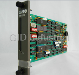
Bailey Controls IMRIO02 I/O Module - Remote I/O Slave Module
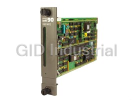
Bailey Controls INBIM-02 Interface Module INFI 90
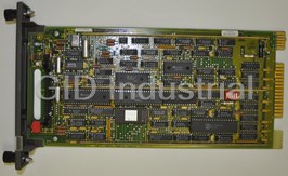
Bailey Controls INBTM-01 I/O Control - Bus Transfer Module Net 90
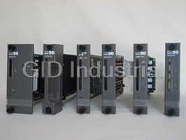
I/O Control System
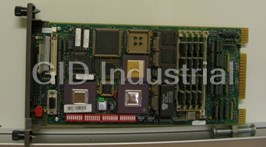
Bailey Controls INICT03A Systems-Infi-Net to Computer Transfer Module
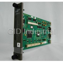
BAILEY CONTROLS INNIS21 LOOP CALIBRAT
Request a Quote

The quote request has been received
Close

Facing challenges or have inquiries? Feel free to contact us!
Call Us +1-469-283-2440
What they say about us
FANTASTIC RESOURCE
One of our top priorities is maintaining our business with precision, and we are constantly looking for affiliates that can help us achieve our goal. With the aid of GID Industrial, our obsolete product management has never been more efficient. They have been a great resource to our company, and have quickly become a go-to supplier on our list!
Bucher Emhart Glass
EXCELLENT SERVICE
With our strict fundamentals and high expectations, we were surprised when we came across GID Industrial and their competitive pricing. When we approached them with our issue, they were incredibly confident in being able to provide us with a seamless solution at the best price for us. GID Industrial quickly understood our needs and provided us with excellent service, as well as fully tested product to ensure what we received would be the right fit for our company.
Fuji
HARD TO FIND A BETTER PROVIDER
Our company provides services to aid in the manufacture of technological products, such as semiconductors and flat panel displays, and often searching for distributors of obsolete product we require can waste time and money. Finding GID Industrial proved to be a great asset to our company, with cost effective solutions and superior knowledge on all of their materials, it’d be hard to find a better provider of obsolete or hard to find products.
Applied Materials
CONSISTENTLY DELIVERS QUALITY SOLUTIONS
Over the years, the equipment used in our company becomes discontinued, but they’re still of great use to us and our customers. Once these products are no longer available through the manufacturer, finding a reliable, quick supplier is a necessity, and luckily for us, GID Industrial has provided the most trustworthy, quality solutions to our obsolete component needs.
Nidec Vamco
TERRIFIC RESOURCE
This company has been a terrific help to us (I work for Trican Well Service) in sourcing the Micron Ram Memory we needed for our Siemens computers. Great service! And great pricing! I know when the product is shipping and when it will arrive, all the way through the ordering process.
Trican Well Service
GO TO SOURCE
When I can't find an obsolete part, I first call GID and they'll come up with my parts every time. Great customer service and follow up as well. Scott emails me from time to time to touch base and see if we're having trouble finding something.....which is often with our 25 yr old equipment.
ConAgra Foods