

 Manufacturers
ARBOR TECHNOLOGY Em104-i313D/4S

Description
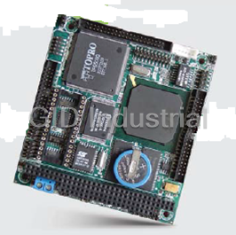
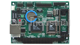
Arbor Em104-i313D/4S CPU Board - PC/104 386SX-40 Module with 4MB EDO RAM, 16-bit Digital I/O, 4 Serial Ports and DiskOnChip socket
Part Number
Em104-i313D/4S
Price
Request Quote
Manufacturer
ARBOR TECHNOLOGY
Lead Time
Request Quote
Category
PRODUCTS - E
Specifications
Bidirectional Parallel Port
supports SPP, EPP and ECP mode. BIOS enabled/disabled
BIOS
Y2K compliant AMI system BIOS
Board Dimensions
90 (L) x 96 (W) mm.
Board Weight
100 g
Bus Interface
PC/104
Chipset
ALi M6117
Realtek 8019AS single chip system
TP6508IQ (C&T 65545 optional)
CPU + Chipset
ALi M6117 is an implementation of an INTEL compatible 386SX-40 CPU, Real-time
Display
CRT and Flat Panel TTL-24 bit
DRAM Memory
4MB EDO DRAM onboard
Enhanced IDE
Supports one port and up to two drives Enhanced IDE devices of PIO mode 4, 44-pin connector
Expansion Slot
PC/104 Slot
Flash Disk
Supports Flash, EPROM and DOC 2000
Keyboard and Mouse Connectors
External PS/2 KB/Mouse port (6-pin) box wafer
Memory
1 MB onboard
Operating Temperature
0 ~ 60oC (32 to 140oF)
Panel Data Bus
24-bit
Power Requirements
single voltage +5 V @ 800 mA with 4 MB EDO installed
Processor
ALI M6117
Serial ports
2 high speed RS-232 ports, 2 high speed RS-232/485 ports (jumper selectable). Both with 16C550 UART and 16 byte FIFO. BIOS enabled/disabled. (COM3 and COM4 are optional.)
System Bus
16-bit ISA bus
Transfer mode
Full-duplex transfer mode
Watchdog Timer
generates either a RESET, NMI or an IRQ when your application loses control over the system. Normally the watchdog can trigger a user specified interrupt. The watchdog is configurable from 30.5 µs to 512 seconds (in 30.5 µs segments)
Datasheet

Extracted Text
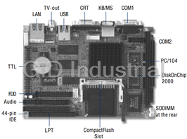
Em104-i313 PC-104 386SX-40 Module with Flat Panel / CRT SVGA, Digital I/O and LAN ALi M6117 compatible 386SX-40 CPU, ALi M6117 compatible 386SX-40 CPU, ALi M6117 compatible 386SX-40 CPU, ALi M6117 compatible 386SX-40 CPU, ALi M6117 compatible 386SX-40 CPU, 4MB EDO RAM Onboard, 4MB EDO RAM Onboard, 4MB EDO RAM Onboard, 4MB EDO RAM Onboard, 4MB EDO RAM Onboard, Supports DOC 2000, EIDE Interfaces, Supports DOC 2000, EIDE Interfaces, Supports DOC 2000, EIDE Interfaces, Supports DOC 2000, EIDE Interfaces, Supports DOC 2000, EIDE Interfaces, Realtek 8019AS 10BASE-T Realtek 8019AS 10BASE-T Realtek 8019AS 10BASE-T Realtek 8019AS 10BASE-T Realtek 8019AS 10BASE-T Table of Contents INFO Specifications ............................................................... 3 Ordering Codes............................................................. 4 OVERVIEW Board Image ................................................................ 5 Board Layout ................................................................ 6 HANDLING Jumper/Connector Quick Reference ........................... 7 Jumper/Connector Quick Reference ........................... 8 DOC, Flash and EPROM ............................................... 9 RS-232 & 485 selection On COM1 & COM2 .................10 COM2 RS-232/485 selection (J4).................................................. 10 RS-232/485 Mode on COM1 and COM2 ......................................... 10 Switches and Indicators ..............................................10 LCD Power Selection .................................................. 11 Power Connector .........................................................12 Fast Ethernet Connectors ............................................12 Enhanced IDE Connector ............................................13 Floppy Disk Drive Connector ......................................14 Parallel Port ...............................................................15 PS/2 Keyboard & Mouse .............................................16 16-bit General Purpose I/O .........................................16 LCD Connector ............................................................. 18 GPIO for ALi 6117 .........................................................19 7Configuration Registers ............................................................. 20 7Programming Guide ...................................................................... 21 WARRANTY Warranty ............................................................. 24 Specifications • CPU + Chipset : ALi M6117 is an implementation of an INTEL compatible 386SX-40 CPU, Real-time clock, a watchdog timer and ALi's M6117 chipset • BIOS : Y2K compliant AMI system BIOS • DRAM Memory: 4MB EDO DRAM onboard • Bus Interface : PC/104 • Enhanced IDE : Supports one port and up to two drives Enhanced IDE devices of PIO mode 4 44-pin connector • Flash Disk : Supports Flash, EPROM and DOC 2000 • Expansion Slot : PC/104 Slot • Keyboard and Mouse Connectors: External PS/2 KB/Mouse port (6-pin) box wafer • Watchdog Timer : generates either a RESET, NMI or an IRQ when your application loses control over the system. Normally the watchdog can trigger a user specified interrupt. The watchdog is configurable from 30.5 μs to 512 seconds (in 30.5 μs segments) High Speed Multi I/O High Speed Multi I/O High Speed Multi I/O High Speed Multi I/O High Speed Multi I/O • Chipset : ALi M6117 • Serial ports: 2 high speed RS-232 ports, 2 high speed RS-232/485 ports (jumper selectable). Both with 16C550 UART and 16 byte FIFO. BIOS enabled/disabled. (COM3 and COM4 are optional.) • Bidirectional Parallel Port : supports SPP, EPP and ECP mode. BIOS enabled/disabled Flat Panel Display Controller Flat Panel Display Controller Flat Panel Display Controller Flat Panel Display Controller Flat Panel Display Controller • Chipset : TP6508IQ (C&T 65545 optional) • Memory : 1 MB onboard • System Bus : 16-bit ISA bus • Panel Data Bus : 24-bit • Display : CRT and Flat Panel TTL-24 bit LAN Controller LAN Controller LAN Controller LAN Controller LAN Controller • Chipset : Realtek 8019AS single chip system • Transfer mode: Full-duplex transfer mode Environmental and Power Environmental and Power Environmental and Power Environmental and Power Environmental and Power • Power Requirements: single voltage +5 V @ 800 mA with 4 MB EDO installed • Board Dimensions : 90 (L) x 96 (W) mm. • Board Weight : 100 g o o • Operating Temperature: 0 ~ 60 C (32 to 140 F) Em104-i313 User's Manual Em104-i313 User's Manual Em104-i313 User's Manual Em104-i313 User's Manual Em104-i313 User's Manual 3 3 3 3 3 Warning PC/104 Modules and their components contain very delicate Inte- grated Circuits (IC). To protect the PC/104 Module and its compo- nents against damage form static electricity, you should always follow the following precautions when handling it : 1. Disconnect your PC/104 Module from the power source whenev- er you want to handle the module 2. Use a grounded wrist strap when handling the module. 3. Hold the module by the edges and try not to touch the IC chips, leads or circuitry 4. Place the module on a grounded antistatic pad or on the bag that came with the PC/104 Module when handling it. Ordering Codes Ordering Codes Ordering Codes Ordering Codes Ordering Codes Em104-i313DVL/4S PC/104 386SX-40 Module with 4MB EDO, Flat Panel/CRT SVGA, Fast Ethernet, Dis- kOnChip socket and 4 serial ports Em104-i313DVL PC/104 386SX-40 Module with 4MB EDO, Flat Panel/CRT SVGA, Fast Ethernet, Dis- kOnChip socket and 2 serial ports Em104-i313DV PC/104 386SX-40 Module with 4MB EDO, Flat Panel/CRT SVGA, 2 serial ports and DiskOnChip socket Em104-i313D/4S PC/104 386SX-40 Module with 4MB EDO, DiskOnChip socket and 4 serial ports 4 4 4 4 4 Em104-i313 User's Manual Em104-i313 User's Manual Em104-i313 User's Manual Em104-i313 User's Manual Em104-i313 User's Manual Board Image Em104-i313 User's Manual Em104-i313 User's Manual Em104-i313 User's Manual Em104-i313 User's Manual Em104-i313 User's Manual 5 5 5 5 5 Board Layout PWR1 IDE1 LAN1 CN2 J4 FDD1 LPT1 COM1~ GPIO1 COM4 EKM1 DOC 2000 LCD1 JV9 J3 Switches & Indicators VGA1 6 6 6 6 6 Em104-i313 User's Manual Em104-i313 User's Manual Em104-i313 User's Manual Em104-i313 User's Manual Em104-i313 User's Manual Jumper/Connector Quick Reference Jumpers Label Function J3 DOC, Flash and EPROM address selection J4 RS-232 & RS-485 Selection on COM1 and COM2 JV9 LCD Power Selection Em104-i313 User's Manual Em104-i313 User's Manual Em104-i313 User's Manual Em104-i313 User's Manual Em104-i313 User's Manual 7 7 7 7 7 Jumper/Connector Quick Reference Connectors Label Function PWR1 Power 4P Power Connector LAN1 LAN Connector EKM1 PS/2 Keyboard and PS/2 Mouse IDE1 Primary IDE Connector LPT1 Parallel Port LED1 LAN LED HLED1 HDD LED RES1 Reset SP1 External Speaker CN2 RS-485 Selection GPIO1 16-bit General Purpose I/O LCD1 LCD Connector 8 8 8 8 8 Em104-i313 User's Manual Em104-i313 User's Manual Em104-i313 User's Manual Em104-i313 User's Manual Em104-i313 User's Manual DOC, Flash and EPROM Jumper : J3 Type : Onboard 6-pin header Pin Status 1-2 3-4 5-6 ON ON ON DOC, D0000 OFF ON ON DOC, D8000 ON OFF ON FLASH, D0000 OFF OFF ON FLASH, D8000 OFF ON ON FLASH, D4000 OFF ON OFF EPROM, D0000 ON OFF OF EPROM, D8000 OFF OFF OFF All Open default setting DOC, D000 PWR1 IDE1 LAN1 CN2 J4 FDD1 LPT1 COM1~ GPIO1 COM4 EKM1 DOC 2000 LCD1 JV9 J3 Switches & Indicators VGA1 6 5 2 1 J 3 Em104-i313 User's Manual Em104-i313 User's Manual Em104-i313 User's Manual Em104-i313 User's Manual Em104-i313 User's Manual 9 9 9 9 9 RS-232 & 485 selection On COM1 & COM2 COM2 RS-232/485 selection (J4) COM2 RS-232/485 selection (J4) COM2 RS-232/485 selection (J4) COM2 RS-232/485 selection (J4) COM2 RS-232/485 selection (J4) The EM104-i313 offers two serial ports: COM1 and COM2. These ports let you connect to serial devices (mouse, printers, etc.), or to a communication network. The EM104-i313 serial ports can be configured by jumpers J4. Jumper : J4 Type : onboard 6-pin(2*3) header Pin Selection Status 1-3 RS232 on COM1 2-4 RS232 on COM2 3-5 RS485 on CN2 4-6 RS485 on CN2 RS-232/485 Mode on COM1 and COM2 RS-232/485 Mode on COM1 and COM2 RS-232/485 Mode on COM1 and COM2 RS-232/485 Mode on COM1 and COM2 RS-232/485 Mode on COM1 and COM2 The onboard COM1 and COM2 port can be configured to operate in RS-232 or RS-485 modes. RS-232 modes differ in the way RX/TX is being handled. Jumper J4 switches between RS-232C or RS-485 mode. All of the RS-232C/485 modes are available on COM1 and COM2. Pin RS-232C RS-485 1-3 : COM1 x (Default) 3-5 : x CN2 1,2 2-4 : COM2 x (Default) 4-6 : x CN2 3,4 4 2 - - + + PWR1 IDE1 LAN1 CN2 J4 3 1 CN2 FDD1 LPT1 CN2 Pin 1 RTX+ (COM1) 2 RTX- COM1~ 3 RTX+ (COM2) GPIO1 COM4 4 RTX- EKM1 6 5 DOC 2000 LCD1 2 1 J4 JV9 J3 Switches & Indicators VGA1 10 10 10 10 10 Em104-i313 User's Manual Em104-i313 User's Manual Em104-i313 User's Manual Em104-i313 User's Manual Em104-i313 User's Manual LCD Power Selection Jumper : JV9 Type : onboard 3-pin header The voltage of LCD panel could be selected by JV9 in 5V or 3.3V . Mode JV9 5V 1-2 3.3V 2-3 default setting +5V PWR1 IDE1 LAN1 CN2 J4 FDD1 LPT1 COM1~ GPIO1 COM4 EKM1 DOC 3 2000 LCD1 2 1 JV9 JV9 J3 Switches & Indicators VGA1 LINK ACTIVE + - + - - + 1 2 1 2 3 4 Switches and Indicators Connector Description RES1 Reset function HLED1 Hard Disk LED LED1 LAN LED SP1 Speaker Em104-i313 User's Manual Em104-i313 User's Manual Em104-i313 User's Manual Em104-i313 User's Manual Em104-i313 User's Manual 11 11 11 11 11 Reset HLED1 LAN LED SP1 Switch Power Connector Power Connector : PWR1 Connector : PWR1 Type : PWR1: onboard small 4P connector Pin Description Pin Description 1 +5V 2 GND 3 GND 4 +12V 210 1 9 PWR1 IDE1 LAN1 CN2 J4 FDD1 LPT1 COM1~ GPIO1 COM4 4 3 2 1 EKM1 DOC 2000 LCD1 JV9 J3 Switches & Indicators VGA1 Fast Ethernet Connectors Connector : LAN1 Type : Onboard 10-pin header Pin Description Pin Description 1 TX+ 2 TX- 3 RX+ 4 NC 5 NC 6 RX- 7NC 8 NC 9 GND 10 NC 12 12 12 12 12 Em104-i313 User's Manual Em104-i313 User's Manual Em104-i313 User's Manual Em104-i313 User's Manual Em104-i313 User's Manual Enhanced IDE Connector Connector : IDE1 Type : onboard 44-pin box headers Pin Description Pin Description 1 #RESET 2 GND 3D7 4 D8 5D6 6 D9 7 D5 8 D10 9 D4 10 D11 11 D3 12 D12 13 D2 14 D13 15 D1 16 D14 17 D0 18 D15 19 GND 20 NC/(Vcc) 21 REQ 22 GND 23 #IOW 24 GND 25 #IOR 26 GND 27 #IORDY 28 IDESEL 29 #DACK 30 GND 31 IRQ 32 NC 33 ADDR1 34 CBLID 35 ADDR0 36 ADDR2 37 #CS0 38 #CS1(#HD SELET1) 39 #ACT 40 GND 41 VCC 42 VCC 43 GND 44 NC 43 2 44 1 PWR1 IDE1 LAN1 CN2 J4 FDD1 LPT1 COM1~ GPIO1 COM4 EKM1 DOC 2000 LCD1 JV9 J3 Switches & Indicators VGA1 Em104-i313 User's Manual Em104-i313 User's Manual Em104-i313 User's Manual Em104-i313 User's Manual Em104-i313 User's Manual 13 13 13 13 13 Floppy Disk Drive Connector Connector : FDD1 Type : onboard 34-pin header Pin Description Pin Description 1 GND 2 DRIVE DENSITY SELECT 0 3 GND 4 DRIVE DENSITY SELECT 1 5 GND 6 NC 7 GND 8 #INDEX 9 GND 10 #MOTOR ENABLE A 11 GND 12 #DRIVER SELECT B 13 GND 14 #DRIVER SELECT A 15 GND 16 #MOTOR ENABLE B 17 GND 18 #DIRECTION 19 GND 20 #STEP 21 GND 22 #WRITE DATA 23 GND 24 #WRITE GATE 25 GND 26 #TRACK 0 27 GND 28 #WRITE PROTECT 29 GND 30 #READ DATA 31 GND 32 #HEAD SELECT 33 GND 34 #DISK CHANGE 34 2 1 33 PWR1 IDE1 LAN1 CN2 J4 FDD1 LPT1 COM1~ GPIO1 COM4 EKM1 DOC 2000 LCD1 JV9 J3 Switches & Indicators VGA1 14 14 14 14 14 Em104-i313 User's Manual Em104-i313 User's Manual Em104-i313 User's Manual Em104-i313 User's Manual Em104-i313 User's Manual Parallel Port Connector : LPT1 Type : onboard 26-pin header Pin Description Pin Description 1 #STROBE 14 #AUTO FEED 2 DATA0 15 #ERROR 3 DATA1 16 #INITIALIZE 4 DATA2 17 #SELECT INPUT 5 DATA3 18 GND 6 DATA4 19 GND 7 DATA5 20 GND 8 DATA6 21 GND 9 DATA7 22 GND 10 #ACKNOWLEDGE 23 GND 11 BUSY 24 GND 12 PAPER EMPTY 25 GND 13 SELECT 26 GND 26 14 1 13 PWR1 IDE1 LAN1 CN2 J4 FDD1 LPT1 COM1~ GPIO1 COM4 EKM1 DOC 2000 LCD1 JV9 J3 Switches & Indicators VGA1 Em104-i313 User's Manual Em104-i313 User's Manual Em104-i313 User's Manual Em104-i313 User's Manual Em104-i313 User's Manual 15 15 15 15 15 PS/2 Keyboard & Mouse Connector: EKM1 Type: Onboard 6-pin box header Pin Description Pin Description 1 KB-DATA 2 GND 3 MS-DATA 4 KB-CLK 5 +5V 6 MS-CLK Note: EKM1 supports PS/2 keyboard directly, and PS/2 mouse supported with the additional PS2 1-to-2 cable in the standard packing. PWR1 IDE1 LAN1 CN2 J4 FDD1 LPT1 COM1~ GPIO1 COM4 6 1 EK M 1 EKM1 DOC 2000 LCD1 JV9 J3 Switches & Indicators VGA1 16 16 16 16 16 Em104-i313 User's Manual Em104-i313 User's Manual Em104-i313 User's Manual Em104-i313 User's Manual Em104-i313 User's Manual 16-bit General Purpose I/O Connector : GPIO1 Type : Onboard 20-pin header Pin Description Pin Description 1 GROUND 2 VCC 3 GP0 4 GP8 5 GP1 6 GP9 7 GP2 8 GP10 9 GP3 10 GP11 11 GP4 12 GP12 13 GP5 14 GP13 15 GP6 16 GP14 17 GP7 18 GP15 19 VCC 20 GROUND PWR1 IDE1 LAN1 CN2 J4 20 19 FDD1 LPT1 2 COM1~ 1 GPIO1 COM4 EKM1 DOC 2000 LCD1 JV9 J3 Switches & Indicators VGA1 Em104-i313 User's Manual Em104-i313 User's Manual Em104-i313 User's Manual Em104-i313 User's Manual Em104-i313 User's Manual 17 17 17 17 17 LCD Connector Connector : LCD1 Type : onboard 44-pin header Pin Description Pin Description 1 Reserved for 12V 2 Reserved for 12V 3 GND 4 GND 5 LCDVDD 6 FPVDDEN 7 VBIAEN 8 GND 9B0 10 B1 11 B2 12 B3 13 B4 14 B5 15 B6 16 B7 17 G0 18 G1 19 G2 20 G3 21 G4 22 G5 23 G6 24 G7 25 R0 26 R1 27 R2 28 R3 29 R4 30 R5 31 R6 32 R7 33 GND 34 GND 35 FPSCLK 36 FP 37 DE 38 LP 39 GND 40 FPEN 41 GND 42 NC 43 VCC 44 VCC PWR1 IDE1 LAN1 CN2 J4 FDD1 LPT1 44 43 COM1~ GPIO1 COM4 EKM1 DOC 2000 LCD1 JV9 J3 Switches & Indicators VGA1 2 1 18 18 18 18 18 Em104-i313 User's Manual Em104-i313 User's Manual Em104-i313 User's Manual Em104-i313 User's Manual Em104-i313 User's Manual GPIO for ALi 6117 Em104-i313 use M6117 to supports GPIO (8 expandable GPOs & 8 expandable GPIs). During normal condition, pins XD[7:0] are data bus to peripheral devices. But during cold reset, XD[7:0] is an input pin and latched by internal register - index 68h; the pin ENPOWER is also active at this time to latch XD[7:0] at external 74LS373. Because there is no default value in index 68hand as to XD[7:0] without any pulling resistor. Designer has to connect externally pull-up or pull down resistors to XD[7-0] to initialize index 68h. The index 68h : D[7-0] are both readable and writable. If BIOS wants to change the external 74LS373 latch value. It should first set index 68h:D[7:0] a new value, then write any value to index 73h, that will generate an ENPOWER signal to update 74LS373 latch value. The index value in 68h will appear at XD[7:0] bus and ENPOWER will update the XD value to 74LS373. [Index 3Eh: The low byte GPI value. Default 00h Read only.] Em104-i313 User's Manual Em104-i313 User's Manual Em104-i313 User's Manual Em104-i313 User's Manual Em104-i313 User's Manual 19 19 19 19 19 1. Generate GPOs method 1. Generate GPOs method 1. Generate GPOs method 1. Generate GPOs method 1. Generate GPOs method (1) Use external 74373 input connect to SD bus. The latch enable pin connects to ENPOWER. (2) Set index 68h to desired GPO value. (3) Write index 73h. (4) Then data stored in index 68h will be sent to SD[7:0] and XD[7:0]. and ENPOWER will be active. (5) The value will be latched by 74373. 2. Generate GPIs method 2. Generate GPIs method 2. Generate GPIs method 2. Generate GPIs method 2. Generate GPIs method (1) Add external 74245, the input connects to GPIs, the output connects to ISA SD bus. The OE control connects to ISA REFRESHJ. (2) When REFRESHJ is active, the SD will become input and M6117 will use MEMRJ rising edge to latch the SD value. (3) Every 15us, the GPIs value will be updated. (4) It can read the GPIvalue through index 3Eh which store SD[7:0] value. 77Configuration Registers Configuration Registers 777Configuration Registers Configuration Registers Configuration Registers 1. Register Bit Definition: The details of M6117 configuration registers are described as follows : PORT 22H default 00H Bit Description 7~0 Index of Configuration register PORT 23H default 00H Bit Description 7~0 Data of Configuration register if unlock register unlocked. INDEX 3EH default 00H Bit Description 7~0 GPI signals. When REFRESHJ is active, the SD will become input and M6117D will use MEMRJ rising edge to latch the SD[7:0] to Bit 7~0. Read only INDEX 68H default 00H Bit Description 7~0 Power ON latched Power Control Initial status from XXD[7-0] D[7-0] : PWR[7-0] control pin status INDEX 73H default 00H Bit Description 7~0 Power Control status output command Write to this port will generate enpower pulse to update power control status. 20 20 20 20 20 Em104-i313 User's Manual Em104-i313 User's Manual Em104-i313 User's Manual Em104-i313 User's Manual Em104-i313 User's Manual 2. How to read/write to configuration registers 2. How to read/write to configuration registers 2. How to read/write to configuration registers 2. How to read/write to configuration registers 2. How to read/write to configuration registers The read/write configuration register is the first index to be processed. On board I/O port 22h is the index register and I/O port 23h is the data register. To read a configuration register, write the index value to I/O port 22h in advance, then read data from I/O port 23h. To write a configuration register, write the index value to I/O port 22h, then write data to I/O port 23h. For instance, if we want to read the data of configuration register which index is 10h, the steps are : 1) Write 10h (index) to I/O port 22h 2) Read data from I/O port 23h If we want to write data 55h to configuration register which index is 12h, then the steps are : 1) Write 12h (index) to I/O port 22h 2) Write data 55h to I/O port 23h *The steps of locking/unlocking the configuration registers : OUT 22h, 13h (Enable 13h) OUT 23h, C5h (Unlock) OUT 22h, XXh (XX = Configuration Index) OUT 23h, YYh (YY = Configuration data) OUT 22h, XXh OUT 23h, YYh (Configuration can be written repeatedly) : OUT 22h, 13h (Enable 13h) OUT 23h, 00h (Lock) 77777Programming Guide - Basic Procedure and Macro Definition Programming Guide - Basic Procedure and Macro Definition Programming Guide - Basic Procedure and Macro Definition Programming Guide - Basic Procedure and Macro Definition Programming Guide - Basic Procedure and Macro Definition a) Delay IO_Delay MACRO jcxz $+2 jcxz $+2 ENDM b) Unlock chipset configure registers¡@ Open_Chip MACRO mov al, 013h out 022h, al IO_Delay mov al, 0c5h out 023h, al IO_Delay ENDM Em104-i313 User's Manual Em104-i313 User's Manual Em104-i313 User's Manual Em104-i313 User's Manual Em104-i313 User's Manual 21 21 21 21 21 c) Lock chipset configure registers¡@ Close_Chip MACRO mov al, 013h out 022h, al IO_Delay mov al, 000h out 023h, al IO_Delay ENDM d) Write data to configure register ; INPUT : AH - INDEX# ; INPUT : AL - Data ; ACTION : Write the value of AL into the value of AH INDEX ; Interrupt controller and Stack are available Write_To_Chip PROCEDURE cli push ax Open_Chip pop ax out 022h, al IO_Delay xchg ah, al out 023h, al IO_Delay xchg ah, al push ax Close_Chip pop ax sti ret ENDP 22 22 22 22 22 Em104-i313 User's Manual Em104-i313 User's Manual Em104-i313 User's Manual Em104-i313 User's Manual Em104-i313 User's Manual e) Read data from configure register ; INPUT : AL - INDEX# ; OUTPUT : AL - Data ; ACTION : Read data from the value of AL INDEX ; Interrupt controller and Stack are available Read_From_Chip PROC cli push ax Open_Chip pop ax out 022h, al IO_Delay in al, 023h IO_Delay push ax Close_Chip pop ax sti ret ENDP Em104-i313 User's Manual Em104-i313 User's Manual Em104-i313 User's Manual Em104-i313 User's Manual Em104-i313 User's Manual 23 23 23 23 23 Warranty This product is warranted to be in good working order for a period of one year from the date of purchase. Should this product fail to be in good working order at any time during this period, we will, at our option, replace or repair it at no additional charge except as set forth in the following terms. This warranty does not apply to products damaged by misuse, modifications, accident or disaster. Vendor assumes no liability for any damages, lost profits, lost savings or any other inci- dental or consequential damage resulting from the use, misuse of, or inability to use this product. Vendor will not be liable for any claim made by any other related party. Return authorization must be obtained from the vendor before returned merchandise will be accepted. Authorization can be obtained by calling or faxing the vendor and request- ing a Return Merchandise Authorization (RMA) number. Returned goods should always be accompanied by a clear problem description. 24 24 24 24 24 Em104-i313 User's Manual Em104-i313 User's Manual Em104-i313 User's Manual Em104-i313 User's Manual Em104-i313 User's Manual
Frequently asked questions
What makes Elite.Parts unique?

What kind of warranty will the Em104-i313D/4S have?
Which carriers does Elite.Parts work with?
Will Elite.Parts sell to me even though I live outside the USA?
I have a preferred payment method. Will Elite.Parts accept it?
Why buy from GID?

Quality
We are industry veterans who take pride in our work

Protection
Avoid the dangers of risky trading in the gray market

Access
Our network of suppliers is ready and at your disposal

Savings
Maintain legacy systems to prevent costly downtime

Speed
Time is of the essence, and we are respectful of yours
Related Products
Arbor Em104-s415DVL CPU Board. STPC Elite 133Mhs 486 CPU board with LCD, CRT, Onboard 32MB SDRAM wit...
Arbor EmCORE-i315DL CPU Board - PC/104 386SX-40 Tiny CPU Module with 4MB EDO RAM, Realtek 8019AS LAN...
Arbor EmCORE-i3356 - Half-Sized Single-Board CPU | ALi M6117D/INTEL compatible 386SX-40ISA 386SX | S...
Arbor EmCORE-i741VL R1.0 CPU Board - 3.5 Form Factor Intel Pentium-M/Celeron-M up to 2.0GHz Mini-Boa...
3.5 Form Factor Ultra Low Voltage Celeron M 600MHz CPU Mini-Board w/ CRT / LCD / SVGA Display, TV-Ou...
Arbor EmCORE-n511 3.5” NS Geode GX1-300 Miniboard with Flat Panel / CRT, Audio and LAN
Request a Quote

The quote request has been received
Close

Facing challenges or have inquiries? Feel free to contact us!
Call Us +1-469-283-2440
What they say about us
FANTASTIC RESOURCE
One of our top priorities is maintaining our business with precision, and we are constantly looking for affiliates that can help us achieve our goal. With the aid of GID Industrial, our obsolete product management has never been more efficient. They have been a great resource to our company, and have quickly become a go-to supplier on our list!
Bucher Emhart Glass
EXCELLENT SERVICE
With our strict fundamentals and high expectations, we were surprised when we came across GID Industrial and their competitive pricing. When we approached them with our issue, they were incredibly confident in being able to provide us with a seamless solution at the best price for us. GID Industrial quickly understood our needs and provided us with excellent service, as well as fully tested product to ensure what we received would be the right fit for our company.
Fuji
HARD TO FIND A BETTER PROVIDER
Our company provides services to aid in the manufacture of technological products, such as semiconductors and flat panel displays, and often searching for distributors of obsolete product we require can waste time and money. Finding GID Industrial proved to be a great asset to our company, with cost effective solutions and superior knowledge on all of their materials, it’d be hard to find a better provider of obsolete or hard to find products.
Applied Materials
CONSISTENTLY DELIVERS QUALITY SOLUTIONS
Over the years, the equipment used in our company becomes discontinued, but they’re still of great use to us and our customers. Once these products are no longer available through the manufacturer, finding a reliable, quick supplier is a necessity, and luckily for us, GID Industrial has provided the most trustworthy, quality solutions to our obsolete component needs.
Nidec Vamco
TERRIFIC RESOURCE
This company has been a terrific help to us (I work for Trican Well Service) in sourcing the Micron Ram Memory we needed for our Siemens computers. Great service! And great pricing! I know when the product is shipping and when it will arrive, all the way through the ordering process.
Trican Well Service
GO TO SOURCE
When I can't find an obsolete part, I first call GID and they'll come up with my parts every time. Great customer service and follow up as well. Scott emails me from time to time to touch base and see if we're having trouble finding something.....which is often with our 25 yr old equipment.
ConAgra Foods