

 Manufacturers
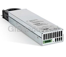
AGILENT / HP N6732B-761
Description
Agilent N6732B-761 DC Power Module. Output Disconnect Relay | 8 Volts | 6.25 Amps | 50-100 watts
Part Number
N6732B-761
Price
Request Quote
Manufacturer
AGILENT / HP
Lead Time
Request Quote
Category
PRODUCTS - N
Specifications
Load Regulation V/C
4 mV - 2 mA
Output 1,Volts/ Max. Current
8 V - 6.25 A
Output 2,Volts/ Max. Current
8 V - 12.5 A
Power Module
DC
Total Power
50 W - 100 W
Datasheet

Extracted Text
Agilent N6700 MPS Low-Profile Modular Power System Models: N6700B, N6701A, N6702A, N6710B, N6711A, N6712A, N6731B-36B, N6741B-46B, N6751-54A, N6761A-62A, N6773A-76A Product Overview New! Higher Power in Same Space Now Available– 300 Watt High-Performance DC Power Modules • Ideal for ATE systems in R&D, Design Validation, and Manufacturing • Small size: up to 4 outputs in 1U of rack space For Power • Flexible, modular system: Can mix and match power levels and performance Solutions levels to optimize investment in R&D – See back cover • Performance modules for critical test requirements • Value modules for basic DC power requirements • Fast command processing times to improve throughput • Connect via GPIB, LAN, or USB • Fully compliant to LXI Class C specification Agilent Technologies Small Size and N6700 System Features Flexibility for ATE Power supplies are a fundamental component of every test system in industries including aero- space and defense, consumer electronics, computers and peripherals, communications, semiconductor and automotive electronics. Today’s complex automatic test equipment (ATE) systems often require multiple power sources. Test Figure 1. Connectivity: GPIB, 10/100 Base-T Ethernet, and USB 2.0 all standard system designers are challenged to keep costs down by reducing rack space occupied by these DC power system optimized to can be mounted directly above multiple power supplies and to meet specific test requirements. or below it. (Requires rack continually increase test system Test system engineers can invest mount kit; see Ordering throughput. in high-performance outputs Information.) where speed and accuracy The Agilent N6700 Low-Profile are needed, or purchase basic Built-in Measurement Modular Power System (MPS) is performance outputs for simple of Voltage and Current a 1U (rack unit) high, multiple- DC power requirements. The N6700 modules come output programmable DC power standard with built-in supply system that enables test Small Size measurement of voltage and system integrators to optimize The Agilent N6700 MPS uses current to simplify wiring performance, power and price an advanced switching power and design of an ATE system. to match test needs. supply design that fits within 1U of rack space. It has side The Agilent N6700 MPS gives air vents (no top or bottom air test system designers the flexi- vents) so other instruments bility to mix and match from 20 different DC power modules to create a 1- to 4-channel 2 Protection Features Each N6700 module is protected Output on against over-voltage, over- current, and over-temperature. A fault condition in one V1 module can be detected within 10 microseconds by other mod- ules so that they can be quickly Module 1 shut down to avoid hazardous V2 conditions on your DUT. Delay 2 Connectivity V3 Module 2 The N6700 MPS comes standard with GPIB, USB 2.0, and 10/100 Base-T Ethernet LAN Module 3 interfaces. While GPIB is best Delay 3 suited for use with existing systems, Agilent offers USB and LAN to allow you to take advantage of the availability, Figure 2. Output Sequencing speed, and ease-of-use of common computer industry standard interfaces. The N6700 Control from any Browser For applications that require is fully compliant with the LXI The N6700 can be controlled more than four DC power Class C specification. via a standard web browser. modules to be sequenced, this The N6700 contains a web output sequencing can be Security server that provides web pages extended across multiple N6700 When used in systems running for monitor, control, and setup mainframes. By wiring together GPIB, the LAN and/or USB of the MPS. the I/O ports on the rear panel interfaces can be disabled of the mainframes, a pair of for extra security. Also, all Output Sequencing synchronization signals are sent non-volatile RAM data and Each DC power module can be between mainframes, allowing settings can be cleared from individually set to turn on or the output sequences of each the front panel. to turn off with a delay. By mainframe to be synchronized. adjusting the delay times and This capability is supported on then commanding the N6700 to N6700B, N6701A and N6702A turn on, you can set the N6700 mainframes. It is not supported modules to sequence on in a on N6700A mainframes. particular order. The same sequencing capability is avail- able to shut down the modules in a particular order. 3 Programmable Voltage Slew the N6700 system to treat power available from the main- For some applications, like up to 4 channels as a single, frame. In this case, the new inrush limiting or powering synchronized channel. Once power management features of rate-sensitive devices, it is configured, all functions the N6700 allow you to allocate necessary to slow down and (sourcing, measurements, mainframe power to the outputs control the speed of the power triggering, protection, and where it’s needed, achieving supply to maintain a specific status monitoring) behave maximum asset utilization and voltage slew rate. The N6700 as if there is 1 channel of flexibility. This feature provides provides programmable voltage up to 4 times the capacity the safety from unexpected slew rate, so that you can easily of a single channel, without and dangerous shutdowns that control the speed at which the writing a single line of code can occur with power systems output slews from one voltage to manage the interaction without power management to another. You can set the speed and synchronization of the when operated in a similar way. of a voltage change anywhere paralleled power supplies. from its maximum up/down For example, if your DUT programming speed to its slowest Virtual channel capability is requires 280 W on its main change of up to 10 seconds. available from the front panel input, and 10 W each on three Programmable voltage slew when operating the N6700 auxiliary inputs, you can con- is available from the front manually or via computer figure a system consisting of panel when operating the control. one 300 W DC module and N6700 manually or via com- three 100 W DC modules. Even puter control. Power Management Feature Allows though the sum of the module You Allocate Mainframe Power power is 600 W, you can still Series Operation Often, a DUT requires a single use the N6700B 400 W MPS To increase available voltage high power DC source and mainframe. Thanks to the and power, similarly rated several very low power DC power management feature, outputs can be operated sources. Since the DUT does you can allocate the full 300 W directly in series. not require full power to all to the 300 W module while you outputs, you may choose to allocate only 33 W to each of Easy Parallel Operation save money configuring a the 100 W modules. with Virtual Channels system where the sum of the To increase available output power modules installed in a power and current, identical mainframe exceeds the total outputs can be operated in parallel. To simplify parallel operation for applications requiring currents greater than any single output can provide, the N6700 offers virtual channels, a firmware- based feature that allows 4 Plug High Power Mainframes Triggering Output Disconnect and into Standard AC Sockets without The N6700 Low-Profile MPS Polarity Reversal Relays Dedicated High Current AC Circuits mainframe has hardware trigger Modules in the N6700 can When you first turn on the in/trigger out signals which be individually ordered with N6702A 1200 W MPS mainframe, permit the N6700 to be syn- optional Output Disconnect the mainframe automatically chronized with external events. Relays (option 761) or Output senses the power available from For example, a switch closure Disconnect/Polarity Reversal the AC line. If the AC line volt- in the fixture can trigger the Relays (option 760). See table on age is such that the resulting N6700 to apply voltage to the page 25 for option 760 and 761 current would exceed a standard DUT or take a measurement. availability. All relays are built AC outlet rating, the mainframe into the module, so no additional automatically scales back the Drivers wiring or rack space is needed available output power to pre- The N6700 comes with both to get the relay function. vent overloading the AC line. VXIplug&play drivers and The N6702A will limit the output IVI-COM drivers. LabView With option 761, Output power to 600 W allowing the drivers are available at NI.COM. Disconnect Relays, mechanical high power mainframe to be relays disconnect both the plus plugged into any standard out- Programming Language and minus side of the power let. This is very convenient for The N6700 supports SCPI supply, including the sense leads. initial bench checkout of the (Standard Commands for MPS system. It is also very Programmable Instruments). With option 760, Output convenient for test development, Disconnect/Polarity Reversal which is typically done on the Firmware Updates Relays, mechanical relays bench when DUT is not yet The N6700 firmware is stored in switch the leads on both the driven to full power. You can FLASH ROM and can be easily plus and the minus side of the also control this power reduction updated when new features power supply, including the by manually allocating less than become available. Firmware can sense leads, resulting in a volt- the full available mainframe be downloaded into the N6700 age polarity reversal at the power among the modules. As over GPIB, LAN, or USB using DUT. In addition to polarity a result, the N6702A will draw the supplied firmware update reversal, option 760 provides less power (and less current) utility program. Firmware the same output disconnect from the AC line. updates can be found at function as option 761. www.agilent.com/find/N6700firmware. Note: Output current is limited on some modules when option 760 Output Disconnect/Polarity Reversal Relays is installed. See the “Available options” tables at the bottom of page 25 and page 27 for more information about maximum current limita- tions with option 760. 5 Figure 3. Front panel with up to 4 channels displayed simultaneously (Picture shows 3 channels installed.) Figure 4. Rear panel (Picture shows 3 channels installed.) Front Panel Universal AC Input Rack Mount Kit In addition to full control over The N6700 has a universal input The N6700 is easily rack-mounted its three standard interfaces, the that operates from 100-240 Vac, using available option 908. N6700 has a full featured front 50/60/400 Hz. There are no This kit provides all the neces- panel to permit easy manual switches to set or fuses to sary hardware to rack mount operation for test prototyping, change when switching from one N6700 mainframe in only debugging, and troubleshooting one voltage standard to another. 1U of rack space. This rack when used in an ATE system. The AC input employs power mount kit includes front rack You can have confidence that factor correction. ears and rear supports which the N6700 is working properly take the place of standard rack because you can view the Quick Disconnects rails and/or slides. Note that settings and actual output Each power module has quick standard rack rails or slides values on all four outputs at disconnects for easy system are not needed and are not the same time. setup and maintenance. compatible with the N6700 because of its 1U size and Quieter Fans to Keep Noise Down airflow requirements. To reduce acoustic noise, the N6700 mainframes employ fan speed control. When operating at less than full output power, the cooling fans spin slower and generate less noise. Figure 5. Quick disconnects for power and sense leads 6 Choosing the right DC Power Modules to meet your ATE needs See detailed specifications on page 13 high-speed test extensions in general-purpose power supplies. The high-speed test extensions offer an oscilloscope-like digitizer that simplifies system configuration and increases measurement accuracy when viewing high-speed transient or pulse events within the device- under-test (DUT). In addition, autoranging output capabilities enable one power supply to do the job of several traditional N6750 Family power supplies. N6730/40/70 Family For applications where For basic DC applications the power supply plays a The Agilent N6730, N6740 and critical role N6770 families of DC power The Agilent N6750 family of modules provide programmable high-performance, autoranging voltage and current, measure- DC power modules provides ment and protection features low noise, high accuracy and at a very economical price, programming speeds that are making these modules suitable up to 10 to 50 times faster than to power the DUT or to provide other programmable power power for ATE system resources, supplies. In addition, Agilent such as fixture control. has, for the first time, included N6760 Family For applications where precision is required The Agilent N6760 family of precision DC power modules provides precise control and measurements in the milli- ampere and microampere region with the ability to simultaneously digitize voltage and current, and capture those measurements in an oscilloscope-like data buffer. Figure 6b. User re-configurable Figure 6a. The N6753A and the N6754A 300 W modular system high-performance autoranging DC power modules each occupy 2 module slots within the mainframe. All other modules occupy 1 module slot. 7 The N6750 and N6760 Families: Performance Modules for when the power supply is a critical part of your testing When your testing requires a Output Programming Speed Autoranging for Flexibility power supply to do more than When it comes to speed, the The N6750/60 gives test system just provide a constant DC N6750/60 achieves perfor- designers even more flexibility level, the N6750 family of High- mance unlike a typical DC by providing autoranging Performance, Autoranging DC power supply. Thanks to an outputs. This autoranging Power Modules and the N6760 active down-programming capability provides maximum family of Precision DC Power circuit to rapidly pull down output power at any output Modules are the perfect fit. the output when lowering the voltage up to 50 V. This allows These modules combine a fast module’s output voltage, the one power supply to do the output with flexible controls N6750/60 can rapidly program job of several power supplies and sophisticated measure- both up and down in voltage. because its operating range ments. The N6750/60 is more Changing voltage from 0 V covers low voltage, high cur- than a power supply; it is a to 50 V, or 50 V to 0 V, can rent as well as high voltage, stimulus/response instrument. be accomplished in less than low current operating points. 1.5 milliseconds. And for smaller To fit in 1U, the N6750/60 voltage changes, for example For example, the N6751A use an advanced switch-mode from 0 V to 5 V or 5 V to 0 V, High-Performance, Autoranging design that offers the low the programming speed is DC Module, rated at 50 V, 5 A, output noise and fast output less than 200 microseconds. and 50 W can provide full speed typically found on These output speeds allow the power at 10 V @ 5 A (=50 W), linear power supplies. N6750/60 to give maximum 20 V @ 2.5 A (= 50 W), 33.3 V @ system throughput when your 1.5 A (= 50 W), 50 V @ 1 A Low Noise Outputs test calls for frequent changes (= 50 W) or anywhere in Careful attention has been paid in power supply voltage settings. between. Therefore, this 50 W to this design to ensure low autoranging power supply, normal mode noise (ripple and peak-peak) as well as low com- mon mode noise. This switch- Voltage ing power supply outperforms most linear power supplies on Autoranging 50 W Output the market. 50 V 50 W Curve 10 V Current 0 1 A 5 A 8 due to its extended voltage and current range, can produce voltage and current combina- Voltage tions in the range of a 250 W non-autoranging power supply. The flexibility of autoranging is useful when the DUT operates over a wide range of voltages, when the ATE system needs to test a wide range of DUTs, or when margin is needed because the ATE power supply must be selected before final DUT power requirements are Time in seconds determined. See page 22 for a diagram Figure 7. High Speed Test Extensions LIST mode provides “power ARB” capability describing the details of the autoranging output character- istics of the N6750 and N6760 families of DC Power Modules. program the output to execute The result is an output that a LIST of voltage and current automatically changes according High-Speed Test Extensions setpoints. For each setpoint, a to the programmed list, just To make your testing go even dwell time can be specified and like an arbitrary waveform faster, the N6750/60 offer the power supply will stay (i.e., generator. High-Speed Test Extensions dwell) at that setpoint for the (HSTE). This enhancement to programmed dwell time value. * Note that the output response the N6750/60 DC Power Modules For each setpoint in the LIST, time is less than 5 millisec- extends the capabilities to you can have a different dwell onds per voltage change, include features similar to time from 0 to 262 seconds so steps of less than 5 mil- a built-in arbitrary waveform with 1 microsecond resolution.* liseconds will not achieve generator and a built-in Then, you can trigger the mod- their final output voltage oscilloscope. HSTE is optional ule to begin executing the list. value before moving on to on the N6750 DC Power Modules. The module will step thru the the next step. This is useful HSTE is standard on the N6760 list, staying at each setpoint when trying to create a DC Power Modules. for the programmed dwell time, smooth waveform. and then it will move on to the Through the LIST mode of next point. This speeds up HSTE, you can download up execution by removing the to 512 setpoints of voltage and current. In LIST mode, you can computer I/O from the process. 9 HSTE also provides an oscilloscope-like digitizer built into the power module to capture voltage and current measurements of up to 4096 points at up to 50,000 measurements per second. For applications such as design validation of battery powered digital devices, the ability to capture dynamic information about the current flowing into the DUT allows designers to better understand the current drain on DUT bat- teries and optimize DUT power management during normal DUT operation and in DUT standby mode. LIST. This is particularly useful power supplies provide preci- if you are trying to measure sion in the milliampere and The digitizer can also be current consumption during microampere regions. They are synchronized with changes in a rapidly changing voltage ideally suited for semiconductor the output. For example, the stimulus, such as current drawn and passive device testing, or digitizer can make measure- during a pulsed output voltage. where a precisely controlled ments in response to a trigger output and highly accurate, generated by a change in output Precision Low-level Performance precise measurements are voltage caused by LIST mode. The N6760 family of Precision needed during test. In this configuration, you can DC Power Modules additionally ensure that measurements are provide dual ranges on both made at the right moment programming and measure- during each step of an executing ment. In the low range, these 10 If you are using Agilent The N6730, N6740 and N6770 Families: Multiple-Output System Basic Modules when you just need a simple power supply DC Power Supplies Now Not all applications require high • Performance (programming Models performance power supplies. accuracy, measurement 6621A, 6622A, 6623A, When your budget is tight, accuracy, noise) suitable and when speed and accuracy for most common DC power 6624A, 6625A, 6626A, are a low consideration, the applications 6627A, 6628A, 6629A Agilent N6700 Low-Profile • Built-in optional output MPS supports basic DC power disconnect and polarity modules that provide an eco- If you would like to take advantage reversal relays, which break nomical solution. The N6730, of the size and speed of the N6700, both the power and the sense N6740 and N6770 families give leads, to simplify system wiring and need assistance in converting you clean, reliable DC power from Agilent 662x to the N6700, without advanced features. Use the N6730/40/70 in Place of please refer to “Application Fixed-output DC Power Supplies The Agilent N6730 family of Note 1467 – How to use the Many ATE systems have 50 W DC Power Modules, the complex fixtures that contain Agilent N6700 Series Modular N6740 family of 100 W DC Power indicator lights, relays or Power System to replace an Modules, and the N6770 family active circuits (like sensors, of 300 W DC Power Modules Agilent 662xA”. Look for literature triggers, amplifiers) to facilitate provide the following: part number 5989-0466EN testing of the DUT. These • Fully programmable circuits need DC power, too. at www.agilent.com/find/N6700 Constant Voltage/Constant One solution for powering Current DC Source these ATE system resources would be to purchase a fixed- • Remote sensing for output DC source. However, accurate control of output there are considerations when voltage when voltage drops integrating a fixed output in the leads are present DC source into an ATE system. • Built-in measurements of voltage and current • Protection (over-voltage over-current, and over- temperature) against damage to your DUT or to the power module 11 Factor Consideration When Using a Solution Using N6730/40/70 The table to the right illustrates Fixed-Output DC Power Supply DC Power Modules in N6700 MPS these points and how it may be easier, faster, and more economical to purchase an Control the You may want some limited control The N6730/40/70 is fully controllable N6730/40/70 programmable output over this DC source (on/off). over LAN, USB, GPIB DC Power Module in place of a fixed-output DC Power Supply. Monitor the You may want to be able to monitor The N6730/40/70 has built-in All the benefits of the output the voltage or current to ensure proper measurements of voltage and current, N6700 MPS at a low price operation, which would require wiring eliminating the need for wiring to a While the N6730/40/70 are to a system DMM. system DMM. economical solutions to basic DC power requirements, they are also part of the N6700 Mounting You will need to mount the power The N6730/40/70 are compact modules MPS. Therefore, while saving, the power supply in the ATE system. Finding a integrated into a 1U rack mountable supply you still have the benefits of: safe location can be a challenge. Some mainframe. There is no need to design system designers will build a “drawer” or build any custom mounting hardware. • Small size (true 1U) or “tray” for holding power supplies. • Mix-and-match with other However, this adds extra design time, N6700 DC Power Modules fabrication costs, installation costs, when you need performance and occupies rack space. along with basic DC outputs • Connectivity via LAN, USB, and GPIB Safety You may want to provide a safety The N6730/40/70 have hardware inputs interlock to this DC source. This for remote on/off that can be directly • Fast command processing would require control (on/off) and a connected to a safety interlock system. time of less than 1 ms means to detect the interlock condition. • Remote control over internet via standard web browser • Friendly front panel • Optional output disconnect and polarity reversal relays 12 Agilent N6751A/N6752A, N6753A, N6754A and N6761A/N6762A Performance Specifications Unless otherwise noted, specifications are warranted over the ambient temperature range of 0 to 55°C after a 30-minute warm-up period, with each module’s sense terminals externally jumpered directly to their respective output terminals (local sensing). N6751A / N6753A N6754A N6761A / N6752A N6762A DC Output Ratings Voltage 50 V 20 V 60 V 50 V Current (derated 1% per °C above 40°C) 5 A / 10 A 50 A 20 A 1.5 A / 3 A Power 50 W / 100 W 300 W 300 W 50 W / 100 W Output Ripple and Noise (PARD) (from 20 Hz – 20 MHz) CV peak-to-peak 4.5 mV 5 mV 6 mV 4.5 mV CV rms 350 µV 1 mV 1 mV 350 µV Load Effect (Regulation) (for any output load change, Voltage 2 mV 2 mV 2 mV 0.5 mV with a maximum load-lead Current (@ 0 - 7 V) 2 mA 12 mA 5 mA 30 µA drop of 1 V per lead) (@ 0 - 50 V) 2 mA 12 mA 5 mA 65 µA Source Effect (Regulation) Voltage 1 mV 0.5 mV 1.2 mV 0.5 mV Current 1 mA 5 mA 2 mA 30 µA Programming Accuracy (at 23°C ±5°C Voltage high range 0.06% + 19 mV 0.06% + 10 mV 0.06% + 25 mV 0.016% + 6 mV after 30 minute Voltage low range (≤ 5.5 V) N/A N/A N/A 0.016% + 1.5 mV warm-up. Applies Current high range 0.1% + 20 mA 0.10% + 30 mA 0.10% + 8 mA 0.04% + 200 µA from min. to max. Current low range (≤ 100 mA, @ 0 - 7 V) N/A N/A N/A 0.04% + 15 µA programming range) (≤ 100 mA, @ 0 - 50 V) N/A N/A N/A 0.04% + 55 µA Measurement Accuracy (at 23°C ±5°C) Voltage high range 0.05% + 20 mV 0.05% + 10 mV 0.05% + 25 mV 0.016% + 6 mV Voltage low range (≤ 5.5 V) N/A N/A N/A 0.016% + 1.5 mV Current high range 0.1% + 4 mA 0.10% + 30 mA 0.10% + 8 mA 0.04% + 160 µA NOTE 1 NOTE 2 Current low range (≤ 100 mA, @ 0 - 7 V) N/A N/A N/A 0.03% + 15 µA (≤ 100 mA, @ 0 - 50 V) N/A N/A N/A 0.03% + 55 µA Load Transient Recovery Time (time to recover to within the settling band following a load change) • from 60% to 100% and from 100% to 60% of full load for models N6751A & N6761A • from 50% to 100% and from 100% to 50% of full load for models N6752A-N6754A & N6762A. NOTE 2 NOTE 3 Voltage settling band ± 75 mV ± 30 mV ± 90 mV ± 75 mV Time < 100 µs < 100 µs < 100 µs < 100 µs 1 Applies when measuring 4096 data points (SENSe:SWEep:POINts = 4096). 2 Settling band is ±125 mV for Model N6752A when relay option 761 is installed. 3 Settling band is ±350 mV for Model N6754A when relay option 760 or 761 is installed. 13 Agilent N6751A/N6752A, N6753A, N6754A and N6761A/N6762A Supplemental Characteristics Supplemental characteristics are not warranted but are descriptions of performance determined either by design or type testing. All supplemental characteristics are typical unless otherwise noted. N6751A / N6753A N6754A N6761A / N6752A N6762A Programming Ranges Voltage high range 20 mV – 51 V 10 mV – 24.48 V 25 mV – 61.2 V 15 mV – 51 V Voltage low range (≤ 5.5 V) N/A N/A N/A 12 mV – 5.5 V Current high range 10 mA – 5.1 A/ 50 mA – 51 A 20 mA – 20.4 A 1 mA – 1.53 A/ 10 mA – 10.2 A 1 mA – 3.06 A NOTE 1 Current low range (≤ 0.1 A) N/A N/A N/A 0.1 mA – 0.1 A Programming Resolution NOTE 2 NOTE 2 NOTE 2 NOTE 3 Voltage high range 3.5 mV 1.5 mV 4.2 mV 880 µV Voltage low range (≤ 5.5 V) N/A N/A N/A 90 µV NOTE 4 NOTE 4 NOTE 4 Current high range 3.25 mA 16.3 mA 6.5 mA 60 µA Current low range (≤ 0.1 A) N/A N/A N/A 2 µA Measurement Resolution NOTE 5 NOTE 5 NOTE 5 NOTE 6 Voltage high range 1.8 mV 0.8 mV 2.2 mV 440 µV Voltage low range (≤ 5.5 V) N/A N/A N/A 44 µV Current high range 410 µA 2.05 mA 820 µA 30 µA Current low range (≤ 0.1 A) N/A N/A N/A 1 µA Programming Temperature Coefficient per °C Voltage high range 18 ppm + 160 µV 20 ppm + 20 µV 20 ppm + 50 µV 18 ppm + 140 µV Voltage low range (≤ 5.5 V) N/A N/A N/A 40 ppm + 70 µV Current high range 100 ppm + 45 µA 60 ppm + 500 µA 60 ppm + 200 µA 33 ppm + 10 µA Current low range (≤ 0.1 A) N/A N/A N/A 60 ppm + 1.5 µA Measurement Temperature Coefficient per °C Voltage high range 25 ppm + 35 µV 20 ppm + 20 µV 20 ppm + 50 µV 23 ppm + 40 µV Voltage low range (≤ 5.5 V) N/A N/A N/A 30 ppm + 40 µV Current high range 60 ppm + 3 µA 60 ppm + 30 µA 60 ppm + 12 µA 40 ppm + 0.3 µA Current low range (≤ 0.1 A) N/A N/A N/A 50 ppm + 0.3 µA Output Ripple and Noise (PARD) CC rms 2 mA 10 mA 4 mA 2 mA Common Mode Noise (from 20 Hz – 20 MHz; rms 500 µA 500 µA 750 µA 500 µA from either output to chassis) peak-to-peak < 2 mA 2 mA 3 mA < 2 mA Over-voltage Protection Accuracy 0.25% + 250 mV 0.25% ±150 mV 0.25% ±300 mV 0.25% + 250 mV Maximum setting 55 V 22 V 66 V 55 V Response time 50 µs from occurrence of over-voltage condition to start of output shutdown 1 If you are operating the unit below 255 µA in constant current mode, the output may become unregulated with the following load conditions: The load resistance is <175 mΩ and the load inductance is >20 µH. If this occurs, an UNRegulated flag will be generated and the output current may rise above the programmed value but will remain less than 255 µA. 2 Based on 14-bit DAC, with DAC range adjusted by software calibration 3 Based on 16-bit DAC, with DAC range adjusted by software calibration 4 Based on 12-bit DAC, with DAC range adjusted by software calibration 5 Based on 16-bit ADC (15 bits plus sign), with ADC range adjusted by software calibration 6 Based on 18-bit ADC (17 bits plus sign), with ADC range adjusted by software calibration 14 Agilent N6751A/N6752A, N6753A, N6754A and N6761A/N6762A Supplemental Characteristics (Continued) N6751A / N6753A N6754A N6761A / N6752A N6762A Maximum Up-programming Time with full resistive load (time from 10% to 90% For voltage change of 0 to 10 V 0 to 6 V 0 to 15 V 0 to 10 V of total voltage excursion) Up-programming time 0.2 ms 0.3 ms 0.3 ms 0.6 ms For voltage change of 0 to 50 V 0 to 20 V 0 to 60 V 0 to 50 V Up-programming time 1.5 ms 1.5 ms 2.0 ms 2.2 ms Maximum Up-programming Settling Time with full resistive load (time from start of voltage change For voltage change of 0 to 10 V 0 to 6 V 0 to 15 V 0 to 10 V to within 50 mV of final value) Up-programming settling time 0.5 ms 2.0 ms 2.0 ms 0.9 ms For voltage change of 0 to 50 V 0 to 20 V 0 to 60 V 0 to 50 V Up-programming settling time 4.0 ms 3.0 ms 4.0 ms 4.0 ms Maximum Down-programming Time with no load (time from start of voltage change For voltage change of 10 to 0 V 6 to 0 V 15 to 0 V 10 to 0 V to output voltage < 0.5 V) Down-programming time 0.3 ms 0.5 ms 0.6 ms 0.3 ms For voltage change of 50 to 0 V 20 to 0 V 60 to 0 V 50 to 0 V Down-programming time 1.3 ms 1.6 ms 2.0 ms 1.3 ms Maximum Down-programming Settling Time with no load (time from start of voltage For voltage change of 10 to 0 V 6 to 0 V 15 to 0 V 10 to 0 V change to output voltage Down-programming settling time 0.45 ms 0.7 ms 0.7 ms 0.45 ms within 50 mV of final value) For voltage change of 50 to 0 V 20 to 0 V 60 to 0 V 50 to 0 V Down-programming settling time 1.4 ms 3.0 ms 3.0 ms 1.4 ms Down-programming Time NOTE 1 with capacitive load NOTE 1 NOTE 2 NOTE 3 NOTE 1 (time from start of voltage change Capacitive load 1000 µF 4700 µF 680 µF 1000 µF to output voltage < 0.5 V) For voltage change of 10 to 0 V 6 to 0 V 15 to 0 V 10 to 0 V Down-programming time 0.3 ms 0.5 ms 0.6 ms 0.3 ms For voltage change of 50 to 0 V 20 to 0 V 60 to 0 V 50 to 0 V Down-programming time 1.3 ms 1.6 ms 2.0 ms 1.3 ms Down-programming Capability Continuous power 7 W 12.5 W 12.5 W 7 W Peak current 7 A 15 A 6 A 3.8 A Remote Sense Capability Outputs can maintain specifications with up to a 1-volt drop per load lead. Series and Parallel Operation Identically rated outputs can be operated directly in parallel or can be connected for straight series operation. Auto-series and auto-parallel operation is not available. 1 Modules can discharge a 1000 µF capacitor from 50 V to 0 V at a rate of 4 times/second. 2 Modules can discharge a 4700 µF capacitor from 20 V to 0 V at a rate of 4 times/second. 3 Modules can discharge a 680 µF capacitor from 60 V to 0 V at a rate of 4 times/second. 15 Agilent N6731B - N6736B and N6741B - N6746B Performance Specifications Unless otherwise noted, specifications are warranted over the ambient temperature range of 0 to 55°C after a 30-minute warm-up period, with each module’s sense terminals externally jumpered directly to their respective output terminals (local sensing) N6731B/ N6732B/ N6733B/ N6734B/ N6735B/ N6736B/ N6741B N6742B N6743B N6744B N6745B N6746B DC Output Ratings: Voltage 5 V 8 V 20 V 35 V 60 V 100 V NOTE 1 NOTE 3 Current 10 A / 20 A 6.25 A / 12.5 A 2.5 A / 5 A 1.5 A / 3 A 0.8 A / 1.6 A 0.5 A / 1 A Power 50 W / 100 W 50 W / 100 W 50 W / 100 W 52.5 W / 105 W 50 W / 100 W 50 W / 100 W Output Ripple and Noise (PARD) (from 20 Hz – 20 MHz) CV peak-to- peak 10 mV / 11 mV 12 mV 14 mV 15 mV 25 mV 30 mV CV rms 2 mV 2 mV 3 mV 5 mV 9 mV 18 mV Load Effect (Regulation) (with output change Voltage 5 mV 6 mV 9 mV 11 mV 13 mV / 16 mV 20 mV / 30 mV from no load to Current 2 mA 2 mA 2 mA 2 mA 2 mA 2 mA full load, up to a maximum load-lead drop of 1 V/lead) Source Effect (Regulation) Voltage 1 mV 2 mV 2 mV 4 mV 6 mV 10 mV Current 1 mA 1 mA 1 mA 1 mA 1 mA 1 mA Programming Accuracy (@ 23 °C ±5°C after Voltage 0.1% + 19 mV 0.1% + 19 mV 0.1% + 20 mV 0.1% + 35 mV 0.1% + 60 mV 0.1% + 100 mV 30 minute warm-up. Current 0.15% + 20 mA 0.15% + 20 mA 0.15% + 20 mA 0.15% + 20 mA 0.15% + 20 mA 0.15% + 10 mA Applies from minimum to maximum program- ming range) Measurement Accuracy (at 23°C ±5°C) Voltage 0.1% + 20 mV 0.1% + 20 mV 0.1% + 20 mV 0.1% + 35 mV 0.1% + 60 mV 0.1% + 100 mV Current 0.15% + 20 mA 0.15% + 10 mA 0.15% + 5 mA 0.15% + 4 mA 0.15% + 4 mA 0.15% + 2 mA Load Transient Recovery Time (time to recover to within the settling band following a load change from 50% to 100% and from 100% to 50% of full load.) NOTE 2 NOTE 2 Voltage settling band ±0.08 V / 0.1 V ±0.08 V / 0.1 V ± 0.2 V / 0.3 V ± 0.2 V / 0.3 V ± 0.4 V / 0.5 V ± 0.5 V / 1.0 V Time < 200 µs < 200 µs < 200 µs < 200 µs < 200 µs < 200 µs 1 Output current is derated 1% per °C above 40°C. 2 Settling band is ±0.10 V/0.125 V for 5 V and 8 V Models when relay options 760 and 761 are installed. 3 For N6742B, output current is limited to 10 A when option 760 Output Disconnect/Polarity Reversal Relays is installed. 16 Agilent N6731B - N6736B and N6741B - N6746B Supplemental Characteristics Supplemental characteristics are not warranted but are descriptions of performance determined either by design or type testing. All supplemental characteristics are typical unless otherwise noted. N6731B/ N6732B/ N6733B/ N6734B/ N6735B/ N6736B/ N6741B N6742B N6743B N6744B N6745B N6746B Programming Ranges Voltage 15 mV – 5 .1 V 15 mV – 8 .16 V 30 mV – 20.4 V 40 mV – 35.7 V 70 mV – 61.2 V 100 mV – 102 V Current 60 mA – 10.2 A/ 40 mA –6.375 A/ 10 mA – 2.55 A/ 5 mA – 1.53 A/ 2.5 mA – 0.85 A/ 1.5 mA – 0.51 A/ 60 mA – 20.4 A 40 mA – 12.75 A 10 mA – 5.1 A 5 mA – 3.06 A 2.5 mA – 1.7 A 1.5 mA – 1.02 A NOTE 1 Programming Resolution Voltage 3.5 mV 4 mV 7 mV 10 mV 18 mV 28 mV Current 7 mA 4 mA 3 mA 2 mA 1 mA 0.5 mA NOTE 2 Measurement Resolution Voltage 3 mV 4 mV 10 mV 18 mV 30 mV 50 mV Current 10 mA 7 mA 3 mA 2 mA 1 mA 0.5 mA Programming Temperature Coefficient per °C Voltage 0.005% + 0.1 mV 0.005% + 0.1 mV 0.005% + 0.2 mV 0.005% + 0.5 mV 0.005% + 0.5 mV 0.005% + 1 mV Current 0.005% + 1 mA 0.005% + 0.5 mA 0.005% + 0.1 mA 0.005% + 0.05 mA 0.005% + 0.02 mA 0.005% + 0.02 mA Measurement Temperature Coefficient per °C Voltage 0.01% + 0.1 mV 0.01% + 0.1 mV 0.01% + 0.2 mV 0.01% + 0.2 mV 0.01% + 0.5 mV 0.01% + 0.5 mV Current 0.01% + 1 mA 0.01% + 0.5 mA 0.01% + 0.1 mA 0.01% + 0.05 mA 0.01% + 0.02 mA 0.01% + 0.02 mA Output Ripple and Noise (PARD) CC rms 8 mA 4 mA 2 mA 2 mA 2 mA 2 mA Common Mode Noise (from 20 Hz – 20 MHz; from either output to chassis) rms 1 mA 1 mA 1 mA 1 mA 1 mA 1 mA peak-to-peak < 15 mA < 10 mA < 10 mA < 10 mA < 10 mA < 10 mA Over-voltage Protection Accuracy 0.25% + 50 mV 0.25% + 50 mV 0.25% + 75 mV 0.25% + 100 mV 0.25% + 200 mV 0.25% + 250 mV Accuracy w/opt 760 0.25% + 600 mV 0.25% + 600 mV 0.25% + 350 mV 0.25% + 250 mV 0.25% + 300 mV 0.25% + 300 mV Accuracy w/opt 761 0.25% + 600 mV 0.25% + 600 mV 0.25% + 350 mV 0.25% + 250 mV 0.25% + 300 mV 0.25% + 300 mV Maximum setting 7.5 V 10 V 22 V 38.5 V 66 V 110 V Response time 50 µs from occurrence of over-voltage condition to start of output shutdown Maximum Up-programming and Down-programming Time with full resistive load (time from 10% to 90% of total voltage excursion) Voltage setting from 0 V to 20 ms 20 ms 20 ms 20 ms 20 ms 20 ms full scale and full scale to 0 V Maximum Up-programming and Down-programming Settling Time with full resistive load (time from start of voltage change until voltage settles within 0.1% of the full-scale voltage of its final value) Voltage setting from 0 V to 100 ms 100 ms 100 ms 100 ms 100 ms 100 ms full scale and full scale to 0 V Remote Sense Capability Outputs can maintain specifications with up to a 1-volt drop per load lead. Series and Parallel Operation Identically rated outputs can be operated directly in parallel or can be connected for straight series operation. Auto-series and auto-parallel operation is not available. 1 Based on 12-bit DAC, with DAC range adjusted by software calibration 2 Based on 12-bit ADC (11 bits plus sign), with ADC range adjusted by software calibration 17 Agilent N6773A - N6776A Performance Specifications Unless otherwise noted, specifications are warranted over the ambient temperature range of 0 to 55°C after a 30-minute warm-up period, with each module's sense terminals externally jumpered directly to their respective output terminals (local sensing). N6773A N6774A N6775A N6776A DC Output Ratings Voltage 20 V 35 V 60 V 100 V NOTE 1 NOTE 3 Current 15 A 8.5 A 5 A 3 A Power 300 W 300 W 300 W 300 W Output Ripple and Noise (PARD) (from 20 Hz – 20 MHz) CV peak-to- peak 20 mV 22 mV 35 mV 45 mV CV rms 3 mV 5 mV 9 mV 18 mV Load Effect (Regulation) (with output change from no load Voltage 13 mV 16 mV 24 mV 45 mV to full load, up to a maximum Current 6 mA 6 mA 6 mA 6 mA load-lead drop of 1 V/lead) Source Effect (Regulation) Voltage 2 mV 4 mV 6 mV 10 mV Current 1 mA 1 mA 1 mA 1 mA Programming Accuracy: (@ 23°C ±5°C after 30 minute Voltage 0.1% + 20 mV 0.1% + 35 mV 0.1% + 60 mV 0.1% +100 mV warm-up. Applies from minimum Current 0.15% + 60 mA 0.15% + 60 mA 0.15% + 60 mA 0.15% + 30 mA to maximum programming range) Measurement Accuracy (at 23°C ±5°C) Voltage 0.1% + 20 mV 0.1% + 35 mV 0.1% + 60 mV 0.1% +100 mV Current 0.15% + 15 mA 0.15% + 12 mA 0.15% + 12 mA 0.15% + 6 mA Load Transient Recovery Time (time to recover to within the settling band following a load change from 50% to 100% and from 100% to 50% of full load.) NOTE 2 NOTE 2 Voltage settling band ± 0.3 V ± 0.3 V ± 0.5 V ± 1.0 V Time < 250 µs < 250 µs < 250 µs < 250 µs 1 Output current is derated 1% per °C above 40°C. 2 Settling band is ±0.35 V for 20 V and 35 V Models when relay options 760 and 761 are installed. 3 For N6773A, output current is limited to 10 A when option 760 Output Disconnect/Polarity Reversal Relays is installed. 18 Agilent N6773A - N6776A Supplemental Characteristics Supplemental characteristics are not warranted but are descriptions of performance determined either by design or type testing. All supplemental characteristics are typical unless otherwise noted N6773A N6774A N6775A N6776A Programming Ranges Voltage 30 mV – 20.4 V 40 mV – 35.7 V 70 mV – 61.2 V 100 mV – 102 V Current 30 mA – 15.3 A 15 mA – 8.67 A 7.5 mA – 5.1 A 4.5 mA – 3.06 A NOTE 1 Programming Resolution Voltage 7 mV 10 mV 18 mV 28 mV Current 9 mA 6 mA 3 mA 1.5 mA NOTE 2 Measurement Resolution Voltage 10 mV 18 mV 30 mV 50 mV Current 9 mA 6 mA 3 mA 1.5 mA Programming Temperature Coefficient per °C Voltage 0.01% + 0.2 mV 0.01% + 0.5 mV 0.01% + 0.5 mV 0.01% + 1 mV Current 0.01% + 0.5 mA 0.01% + 0.5 mA 0.01% + 0.1 mA 0.01% + 0.1 mA Measurement Temperature Coefficient per °C Voltage 0.01% + 0.2 mV 0.01% + 0.2 mV 0.01% + 0.5 mV 0.01% + 0.5 mV Current 0.01% + 0.5 mA 0.01% + 0.5 mA 0.01% + 0.05 mA 0.01% + 0.05 mA Output Ripple and Noise (PARD) CC rms 6 mA 6 mA 6 mA 6 mA Common Mode Noise (from 20 Hz – 20 MHz; from Rms 2 mA 2 mA 2 mA 2 mA either output to chassis) Peak-to- peak < 20 mA < 20 mA < 20 mA < 20 mA Over-voltage Protection Accuracy 0.25% +100 mV 0.25% + 130 mV 0.25% + 260 mV 0.25% + 650 mV Accuracy w/opt 760 0.25% + 700 mV 0.25% + 700 mV 0.25% + 400 mV 0.25% + 650 mV Accuracy w/opt 761 0.25% + 500 mV 0.25% + 350 mV 0.25% + 350 mV 0.25% + 650 mV Maximum setting 22 V 38.5 V 66 V 110 V Response time 50 µs from occurrence of over-voltage condition to start of output shutdown Maximum Up-programming and Down-programming Time with full resistive load (time from 10% to 90% of total voltage excursion) Voltage setting from 20 ms 20 ms 20 ms 20 ms 0 V to full scale and full scale to 0 V Maximum Up-programming and Down-programming Settling Time with full resistive load (time from start of voltage change until voltage settles within 0.1% of the full-scale voltage of its final value) Voltage setting from 100 ms 100 ms 100 ms 100 ms 0 V to full scale and full scale to 0 V Remote Sense Capability Outputs can maintain specifications with up to a 1-volt drop per load lead. Series and Parallel Operation Identically rated outputs can be operated directly in parallel or can be connected for straight series operation. Auto-series and auto-parallel operation is not available. 1 Based on 12-bit DAC, with DAC range adjusted by software calibration 2 Based on 12-bit ADC (11 bits plus sign), with ADC range adjusted by software calibration 19 Agilent N6700B, N6701A, N6702A MPS Mainframes N6700B, N6701A, N6702A Maximum Total Output Power (= Sum of Total Module Output N6700B 400 W when operating from 100 – 240 VAC input Power) N6701A 600 W when operating from 100 – 240 VAC input N6702A 1200 W when operating from 200 – 240 VAC input 600 W when operating from 100 – 120 VAC input Command Processing Time From receipt of command to start ≤ 1 ms of the output change Protection Response Characteristics INH input 5 µs from receipt of inhibit to start of shutdown Fault on coupled outputs < 10 µs (from receipt of fault to start of shutdown) Digital Control Characteristics Maximum voltage ratings 16.5 VDC/- 5 VDC between pins (pin 8 is internally connected to chassis ground). Pins 1 and 2 as FLT output Maximum low-level output voltage = 0.5 V @ 4 mA Maximum low-level sink current = 4 mA Typical high-level leakage current = 0.14 mA @ 16.5 VDC Pins 1 - 7 as digital/trigger outputs Maximum low-level output voltage = 0.5 V @ 4 mA; 1 V @ 50 mA; 1.75 V @ 100 mA (pin 8 = common) Maximum low-level sink current = 100 mA Typical high-level leakage current = 0.12 mA @ 16.5 VDC Pins 1 - 7 as digital/trigger inputs and Maximum low-level input voltage = 0.8 V pin 3 as INH input Minimum high-level input voltage = 2 V (pin 8 = common) Typical low-level current = 2 mA @ 0 V (internal 2.2 k pull-up) Typical high-level leakage current = 0.12 mA @ 16.5 VDC Interface Capabilities GPIB: SCPI - 1993, IEEE 488.2 compliant interface LXI Compliance Class C (applies to mainframes with firmware revision C.00.02 and up) USB 2.0 Requires Agilent IO Library version M.01.01 and up, or 14.0 and up 10/100 LAN Requires Agilent IO Library version L.01.01 and up, or 14.0 and up Built-in Web server Requires Internet Explorer 5+ or Netscape 6.2+ Environmental Conditions Operating environment Indoor use, installation category II (for AC input), pollution degree 2 Temperature range 0°C to 55°C (current is derated 1% per °C above 40°C ambient temperature) Relative humidity Up to 95% Altitude Up to 2000 meters Storage temperature -30°C to 70°C LED statement Any LEDs used in this product are Class 1 LEDs as per IEC 825-1 20 Agilent N6700B, N6701A, N6702A MPS Mainframes (Continued) N6700B, N6701A, N6702A Regulatory Compliance EMC Complies with the European EMC directive 89/336/EEC for Class A test and measurement products. Complies with the Australian standard and carries the C-Tick mark. This ISM device complies with Canadian ICES-001. Cet appareil ISM est conforme à la norme NMB-001 du Canada. Electrostatic discharges greater than 1 kV near the I/O connectors may cause the unit to reset and require operator intervention. Safety Complies with the European Low Voltage Directive 73/23/EEC and carries the CE-marking. This product also complies with the US and Canadian safety standards for test and measurement products. Acoustic Noise Declaration This statement is provided to Sound Pressure Lp < 70 dB(A), comply with the requirements At Operator Position, Normal Operation, According to EN 27779 (Type Test). * * * of the German Sound Emission Schalldruckpegel Lp <70 dB(A) Directive, from 18 January 1991. Am Arbeitsplatz, Normaler Betrieb, Nach EN 27779 (Typprüfung). * * * Output Terminal Isolation Maximum Rating No output terminal may be more than 240 VDC from any other terminal or chassis ground. AC Input Nominal Input Ratings 100 VAC – 240 VAC; 50/60 Hz/400 Hz Input Range 86 VAC – 264 VAC Power Consumption 1000 VA typical (N6700B mainframes) 1500 VA typical (N6701A mainframes) 3000 VA typical (N6702A mainframes) Fuse Internal fuse (not customer accessible) Dimensions Height 44.45 mm; 1.75 in. Width 432.5 mm; 17.03 in. Depth (including handles) 585.6 mm; 23.06 in. (N6700B/N6701A mainframes) 633.9 mm; 24.96 in. (N6702A mainframes) Weight N6700B with 4 installed modules Net: 12.73 kg; 28 lbs. N6701A with 4 installed modules Net: 11.82 kg; 26 lbs. N6702A with 4 installed modules Net: 14.09 kg; 31 lbs. Single-wide power module Net: 1.23 kg; 2.71 lbs Double-wide power module Net: 2.18 kg; 4.8 lbs 21 Power Module Autoranging Characteristic Option Characteristics Voltage Output Relays (Option 760/761) Autoranging 50 W Output • Type 50 V Double-pole, double-throw 50 W Curve • Location output & sense terminals 10 V Output Lists (Option 054): • Maximum number Current 0 1 A 5 A of steps = 512 • Maximum dwell time in seconds = 262 Voltage • Maximum list repetitions = Autoranging 100 W Output 256, or infinite 50 V 100 W Curve Digitized Measurements (Option 054) • Maximum measurement points = 4096 12 V • Maximum sample 8.5 V Current rate = 50 kHz 0 2 A 8.33 A 10 A Voltage Voltage N6753A Autoranging Precision Outputs 300 W Output 50 V 20 V 300 W Curve 33 V 6 V Current Current 0 1 A 1.5 A – 50 W output 0 15 A 50 A 2 A 3 A – 100 W output Voltage N6754A Autoranging 300 W Output 60 V 300 W Curve 15 V Current 0 5 A 20 A 22 Outline Diagram 549.7 mm 560.2 mm 21.64" 22.06" N6700B/ N6700B/ N6701A N6701A Top of Unit 598.0 mm 608.5 mm 23.96" 23.54" N6702A N6702A 25.4 mm 1.00" 432.5 mm 17.03" 44.45 mm 482.6 mm 19.00" 1.75" Agilent Technologies = Airflow 425.45 mm 16.75" 23 Right Side Ordering Information Mainframes The N6700 Modular Power System is available 2 ways: N6700B Low-Profile Modular Power System Mainframe, 400 W Holds 1 to 4 modules. Total available output power = 400 W. (1) You can order an N6700B, N6701A or N6702A mainframe N6701A Low-Profile Modular Power System Mainframe, 600 W Holds 1 to 4 modules. Total available output power = 600 W. and various modules as separate products. (See steps N6702A Low-Profile Modular Power System Mainframe, 1200 W below.) Each item will arrive Holds 1 to 4 modules. Total available output power = 1200 W. in a separate box such that you can assemble the system Available options to the N6700B, N6701A, N6702A Mainframes yourself when you need to. 908 Rack Mount Kit (2) You can order an N6710B, Required for rack mounting. Standard rack mount hardware will not work. N6711A or N6712A system, This N6700 Rack Mount Kit is also orderable separately as product N6709A which is a build-to-order system FLR Filler Panel Kit that is shipped as a fully Required when you have < 4 modules in a mainframe. Each filler panel kit contains 3 filler panels. assembled multiple-output This Filler Panel Kit is also orderable as product N6708A. power supply. (See pages 26 and 27 for N6710B, N6711A 0L1 Full documentation on CD-ROM and printed Users Guide and N6712A ordering 0B0 Full documentation on CD-ROM only; no printed documentation package information.) 900 Power Cord, United Kingdom, P/N 8120-1351 When ordering the N6700 MPS 901 Power Cord, Australia, New Zealand, P/N 8120-1369 as a mainframe and modules, 902 Power Cord, Europe, Korea, P/N 8120-1689 follow these steps: 903 Power Cord, USA, Canada, 120 V, P/N 8120-4383 Step 1: 904 Power Cord, USA, Canada, 240 V, P/N 8120-0698 Select which mainframe you want based on your power requirements. 906 Power Cord, Switzerland, P/N 8120-2104 912 Power Cord, Denmark, P/N 8120-2956 Step 2: Select the appropriate documenta- 917 Power Cord, South Africa, India, P/N 8120-4211 tion and line cord options. 918 Power Cord, Japan, 100 V, P/N 8120-5342 Note: For model N6702A, the maximum output power is limited to 600 W at 100 Vac. Step 3: To achieve full output power of 1200 W, you must use option 929 and operate at 200 Vac. Order 1 to 4 modules (see next page). If the sum of the power of the mod- 919 Power Cord, Israel, P/N 8120-6800 ules exceeds the available output 920 Power Cord, Argentina, P/N 8120-6869 power rating on the mainframe, see 921 Power Cord, Chile, P/N 8120-6980 page 4 for an explanation of Agilent’s power management capability. Note 922 Power Cord, China, P/N 8120-8376 that each mainframe has 4 module 927 Power Cord, Thailand, Brazil, P/N 8120-8871 slots to hold modules. Each module occupies one module slot, except for 929 Power Cord, Japan, 200 V, P/N 8121-1392 Note: This option is available only on model N6702A. the N6753A and the N6754A, which occupy 2 module slots per module. Step 4: Step 5: For proper operation, you must fill If you will be rack mounting your any empty module slots with filler N6700, you MUST order the Rack panels. When configuring a main- Mount Kit. frame with less than 4 filled module slots, you MUST order a Filler Panel Kit. Each kit contains 3 filler panels. Each filler panel fills one empty module slot. 24 Ordering Information Modules Modules Order 1 to 4 modules to be installed N6730 50 W N6731B 5 V, 10 A, 50 W DC Power Module in each N6700B, N6701A or N6702A DC Power Modules N6732B 8 V, 6.25 A, 50 W DC Power Module mainframe. (To order modules as N6733B 20 V, 2.5 A, 50 W DC Power Module part of the N6710B, N6711A or N6734B 35 V, 1.5 A, 50 W DC Power Module N6712A Build-to-order Systems, N6735B 60 V, 0.8 A, 50 W DC Power Module see page 27). If the sum of the N6736B 100 V, 0.5 A, 50 W DC Power Module power of the modules exceeds the available output power rating on N6740 100 W the mainframe, see page 4 for an DC Power Modules N6741B 5 V, 20 A, 100 W DC Power Module explanation of Agilent’s power N6742B 8 V, 12.5 A, 100 W DC Power Module management capability. N6743B 20 V, 5 A, 100 W DC Power Module N6744B 35 V, 3 A, 100 W DC Power Module You can individually specify each N6745B 60 V, 1.6 A, 100 W DC Power Module option for each module. For exam- N6746B 100 V, 1 A, 100 W DC Power Module ple, you can order one module with N6750 High-Performance, Option 761 Output Disconnect Autoranging DC Power N6751A 50 V, 5 A, 50 W High-Performance Relays while the remaining modules Modules Autoranging DC Power Module have no relay option. N6752A 50 V, 10 A, 100 W High-Performance Autoranging DC Power Module N6753A 20 V, 50 A, 300 W High-Performance As your needs change and you want Autoranging DC Power Module to change configuration or add more (occupies 2 module slots in the mainframe) modules to existing N6700A, N6700B, N6754A 60 V, 20 A, 300 W High-Performance N6701A or N6702A mainframes, Autoranging DC Power Module (occupies 2 module slots in the mainframe) use this ordering information to order the required modules. N6760 Precision DC Power Modules N6761A 50 V, 1.5 A, 50 W Precision DC Power Module N6762A 50 V, 3 A, 100 W Precision DC Power Module N6770 300 W DC Power Modules N6773A 20 V, 15 A, 300 W DC Power Module N6774A 35 V, 8.5 A, 300 W DC Power Module N6775A 60 V, 5 A, 300 W DC Power Module N6776A 100 V, 3 A, 300 W DC Power Module Available options to N6700 Modules N6731B-N6736B N6741B-N6746B N6751A-N6752A N6753A-N6754A N6761A-N6762A N6773A-N6776A 50 W DC 100 W DC High-Performance 300 W High- Precision DC 300 W DC Power Power Modules Power Modules Autoranging DC Performance Power Modules Modules Power Modules Autoranging DC Power Modules Output Disconnect Relays 761 761 761 761 761 761 Output Disconnect and Polarity Reversal Relays 760 760 (see note 1, 2) Not available 760 Not available 760 (see note 2) High Speed Test Extensions (HSTE) Not available Not available 054 054 Standard Not available Large Size FPGA Installed Not available, Not available, LGA (Required, Not available, Not available, Not available, not required not required see note 3) not required not required not required Commercial calibration with test results data UK6 UK6 UK6 UK6 UK6 UK6 ISO 17025 Cal certificate 1A7 1A7 1A7 1A7 1A7 1A7 1 Option 760 is not available on N6741B. 2 When Option 760 is installed in N6742B or N6773A, the maximum output current is limited to 10 A. 3 You must order Option LGA on N6751A and N6752A modules. Option LGA adds a large size FGPA to the module. Option LGA is required to support the Output Sequencing between mutliple mainframes. Option LGA will also allow for future expansion for additional firmware features. 25 Ordering Information N6700 Build-to-order Systems Build-to-order Systems To purchase an N6700 system, N6710B System Build-to-order Modular Power System, 400 W order an N6710B, N6711A, or Consists of 1 N6700B mainframe with total available power of 400 W. N6712A. These model numbers N6711A System Build-to-order Modular Power System, 600 W are build-to-order systems that Consists of 1 N6701A mainframe with total available power of 600 W. are shipped as a fully tested and assembled multiple-output power N6712A System Build-to-order Modular Power System, 1200 W supplies. Each system consists of Consists of 1 N6702A mainframe with total available power of 1200 W. one mainframe plus optionally 1 to 4 modules. Each mainframe has 4 module slots to hold mod- Available options to the N6710B, N6711A, N6712A Systems ules. Each module occupies one module slot, except for the N6753A 908 Rack Mount Kit and the N6754A, which occupy Required for rack mounting. Standard rack mount hardware will not work. 2 module slots per module. To This N6700 Rack Mount Kit is also orderable separately as product N6709A specify which modules you want 0L1 Full documentation on CD-ROM and printed Users Guide installed in the system, the mod- ules are ordered as options to the 0B0 Full documentation on CD-ROM only; no printed documentation package system model number. If you order 900 Power Cord, United Kingdom, P/N 8120-1351 less than 4 modules, the empty 901 Power Cord, Australia, New Zealand, P/N 8120-1369 slots will be automatically filled with blank filler panels. You must 902 Power Cord, Europe, Korea, P/N 8120-1689 order at least 1 module. 903 Power Cord, USA, Canada, 120 V, P/N 8120-4383 If the sum of the power of the 904 Power Cord, USA, Canada, 240 V, P/N 8120-0698 modules exceeds the available 906 Power Cord, Switzerland, P/N 8120-2104 output power rating on the mainframe, see page 4 for an 912 Power Cord, Denmark, P/N 8120-2956 explanation of Agilent’s power 917 Power Cord, South Africa, India, P/N 8120-4211 management capability. 918 Power Cord, Japan, 100 V, P/N 8120-5342 If you prefer to purchase a Note: For model N6712A, the maximum output power is limited to 600 W at 100 VAC. To achieve full ouput power of 1200 W, you must use option 929 mainframe and modules as and operate at 200 VAC. separate pieces, see page 24. 919 Power Cord, Israel, P/N 8120-6800 920 Power Cord, Argentina, P/N 8120-6869 921 Power Cord, Chile, P/N 8120-6980 922 Power Cord, China, P/N 8120-8376 927 Power Cord, Thailand, Brazil, P/N 8120-8871 929 Power Cord, Japan, 200 V, P/N 8121-1392 Note: This option is available only on model N6712A. 26 Ordering Information Modules as options to Module options for N6710B, N6711A and N6712A Systems N6710B, N6711A or N6712A N6730 50 W N6731B–ATO 5 V, 10 A, 50 W DC Power Module To order 1 to 4 module as options DC Power Modules N6732B–ATO 8 V, 6.25 A, 50 W DC Power Module to an N6710B, N6711A or N6712A, N6733B–ATO 20 V, 2.5 A, 50 W DC Power Module specify its model number, followed N6734B–ATO 35 V, 1.5 A, 50 W DC Power Module by “–ATO”. For example, to order an N6735B–ATO 60 V, 0.8 A, 50 W DC Power Module N6731B as an option to the N6710B, N6736B–ATO 100 V, 0.5 A, 50 W DC Power Module you would specify “N6731B–ATO” as the option. (To order modules as N6740 100 W N6741B–ATO 5 V, 20 A, 100 W DC Power Module DC Power Modules separate products, see page 25.) If N6742B–ATO 8 V, 12.5 A, 100 W DC Power Module the sum of the power of the mod- N6743B–ATO 20 V, 5 A, 100 W DC Power Module ules exceeds the available output N6744B–ATO 35 V, 3 A, 100 W DC Power Module power rating on the mainframe, N6745B–ATO 60 V, 1.6 A, 100 W DC Power Module see page 4 for an explanation N6746B–ATO 100 V, 1 A, 100 W DC Power Module of Agilent’s power management capability. N6750 High-Performance N6751A–ATO 50 V, 5 A, 50 W High-Performance Autoranging DC Autoranging DC Power Module Power Modules You can individually specify each N6752A–ATO 50 V, 10 A, 100 W High-Performance Autoranging DC Power Module option for each module. For exam- N6753A-ATO 20 V, 50 A, 300 W High-Performance ple, you can order one module Autoranging DC Power Module with Option 761 Output Disconnect (occupies 2 module slots in the mainframe) Relays while the remaining modules N6754A-ATO 60 V, 20 A, 300 W High-Performance Autoranging DC Power Module have no relay option. (occupies 2 module slots in the mainframe) N6760 Precision N6761A–ATO 50 V, 1.5 A, 50 W Precision DC Power Module DC Power Modules N6762A–ATO 50 V, 3 A, 100 W Precision DC Power Module N6770 300 W N6773A–ATO 20 V, 15 A, 300 W DC Power Module DC Power Modules N6774A–ATO 35 V, 8.5 A, 300 W DC Power Module N6775A–ATO 60 V, 5 A, 300 W DC Power Module N6776A–ATO 100 V, 3 A, 300 W DC Power Module Available options to N6700 Modules N6731B-ATO N6741B-ATO N6751A-ATO N6753A-ATO N6761A-ATO N6773A-ATO to N6736B-ATO to N6746B-ATO to N6752A-ATO to N6754A-ATO to N6762A-ATO to N6776A-ATO 50 W DC Power 100 W DC Power High-Performance 300 W High- Precision DC 300 W DC Power Modules Modules Autoranging DC Performance Power Modules Modules Power Modules Autoranging DC Power Modules Output Disconnect Relays 761 761 761 761 761 761 Output Disconnect and Polarity Reversal Relays 760 760 (see note 1, 2) Not available 760 Not available 760 (see note 2) High Speed Test Extensions (HSTE) Not available Not available 054 054 Standard Not available Large Size FPGA Installed Not available, Not available, LGA (Required, Not available, Not available, Not available, not required not required see note 3) not required not required not required Commercial calibration with test results data UK6 UK6 UK6 UK6 UK6 UK6 ISO 17025 Cal certificate 1A7 1A7 1A7 1A7 1A7 1A7 1 Option 760 is not available on N6741B-ATO. 2 When Option 760 is installed in N6742B-ATO or N6773A-ATO, the maximum output current is limited to 10 A. 3 You must order Option LGA on N6751A and N6752A modules. Option LGA adds a large size FGPA to the module. Option LGA is required to support the Output Sequencing between mutliple mainframes. Option LGA will also allow for future expansion for additional firmware features. 27 Compatibility and Upgrade Information Agilent recommends that you keep your N6700 system up to date with the latest firmware available at www.agilent.com/find/N6700firmware. You have with firmware and with modules If you want to … … here is what you need to do N6700A or Any version Any combination of modules Add or change modules to Capability is available with your N6710A of firmware with model number N673xA, mix-and-match any combination current version of hardware and starting with A N674xA, N6751A, N6752A, of modules with model numbers firmware. No upgrade required. (example: A.00.00) or N676xA N673xA, N674xA, N675xA or N676xA Add or change modules to Install firmware version C.02.00 mix-and-match any combination or greater available at of modules with model numbers www.agilent.com/find/N6700firmware N673xA, N673xB, N674xA, N674xB, N675xA, N676xA or N677xA including new modules N6753A and N6754A Add new capabilities Install firmware version C.02.00 • Virtual channel capability or greater available at for paralleling www.agilent.com/find/N6700firmware • Programmable voltage slew capability • Power management capability • Output sequencing across mainframes N6700A or Any version of Any combination of modules Add or change modules to Capability is available with your N6710A firmware B.00.34 with model number N673xA, mix-and-match any combination current version of hardware and or earlier N673xB, N674xA, N674xB, of modules with model numbers firmware. No upgrade required. N6700B or N6751A, N6752A, or N676xA N673xA, N673xB, N674xA, N6710B N674xB, N675xA or N676xA Add or change modules to Install firmware version C.02.00 mix-and-match any combination or greater available at of modules with model numbers www.agilent.com/find/N6700firmware N673xA, N673xB, N674xA, N674xB, N675xA, N676xA or N677xA including new modules N6753A and N6754A Add new capabilities Install firmware version C.02.00 • Power management capability or greater available at • Output sequencing across www.agilent.com/find/N6700firmware mainframes N6700A or C.02.00 or C.01.04 Any combination of modules Add or change modules to Capability is available with your N6710A with model number N673xA, mix-and-match any combination current version of hardware and N673xB, N674xA, N674xB, of modules with model numbers firmware. No upgrade required. N6700B or N675xA, N676xA, or N677xA N673xA, N673xB, N674xA, N674xB, N6710B N675xA, N676xA or N677xA Add new capabilities Capability is available with your N6701A or • Power management capability current version of hardware and N6711A • Output sequencing across firmware. No upgrade required. mainframes N6702A or N6712A Add new modules Install firmware version C.02.00 N6753A and N6754A or greater available at www.agilent.com/find/N6700firmware 28 Compatibility and Upgrade Information (Continued) Agilent recommends that you keep your N6700 system up to date with the latest firmware available at www.agilent.com/find/N6700firmware. You have with firmware and with modules If you want to … … here is what you need to do N6721A Any version Any combination of modules Add more modules with model Capability is available with your through of firmware with model number N675xA numbers N675xA or N676xA current version of hardware and N6729A starting with A or N676xA firmware. No upgrade required. (example: A.00.00) Add or change modules to Install firmware version C.02.00 mix-and-match any combination or greater available at of modules with model numbers www.agilent.com/find/N6700firmware N673xA, N673xB, N674xA, N674xB, N675xA, N676xA or N677xA (see note 1 below) Add new capabilities Install firmware version C.02.00 • Virtual channel capability or greater available at for paralleling www.agilent.com/find/N6700firmware • Programmable voltage slew capability • Power management capability • Output sequencing across mainframes (see note 2 below) Notes: 1 If you add modules with model numbers N673xA, N673xB, N674xA, N674xB, N6753A, N6754A or N677xA, you will not be able to access the Agilent 662x command set capability of your N672xA for any installed modules. Only SCPI commands will be accepted. 2 These features are not available in the Agilent 662x command set. You must use SCPI commands to access these new programmable features. Compatibility with older models Older A version Equivalent configuration with If you previously purchased Agilent Model model number latest N6700 series models an Agilent 662xA or N672xA, and you want to make another 6621A N6721A N6700B + 2 x N6752A purchase, use the table at right 6622A N6722A N6700B + 2 x N6752A to find the equivalent configura- 6623A N6723A N6700B + 2 x N6751A tion of N6700B Low-Profile 1 x N6752A Modular Power System Mainframe and DC Power Modules. 6624A N6724A N6700B + 4 x N6751A 6625A N6725A N6700B + 1 x N6761A 1 x N6762A 6626A N6726A N6700B + 2 x N6761A 2 x N6762A 6627A N6727A N6700B + 4 x N6751A 6628A N6728A N6700B + 2 x N6762A 6629A N6729A N6700B + 4 x N6762A 29 Agilent Email Updates Remove all doubt www.agilent.com www.agilent.com/find/emailupdates Our repair and calibration services For more information on Agilent Technologies’ Get the latest information on the products, applications or services, please will get your equipment back to you, products and applications you select. contact your local Agilent office. The complete performing like new, when prom- list is available at: ised. You will get full value out of Agilent Direct your Agilent equipment through- www.agilent.com/find/contactus out its lifetime. Your equipment www.agilent.com/find/agilentdirect Quickly choose and use your test will be serviced by Agilent-trained Americas equipment solutions with confidence. technicians using the latest factory Canada (877) 894-4414 calibration procedures, automated Latin America 305 269 7500 Agilent repair diagnostics and genuine parts. United States (800) 829-4444 Open You will always have the utmost www.agilent.com/find/open confidence in your measurements. Asia Pacific Agilent Open simplifies the process Australia 1 800 629 485 of connecting and programming Agilent offers a wide range of ad- test systems to help engineers China 800 810 0189 ditional expert test and measure- design, validate and manufacture Hong Kong 800 938 693 ment services for your equipment, electronic products. Agilent offers India 1 800 112 929 including initial start-up assistance open connectivity for a broad range Japan 81 426 56 7832 onsite education and training, as well of system-ready instruments, open Korea 080 769 0800 as design, system integration, and industry software, PC-standard I/O Malaysia 1 800 888 848 project management. and global support, which are Singapore 1 800 375 8100 combined to more easily integrate Taiwan 0800 047 866 test system development. For more information on repair and Thailand 1 800 226 008 calibration services, go to: Europe www.agilent.com/find/removealldoubt www.lxistandard.org Austria 0820 87 44 11 LXI is the LAN-based successor to Belgium 32 (0) 2 404 93 40 GPIB, providing faster, more efficient Denmark 45 70 13 15 15 connectivity. Agilent is a founding Finland 358 (0) 10 855 2100 member of the LXI consortium. France 0825 010 700 Germany 01805 24 6333* Need a power solution for R&D bench work? *0.14 /minute The new Agilent N6705A DC Power Analyzer saves time Ireland 1890 924 204 Italy 39 02 92 60 8484 Netherlands 31 (0) 20 547 2111 • Provides unrivaled productivity Spain 34 (91) 631 3300 gains for sourcing and measuring Sweden 0200-88 22 55 DC voltage and current into your Switzerland (French) 41 (21) 8113811(Opt 2) DUT by integrating up to 4 advanced Switzerland (German) 0800 80 53 53 (Opt 1) power supplies with DMM, Scope, Arb, United Kingdom 44 (0) 118 9276201 and Datalogger features. Other European Countries: • Eliminates the need to gather multiple pieces of equipment, www.agilent.com/find/contactus create complex test setups including transducers (such as current Revised: May 7, 2007 probes and shunts) to measure current into your DUT. • Eliminates the need to develop and debug programs to control a Product specifications and descriptions in this collection of instruments and take useful measurements because all document subject to change without notice. the functions and measurements are available at the front panel. For the latest and complete product information on the Agilent N6700, go to • Modular system: Uses the same DC Power Modules at the N6700 http://www.agilent.com/find/N6700. Low-Profile Modular Power System © Agilent Technologies, Inc. 2007 Complete specifications can be found in the N6705A DC Power Analyzer Printed in USA, June 15, 2007 Data Sheet, publication 5989-6319EN 5989-1411EN For more information go to www.agilent.com/find/dcpoweranalyzer Agilent Technologies
Frequently asked questions
What makes Elite.Parts unique?

What kind of warranty will the N6732B-761 have?
Which carriers does Elite.Parts work with?
Will Elite.Parts sell to me even though I live outside the USA?
I have a preferred payment method. Will Elite.Parts accept it?
Why buy from GID?

Quality
We are industry veterans who take pride in our work

Protection
Avoid the dangers of risky trading in the gray market

Access
Our network of suppliers is ready and at your disposal

Savings
Maintain legacy systems to prevent costly downtime

Speed
Time is of the essence, and we are respectful of yours
Related Products

N1025
Agilent N1045A Plug-in Module
Agilent N1455-10002 WIN98 Certificate of Authenticity
Agilent N2864A Rack Mount - Rack mount kit for Agilent 3000 Series oscilloscopes
Agilent N2X Next Generation 10Gb/s Test Cards
Agilent N5221A Microwave Network Analyzer | 10 MHz to 13.5 GHz
Request a Quote

The quote request has been received
Close

Facing challenges or have inquiries? Feel free to contact us!
Call Us +1-469-283-2440
What they say about us
FANTASTIC RESOURCE
One of our top priorities is maintaining our business with precision, and we are constantly looking for affiliates that can help us achieve our goal. With the aid of GID Industrial, our obsolete product management has never been more efficient. They have been a great resource to our company, and have quickly become a go-to supplier on our list!
Bucher Emhart Glass
EXCELLENT SERVICE
With our strict fundamentals and high expectations, we were surprised when we came across GID Industrial and their competitive pricing. When we approached them with our issue, they were incredibly confident in being able to provide us with a seamless solution at the best price for us. GID Industrial quickly understood our needs and provided us with excellent service, as well as fully tested product to ensure what we received would be the right fit for our company.
Fuji
HARD TO FIND A BETTER PROVIDER
Our company provides services to aid in the manufacture of technological products, such as semiconductors and flat panel displays, and often searching for distributors of obsolete product we require can waste time and money. Finding GID Industrial proved to be a great asset to our company, with cost effective solutions and superior knowledge on all of their materials, it’d be hard to find a better provider of obsolete or hard to find products.
Applied Materials
CONSISTENTLY DELIVERS QUALITY SOLUTIONS
Over the years, the equipment used in our company becomes discontinued, but they’re still of great use to us and our customers. Once these products are no longer available through the manufacturer, finding a reliable, quick supplier is a necessity, and luckily for us, GID Industrial has provided the most trustworthy, quality solutions to our obsolete component needs.
Nidec Vamco
TERRIFIC RESOURCE
This company has been a terrific help to us (I work for Trican Well Service) in sourcing the Micron Ram Memory we needed for our Siemens computers. Great service! And great pricing! I know when the product is shipping and when it will arrive, all the way through the ordering process.
Trican Well Service
GO TO SOURCE
When I can't find an obsolete part, I first call GID and they'll come up with my parts every time. Great customer service and follow up as well. Scott emails me from time to time to touch base and see if we're having trouble finding something.....which is often with our 25 yr old equipment.
ConAgra Foods