

 Manufacturers
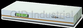
AEGIS MICRO VP-300
Description
VP-300 remote video web camera server supports full motion live video footage with its corresponding audio through the Internet, Intranet, or direct dial-up modem connection via common telephone lines. Up to four video cameras can be hooked up to this 19" rack mountable unit to deliver real-time full-motion A/V transmission to anywhere in the world through a desktop PC, workstation, or laptop. All that is needed is an Internet browser and our proprietary software. This system also allows users to record digital video footage continuously onto their computer hard drive. Attached video cameras can be remotely controlled to swivel and zoom in and out, and the unit can be triggered to initiate certain events through our specialized call-back feature by utilizing a telephone connection. The VP-300 is completely Plug & Play compatible to get you up and running as soon as possible without the need for ongoing maintenance or custom hardware/software configurations
Part Number
VP-300
Price
Request Quote
Manufacturer
AEGIS MICRO
Lead Time
Request Quote
Category
PRODUCTS - V
Datasheet

Extracted Text
Notice CE Warning The information in this manual was current when published. The manufacturer This is a Class A product, in a domestic environment this product may cause reserves the right to revise and improve its products. radio interference in which case the user may be required to take adequate All specifications are therefore subject to change without notice. measures. FCC Warning Trademarks This device complies with Part 15 of the FCC Rules. Operation is subject to the VPON ® is a registered trademark of Formosa Industrial Computing Inc. following two conditions (1) this device may not cause harmful interference, Microsoft, Windows, Internet Explorer ® are registered trademarks of Microsoft and (2) this device must accept any interference received, including interference Corporation. Netscape, Navigator, Communicator ® are registered trademarks of that may cause undesired operation. Netscape Corporation. Other brand and product names referred to in this manual are trademarks or registered trademarks of their respective holders. Trademarked names are used throughout this manual. Rather than place a symbol at each occurrence, trademarked names are designated with initial capitalization. Inclusion or exclusion is not a judgment on the validity or legal status of the term. Important information Warning Before proceeding, please read and observe all instructions and warnings contained To reduce risk of electric shock, do not remove cover. No user service-able parts in this manual. Retain this manual with the original bill of sale for future reference and, inside. Refer servicing to qualified service personnel. if necessary, warranty service. Do not expose this appliance to rain or moisture. When unpacking your VPON unit, check for missing or damaged items. If any item is Do not install this product in hazardous areas where highly combustible or missing, or if damage is evident, DO NOT INSTALL OR OPERATE THIS explosive products are stored or used. PRODUCT. Contact your dealer or us for assistance. The lightning flash/arrowhead symbol, within and equilateral triangle, alerts the user to the presence of a shock hazard within the product’s enclosure. i ii Table of Content 3.4 Audio Functions -------------------------------------------------------------- 35 3.5 Remote Camera Control------------------------------------------------------ 36 Chapter 1: Introduction 3.5.1 Remote Camera Control Using PTZ Cameras------------------- 37 1.1 Main Features--------------------------------------------------------------------1 1.2 System Requirements ----------------------------------------------------------2 3.5.2 Remote Camera Control Using VP-201 and VP-202 ----------- 38 1.3 Quick Installation Procedure -------------------------------------------------3 3.5.3 Operation---------------------------------------------------------------- 39 3.6 Recording Video to a File ----------------------------------------------------- 41 Chapter 2: Getting Start 2.1 General Description--------------------------------------------------------------5 Chapter 4: Use VP-300 under ISP Mode 2.2 UseVP-300 through Intranet---------------------------------------------------6 4.1 Getting Start Under ISP Mode --------------------------------------------- 43 2.3 Use VP-300 through Internet--------------------------------------------------6 4.1.1 Modem Installation --------------------------------------------------- 44 2.4 Use VP-300 through PSTN-----------------------------------------------------8 4.1.2 Switch to Modem/RS232 Mode------------------------------------ 47 2.5 Use VP-300 through RS-232 Serial Port -------------------------------------8 4.1.3 Use OYO Viewer to Do the Configuration ---------------------- 48 2.6 Physical Description ------------------------------------------------------------9 4.1.4 System Configuration ------------------------------------------------ 48 2.7 Make the Physical Connection -------------------------------------------- 10 4.1.5 IP Configuration ------------------------------------------------------- 50 2.8 Power on VP-300 -------------------------------------------------------------- 11 4.1.6 View Live Video via the Browser---------------------------------- 51 Chapter 3: Use VP-300 under Network Mode 4.2 Browse and View the Video------------------------------------------------ 52 3.1 First Time Step-by-step Setup --------------------------------------------- 12 Chapter 5: Use VP-300 under Modem/RS-232 Mode 3.2 Browse and view Live Video ----------------------------------------------- 15 3.3 System Configuration For First-time User ------------------------------ 20 5.1 OYO Viewer Installation ------------------------------------------------------ 53 3.3.1 System Information --------------------------------------------------- 23 5.2 Hardware Installation -------------------------------------------------------- 54 3.3.2 Camera Setting --------------------------------------------------------- 23 5.3 Connecting to VP-300-------------------------------------------------------- 55 3.3.3 Audio Setting ---------------------------------------------------------- 25 5.4 Screen Splitting---------------------------------------------------------------- 57 3.3.4 Set Date and Time ----------------------------------------------------- 26 5.5 Camera Setting----------------------------------------------------------------- 58 3.3.5 Further System Configuration-------------------------------------- 27 5.6 Set Account Name and Password ---------------------------------------- 59 3.3.6 Alarm and Remote Control------------------------------------------ 30 5.7 Record the Video-------------------------------------------------------------- 60 3.3.7 Set Name of Server and Camera------------------------------------ 31 5.8 Play Back------------------------------------------------------------------------ 61 3.3.8 Set User’s Authority ------------------------------------------------- 32 5.9 Snapshot------------------------------------------------------------------------ 62 3.3.9 Set Motion Detection------------------------------------------------- 33 5.10 Disconnect from VP-300----------------------------------------------------- 63 3.3.10 Set TV Out Configuration ------------------------------------------- 34 5.11 Configuration ------------------------------------------------------------------ 63 3.3.11 Back to Home Page --------------------------------------------------- 35 5.11.1 User Account ---------------------------------------------------------- 63 3.3.12 View Video Without Plugins --------------------------------------- 35 iii iv 5.11.2 Machine Identifier ---------------------------------------------------- 64 Chapter 1: Introduction 5.11.3 Multiple Account Management ------------------------------------ 64 VP-300 is a high performance camera server built-in as a mini web server with 5.11.4 Running Mode--------------------------------------------------------- 65 real-time video capturing capability. The video is grabbed and compressed for faster 5.11.5 Camera control Settings --------------------------------------------- 66 transmission to your PC through 100Mbps Ethernet. 5.11.6 GPIO Settings ---------------------------------------------------------- 67 5.11.7 Call Back Settings----------------------------------------------------- 68 It supports full motion live video footage with its corresponding audio through the Internet, Intranet connection. Up to four video cameras can be hooked up to this 19" 5.11.8 Scheduled Call Back-------------------------------------------------- 69 rack mountable unit to deliver real-time full-motion Audio/Video transmission to 5.11.9 Advance Call Back Setting ----------------------------------------- 69 anywhere in the world through a desktop PC, workstation, or laptop. All that is 5.11.10 Firmware Version------------------------------------------------------ 70 needed is an Internet browser and our proprietary plug-ins software. This system also allows users to record digital video footage continuously onto their computer 5.11.11 Miscellaneous Setting ----------------------------------------------- 71 hard drive. Attached video cameras can be remotely controlled to swivel and zoom in 5.11.12 Remote Camera Control---------------------------------------------- 71 and out, and the unit can be triggered to initiate certain events through our 5.11.13 GPI/O and Callback Setting----------------------------------------- 72 specialized call-back feature by utilizing another Web-Based software NetRecorder. The VP-300 is a completely Plug & Play device to getting up and running as soon as possible without the need for ongoing maintenance or custom hardware/software Appendix A: LCD Messages -------------------------------------------------------A-1 configurations. Appendix B: WCOMW Usage -----------------------------------------------------B-1 A sample configuration is shown below. Appendix C: Guide to revise firmware of VP-300------------------C-1 Appendix D: Modem Compatibility------------------------------------D-1 Appendix E: Troubleshooting--------------------------------------------E-1 Figure1.1.1 Simple VP-300 Network Configuration v 2 The installation is easy: All you have to do is to plug the power and assign VP-300 3. Modem/RS-232 Mode: RS-232 Port and a serial cable connected to host an IP address for Internet connection. Then, you can view the video through your browser, Internet Explorer or Navigator, at any time, anywhere in the world. Quick PC. installation procedure is described in section 1.3. PC for the configuration / browsing It is perfect for factory/office monitoring, ATM surveillance, children care, security 1. Pentium336 PC or higher, desktop or notebook system, tourism, sales presentation and more... 2. 64MRAM or higher VP-300 is the new era of the network video transmission. It makes you see whatever 3. PCI VGA Card you want easily! 4. Microsoft Windows 95/98 5. Internet Browser (such as Microsoft Internet Explorer 4.0 or higher) 1.1 Main Features 1.3 Quick Installation Procedure · Designed for an optimum audio and video surveillance. · View 30fps full motion live video in remote sites from your PC · Transmit audio in both directions by using sound card inside PC Follow the instructions included in this section to install VP-300 into your · Control a camera on another continent remotely over the web · Allow multiple users could view real-time events anytime and from networking environment. Each phase of the documented installation procedure is anywhere in the world, over the Internet summarized below: · Plug & Play without requiring custom hardware, software or ongoing • Connecting VP-300 Camera Server maintenance · Built-in Web Server, the video is grabbed, compressed and transmitted to • Configuring the Running Mode of VP-300 Camera Server your PC through Internet, Intranet or telephone line. · Easy system configuration via HTTP Home Page or RS-232 port Connecting VP-300 Camera Server · Use a standard Web Browser as your client application · Built-in General purpose I/O for remote control To get your VP-300 VPON Camera Server up and running on an Ethernet network, · Video adjustable for hue, contrast, saturation and brightness follow these instructions: · Support upload HTML file to FLASH ROM for home page customization 1. Connect the video camera(s), the microphone, and the speaker to VP-300 Camera · Support TV-OUT function Server. · Industrial 19"" 1U Rack Mount or desktop · Support Motion Detection a. Connect the video output of your camera(s) to VP-300 Camera Server port(s) using standard 75 ohm coaxial video cable, terminated with a BNC-connector . b. Connect the microphone to Line In port and connect the speaker to Speaker port 1.2 System Requirements of VP-300 Camera Server. · Composite CCD camera, V8 or camcorder… (NTSC or PAL standard) · The equipment for connecting to network: 2. Connect the power supply to VP-300 camera server. 1. Network mode: RJ-45 Ethernet network port connected to Internet and a Now you will see LCD be lighted. After hearing one short beep sound, VP-300 will static Internet IP start to boot. It takes around 30 seconds. During this period, LCD will keep 2. ISP mode: Modem or ISDN TA and ISP account 3 4 lighting. When you hear a long beep sound, and “READY” LCD message is Chapter 2: Getting Start displayed, it means VP-300 is ready. 2.1 General Description Configuring the Running Mode of VP-300 Camera Server VP-300 is a plug and play camera server. It is a stand-alone device and ready to Now, VP-300 has completed the startup procedure and is ready. Before you can work after power on. The minimum PC system requirement is described in access it, you have to configure VP-300 according to the running mode of VP-300. section 1.2. The default Mode of VP-300 is under Network Mode. Reference Appendix B. to As VP-300 can transmit video/audio data through Internet, Intranet, change running mode and configure VP-300 under Network Mode, ISP Mode, or PSTN/ISDN, there are three running modes of VP-300: Network Mode, ISP Modem/RS-232 Mode accordingly. Mode and Modem/RS232 Mode. These three modes cannot run at the same time. Under Network Mode, VP-300 connects to a local area network or a network - End of this chapter - device by an Ethernet cable via the RJ-45 port of VP-300. This is also the default running mode of VP-300 Under ISP Mode, VP-300 will dial and login to an assigned ISP account using a modem connected to COM1 port of VP-300. Under Modem/RS232 Mode, user runs an application, OYO Viewer, and connects to VP-300 using a modem. This is a point-to-point connection. To get VP-300 up and running, you have to set the IP of VP-300 under Network Mode or set ISP configuration under ISP Mode, an RS-232 serial cable and a configuration utility WCOMW are required, you can find them in the package of VP-300. Please refer to Appendix B for a step-by-step setup procedure. Please refer to Appendix B for a step-by-step setup procedure to change running mode and configure VP-300 accordingly. To get the best performance, we suggest you reading the following sections to install VP-300, and follow the correct way as shown in Figure 2.0 to use VP-300. 5 6 Figure 2.0 2. If you want to connect VP-300 directly to Internet through PSTN/ISDN to ISP (Internet Service Provider) (Figure 2.3b). A public static IP is required. If Change running mode Use VP -300 Chapter 3 the IP is dynamic, you have to set parameters for registry server. & configure VP -300 through Intranet (Appendix B) Refer to Chapter 4 and Appendix B for a step-by-step setup procedure for the Chapter installation and Chapter 3 for the usage of VP-300 under ISP Mode. LAN Use VP -300 through Internet Through Figure 2.3a PSTN/ISDN Chapter Getting Start to ISP Internet Use VP -300 & through Installation Chapter Modem/RS232 serial cable LAN 2.2 Use VP-300 through Intranet First, make sure that you can assign a private IP to VP-300. Then, read Chapter 3 for a step-by-step setup procedure for installation and usage of VP-300 and read Appendix B for changing running mode and configuration. (Figure 2.1) (Static Internet IP) Figure 2.1 LAN Figure 2.3b ISP Modem / ISDN TA Internet PSTN VP-300 (Private IP) ISDN 2.3 Use VP-300 through Internet 1. If your environment is LAN ready and it is connected to Internet directly (Figure 2.3a). Assign a static public Internet IP to VP-300. Then read Chapter 3 for a step-by-step setup procedure for the usage of VP-300 and read Appendix Registry Server B for changing running mode and configuration. 7 8 2.4 Use VP-300 through PSTN 2.6 Physical Description Read the following information to be familiar with VP-300, making particular note If there is no Internet connection, VP-300 can transmit video through PSTN. of where the connectors and indicators are located. This information provides a Under this situation, you can still monitor the remote site. Please refer to useful reference during the installation of the product into your networking Appendix B for installation under Modem/RS232 Mode and Chapter 5 for the environment. usage of VP-300. (Figure 2.4) The Rear Panel Figure 2.4 Modem / ISDN TA PSTN Modem / ISDN TA ISDN A. B. C. D.E. F. G.H. I. J. K. A. Power supply connector and Power switch The power supply power switch is in the left side on the rear panel of the unit. Press ”I” to turn on the unit, press ”O” to shut down the unit OYO B. RS-232 serial Port Viewer Two 9-pin D-sub connectors provide RS-232 serial connection. RS-232 serial ports are next to the power switch. COM1 and COM2 Ports are for configuration or for modem/ISDN TA. 2.5 Use VP-300 through RS-232 Serial Port C. Network connector Network connector is located between RS-232 serial Ports and Audio-output connector. RJ-45 connector for 100base T Fast Ethernet networks. If there is no Internet connection, VP-300 can transmit video through RS-232 serial port directly. Under this situation, you can still monitor the remote site in D. Audio Output connector usage of OYO Viewer. Please refer to Appendix B for installation under Audio-output connector provides audio data output to the speaker. Modem/RS232 Mode and Chapter 5 for the usage of VP-300. E. TV Output connector Figure 2.5 TV-output connector is located under the Audio-output connector for composite video output to TV set. F. GPI/O block RS-232 OYO GPI/O block is located between video-input connector and TV-out connector. Viewer General purpose input and output block provides 4 Remote control in/out points, Photo-couple Digital Input, and 24V/200mA Relay Output. 9 10 G. Reset button · Remote Control Input/Output (The plug wire shall longer than 12mm) The Reset button is located between the first and the second video input - 4 Remote control in/out points connectors. It provides the reset function to default values. - Photo-couple Digital Input - 24V/200mA Relay Output H. Video input VP-300 allows a single video source to be connected via the Video input · Audio Input/Output (There are 1 one-miniDIN-to-4-RCA cable for audio connector; VP-300 accommodates up to 4 separate video sources. input and one-miniDIN-to-4-PhoneJack cable for audio output come with VP-300) I. Line In connector - 4 Audio input/out Line In connector is next to Speaker connector, it provides the function to input - Speaker output audio data via a microphone. - Line-In Input signal · Others J. Speaker connector - One RS-232 serial port Speaker connector is located in the right side on the rear panel of the unit. It - One RS-232/422/485 serial port provides audio output via speaker. - One 100BaseT Ethernet port - Front panel 16 digits LCD display K. Serial Number The serial number is in the bottom of unit. 2.8 Power On VP-300 2.7 Make the Physical Connection Before power on VP-300, you should check the followings: Before you can make the VP-300 to work, you shall make the following physical 2.8.1 Apply correct AC voltage to the external power supply. The AC power input connection. range is 100-240 volts, 50-60 Hz. 2.8.2 Connect the appropriate video inputs to the unit. Depends on the composite · Power Supply (there is a power cord comes with VP-300) video standard used at your local area, VP-300 automatically detects - 90-264VAC,47-63HZ NTSC/PAL video when power up. If you did not apply video signals when power up, it will set to default value which is NTSC standard. That will cause · Video Input (there are 4 BNC to RCA connectors come with VP-300) VP-300 failed to import video. - Support NTSC/PAL composite video 2.8.3 VP-300 is set to Network Mode after power up by default. If you want to - 4 BNC video input connectors change the running mode of your VP-300, read Appendix B. and follow a - Built-in 75 ohm terminator switch step-by-step setup procedure for the installation to change to ISP mode or Modem/RS-232 running mode. · TV/Monitor output 2.8.4 After power up successfully and get correct messages on LCD, you can refer - Support NTSC/PAL video output to Chapter 3, 4 and 5 for further operations. - One RCA composite Video output - One RCA for Audio output - End of this chapter - 11 12 MAX bandwidth for this 0 Chapter 3: Use VP-300 Under Network Mode camera (Bytes/sec) MAX bandwidth of each 0 connection for this camera 3.1 First Time Step-by-step Setup (Bytes/sec) The default settings of VP-300 at Network Mode are as following. Audio Source 1 For first time startup, VP-300 is set to default value when it is delivered from Microphone Gain 50 factory. The default settings of VP-300 are as follows. Speaker Volume 50 Microphone Control 0 Running Mode Network Mode Timeout User’s Name WEBMONITOR Speaker Control Timeout 60 User’s Password OYO IP address 192.168.10.10 Administrator’s Name WEBMONITOR Gateway IP address 0.0.0.0 Administrator’s Password OYO Sub net mask 255.255.255.0 Custom Modem Init String Nil Motion Detection Disable (COM1) TV Output Enable COM1 Baud Rate (bps): 115200 COM2 Baud Rate (bps): 9600 Please follow the instructions step by step for quick getting start. COM2 Hardware Flow Enable Control 1. Plug one end of power cord to “AC Inlet” on back panel of VP-300 and the Video Encoding Algorithm H.263 other end to an AC wall outlet (100V-240V) Set Video Resolution 320x240 2. Connect video sources (Camera) to “VIDEO INPUT” by video cable. You Camera Control Device Nil can connect up to 4 video sources. There are 4 BNC to RCA connector Enable Video Zoom In/Out Enable come with VP-300 for your convenience. Camera source 1 (1,2,3,4) Brightness 50 Note: VP-300 can auto-sense the presence and the standard of video sources Contrast 70 (NTSC or PAL). But be sure that all video sources are the same standard. Saturation 95 Hue 50 3. Make sure the network cable (RJ45) connect to the socket marked “LAN” Quality 70 on the back panel of VP-300 and the other end to the hub of this local area Gain Control Un-checked network. (Figure 3.1.1) Gain 50 Figure 3.1.1 Automatic Un-checked Mirror Horizontally Unchecked Mirror Vertically Unchecked MAX connections for this 0 camera Ethernet (IP address: Ethernet (IP address: 192.168.10.xxx) 192.168.10.10) 13 14 4. Make sure that VP-300 is set at Network Mode. For first time start up please 3.2 Browse and View Live Video refer to section 2.8.3 of Power On VP-300 at Chapter 2. 5. Power on cameras first then power on VP-300. You will see LCD be lighted. The default running mode of VP-300 is Network Mode and the default IP After hearing one short beep sound, VP-300 will start to boot. It takes address of VP-300 is 192.168.10.10. If you need to use VP-300 under Network around one minute. During this period, LCD will keep lighting. You may see mode, your VP-300 and PC must be in the same LAN. There are two ways to the “INITIALIZING… ” and “WEB/FTPSERVER OK” message on the LCD. solve this problem. The first one is to change the IP address of your VP-300 When you hear a long beep sound, and “READY” message is displayed, it and the second one is to change the IP address of the host PC. If you want to means the VP-300 is ready. follow the first method, please reference Appendix B to change the IP address and configure VP-300 under Network Mode accordingly. Then jump to Step 5 6. When VP-300 is ready. The backlight of LCD will be OFF. You may see the directly. following messages on the LCD. l “LAN/H263/NTSC” To use the second method, follow Step 1 to Step 4 preparing to connect to STATUS: Display the current information of running mode / codec VP-300. algorithm / video standard 1. To browse VP-300 under the default Network Mode, go to “Network” on “Control Panel” of the host PC. l “FW3.04/HW1.0+DB” Figure 3.2.1 STATUS: Display the version and information of firmware and hardware, +DB means daughter board is installed. l “REQUEST: 4” STATUS: Display the total HTTP request being serviced. l “FPS: 30” STATUS: Display the current total video frame rate. l “MIC: 3 SPK: 0” 2. Choose “TCP/IP” and go to “Properties” STATUS: Display the current occupied microphone and speaker. 7. Now, VP-300 has completed the startup procedure and is ready. Before you Figure 3.2.2 can access it, you have to configure VP-300 according to the running mode of VP-300. Reference Appendix B. to change running mode and configure VP-300 under Network Mode or ISP Mode accordingly. Please see the following section to browse and view the live video. 15 16 3. Change IP address of the host PC to: 192.168.10.20 6. In case you didn’t install Plug-ins program that comes with a diskette in 4. Change Subnet Mask of the host PC to: VP-300 package. You will see the screen as follows Figure 3.2.3 Figure 3.2.5 255.255.255.0 7. Click on anyone of four video window areas. You will see a dialog popup. Note: Remember the original IP address and Subnet Mask. When the Figure 3.2.6 configuration of VP-300 is finished, you need to reset the host PC to these original values. And reboot the host PC. 5. Run a web browser and connect to http://192.168.10.10 (If you have changed the IP address of VP-300, it shall be the new IP address). When it 8. Click ‘Yes’ to download plug-in program from VP-300 then you will see the is connected, you will see a login dialog-box. Enter the default following screen. Administrator’s name “webmonitor” and Administrator’s password “oyo”. Click “OK” button. Figure 3.2.7 Figure 3.2.4 Then you will see the home page of VP-300. 17 18 9. Click to start downloading plug-in and install it. After finishing the 11. Click ‘Camera 1’ link to switch to the signal camera view screen jobs, you shall see the following screen. Figure 3.2.10 Figure 3.2.8 12. On the right side of the page, you can see some links To view camera 1 10. Instead of installing plug-in program in your PC. You can click “View Video Without Plugins” on the left side of home page, and you will view the live To view camera 1 with audio I/O video by using Java applet. Liveview Java applet utilize JPEG image snapshot from VP-300. To view camera 2 To view camera 3 Figure 3.2.9 To view camera 4 To view all cameras Take a image snapshot from this camera Enlarge the video window Do the Advance Setting 13. Please see the following sections for advance configuration. 19 20 3. Scroll down the above page. On the bottom of this page, Click “Advance 3.3 System Configuration For First-time User Setting” then you will see a brand new web page. On the left side of this web page, choose “System Configuration” to do the configuration. 1. Run a web browser and connect to http://192.168.10.10. (If you have changed the IP address of VP-300, it shall be the new IP address). When it Figure 3.3.3 is connected, you will see a login homepage. Enter the default Administrator’s name “webmonitor” and Administrator’s password “oyo”. Click the “OK” button. System Configuration Figure 3.3.1 2. Then you will see the home page of VP-300. (You can also see live video when cameras are connected to VP-300.) Figure 3.3.2 4. Input IP Address, Gateway IP Address and Subnet Mask in ‘ TCP/IP Setting ‘ segment. Figure 3.3.4 21 22 5. You may change account name and the password. In “Account Setting” 3.3.1 System Information segment, input User Name, User Password, Administrator’s Name and Administrator’s Password. Figure 3.3.1-1 Note1: VP-300 provides two layers protection. You can limit users with User Name and Password to login VP-300. To set the configuration of VP-300, you must have Administrator’s Name and Administrator’s Password. Note2: Keep the password carefully and remember it. Once you forget the password, you can reset VP-300. The user name and password will be reset to the default values. It also means you have to set the configuration again. 6. Choose “Video Compression Algorithm”. Users may choose between JPEG, M-JPEG and H.263. The different compressions mean different video quality and transfer speed. Just show some information inside VP-300. Note1: If the compression algorithm is M-JPEG or H.263, you need a plug-in program when you connect to VP-300. You can get this plug-in program from the Setup Disk or from our web site 3.3.2 Camera Setting Compression Format Video Quality Data Stream 1. On the left side of home page, click “Camera Setting” and you will JPEG Good High have a page as Figure 3.3.2-1. M-JPEG Good High (Less than JPEG) H.263 Common Low Figure 3.3.2-1 7. Click the “Done” button and go back to the home page of VP-300. VP-300 will save these parameters and reboot. During the period of rebooting, VP-300 will not transmit any video. 8. Remember to change the IP address of your PC to make sure that VP-300 and your PC are on the same network. 23 24 l Max connections for this camera: Limit the maximum connections allowed to 2. Choose a certain camera to set the video via camera setting interface. access this camera. l Max bandwidth for this camera (Bytes/sec): Limit the maximum bandwidth in Bytes/second allocated to access this camera. Note: 1. You can choose a camera to set the video. After the video is set, the l Max bandwidth of each connection for this camera (Bytes/sec): Limit the parameters are applied to the certain camera. The setting values for the maximum bandwidth allocated to each connection of this camera. other video sources won’t be affected. Click the “Done” button to make the new settings take effect. 2. Choose one global brightness value carefully among cameras attached, then set Gain values for each camera individually. Note: VP-300 will not save this setting if you didn’t click ”Write To FlashROM!”. 3. You can set Brightness, Contrast, Saturation, Hue and Quality. l Brightness: Higher value, brighter of the video 3.3.3 Audio Setting l Contrast: Higher value, stronger contrast l Saturation: Higher value, more color saturation l Hue: Higher value, higher hue 1. On the left side of home page, click “Audio Setting” and you will have l Quality: Higher value, better video quality prompted out Figure 3.3.3-1. Note: With a higher value of quality, it also means a heavier data transmission. Figure 3.3.3-1 4. Further Camera setting l Video Source: Select the Video Source to do the setting. The live video from camera will appear on the left side. l Brightness, Contrast, Saturation, Hue and Quality: You can set Brightness, Contrast, Saturation, Hue and Quality here. These parameters are applied to all video sources. To adjust brightness of each camera, use “Gain Control” as described in the following. l Gain Control: Check the gain control option will cause VP-300 to do the GAIN effective in the selected video source. l Gain: Select the value of GAIN. The GAIN ranged from 0 to 100. l Automatic: Check the automatic option will cause VP-300 to keep the GAIN effective as specified no matter day or night, light or dark. To check automatic option will force VP-300 to check Gain Control option automatically. 2. Choose a certain audio source to set the parameters l Mirror Horizontally: Check this option to mirror the selected video source left and right. 3. You can set following parameter: l Mirror Vertically: Check this option to rotate the selected video source up and 3-1 Audio Source: down. Select an audio input and output source to set parameters 25 26 3-2 Microphone Gain Set the value of GAIN for Microphone of Audio input in VP-300. 3-3 Speaker Volume Figure 3.3.4-1 Set the value of GAIN for Speaker of Audio output in VP-300. 3-4 Microphone Control Timeout At a given time, there is only a user can control the operation of Microphone connected to VP-300. Once users get the control right, they can select the source (1,2,3,4) to control but only one source can be controlled at any time. This timeout value is the maximum period in seconds that user can own the right without any bother. In this period, nobody can rob the control right except the administrator. Once timeout, anybody can ask to gain the control right of Microphone excluding the original owner. 3-5 Speaker Control Timeout At a given time, there is only one user can control the operation of 3.3.5 Further system configuration Speaker connected to VP-300. The rule of timeout and grant of control right is the same as the one of Microphone Control described above. 1. Running Mode: Select one of three modes to run. There are Network mode and ISP mode 4. The Audio operation interface: and Modem/RS-232 Mode. 2. TCP/IP setting: For Network mode, you need to fill in all of the TCP/IP setting. To gain IP address from a DHCP or BOOTP server, you can assign the IP address of VP-300 to be 255.255.255.253(DHCP) or 255.255.255.255(BOOTP). Since the Bandwidth used IP gained through these two methods is dynamic, see 3 and 8 for further information about registering dynamic IP to a registry server. Speaker Volume Microphone ON/OFF Note: 1. If users assign a static IP address for VP-300, users just need to fill Save audio data to file in all the TCP/IP setting following the item. 2. For a DHCP server, if users need to gain IP address, users can 3.3.4 Set Date and Time assign the IP address of VP-300 to be 255.255.255.253. For a BOOTP server, if users need to gain IP address, users can assign 1. On the left side of home page, choose “Set Date & Time”. the IP address of VP-300 to be 255.255.255.255. 2. Follow the format to enter the date and the time. 3. Click the “Done” button and go back to the home page of VP-300. VP-300 will save these parameters as the system date and time. (Figure 3.3.4-1) 27 28 3. ISP setting: For ISP mode, you need to fill in all of the ISP setting. If you check ‘Use assigned TCP/IP settings’ then VP-300 will use the above TCP/IP setting as Internet network setting. If it’s not checked, VP-300 will negotiate the network settings with ISP automatically. If the IP assigned to VP-300 is a static IP, you can visit VP-300 by this IP directly. If it’s dynamic IP, VP-300 provides a way to register itself to a registry server. User can visit this registry server and find the IP of VP-300. Figure 3.3.5-1 Running Mode setting, TCP/IP 7. Set Camera Control setting, and ISP Select the device type of controllable cameras. There are VP-202, VP-203, Cannon VCC3/VCC4, Li-lin PIH-717X and Acqutek DOM 1200A and Pelco setting D type camera. You shall check which camera number that device hooked to (from 1 to 6) and the timeout of exclusive control right. At a given time, there is only a user can control the camera connected to VP-300. This time-out value is the maximum period in seconds the user can own the right without any bother. In this period, nobody can rob the control right from that one had own the right except the administrator. After the time expired, 4. Account Setting: the exclusive control right will grant to the others. Set the user’s and administrator’s name and password. To keep the name field empty will cause VP-300 skip checking the authority. The ‘Set User’s 8. Set IP Registry Host IP Address & Path Authority’ Page only takes effective when the user’s name and password When the IP address of VP-300 is dynamic, user should set these are not empty in this page. parameters for VP-300 to register itself to a registry server, thus user wants to visit this VP-300 can find it by visiting the yellow page provided by 5. COM Port Setting registry server. Contact with your local distributor for configuring these Set the Modem baud rate and initial string. If the initial string is kept empty, parameters. The IP address of default registry host is 202.145.220.168, and VP-300 will use default initial string to send to Modem. In most cases, the the default HTTP port for register is left empty, and the value of registry default initial string will work well. host path is “cgi”. Please visit http://202.145.220.168/registry.htm to query or browse registered VP-300. 6. Set Video Compression algorithm & resolution Select one of three Compression algorithms. There are H.263, JPEG and When you are using an NAT to translate a public IP into the local IP of Motion-JPEG. Also you can select the video resolution from your VP-300, registry server will use the public IP address provided by this 320x240(Default) or 640x480. NAT instead of the private IP assigned to VP-300. In case this NAT translates a port of a public IP to the private IP of VP-300, users have to explicitly set this port number in the field of "Register HTTP Port as:" 29 30 VP-300 will report this value to registry server. If this field is empty, VP-300 will report its current HTTP port number. Figure 3.3.6-1 Note: Please wait at least 30 seconds for VP-300 rebooting for new system parameters Figure 3.3.5-3 Set Camera Control, and Set IP Registry Host IP Address & Path Note: If the Alarm Status type is set to “NO”(Normal Open), once this GPI port is close-circuit, it is considered to be triggered. And the Alarm Status will be displayed as “ON” in red word. It’s blank if this GPI is open-circuit which is the non-triggered state of a Normal Open GPI. For “NC” (Normal Close), open-circuit is considered to be a triggered state. 3.3.6 Alarm and Remote Control You can choose the item "Alarm and Remote Control" from VP-300 home page 3.3.7 Set Name of Server and Camera to enter this page as Figure 3.3.5. The Alarm Status shows the "NO"(Normal Open) or "NC"(Normal Close) state of the GPIs. You can also control the outputs of GPOs by selecting the state of each GPO and click ing the output You can choose the item "Set Name of Server & Camera" from VP-300 home bottom. The output of the GPOs will latch on the state you selected. page to enter this page as Figure 3.3.7-1 You can set the server name if you have multiple VP-300 on network. You can also set camera names to indicate the physical location of the cameras or any identification for easy understanding. 31 32 3.3.8 Set User’s Authority Figure 3.3.7-1 You can choose the item " Set User’s Authority" from VP-300 home page to enter this page as Figure 3.3.8-1 Figure 3.3.8-1 You can set a text string for each camera and this text will be overlaid directly on the video like time-stamp. You can specify the content and position of this text (Figure 3.3.7-2). Figure 3.3.7-2 Besides setting the user’s and administrator’s name and password, you can set up to 16 user’s name and password and their authority. For example, enter “USER” and “1234” as the name and password of User 1 and enable camera 1 On this page, you can also set the position of the time stamp of each camera. and 3. Later you can connect to VP-300 and login in using “USER” and “1234” There are 4 pre-defined position, just select the position you like (Figure as user 1. After logging in, only camera 1 and camera 3 will be displayed. If the 3.3.7-3). name and password are left blank, this entry then will be removed. If the name and password are both the same word ---“BLANK”, user logging without entering password will use this account. Enabling ‘camera control’ will grant Figure 3.3.7-3 the right to control camera. Enabling “Audio 1(2,3,4)” will grant the right to do the audio operation. 3.3.9 Set Motion Detection 1. On the left side of home page, click “Set Motion Detection” and you will have a page as Figure 3.3.9-1 You can set Timestamp Date Format as MM/DD/YYYY or DD/MM/YYYY in this page also. 33 34 Figure 3.3.9-1 Figure 3.3.10-1 2. Choose a certain camera to set the motion detection parameters. 2. You can enable or disable the Video Quad function of VP-300. If enabled, 3. You can enable or disable the motion detection function of one camera. If you will view the video images from TV set, then you just read enabled, a 8x8 red block will be displayed on the top-left corner of the video instructions as following. if motion has been detected. 3. Choose the TV standard. VP-300 supports two kinds of choices here for 4. Set the sensitivity of camera, the value of sensitivity from 5 to 100. you, ”NTSC” and “PAL”. In different areas, there may be different 5. Enable “Show Detect Area” will make the video outside the detection area standards of the TV set. Please choose the correct standard of your TV set. to be darker. It is convenient for configuration purpose. 4. Choose the Video Quad function. You can choose how the images to be 6. Set the Motion Detection Area makes VP-300 focus sensing on the displayed on the TV screen at one time. There are six choices for you. restricted area. ”1”: only display the images from camera1 ”2”: only display the images from camera2 ”3”: only display the images from camera3 3.3.10 Set TV Output Configuration ”4”: only display the images from camera4 “1-2-3-4”: display the images from camera1, 2, 3, and 4 in turn 1. On the left side of home page, click “Set TV Output” and you will have a “1+2+3+4”: display the images from all cameras at the same time page as Figure 3.3.10-1 5. Choose Time Stamp and Time Stamp format. You can enable or disable Time stamp and choose the Time stamp Date Format as MM/DD/YYYY or DD/MM/YYYY in this page. Besides, you can choose the locations of the time stamp date format on TV screen. 7. Click “Done” to finish TV Output setting. 3.3.11 Back to Home Page On the left side of home page, click “Back to Home Page” and you will go back to the home page of VP-300 in your browser. 35 36 3.3.12 View Video Without Plugins Figure 3.4.2 Instead of installing plug-in program in your PC. You can click “View Video Without Plugins” on the left side of home page, and you will view the live video by using Java applet. Liveview Java applet utilize JPEG image snapshot from VP-300. 3.4 Audio Functions 1. Start visit VP-300 from Home Page (Figure 3.4.1) Figure 3.4.1 3. Click ‘Camera 1+Audio’ link to the page of both the first video and audio. The Audio operation interface is as follows: Bandwidth used Volume Level Microphone ON/OFF Save audio data to file Notice: The audio function of VP-300 supports two-way audio but only one-way audio data recording. That means you cannot record the audio data from host PC and VP-300 at the same time. 2. Click ‘Camera 1’ link to view the first camera.( Figure 3.4.2 ) 37 38 3.5 Remote Camera Control 3.5.2 Remote camera control using VP-201 and VP-202 There are two kinds of remote camera control configurations. One is using Please refer to Figure 3.5.2 for system configuration VP-201 converts RS232 PTZ cameras with built-in RS232 interface, the other one is using VP-201 and signals from VP-300 into RS485 then connect to VP-202. There are 8 pairs of VP-202 camera control interfaces to accomplish the job. VP-300 hardware box, power IOs which can survive at 0.5A/120ac or 1A/24VDC for attaching to OYO viewer and Internet browsers are transparent to both configurations. PTZ device. Please check the correct voltage ratings of your PTZ device and VP-201 and VP-202 are considered as external devices to VP-300. make the right connections, Select “Remote Camera Control” function at system configuration and choose the correct type of camera control. Operation procedure is the same as section 3.5.2 except there is no “Preset” 3.5.1 Remote Camera Control using PTZ Cameras and “Recall” functions. Currently, VP-300 supports those cameras with built-in RS232 control Figure 3.5.2 interface. The typical camera model is SONY EVI-D30.The VP-203 camera supplied by Formosa Industrial Computing is functionally compatible with SONY EVI-D30. The configuration diagram is as Figure 3.5.1 Maximum 6 cameras can be daisy-chained by the above configuration. Figure 3.5.1 VP-300 VP-300 39 40 3. If the device has built in preset function, you can use the buttons 3.5.3 Operation described above to move the camera to where you want and use Preset button to make the camera control device to remember the position. After 1. If you have equipped a camera control device with VP-300, you can use presetting, you can use Recall buttons to make the camera move to a the camera control interface to control a camera (Figure 3.5.3-1). preset position. Figure 3.5.3-1 Click on the buttons on the Pan/Tilt, Zoom blocks will force the camera to operate follow the corresponding commands. But please be patient to allow enough time for the video to transmit back from the remote side. Don't click the buttons too fast or it may be difficult to get the right view you want remember "click and wait" is the most efficient operation. Camera Control Interface The 6 preset buttons allow you to tell the camera to remember 6 positions that you prefer. When the camera is located at some position and you click the preset button, this position will be kept inside the camera's memory. After a while, if you move the camera to another position and you want it to move back to the previous preset position, just click the corresponding recall button and it will move back to that position automatically. This function is handy when it is difficult to adjust the camera to the right position. You can preset it locally and then recall it 2. Select the proper camera control device in the ‘system configuration’ remotely. But one thing bad is that after power off the camera, previous page (refer to section 3.3) and the camera it is attached and you can use preset values will be lost. In this case you have to do the presetting from UP/DOWN/LEFT/RIGHT to make the camera move a little bit toward the the beginning. direction you clicked. Also you can use ZOOM and FOCUS buttons to zoom or focus in and out. Due to the network transmission delay, the video may not response as soon as you click the button. (Figure 3.5.3-2) Figure 3.5.3-2 41 42 4. To stop the recording, move the mouse over the video window and click the 3.6 Recording Video to a File right button of mouse. You will have prompted out Figure 3.6.3. Click the “Stop” Icon to stop the recording. Step by Step to record video to a file: 1. Move mouse over the video window Figure 3.6.3 2. Click the right button of mouse and you will have prompted out Figure 3.6.1 Figure 3.6.1 - End of this chapter - 3. Click the “File” Icon and you will have prompted out Figure 3.6.2. Please specify the filename to save the video. Figure 3.6.2 43 44 Chapter 4: Use VP-300 Under ISP Mode Figure 4.1.1.1 If users don’t have Internet/Intranet connection as required in the default Network Mode, they still can use a modem or ISDN TA to dial up to ISP and make an internet connection. Then users can use their browser to view the video transmitted from VP-300. Besides viewing the video, users can also record the video, play them back, make a snapshot of picture or print it out and make VP-300 callback on a trigger of GPI port and transmit the video to the preset PC when event happens...just as under Network mode. If you want to connect VP-300 to Internet through PSTN/ISDN to ISP (Internet Service Provider), first configure VP-300 to run under ISP Mode. A public static IP is required. If the IP is dynamic, you have to set parameters for registry server. 4.1 Getting Start under ISP Mode Before users run ISP mode, please make sure the modem was already completely installed. VP-300 is configured to Network mode as the factory 2. Select “Modems” and go to “Add” to install new modem device. default, if users want to connect the internet though a modem or ISDN TA under ISP Mode, users have to change the running mode first. But we Figure 4.1.1.2 strongly recommend users not to use WCOMW to change the running mode directly to ISP Mode, because VP-300 did not supply configuration interface to define the modem device under ISP Mode, we suggest users switch to Modem/RS-232 Mode first and configure modem setting via OYO Viewer. Then users can switch to ISP Mode though WCOMW or OYO Viewer. Refer to Appendix B for a step-by-step procedure to change the running mode via WCOMW or a step-by-step procedure via OYO Viewer as chapter 5.1.and Chapter 3 for the usage of VP-300. The installation procedure for VP-300 under ISP Mode was as following. 4.1.1 Modem Installation 1. To install modem device first under the default Network Mode, go to “Phone and Modem options” on “Control Panel” of the host PC. 3. Install New Modems, please check “Don’t detect my modem; I will select it from the list.” 45 46 6. Select the file location of the modem driver and click “Done ” and make sure the resource that copy the manufacturer’s file. Figure 4.1.1.3 Figure 4.1.1.6 4. Select the manufacturer and model of the modem. If the modem is not listed, or if users have an installation disk, please click ”Have Disk”. Figure 4.1.1.7 Figure 4.1.1.4 7. Select the correct modem model and click “Next” to be continued. Figure 4.1.1.8 5. If users click “Have Disk”, then please insert the manufacturer’s installation disk into the drive selected, and click “OK”. Figure 4.1.1.5 8. Select the port you want to install the modem on. Users can select one of the ports, because the modem didn’t connect to the host PC physically. 47 48 4.1.3 Use OYO Viewer to do the configuration Figure 4.1.1.9 The physical installation procedure for “OYO Viewer Installation”, “Hardware Installation” and “Connecting to VP-300” are the same as Modem/RS-232 Mode. For the corresponding parameter settings, please refer to section 5.1 to 5.3 4.1.4 System Configuration After connecting to VP-300 using OYO Viewer with a RS-232 cable, click 9. The modem installation is finished. Please continue do the the “Configure Server” icon on the left task bar for configuration configuration of modem setting in OYO Viewer. and select “Miscellaneous Settings”. Here the function is for modem initialization string. Some modems may have compatibility problem. Setting the correct initialization string makes it easier to resolve compatibility Figure 4.1.1.10 problems. 1. Click “Install” to install the modem. Figure 4.1.4.1 Note: Before running VP-300 under ISP Mode at first time, we strongly recommend users to change the running mode under Modem/RS-232 Mode first and do system configuration in OYO Viewer. 4.1.2 Switch to Modem/RS-232 Mode The default setting of VP-300 is Network Mode. If you need to change the mode of VP-300 to Modem/RS-232 mode, refer to Appendix B. to change the running mode and to follow a step-by-step setup procedure for the 2. Here is the modem list in the left of the screen. Select the correct modem installation. model that you already installed them, then click “OK”, or click 49 50 4.1.5 IP Configuration the icon to setup a new modem driver. Click on the "Running Mode Setting" block of the configuration Figure 4.1.4.2 window, will bring up Figure 4.1.5.1 ,the running mode setting window. 1. For ISP mode, users need to fill in all of the ISP setting, including the ISP Phone Number, User Name, User Password and COM1 Baud Rate. After VP-300 reboot from current modem mode into ISP mode, it will automatically connect to ISP as you specified. If users check “Use assigned TCP/IP settings” then VP-300 will use the above TCP/IP setting as Internet network setting. In most of cases, users do not have to check this setting, and VP-300 will negotiate the network settings with ISP automatically. If the IP assigned to VP-300 is a static IP, users can visit VP-300 by this IP directly. If it’s dynamic IP, VP-300 provides a way to register itself to a registry server. User can visit this registry server and find the IP of VP-300. Figure 4.1.5.1 3. Then users will see the correct modem device in COM1 block and users can also select the value of baud rate. Most of modern modems can communicate with host on 115200 bps. Figure 4.1.4.3 2. Then check the “Switch to ISP mode and reboot now!” button and click “OK”. Now there must be a message shown on the screen to tell users that configuration data updated successfully. VP-300 will be disconnected and reboot. It may take a few seconds. 51 52 Figure 4.1.5.2 Figure 4.1.6.1 Figure 4.1.5.3 Figure 4.1.6.2 Note: Before running VP-300 under ISP Mode at first time, we strongly recommend users to change the running mode under Modem/RS-232 Mode first and do system configuration and modem driver setup in OYO Viewer. 4.1.6 View live video via the browser Before running VP-300 under ISP mode, users must plug the modem serial cable to com1 port instead of RS-232 serial cable. If the IP assigned to VP-300 is a static IP, users can visit VP-300 by this IP directly. If it’s dynamic IP, VP-300 provides a way to register itself to a registry server. User can visit this registry server and find the IP of VP-300. Please enter the registry host homepage first, the default IP address of registry host is 202.145.220.168/registry.htm. 4.2 Browse and view the video (Figure 4.1.6.1) Users can choose search by MAC ID (Ethernet Address) or search by name to find their own VP-300 IP location. Besides, users can Users can view the live video by click the IP address now, and the operations browse all records in this registry server to find the IP address of their own of ISP mode is the same as Network mode, please refer to the usage of VP-300 VP-300. (Figure 4.1.6.2) in chapter 3. Note: For dynamic IP, users must check the IP address for the registry host to find out the assigned dynamic IP. - End of this chapter - 53 54 Chapter 5: Using VP-300 Under When it is installed successfully, you will find an icon of OYO Viewer on the desktop of Windows. (You can also find it on the startup Modem/RS-232 Mode toolbar.) Beside Network mode and ISP mode, users also can use VP-300 to monitor the remote side under Modem/RS-232 Mode. Install VP-300 at the remote site, users can view, at 5.2 Hardware Installation the local site, the video transmitted from VP-300 via OYO Viewer operation. VP-300 is configured to Network mode as the factory default. Before modem/RS-232 mode, users need to change the running mode first. (Appendix B) Under Modem/RS-232 1. Connect the external power supply to DC Input on the back panel of this mode, users can use a modem dial to VP-300 to make a point-to-point connection and product. OYO Viewer is the software in this connection. Via OYO Viewer, the video were viewed transmitted from VP-300. Besides, users can also record the video, play them 2. Connect video sources to “Video Input” by RCA cable. You can choose back, make a snapshot of picture or print it out and make VP-300 callback on a trigger to connect up to 4 video sources. of GPI port and transmit the video to the preset PC when event happens. Note1: VP-300 can auto-sense the standard of video sources (NTSC or Figure 5. 0 PAL). But be sure that all video sources are the same standard. Note2: Please make sure that you have connected video sources to this product before you power on it. 3. Connect an external modem or an RS-232 null modem cable (included in the package) to COM1 Port. 4. If you are connecting modem, connect the telephone line into LINE jack of external modem. If you are connecting RS-232 cable, connect the other end to one of COM Port (1 - 4) on the host PC. 5. VP-300 is set to Network Mode after power up by default. Before it is working under Modem/RS-232 Mode, please check the running mode first. If you want to change the running mode of your VP-300, read Appendix B. and follow a step-by-step setup procedure for the installation to change to ISP mode or Modem/RS-232 running mode. 5.1 OYO Viewer Installation 6. After power up successfully and get correct messages on LCD, you can refer to Chapter 3 and 4 for further operations. 1. Start Windows98 on the host PC. 2. Insert Setup diskette into the diskette drive (3.5”) of host PC. 3. From the Windows Program Manager, select FILE, then RUN 4. Type “A:\setup.exe” (replace “A” with the letter of your 3.5” diskette drive), then click OK. 5. Follow installation instructions accordingly. 55 56 5.3 Connecting to VP-300 D. Camera Control Bars Users can set Brightness, Contrast, Saturation, Hue and Quality on the video Window by tilting up and down of the control bars at the left bottom 1. Run OYO Viewer on the Host PC by clicking the icon of OYO Viewer on of OYO window. the desktop of Windows. And you will see the interface of OYO Viewer as Figure 5.3.1. E. GPI Status Users can see the input status change here on the OYO viewer window. A F. GPO Control Panel Users also can set the status of the IO points from the OYO windows. When the main screen of OYO Viewer shows, click the “Connect” icon on the left task bar. It will show the dialogue box. (Figure 5.3.1) B C Figure 5.3.1 D E 2. You can connect through modem or using the null modem cable came F with VP-300. Figure 5.3.1 shows connecting through COM1 using A. Command Task Bar direct cable connection. You can select COM port and baud rate you Command Task Bar supplies “Connect”, “Configure Server”, “ Record want, then click the "Connect" button to make the connection. If you are Video”, “Play Back”, and “Redetect Camera” functions. Following the using modem, you should click the "Modem Connection" button to Chapter 5.3.1 to 5.11.11. bring up Figure 5.3.2. You can select the modem type that were installed on your machine and type in the login name, password , phone number B. Video Image Frames Control Task Bar before making the connection. Make sure the modem was installed Switch the way to display the images at the same time. The images from 4 or properly. (Figure 5.3.2) Please refer to Section 4.1.1 to follow the 6 or 8 camera resources would be displayed at the same time on the screen. step-by-step procedure to set up the modem. C. Single Camera Information Click these buttons upper the screen, the images from the single camera resource were displayed and users can remote control the camera and take a snap shot of the images. 57 58 Figure 5.3.2 Figure 5.4 Note1: Make sure to input the phone number completely and correctly. Don’t miss prefix, long-distance code (if have), extension number etc… 3. After entering all data, click on “CONNECT”. At this moment, you can get the connection window pump up on your OYO Viewer’s main screen. 5.5 Camera Setting As Figure 5.3.3 1. You can set Brightness, Contrast, Saturation, Hue and Quality on the video Figure 5.3.3 Window by tilting up and down of the control bars at the left bottom of OYO window as shown on Figure 5.5. Figure 5.5 When the connection (between Client PC and VP-300) is done, you can view the video transmitted from VP-300 immediately. Also, it shows “Call connected” on the center of the screen. 2. Click the arrow to increase or decrease each value 5.4 Screen Splitting Viewer has three kinds of displaying video windows. You can view all of the video at the same time as shown at Figure 5.0. Or you can view only one single A B C D E video by clicking the window you want. The result is as Figure 5.4 l Icon A : Brightness: Higher value, brighter video 59 60 l Icon B : Hue: Higher value, higher hue l Icon C : Contrast: Higher value, stronger contrast Note1: VP-300 provides two layers protection. You can limit users with l Icon D : Saturation: Higher value, more color saturation User’s Name and Password to login VP-300. To set the configuration l Icon E : Quality: Higher value, better video quality of VP-300, you must have Administrator’s Name and Administrator’s Password. 3. It takes a few seconds for the new settings to take effect. Note2: Keep the password carefully and remember it. When you forget the password, you can reset VP-300. The user name and the password Note: The video performance is changed by the algorithm. If you find these will be reset to the default values. It also means you have to set the settings don’t work well, we suggest you set cameras via a local configuration again. monitor or TV. 3. Other configuration function , please refer to Chapter 5.4 for details. 5.6 Set Account Name and Password 5.7 Record the Video 1. Click the Configuration icon on the top left of OYO window bring up "Configure the Remote camera server" dialog box and select "user account" block such as Figure 5.6.1 OYO Viewer can record the video appearing on the screen and save as a file to the hard disk of Client PC. Figure 5.6.1 Start to record Click the Capture icon on the top left of OYO window to record the video. OYO Viewer will record all the video appearing on the screen. Stop recording Click the Stop icon on to stop recording. OYO Viewer will generate the file name of recorded video automatically and save to the "VideoDir" directory of OYO Viewer. If you did not change anything when setup OYO Viewer, the directory should be under window's "Program File". The file name format is as below: LV_YYYY_MM_DD_hh_mm_ss.vid 2. Input User’s Name, User’s Password, Super User Name and Super User Password. And click OK button. 61 62 5.8 Play Back 5.9 Snapshot Before running this function, make sure to disconnect from VP-300. 1. Play the recorded video manually. 1. Click the Playback icon on the left top of OYO window. Go to your 2. Choose the picture(s) on the screen that you want to make a snapshot by OYO “Video Dir” directory and choose the file you want to play. clicking "Pause" button. 2. Open the file. It will show the first image of recorded video on the screen. 3. Click the Snapshot icon on the top left of the screen. 3. The default playing speed is NORMAL. Click the “Fast” button to switch the playing speed between FAST and NORMAL. 4. It pops up a dialogue box showing the picture on the screen. (Figure 5.9) You can play the recorded video automatically or manually. Figure 5.9 Automatically Click “PLAY” button, OYO Viewer will play the entire recorded video. Manually Click the "Forward" button to browse the video one picture by one. 4. To stop playing back, click the “Pause ” button. 5. To play another recorded video, click the “Stop” button on the left task bar. Then execute Step 1 to 5 again. Please refer to Figure 5.8 for example. Figure 5.8 5. Click “Save” to save this picture on the screen to a BMP file. The file name is automatically generated under the directory “Program files” by the system in a "YYYY_MM_DD_hh_mm_ss.BMP" format. If you click “Close” before save, it means you give up to make a snapshot of this picture. 6. If you want to print out the picture, click "Print" button to do it. 63 64 5.11.2 Machine Identifier 5.10 Disconnect from VP-300 You can enter the machine name of your VP-300 for identification if there are Click the icon on the top left of OYO window to cut the connection. multiple VP-300 in your system. Also you can enter the camera names for easier identification. 5.11 Configuration Figure 5.11.2 Click the “Configuration” icon on the left task bar for configuration. 5.11.1 User Account 1. VP-300 provides two level protections. You can limit users with User’s Name and User’s Password to login into VP-300. To set the configuration of VP-300, you must have Super user’s Name and Password. Figure 5.11.1 5.11.3 Multiple Account Management This function enables you to add, remove and edit user accounts for accessing VP-300. (Figure 5.11.3.1) There is a maximum of 16 accounts you can create with different access rights to the cameras. The check boxes before the camera names that are not checked when adding the user, will have no video on the screen when the user connects to VP-300. (Figure 5.11.3.2) This prevents the user from viewing critical video defined by the super user. You can remove or edit the access rights after users been created. 2. Keep the password carefully and remember it. When you forget the password, you can reset VP-300 by pushing the default button at the back panel. The user name and the password will be reset to the default values. It also means you have to set the configuration again. 65 66 setting window. For LAN mode operation, you are requested to fill in the TCP/IP configurations. Check the "Switch to LAN mode" button. VP-300 Figure 5.11.3.1 will reboot from current modem mode into LAN Mode. Please wait for at least one minute for the reboot process. After finishing the reboot process, VP-300 will back to ready state, the message will show "Ready"on LCD. You can login to VP-300 through IE or Netscape browsers. For ISP mode operation, you need to have a public static IP address. Check the "Switch to ISP mode" button and fill in the ISP phone number, login name, password and MODEM baud rate. After VP-300 reboot from current modem mode into ISP mode, it will automatically connect to ISP as you specified. Figure 5.11.4 Figure 5.11.3.2 5.11.5 Camera Control Settings In order to control the PAN,TILT, ZOOM functions of the remote cameras, you have to set up the camera control driver before operation. Click on the "Camera Control Setting" block and bring up the window as Figure 5.11.5. If you are using (VP-203 SONY EVI-D30 compatible) camera, select the 5.11.4 Running Mode plug –in for it and click OK. For details on camera control, please refer to Chapter 8," Controlling Remote Cameras". Currently, there are three running modes for your selection, LAN, ISP mode and modem mode. Click on the "Running Mode Setting" block of the configuration window, will bring up Figure 5.11.4 ,the running mode 67 68 Figure 5.11.5 Figure 5.11.6 5.11.7 Call Back Setting 5.11.6 GPIO Settings This function enables you to set the call back phone number, video quality, frame rate and record duration of the call. Remember to enable the call back There are 4 general purpose inputs and 4 general purpose outputs on the after configuring the settings. The higher the quality setting, the smaller the rear panel of VP-300. GPI ports are dry contact points. That means no frame rate and the smaller the frames that can be recorded during the preset voltage or current is allowed to put on them. GPO ports are reed relay. record time. And the suggested ratings are maximum 24 volts DC and 200 mA current. You can see the input status change on the OYO viewer window. You also Figure 5.11.7 can set the status of the IO points from the OYO windows. Fig 5.11.6 is for setting the relationship between the cameras and input points. An N.O. means "Normally Open", N.C. for "Normally Close" and "X" means don't care. The GPIs follow an OR combination. On Fig 5.11.6 for example, VP-300 is going to fire a call back when GPI1 detects a "Close" condition. Because GPI1 was set to a normally open condition and other GPIs are ignored on video1 setting. When the link between VP-300 and client OYO viewer sets up, the video from camera1 will be transmitted back. 69 70 5.11.8 Scheduled Call Back Figure 5.11.9 Please make sure the call back parameters at 5.11.7 are set correctly before working on scheduled call back. There are three choices on this function. Regular, irregular and disable call back. When regular call back, VP-300 will try to establish the link to remote client between the preset time period at the preset time interval. This is good for verification of the link and remote site. When non-regular call back, VP-300 will make call when the preset time is reached. You can add or remove the preset time from the time table. Figure 5.11.8 5.11.10 Firmware version Click this block will show on the screen the firmware version currently used on this VP-300. Figure 5.11.10 5.11.9 Advance Call Back Setting This function is used mostly for security control. You can set 5 telephone numbers plus the one on call back setting adds up 6 numbers for call back. If VP-300 fails on the number in call back setting, it will try the number in this setting from call back number 2 until it makes through the call. The "wait before dial" setting enables external alarm panel to use the same telephone line with VP-300. You can set this number to give external alarm panel enough time for sending data back to control center and let VP-300 dial after alarm panel finishes its job. VP-300 will record the video inside its memory and sends back after link establishes with OYO client. Please refer to fig.5.11.9 for example. 71 72 5.11.11 Miscellaneous Setting Click on the buttons on the Pan/Tilt, Zoom blocks will force the camera to operate follow the corresponding commands. But please be patient to allow enough time for the video to transmit back from the remote side. Don't click The function is for the setting of date, time, com port baud rate and the buttons too fast or you will never get the right view you want ! Remember modem initialization string. Some modems may have compatibility problem. "click and wait" is the most efficient operation. Setting the correct initialization string makes it easier to resolve compatibility problems. Please refer to fig.5.11.11 for example. The 6 preset buttons allow you to tell the camera to remember 6 positions that you prefer. When the camera is located at some position and you click Figure 5.11.11 the preset button, this position will be kept inside the camera's memory. After a while, if you move the camera to another position and you want it to move back to the previous preset position, just click the corresponding recall button and it will move back to that position automatically. This function is handy when it is difficult to adjust the camera to the right position. You can preset it locally and then recall it remotely. But one thing bad is that after power off the camera, previous preset values will be lost ! In this case you have to do the presetting from the beginning. 5.13 GPI/O and Callback Setting VP-300 can call back automatically to a preset PC when some event happens. It is perfect for the security purpose. This function is available only under Modem/RS232 Mode. 1. Follow the procedures on Chapter 5 to install VP-300 at the remote site. 2. Connect GPI or GPO port on the back panel of VP-300 to external devices 5.12 Remote Camera Control such as alarm, sensor for input to GPI or relay for output of GPO. For a detail instruction of equipped VP-300 with camera control device, please Note1: GPI means General Purpose Input. For this kind of device, like a reference Section 3.11. sensor, it can make an open or short circuit of two points connected to VP-300. Select the video that you want to control. The screen will enter into single Note2: GPO means General Purpose Output. For this kind of device, like an video mode. Click the camera control icon at the left top of the screen, the alarm, VP-300 can make a short circuit of its two points connected to camera control dialog box will prompt out as Figure 5.12 VP-300. Note3: The GPI ports are dry contact points. That means no voltage or Figure 5.12 current is allowed to put on them. GPO ports are reed relay. And the suggested ratings are maximum 24 volts DC and 200 mA current. Note4: VP-300 has 4 sets of GPI/GPO, so you can connect 4 GPI equipment and 4 GPO equipment. 73 74 3. Run OYO Viewer to make a connection from your PC to VP-300. When it When the condition you have set happens, VP-300 will callback automatically is connected, configure the callback environment as stated in section to this PC. When the connection is done, you will see the recorded video first 5.11.7. and the recorded video will be saved to a file. After the transmission is finished, you can see the real time video. 4. Configure the GPI/O Settings as stated in section 5.11.6 Note: It takes time to transmit the recorded video. We suggest you to set 5. Disconnect from VP-300. Record Duration around 20 seconds and Frame Rate equals 5. Note1: The phone number is for VP-300 to callback. to the PC client Note2: Please refer to your modem manual to input the correct format of Setup at the callback center phone number. Pay attention to prefix number, area number and 1. Connect PC to a modem (external or internal). extension number. Note: Make sure that you have installed this modem successfully. 4. The physical installation procedure for "scheduled call back" and "advance 2. Connect the telephone line into LINE jack of modem call back" are the same as above. For the corresponding parameter settings, please refer to section 5.11.8 and 5.11.9 Note: This telephone number should be the same as you input at the callback telephone number of the VP-300. 3. Run OYO Viewer on this PC. - End of this chapter - Note: When you want to use the callback function, you have to run OYO Viewer permanently. You can minimize the window, but DO NOT exit OYO Viewer. Make sure to check the "Listen Call when idle" box before clicking the "Close" button. This process makes OYO viewer listen to incoming call when not communicating with remote VP-300 server. Figure 5.13 75 76 Appendix A: LCD Messages "REQUEST:4" STATUS: Display the total HTTP request being serviced. "INITIALIZING..." "MIC:3 SPK:0" STATUS: System is initializing. STATUS: Display the current occupied microphone and speaker. "VIDEO HW FAILED" "LAN/H263/NTSC" ERROR: Video hardware self-test failed. STATUS: Display the current information of running mode / codec algorithm / video standard "VIDEO OK" "MAC=0040CA810683" STATUS: Video hardware self-test succeeded. STATUS: Display the current MAC address (Ethernet address) "NETWORK FAILED" "IP =" ERROR: Network hardware self-test failed. "192.168.10.10" STATUS: Display the current IP address "WEBSERVER FAILED" ERROR: Web server startup failed. "SUBNET MASK =" "255.255.255.0" "FTPSERVER FAILED" STATUS: Display the current subnet mask ERROR: FTP server startup failed. "GATEWAY IP =" "WEB/FTPSERVER OK" "0.0.0.0" STATUS: Web/FTP server has beep startup successfully. STATUS: Display the current Gateway IP address "TCPIP ERROR" ERROR: TCP/IP Protocol Stack Error. - End of this chapter - "READY." STATUS: System Ready. "SYSTEM REBOOT" STATUS: System now is rebooting. "FW3.0/HW1.1+DB" STATUS: Display the version and information of firmware and hardware, +DB means daughter board is installed. "FPS:30" STATUS: Display the current total video frame rate. A-1 A-2 Appendix B: WCOMW Usage B.2 Change Running Mode You can use WCOMW to change the running mode of VP-300 in loader menu B.1 Prepare To Use WCOMW as following steps: 1. Power ON VP-300. 1. Connect COM2 port (or one empty serial port) in PC and COM1 port of VP-300 via an RS-232 Cable (come with VP-300). 2. When you see "Starting Loader..." in WCOMW, press ESC key in two seconds and a loader menu will be displayed on WCOMW as follows, and 2. Insert the Setup Disk come with VP-300 into your floppy driver and copy all if you failed to press ESC in 2 seconds, just restart VP-300 to do it again. of those files to a directory of the PC and unzip the TeleWriter.zip. [1] Set IP/DMS/GW 3. Launch WCOMW.EXE on PC (double click on the icon of that file while [2] Update firmware you are in Windows 98 File Explorer) [3] Set Master Code ... [4] Query firmware version 4. If you are using other COM port of your PC to connect VP-300, please [X] Exit select it from File Menu. Choose ? If you don't see "Starting Loader..." in WCOMW and the menu is displayed directly, you can use WCOMW without entering any key now. 3. Press 3 to set Master Code, and enter 1 for Network Mode, 2 for ISP Mode. 4. Press X to continue to boot. 5. You will see a menu displayed on WCOMW, the title may be read as “Network Mode Configuration Menu” for Network Mode or “ISP Mode Configuration Menu” for ISP Mode. See the next two sections to configure the appropriate parameters for VP-300. If you do not press ESC at the beginning, you will jump to the configuration menu directly. B -1 B -2 B.3 Set IP address under Network Mode B.4 Set ISP parameters under ISP Mode 1. If you have press X in loader menu and keep the RS232 cable connected, 1. If you have press X in loader menu and keep the RS232 cable connected, jump to 3. jump to 3. 2. Prepare the configuration as indicated in B.1, then power on VP-300. 2. Prepare the configuration as indicated in B.1, then power on VP-300. 3. Wait until you see this menu as follows: 3. Wait until you see this menu as follows: ---- Network Mode Configuration Menu ----- ---- ISP Mode Configuration Menu ----- [1] Set IP/SubnetMask/GW [1] Set ISP Parameters(Phone#/Name/Password) [2] Set Registry Server(IP/Domain/Path) [2] Set Registry Server(IP/Domain/Path) [X] Exit [X] Exit Choose ? Choose ? 4. Press 1 to set IP address, subnet mask and the gateway IP address for 4. Press 1 to set ISP phone number, name and password of the user account VP-300. A valid and unused IP address is required. 5. Press 2 to set the parameters for registry server, please reference section 5. Press 2 to set the parameters for registry server, please reference section 3.6.8. 3.8.8. 6. Press X to exit and continue to boot. 6. Press X to exit and continue to boot. 7. Remove the RS-232 cable from VP-300. 7. Remove the RS-232 cable from VP-300. 8. Connect modem to COM1 port for dialing to ISP. - End of this chapter - B -3 B -4 Appendix C: Guide to Revise Firmware of VP-300 NOTICE For FW3.02 and prior version, we strongly recommend users to use WCOMW as the only way to revise firmware, and after revision, remember to restore default factory settings. (WCOMW Menu Displayed) Step-by-step instructions for revising firmware of VP-300 ETS Loader for VP300, v0.22 ß loader information [1] Set IP/DMS/GW ß loader menu 1. See Section 1 to use WCOMW connecting to VP-300 [2] Update firmware 2. See Section 2 to check the version of loader and revise it if necessary. [3] Set Master Code ... 3. See Section 3 to revise firmware [4] Query firmware version [X] Exit Choose ? C.1 To Use WCOMW A. Use WCOMW connect to VP-300 1. Connect COM2 port (or one empty serial port) of PC and COM1 port of VP-300 using an RS-232 cable (comes with VP-300). 2. Insert the Setup Disk come with VP-300 into your floppy driver and copy all of those files to a directory of the PC and unzip the file: TeleWriter.zip. 3. Launch WCOMW.EXE on PC (double click on the icon of that file while you are in Windows File Explorer) 4. If you are using other COM port of your PC, please select it from File Menu. 5. Power on VP-300. 6. When you see "Starting Loader…” in WCOMW, press ESC key in 2 seconds and a loader information and menu will be displayed, and if you failed to press ESC key in 2 seconds, just restart VP-300 to do it again. If you don't see "Starting Loader..." in WCOMW and the menu is displayed directly, just go ahead. C -1 C -2 C.2 To Check the Version of Loader and Upgrade Loader 1. The loader information would be displayed as following. You can also check the version of loader. When you see “ETS Loader for VP-300, v0.22” in loader information, it means that the (Additional Menu Popped up) version of loader 3. Press 5 to revise loader, enter the full path and filename of the new loader. for VP-300 is v0.22. Loader versions and files for VP-300: -------------------------------------------------------------------------------- loader version 0.22 file: ldr300.exe.022 Notice: Before revising firmware, make sure the loader version of your VP-300 is v0.22 (or later). 2. Press 'W', 'E', 'B', 'M', 'O', 'N' will pop up additional menu items as: [5] Revise ETS LOADER [6] Reboot (Full Path and Filename of the New Version of Loader Entered) [X] Exit 4. WCOMW is now uploading loader file to VP-300 for revision. C -3 C -4 C. 3 To Revise firmware 1. Press 2 to revise firmware. 2. Enter the full path and filename of the new firmware. (ETS Loader Updated Successfully) 5. After revision, you have to restart VP-300. Just switch the power of VP-300, (Full Path and Filename of the New Version of Firmware Entered) 3. WCOMW is now uploading firmware file to VP-300 for revision. (Firmware Updated Successfully) 4. After revision, press X to continue booting from the new firmware. 5. After VP-300 is ready, push and hold default settings button until VP-300 C -5 C -6 stops beeping. Appendix D: Modem Compatibility 6. VP-300 will restore default setting and reboot. 7. You have completed updating firmware of VP-300, you can now continue to Here is a list of certified modems/ISDN TA that we have tested and compatible with configure it and use the new firmware. this product ISDN TA: Zyxel 2864I - End of this chapter - FIC-100TA(X.75) MODEM: CinaAction V33600 CinaAction FM56JT LEMEL 56K External (V1456VQE) SmartLink 33.6K (3334AV) USRobotics Sportster Voice 33.6 FaxModem GVC 33.6K (SF-1133V/R16) ADI 56K (SVD-56KIM) The modem list for VP-300 Lemel MD-56KVC-E CinaAction FM-56JT BOSSCO H52PT-3030 USRobotics 56K FAX EXT - End of this chapter - C -7 D -1 Appendix E: Troubleshooting E.2 Network Mode Q: Cannot access VP-300 from browser. E.1 General 1. Verify network cable is well connected to hub and the network is good. 2. Make sure you are using IP in the same subnet of VP-300. 3. Clear the ARP list. Q: LCD is not lit when power on. 4. If you are running MS Proxy Client on your PC, and the IP assigned to VP-300 1. Check power cable if it is well connected. is not a valid local IP on the network. Try to allocate a valid local IP to VP-300 or disable MS Proxy Client from the Control Panel. Q: Network indicator is not lit. 5. If you can ping the IP of VP-300, disconnect VP-300 from network and ping this 1. Check the network cable connection IP again. If there is a response, then you have a duplicated IP address on the 2. Verify the network is working, you can ping an existing device on the network. network. 3. Power off VP-300, wait at least 20 seconds, power on VP-300 and verify again. 6. Clear your browser’s cache and make browser to check if there is newer version of web page at every visit. Q: LCD backlight is lit and the display of text is freezed. 7. If you still cannot access VP-300, try disable proxy in your browser. 1. Switch power to check again 2. Revise the latest workable FW by WCOMW. Q: You can access VP-300 in intranet, but failed to access it in internet. 1. Verify your intranet is connected to internet. Q: Bad video quality. 2. Verify if a valid public IP is assigned to VP-300 or a valid public IP is mapped to 1. Raise the video quality setting. a valid local IP assigned toVP-300. 2. Check video quality from cameras. 3. Adjust VGA color to be at least 65536 color. Q: No Video. 4. Try adjusting 75Ohm terminating resister. 1. Reload this page. 2. Check the General Q&A about this problem. Q: No video 3. Clear your browser’s cache and make browser to check if there is newer version 1. Check video cable, connector, power of camera. Use a TV set to verify the of web page at every visit. functionality of cameras. 2. Check the corresponding Q&A of each running mode of VP-300 for this Q: If you can access video of VP-300 in intranet, but failed to access video from problem. internet: Q: Cannot control PTZ camera 1. Check the settings of firewall and proxy server. VP-300 use standard HTTP 1. Check cable connection and power of the camera. protocol and port 80. It might be necessary to enable those video MIME types 2. COM2 parameters are not correct, or not accommodate with the PTZ device. (video/x-nficwmh263 and video/x-nficwmhjpeg ) of VP-300 to be granted by 3. ID of the PTZ camera is not set correctly. your firewall or proxy server. Also check if they allow large data transmission. 4. Switch the power of both VP-300 and PTZ camera. 2. Disable proxy server settings of your browser. 5. VP-300 do not support this type of PTZ camera. Q: Browser stops responding on mouse click 1. You are opening too many video strings. 2. You are opening more than one video string from the same camera. 3. Your PC is too slow, upgrade and accelerate your system. E -1 E -2 Q: READY message is not present or LCD backlight is always lit. 1. Check network connection. E.3 ISP Mode Q: VP-300 is failed to connect to ISP. 1. Check cable connection, modem and phone line. 2. VP-300 cannot compatible with most of ISDN TA under ISP Mode. 3. Verify ISP phone number, user account, and password are correct. 4. Check the line of ISP is not busy. Q: VP-300 has connected to ISP, but cannot being accessed. 1. If the IP assigned to VP-300 is assigned by ISP and VP-300 failed to register itself to the specified registry server, check the settings of registry server and make sure the registry server is working well. - End of this chapter - E -3
Frequently asked questions
What makes Elite.Parts unique?

What kind of warranty will the VP-300 have?
Which carriers does Elite.Parts work with?
Will Elite.Parts sell to me even though I live outside the USA?
I have a preferred payment method. Will Elite.Parts accept it?


What they say about us
FANTASTIC RESOURCE
One of our top priorities is maintaining our business with precision, and we are constantly looking for affiliates that can help us achieve our goal. With the aid of GID Industrial, our obsolete product management has never been more efficient. They have been a great resource to our company, and have quickly become a go-to supplier on our list!
Bucher Emhart Glass
EXCELLENT SERVICE
With our strict fundamentals and high expectations, we were surprised when we came across GID Industrial and their competitive pricing. When we approached them with our issue, they were incredibly confident in being able to provide us with a seamless solution at the best price for us. GID Industrial quickly understood our needs and provided us with excellent service, as well as fully tested product to ensure what we received would be the right fit for our company.
Fuji
HARD TO FIND A BETTER PROVIDER
Our company provides services to aid in the manufacture of technological products, such as semiconductors and flat panel displays, and often searching for distributors of obsolete product we require can waste time and money. Finding GID Industrial proved to be a great asset to our company, with cost effective solutions and superior knowledge on all of their materials, it’d be hard to find a better provider of obsolete or hard to find products.
Applied Materials
CONSISTENTLY DELIVERS QUALITY SOLUTIONS
Over the years, the equipment used in our company becomes discontinued, but they’re still of great use to us and our customers. Once these products are no longer available through the manufacturer, finding a reliable, quick supplier is a necessity, and luckily for us, GID Industrial has provided the most trustworthy, quality solutions to our obsolete component needs.
Nidec Vamco
TERRIFIC RESOURCE
This company has been a terrific help to us (I work for Trican Well Service) in sourcing the Micron Ram Memory we needed for our Siemens computers. Great service! And great pricing! I know when the product is shipping and when it will arrive, all the way through the ordering process.
Trican Well Service
GO TO SOURCE
When I can't find an obsolete part, I first call GID and they'll come up with my parts every time. Great customer service and follow up as well. Scott emails me from time to time to touch base and see if we're having trouble finding something.....which is often with our 25 yr old equipment.
ConAgra Foods