

 Manufacturers
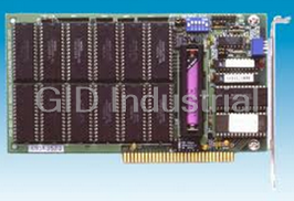
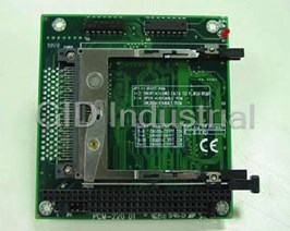
ADVANTECH PCA-6654

Description
Advantech PCA-6654 Video Display Card for Flat Panel and CRT
Part Number
PCA-6654
Price
Request Quote
Manufacturer
ADVANTECH
Lead Time
Request Quote
Category
EMBEDDED COMPUTING » EMBEDDED COMPUTING PERIPHERALS
Specifications
BIOS
27C512, multiple panel support (8 panels built in)
Chipset
CHIPS 65550, integrated flat panel/CRT VGA controller
CRT
Up to 1024 x 768 non-interlaced analog or multi-synch monitors with 64 K colors
Display support
Display centering and stretching features for optimal fit of VGA graphics and text on 800 x 600 and 1024 x 768 panels
Memory
2 MB EDO DRAM on board; 256 K x 16 DRAM sockets for frame buffer (optional)
Power
On-board DC-DC converter supplies LCD bias voltage; LCD backlight power supplied
Simultaneous CRT/LCD display
Available with TFT, DSTN, MONO and CRT
Simultaneous hardware cursor and pop-up window
64 x 64 pixels by 4 colors; 128 x 128 pixels by 2 colors
Slot
High performance 32-bit PCI bus add-on card
Windows GUI (Graphic User Interface) accelerator
64-bit Graphics Engine
Features
- 132 column text mode
- 640 x 480 resolution in graphics modes with 32K, 64K, and 16M colors
- High performance in Microsoft Windows
- Resolutions up to 1024 x 768 in graphics modes with 64 K colors
Datasheet

Extracted Text
PCA-6654/6654L
Video Display Card for Flat
Panel and CRT
Copyright Notice
This document is copyrighted by Advantech Co., Ltd. All rights are
reserved. Advantech Co., Ltd. reserves the right to make
improvements to the products described in this manual at any time
without notice.
No part of this manual may be reproduced, copied, translated, or
transmitted in any form or by any means without the prior written
permission of Advantech Co., Ltd. Information provided in this
manual is intended to be accurate and reliable. However, Advantech
Co., Ltd. assumes no responsibility for its use, nor for any
infringements upon the rights of third parties which may result from
its use.
All brand and product names mentioned herein are trademarks or
registered trademarks of their respective holders.
Warning: Do not set "V/H SYNC+Blank" in the Award BIOS of
your CPU card.
If the Video Off Method of POWER MANAGEMENT
SETUP in the Award BIOS is set on "V/H
SYNC+Blank", the VGA chip 65550 on board the
PCA-6654/6654L will not work properly after woken
from power saving mode.
Part No. 2002665400
1st Edition Printed in Taiwan July 1998
ii
Packing List
Before you set up the PCA-6654/6654L, make sure that the following
materials have been included with the package, and that this manual is
in good condition. If anything is missing or damaged, contact your
dealer immediately:
• PCA-6654/6654L card
• PCA-6654/6654L User's Manual
• PCA-6654/6654L installation driver
Introduction
PCA-6654
This is the standard version of the video display card. It contains
PanelLink features, which enables it to be used with Advantech's FPM
receiver series, including the FPM-37 and FPM-40.
PCA-6654L
This is the localized version of the video display card. It does not
contain PanelLink features. It has only one port for connection to an
LCD.
iii
PCA-6654 Board Layout
PCA-6654L Board Layout
iv
Additional Information and Assistance
1. Visit the Advantech web sites at www.advantech.com or
www.advantech.com.tw where you can find the latest information
about the product.
2. Contact your distributor, sales representative, or Advantech's
customer service center for technical support if you need
additional assistance. Please have the following information ready:
• Product name and serial number
• Description of your peripheral attachments
• Description of your software (operating system, version,
application software, etc.)
• Complete description of the problem
• Exact wording of any error messages
v
Safety Instructions
1. Read these safety instructions carefully.
2. Keep this user's manual for later reference.
3. Disconnect this equipment from any AC outlet before cleaning. Do not use
liquid or spray detergents for cleaning. Use a damp cloth.
4. For pluggable equipment, the power outlet must be installed near the
equipment and must be easily accessible.
5. Keep this equipment away from humidity.
6. Put this equipment on a reliable surface during installation. Dropping it or
letting it fall could cause damage.
7. The openings on the enclosure are for air convection. Protect the equipment
from overheating. DO NOT COVER THE OPENINGS.
8. Make sure the voltage of the power source is correct before connecting the
equipment to the power outlet.
9. Position the power cord so that people cannot step on it. Do not place anything
over the power cord.
10. All cautions and warnings on the equipment should be noted.
11. If the equipment is not used for a long time, disconnect it from the power
source to avoid damage by transient over-voltage.
12. Never pour any liquid into an opening. This could cause fire or electrical shock.
13. Never open the equipment. For safety reasons, the equipment should be opened
only by qualified service personnel.
14. If any of the following situations arises, get the equipment checked by service
personnel:
a. The power cord or plug is damaged.
b. Liquid has penetrated into the equipment.
c. The equipment has been exposed to moisture.
d. The equipment does not work well, or you cannot get it to work according
to the user's manual.
e. The equipment has been dropped and damaged.
f. The equipment has obvious signs of breakage.
15. DO NOT LEAVE THIS EQUIPMENT IN AN UNCONTROLLED
ENVIRONMENT WHERE THE STORAGE TEMPERATURE IS BELOW
-20° C (-4° F) OR ABOVE 60° C (140° F). IT MAY DAMAGE THE
EQUIPMENT.
The sound pressure level at the operator's position according to IEC 704-1:1982 is
equal to or less than 70 dB(A).
DISCLAIMER: This set of instructions is given according to IEC 704-1. Advantech
disclaims all responsibility for the accuracy of any statements contained herein.
vi
Wichtige Sicherheishinweise
1. Bitte lesen sie Sich diese Hinweise sorgfältig durch.
2. Heben Sie diese Anleitung für den späteren Gebrauch auf.
3. Vor jedem Reinigen ist das Gerät vom Stromnetz zu trennen. Verwenden
Sie Keine Flüssig-oder Aerosolreiniger. Am besten dient ein
angefeuchtetes Tuch zur Reinigung.
4. Die NetzanschluBsteckdose soll nahe dem Gerät angebracht und leicht
zugänglich sein.
5. Das Gerät ist vor Feuchtigkeit zu schützen.
6. Bei der Aufstellung des Gerätes ist auf sicheren Stand zu achten. Ein
Kippen oder Fallen könnte Verletzungen hervorrufen.
7. Die Belüftungsöffnungen dienen zur Luftzirkulation die das Gerät vor
überhitzung schützt. Sorgen Sie dafür, daB diese Öffnungen nicht
abgedeckt werden.
8. Beachten Sie beim AnschluB an das Stromnetz die AnschluBwerte.
9. Verlegen Sie die NetzanschluBleitung so, daB niemand darüber fallen
kann. Es sollte auch nichts auf der Leitung abgestellt werden.
10. Alle Hinweise und Warnungen die sich am Geräten befinden sind zu
beachten.
11. Wird das Gerät über einen längeren Zeitraum nicht benutzt, sollten Sie es
vom Stromnetz trennen. Somit wird im Falle einer Überspannung eine
Beschädigung vermieden.
12. Durch die Lüftungsöffnungen dürfen niemals Gegenstände oder
Flüssigkeiten in das Gerät gelangen. Dies könnte einen Brand bzw.
elektrischen Schlag auslösen.
13. Öffnen Sie niemals das Gerät. Das Gerät darf aus Gründen der
elektrischen Sicherheit nur von authorisiertem Servicepersonal geöffnet
werden.
14. Wenn folgende Situationen auftreten ist das Gerät vom Stromnetz zu
trennen und von einer qualifizierten Servicestelle zu überprüfen:
a - Netzkabel oder Netzstecker sind beschädigt.
b - Flüssigkeit ist in das Gerät eingedrungen.
c - Das Gerät war Feuchtigkeit ausgesetzt.
d - Wenn das Gerät nicht der Bedienungsanleitung entsprechend
funktioni ert oder Sie mit Hilfe dieser Anleitung keine Verbesserung
erzielen.
e - Das Gerät ist gefallen und/oder das Gehäuse ist beschädigt.
f - Wenn das Gerät deutliche Anzeichen eines Defektes aufweist.
Der arbeitsplatzbezogene Schalldruckpegel nach DIN 45 635 Teil 1000
beträgt 70dB(A) oder weiger.
DISCLAIMER: This set of instructions is given according to IEC704-1. Advantech
disclaims all responsibility for the accuracy of any statements contained herein.
vii
Contents
Chapter 1 Introduction .................................................. 1
1.1 Description ..........................................................................2
1.2 Specifications ......................................................................3
1.3 Driver Support ...................................................................4
1.4 Utility Support....................................................................5
1.5 Video BIOS .........................................................................5
1.6 Simultaneous Display Mode ..............................................6
Chapter 2 Hardware Setup ........................................... 7
2.1 Hardware Configuration ...................................................8
2.2 Jumpers and Connectors ...................................................9
Setting jumpers ....................................................................9
2.3 Jumpers, Connectors and Switches ................................10
2.4 Connectors for Adjuster ..................................................10
J4 ........................................................................................10
J5 ........................................................................................10
J9 ........................................................................................10
2.5 Board Layout - Jumpers, Connectors and Switches.....10
2.6 Jumper and Switch Settings ............................................12
2.6.1 LCD signal level select (J6) ......................................12
2.6.2 LCD bias voltage select (MONO) (J7) .....................12
2.6.3 LCD bias voltage select (J8) .....................................13
2.6.4 LCD type select (SW1) .............................................13
2.6.5 LCD clock configuration select (for PanelLink only)
(SW2) ........................................................................14
2.6.6 LCD control signal configuration select (for
PanelLink only) (SW3) .............................................14
2.7 LCD Setup ........................................................................15
2.7.1 Preliminary................................................................15
2.7.2 TFT LCD Setup ........................................................16
2.7.3 DSTN LCD Setup .....................................................18
2.7.4 MONO LCD Setup ...................................................21
viii
Chapter 3 Software Installation.................................. 25
3.1 Simultaneous Display Mode ............................................26
3.2 Installation for Windows 95 ............................................27
3.3 Installation for Windows NT ..........................................30
3.4 Installation for OS/2 ........................................................32
3.5 Further Information ........................................................35
Chapter 4 FPM Receiver Setup (PanelLink)
(for PCA-6654 only) ................................... 37
4.1 Introduction ......................................................................38
4.2 Jumpers and Connectors .................................................39
Setting jumpers ..................................................................39
4.3 Connectors ........................................................................40
4.4 Connectors for Adjuster ..................................................40
J1 ........................................................................................40
J2 ........................................................................................40
J7 ........................................................................................40
4.5 Board Layout - Connectors .............................................41
4.6 Jumpers and Switches .....................................................42
4.7 Board Layout - Jumpers and Switches ..........................43
4.8 Jumper and Switch Settings ............................................44
4.8.1 LCD bias voltage select (J5) .....................................44
4.8.2 LCD signal level select (J8) ......................................44
4.8.3 LCD bias voltage select (MONO) (J13) ...................45
4.8.4 LCD input clock select (J14) ....................................45
4.8.5 Backlight level select (J15) .......................................45
4.8.6 Power down select (J16) ...........................................46
4.8.7 LCD type select (S1) .................................................46
4.8.8 LCD clock configuration select (S2) ........................47
4.9 LCD Setup ........................................................................48
4.9.1 Preliminary................................................................48
4.9.2 TFT LCD Setup ........................................................49
4.9.3 DSTN LCD Setup .....................................................53
4.9.4 MONO LCD Setup ...................................................58
ix
Appendix A Pin Assignments - PCA-6654/6654L ..... 63
A.1 CRT Display (CN1) ..........................................................64
A.2 Flat Panel Display (CN2) .................................................65
A.3 Flat Panel Display Header (JP1) ....................................66
A.4 Keyboard Connector (J3) ................................................67
A.5 Backlight Power Connector (J10)...................................67
Appendix B Pin Assignments - FPM Receiver
(PanelLink) .............................................. 69
B.1 Flat Cable Panel Display Header (JP3) .........................70
B.2 Flat Cable Panel Display Extension Header (JP4)........71
B.3 Backlight Power (J3)........................................................71
B.4 Extension Power (J6) .......................................................71
B.5 Flat Panel Display (J10)...................................................72
B.6 FFC Connector (A) For Flat Panel Display (J11) .........73
B.7 FFC Connector (B) For Flat Panel Display (J12) .........74
B.8 Keyboard Connector (J17) ..............................................74
x
1
Introduction
• Description
• Specifications
• Driver Support
• Utility Support
• Video BIOS
• Simultaneous Display Mode
CHAPTER
1.1 Description
The PCA-6654/6654L is based on the CHIPS VGA flat panel/CRT
controller and is fully IBM VGA compatible. This controller offers a
large set of extended functions and higher resolutions, and it supports
simultaneous functioning. Since the PCA-6654/6654L VGA card is
fully compatible, you do not require any special drivers to operate in
standard modes. The enclosed software drivers allow you to take
advantage of the extended features of the PCA-6654/6654L:
• High performance in Microsoft Windows
• Resolutions up to 1024 x 768 in graphics modes with 64 K colors
• 640 x 480 resolution in graphics modes with 32K, 64K, and 16M
colors
• 132 column text mode
Warning! Be sure to turn off the power and unplug all
components before attempting to install or adjust the
PCA-6654/6654L. Make sure the jumpers are set
correctly before connecting the PCA-6654/6654L to
your flat panel display. Incorrect jumper settings
could damage your display.
2 PCA-6654/6654L User's Manual
1.2 Specifications
Chipset: CHIPS 65550, integrated flat panel/CRT VGA controller
Slot: High performance 32-bit PCI bus add-on card
BIOS: 27C512, multiple panel support (8 panels built in)
Memory: 2 MB EDO DRAM on board
256 K x 16 DRAM sockets for frame buffer (optional)
Windows GUI (Graphic User Interface) accelerator:
64-bit Graphics Engine
Simultaneous hardware cursor and pop-up window:
64 x 64 pixels by 4 colors
128 x 128 pixels by 2 colors
Simultaneous CRT/LCD display:
Available with TFT, DSTN, MONO and CRT
Display support:
Display centering and stretching features for optimal fit of VGA
graphics and text on 800 x 600 and 1024 x 768 panels.
CRT -
Up to 1024 x 768 non-interlaced analog or multi-synch monitors
with 64 K colors
Flat panel -
TFT LCD (Max resolution 1024 x 768, up to 64 K colors)
DSTN LCD (Max resolution 1024 x 768, up to 4096 colors)
MONO LCD (Up to 64 gray scales)
VESA standards supported (40 K BIOS only):
DPMS for CRT power-down (required for support of EPA
Energy- Star Program)
DDC for CRT plug and display control
Chapter 1 Introduction 3
Connectors:
MDR-26 for flat panel display (PanelLink)
DB-15 for CRT
Built-in 44-pin header for Advantech standard flat panel pin
assignment
Built-in housing to connect VR for adjusting contrast/brightness
Power:
On-board DC-DC converter supplies LCD bias voltage
LCD backlight power supplied
PanelLink:
High speed and low EMI operation
Flexible panel interface
1.3 Driver Support
The software driver provides for the following systems:
Software Name of VGA Driver Disk
Microsoft
Windows 95 PCA-6654 VGA Driver Windows 95 & NT 4.0
Microsoft
Windows NT 4.0 PCA-6654 VGA Driver Windows 95 & NT 4.0
IBM OS/2 PCA-6654 VGA Driver OS/2
4 PCA-6654/6654L User's Manual
1.4 Utility Support
The utility provides:
CT.COM Enable CRT display only
FP.COM Enable panel display only
SM.COM Enable both displays at the same time
REVERSE.EXE Reverse the displays' colors
READBIOS.EXE Read the VGA BIOS information
TESTDDC.EXE Test if the VGA BIOS supports DDC
These utilities are only supported in DOS mode, and can only be used
for testing.
1.5 Video BIOS
The standard BIOS chip supports eight kinds of flat panel displays:
1024 x 768 DSTN (Sharp LM14X82)
640 x 480 MONO (Sharp LM64P89)
640 x 480 DSTN (Kyocera KCB6448BSTT-X5)
800 x 600 DSTN
640 x 480 SHARP TFT
640 x 480 18-bit TFT (Toshiba LTM10C209A)
1024 x 768 TFT
800 x 600 TFT (Toshiba LTM10C273)
Note 1: To program the VGA BIOS to support the LCD only,
you must use the file "6654-STN.DAT" located on the
utility disk.
Note 2: The Chips 65550 chipset cannot support a 1024 x
768 DSTN LCD on SM mode, due to bandwidth
problems.
Chapter 1 Introduction 5
1.6 Simultaneous Display Mode
The PCA-6654/6654L supports simultaneous display to a CRT
monitor and a flat panel display. The flat panel may be TFT, DSTN or
MONO.
If you use a DSTN LCD in this mode, the display must be under
16/256 colors or the CRT and flat panel screens will tremble. You
must add a frame buffer with 512 K RAM and update the BIOS setup.
Call us for assistance.
6 PCA-6654/6654L User's Manual
2
Hardware Setup
• Hardware Configuration
• Jumpers and Connectors
• Jumpers, Connectors and Switches
• Connectors for Adjuster
• Board Layout - Jumpers, Connectors and
Switches
• Jumper and Switch Settings
• LCD Setup
- Preliminary
- TFT LCD Setup
- DSTN LCD Setup
- MONO LCD Setup
CHAPTER
2.1 Hardware Configuration
The PCA-6654/6654L is based on chipset 65550 and has high
performance, a simple configuration, and fully supported LCD/CRT.
BIOS
16 8
Address Data
RGB
CRT
H/V Sync
Display
32 DDC CLK/Data
Address
Power-on
32
ENAVEE sequencing &
Data 65550
DC-DC
ENAVDD
Converter
VDDSAFE VEESAFE
24
Control
Panel Data
Flat Panel
Panel Control Display
Address Data Address Data
88 32 16
Panel Link
2MB Video 512KB
Transmitter
Memory Frame Buffer
SiI 100/140
Data Pairs CLK Pair
3
32-Bit
PCI Bus Panel Link
Receiver
SiI 101/141
Control
Data
24/36
Flat Panel
Display
LCD Monitor
Figure 2-1: System block diagram
8 PCA-6654/6654L User's Manual
2.2 Jumpers and Connectors
Setting jumpers
You can configure your PCA-6654/6654L to match the needs of your
application by setting jumpers. A jumper is the simplest kind of
electrical switch. It consists of two metal pins and a small metal clip
(often protected by a plastic cover) that slides over the pins to connect
them. To “close” a jumper, you connect the pins with the clip. To
“open” a jumper you remove the clip. Sometimes a jumper will have
three pins, labeled 1, 2, and 3. In this case, you would connect either
pins 1 and 2 or pins 2 and 3.
3
2
1
Open Open Open Open Open Closed Closed Closed Closed Closed Closed 2 - 3 Closed 2 - 3 Closed 2 - 3 Closed 2 - 3 Closed 2 - 3
The jumper settings are schematically depicted in this manual as
follows:
1
Open Open Open Open Open Closed Closed Closed Closed Closed Closed 2 - 3 Closed 2 - 3 Closed 2 - 3 Closed 2 - 3 Closed 2 - 3
A pair of needle-nose pliers may be helpful when working with
jumpers.
If you have any doubts about the best hardware configuration for your
application, contact your local distributor or sales representative
before you make any changes.
Chapter 2 Hardware Setup 9
2.3 Jumpers, Connectors and Switches
Table 2-1: Jumpers, connectors, switches and their functions
Label Function
CN1 CRT display
CN2 Flat panel display
JP1 Flat panel display header
J3 Keyboard connector
J10 Backlight power connector
J4 DSTN LCD contrast adjustment
J5 MONO LCD contrast adjustment
J9 LCD brightness adjustment
J6 LCD signal level select
J7 LCD bias voltage select (MONO)
J8 LCD bias voltage select
SW1 LCD type select
SW2 LCD clock configuration select (for PanelLink only)
SW3 LCD control signal configuration select (for PanelLink only)
Please refer to Appendix A for pin assignments.
2.4 Connectors for Adjuster
J4
This is a 3-pin housing. Connect a 500 Ω external VR to adjust V ;
CON
voltage range 0 ~ +2.8 V.
J5
This is a 2-pin housing. Connect a 500 Ω external VR with on-board
R-23 to adjust V ; voltage range +5 ~ +40 V or 0 ~ -40 V,
EE
depending on the jumper setting.
J9
This is a 3-pin housing. Connect a 500 Ω external VR to adjust V ;
BR
voltage range 0 ~ +4.3 V.
10 PCA-6654/6654L User's Manual
2.5 Board Layout - Jumpers, Connectors and
Switches
J8: LCD bias
voltage select
J4: DSTN LCD
contrast
J7: LCD bias voltage
adjustment
select (MONO)
SW2: LCD clock
J5: MONO LCD
configuration select
contrast
adjustment
JP1: Flat panel
display header
SW1: LCD type
select
J9: LCD
SW3: LCD control
brightness
signal configuration
adjustment
select
J6: LCD signal
J10: Backlight
level select
power
connector
J3: Keyboard
CN1: CRT display
connector
CN2: Flat panel
display
Figure 2-2: Board layout - jumpers, connectors and switches
Chapter 2 Hardware Setup 11
2.6 Jumper and Switch Settings
Be sure the jumper and switch settings are correct before you install
the card to the chassis. Refer to Fig. 2-2 for jumper and switch
locations.
For information about installing an LCD into your system, refer to
Section 2. (LCD Setup) or Chapter 4 (FPM Receiver Setup) of this
manual.
2.6.1 LCD signal level select (J6)
Table 4-4: LCD signal level select (J6)
* 5 V 3.3 V
1 1
* default setting
2.6.2 LCD bias voltage select (MONO) (J7)
Table 4-5: LCD bias voltage select (MONO) (J7)
+V [+5 V ~ +40 V] * -V [0 V ~ -40 V]
EE EE
1 1
* default setting
12 PCA-6654/6654L User's Manual
2.6.3 LCD bias voltage select (J8)
Table 4-3: LCD bias voltage select (J8)
V [+5 ~ +40 V or 0 ~ -40 V for MONO LCD]
EE
1
* V [0 ~ +2.8 V for DSTN LCD]
CON
1
* default setting
2.6.4 LCD type select (SW1)
Table 2-5: LCD type select (SW1)
LCD type Pin 1 Pin 2 Pin 3 Pin 4
* 640 x 480 18-bit TFT OFF ON OFF ON
640 x 480 SHARP TFT ON ON OFF ON
800 x 600 TFT OFF OFF OFF ON
1024 x 768 TFT ON OFF OFF ON
640 x 480 DSTN ON OFF ON ON
800 x 600 DSTN OFF OFF ON ON
1024 x 768 DSTN ON ON ON ON
640 x 480 MONO OFF ON ON ON
* default setting
Chapter 2 Hardware Setup 13
2.6.5 LCD clock configuration select (for
PanelLink only) (SW2)
Table 2-6: LCD clock configuration select (for
PanelLink only) (SW2)
LCD type Pin 1 Pin 2 Pin 3 Pin 4
* TFT ON OFF ON OFF
640 x 480 DSTN OFF ON OFF ON
800 x 600 DSTN OFF ON OFF ON
1024 x 768 DSTN ON OFF OFF ON
640 x 480 MONO ON OFF ON OFF
* default setting
2.6.6 LCD control signal configuration select (for
PanelLink only) (SW3)
Table 2-7: LCD control signal configuration select (for PanelLink
only) (SW3)
Pin number and setting details
1 * The LCD input data are latched on falling edge of clock → ON
The LCD input data are latched on rising edge of clock → OFF
2 * The LCD control signals are latched on falling edge of clock → ON
The LCD control signals are latched on rising edge of clock → OFF
3 The SiI100 differential clock output is divided by two → ON
* The SiI100 differential clock output is divided by one → OFF
* default setting
14 PCA-6654/6654L User's Manual
2.7 LCD Setup
2.7.1 Preliminary
Make sure that your LCD is ready to match your PCA-6654/6654L
card prior to setting jumpers and switches. You will need to know
your LCD specifications, which will be among the following:
1. LCD type: TFT, DSTN or MONO
2. Number of pixels:
640 x 480, 800 x 600 or 1024 x 768 respectively
3. Supply voltage: 5 V or 3.3 V
4. LCD bias voltage for DSTN or MONO: Vmin., Vtyp., Vmax.
5. Backlight brightness voltage range in inverter
You must also have the following parts ready:
1. LCD cable, to connect the LCD to JP1
2. Inverter, which must match your LCD specifications
3. Inverter power wire, to connect the inverter to J10
4. 500 Ω VR assembly with wire, for adjusting brightness
5. 500 Ω VR assembly with wire, for adjusting contrast (DSTN or
MONO LCD only)
Note: If your DSTN LCD does not have a built-in DC/DC
converter, your must set up your LCD according to
the MONO LCD setup procedures, except for when
you set up SW1.
Chapter 2 Hardware Setup 15
2.7.2 TFT LCD Setup
Follow these steps:
1. Set SW1 according to the following table:
Table 2-8: TFT LCD setup (SW1)
LCD type Pin 1 Pin 2 Pin 3 Pin 4
* 640 x 480 18-bit TFT OFF ON OFF ON
640 x 480 SHARP TFT ON ON OFF ON
800 x 600 TFT OFF OFF OFF ON
1024 x 768 TFT ON OFF OFF ON
* default setting
2. Set SW2 as follows, for all TFT LCDs:
LCD type Pin 1 Pin 2 Pin 3 Pin 4
All TFT types ON OFF ON OFF
3. You do not need to set SW3.
4. Set J6 according to your LCD input power specifications:
Table 2-9: LCD signal level select (J6)
* 5 V 3.3 V
1 1 1
2 2
3 3
* default setting
5. You do not need to set J7 or J8.
6. Connect the LCD cable, inverter, inverter power wire, and VR
assembly with wire to J9. (See Fig. 2-3.)
7. Plug the VGA card into the PCI slot.
8. Power on the system.
9. Adjust the screen brightness using the VR control.
16 PCA-6654/6654L User's Manual
Inverter
Figure 2-3: TFT LCD setup
Chapter 2 Hardware Setup 17
Brightness VR
Inverter power wire
LCD cable
PCA-6654/6654L
2.7.3 DSTN LCD Setup
Follow these steps:
1. Set SW1 according to the following table:
Table 2-10: DSTN LCD setup (SW1)
LCD type Pin 1 Pin 2 Pin 3 Pin 4
640 x 480 DSTN ON OFF ON ON
800 x 600 DSTN OFF OFF ON ON
1024 x 768 DSTN ON ON ON ON
2. Set SW2 as follows, for all DSTN LCDs:
LCD type Pin 1 Pin 2 Pin 3 Pin 4
All DSTN types ON OFF ON OFF
3. You do not need to set SW3.
4. Set J6 according to your LCD input power specifications:
Table 2-11: LCD signal level select (J6)
* 5 V 3.3 V
1 1 1
2 2
3 3
* default setting
5. You do not need to set J7.
18 PCA-6654/6654L User's Manual
6. Set J8 as follows:
Table 2-12: LCD bias voltage select (J8)
V
CON
1 1
2
3
7. Connect the LCD cable, inverter, inverter power wire, and VR
assembly. The VR assembly with wire for brightness control
should be connected to J9, and the wire for contrast control
should be connected to J4. (See Fig. 2-4.)
8. Plug the VGA card into the PCI slot.
9. Power on the system.
10. Adjust the screen brightness and contrast using the VR controls.
Chapter 2 Hardware Setup 19
Inverter
Figure 2-4: DSTN LCD setup
20 PCA-6654/6654L User's Manual
Brightness VR Contrast VR
Inverter power wire
LCD cable
PCA-6654/6654L
2.7.4 MONO LCD Setup
Follow these steps:
1. Set SW1 as follows:
LCD type Pin 1 Pin 2 Pin 3 Pin 4
640 x 480 MONO OFF ON ON ON
2. Set SW2 as follows:
LCD type Pin 1 Pin 2 Pin 3 Pin 4
640 x 480 MONO ON OFF ON OFF
3. You do not need to set SW3.
4. Set J6 according to your LCD input power specifications:
Table 2-13: LCD signal level select (J6)
* 5 V 3.3 V
1 1 1
2 2
3 3
* default setting
5. Set J7 as follows:
Table 2-14: LCD bias voltage select (MONO) (J7)
+V -V
EE EE
1 1
1
2 2
3 3
Chapter 2 Hardware Setup 21
6. Set J8 as follows:
Table 2-15: LCD bias voltage select (J8)
V
EE
1
2
3
7. Plug the VGA card into the PCI slot.
8. Short J5.
9. Power on the system.
10. Adjust R-23 to be V max.
EE
11. Power off the system.
12. Remove the jumper on J5.
13. Connect the LCD cable, inverter, inverter power wire, and VR
assembly. The VR assembly with wire for brightness control
should be connected to J9, and the wire for contrast control
should be connected to J5. (See Fig. 2-5.)
14. Power on the system.
15. Adjust the screen brightness and contrast using the VR controls.
22 PCA-6654/6654L User's Manual
Inverter
Figure 2-5: MONO LCD setup
Chapter 2 Hardware Setup 23
Brightness VR Contrast VR
Inverter power wire
LCD cable
PCA-6654/6654L
24 PCA-6654/6654L User's Manual
3
Software Installation
This chapter describes the installation and
operation of the software drivers on the
display driver diskettes included in your
PCA-6654/6654L package. Sections in this
chapter include:
• Simultaneous Display Mode
• Installation for Windows 95
• Installation for Windows NT
• Installation for OS/2
• Further Information
CHAPTER
3.1 Simultaneous Display Mode
The 65550 VGA BIOS supports color TFT, color DSTN and
monochrome LCD flat panel displays. It also supports interlaced and
non-interlaced analog monitors (VGA color and VGA monochrome)
in high-resolution modes while maintaining complete IBM VGA
compatibility. Digital monitors (i.e. MDA, CGA, and EGA) are NOT
supported. Multiple frequency (multisync) monitors are supported as
analog monitors.
Both CRT and panel displays can be used simultaneously. The
PCA-6654/6654L can be set in one of three configurations: on a CRT,
on a flat panel display, or on both simultaneously. The system is
initially set to simultaneous display mode. In the utility diskettes,
there are three .COM files which can be used to select the display.
Simply type the file name at the DOS prompt:
CT.COM Enables CRT display only
FP.COM Enables panel display only
SM.COM Enables both displays at the same time
26 PCA-6654/6654L User's Manual
3.2 Installation for Windows 95
a. Select "Start" , "Settings" ,
1.
"Control Panel".
b. Double click the "display"
icon.
c. Choose the "Settings "
label.
d. Press the "Advanced
Properties" button.
a. Choose the "Adapter"
2.
label.
b. Press the "Change..."
button.
a. Press the "Have Disk..."
3.
button.
a. Insert the "VGA Driver
4.
Windows 95&NT 4.0"
disk into the floppy driver.
b. Type "A: \WIN95P.244".
c. Press the "OK" button.
Chapter 3 Software Drivers and Utilities 27
5.
a. Press the "OK" button.
6.
a. "Chips and Tech 65550PCI"
appear in the Adapter label.
b. Press the "Close" button.
7.
a. Press the "Yes" button
b. Close all windows to
reboot
a. Repeat Step 1 on the
8.
previous page of this
manual.
b. The "Chips" label appears
in "Display Properties".
c. Adjust the resolution and
color.
28 PCA-6654/6654L User's Manual
9.
a. Choose the "Chips" label.
b. Adjust the refresh rate and
display device.
c. Press the "OK" button
10.
a. Press the "OK" button to
change the display setting.
11.
a. Press the "OK" button to
confirm the setting.
END
Chapter 3 Software Drivers and Utilities 29
3.3 Installation for Windows NT
a. Select "Start" , "Settings" ,
1.
"Control Panel".
b. Double click the "display"
icon.
c. Choose the "Settings "
label.
d. Press the "Display Type"
button.
2.
a. Press the "Change..."
button.
3.
a. Press the "Have Disk..."
button.
4.
a. Insert the "VGA Driver
Windows 95&NT 4.0"
disk into the floppy driver.
b. Type "A:\WINNT4.115".
c. Press the "OK" button.
30 PCA-6654/6654L User's Manual
5.
a. Press the "OK" button.
6.
a. Press the "Yes" button
7.
a. Press the "OK" button
b. Close all windows to
reboot
a. Repeat Step 1 on the
8.
previous page of this
manual.
b. The "Chips" label appears
in "Display Properties".
c. Adjust the resolution, color
and refresh rate.
d. Press the "Test" button
to check the setting.
e. Press the "OK" button to
confirm the setting.
END
Chapter 3 Software Drivers and Utilities 31
3.4 Installation for OS/2
1.
a. Select "OS/2 System" ,
"Command Prompts" ,
"OS/2 Window".
b. Insert the "VGA Driver
OS/2" disk into the floppy
driver.
c. Type"A:",
Frequently asked questions
What makes Elite.Parts unique?

What kind of warranty will the PCA-6654 have?
Which carriers does Elite.Parts work with?
Will Elite.Parts sell to me even though I live outside the USA?
I have a preferred payment method. Will Elite.Parts accept it?
Why buy from GID?

Quality
We are industry veterans who take pride in our work

Protection
Avoid the dangers of risky trading in the gray market

Access
Our network of suppliers is ready and at your disposal

Savings
Maintain legacy systems to prevent costly downtime

Speed
Time is of the essence, and we are respectful of yours
Related Products

PC/104 to ISA Bus Adapter for PCM-4862
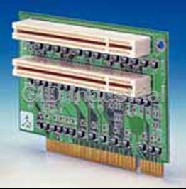
Riser card 2 x PCI for PCM-9570/9574/9576F/5864
Advantech PCM-231AV-00A1 Audio/TV-out Module | with Line-in, Line-out, Mic, Composite-video and S-Vi...
Request a Quote

The quote request has been received
Close

Facing challenges or have inquiries? Feel free to contact us!
Call Us +1-469-283-2440
What they say about us
FANTASTIC RESOURCE
One of our top priorities is maintaining our business with precision, and we are constantly looking for affiliates that can help us achieve our goal. With the aid of GID Industrial, our obsolete product management has never been more efficient. They have been a great resource to our company, and have quickly become a go-to supplier on our list!
Bucher Emhart Glass
EXCELLENT SERVICE
With our strict fundamentals and high expectations, we were surprised when we came across GID Industrial and their competitive pricing. When we approached them with our issue, they were incredibly confident in being able to provide us with a seamless solution at the best price for us. GID Industrial quickly understood our needs and provided us with excellent service, as well as fully tested product to ensure what we received would be the right fit for our company.
Fuji
HARD TO FIND A BETTER PROVIDER
Our company provides services to aid in the manufacture of technological products, such as semiconductors and flat panel displays, and often searching for distributors of obsolete product we require can waste time and money. Finding GID Industrial proved to be a great asset to our company, with cost effective solutions and superior knowledge on all of their materials, it’d be hard to find a better provider of obsolete or hard to find products.
Applied Materials
CONSISTENTLY DELIVERS QUALITY SOLUTIONS
Over the years, the equipment used in our company becomes discontinued, but they’re still of great use to us and our customers. Once these products are no longer available through the manufacturer, finding a reliable, quick supplier is a necessity, and luckily for us, GID Industrial has provided the most trustworthy, quality solutions to our obsolete component needs.
Nidec Vamco
TERRIFIC RESOURCE
This company has been a terrific help to us (I work for Trican Well Service) in sourcing the Micron Ram Memory we needed for our Siemens computers. Great service! And great pricing! I know when the product is shipping and when it will arrive, all the way through the ordering process.
Trican Well Service
GO TO SOURCE
When I can't find an obsolete part, I first call GID and they'll come up with my parts every time. Great customer service and follow up as well. Scott emails me from time to time to touch base and see if we're having trouble finding something.....which is often with our 25 yr old equipment.
ConAgra Foods