

 Manufacturers
Z-WORLD PK2200

Description
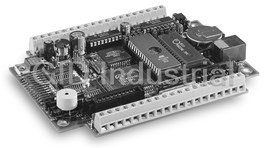
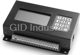
ZWorld PK2200 Embedded Computer - C-Programmable Controller. 18.432 MHz clock, 2 × 20 character LCD, 2 × 6 keypad, rugged metal enclosure
Part Number
PK2200
Price
Request Quote
Manufacturer
Z-WORLD
Lead Time
Request Quote
Category
PRODUCTS - P
Specifications
Board Size
4.0? × 5.32? × 0.63?.
Enclosure Size
4.0? × 5.5? × 1.35?.
Humidity
5% to 95% non-condensing.
Input Power
9–36VDC, switching p.s. Draws 40–70 mA.
Operating Temp.
–40°C to +70°C. With LCD, 0°C to 50°C.
Power Consumption
1.5W.
Processor
Z180. at 18.432 MHz [9.216 MHz optional].
Features
- Battery-backed real-time clock (RTC).
- Battery-backed static RAM, up to 512K bytes.
- EEPROM, 512 bytes standard.
- EPROM, up to 512K bytes, or flash memory to 256K bytes.
- Keypad, 2 rows of 6 keys, for a total of 12 keys. PK2240 has 4 rows of 3 keys.
- LCD. The standard screen has 2 lines of 20 characters. Other displays can be installed, on special order.
- Lithium backup battery, rated at 165 mA-hours. The RTC and full 512K RAM draw about 16 µA with power disconnected.
- Power failure warning interrupt.
- Self-resonating beeper
- Watchdog timer.
Datasheet

Extracted Text
C-Programmable Controller PK2200 Series The PK2200 Series of C-programmable controllers is based on the Zilog Z180 microprocessor. The PK2200 includes digital, se- rial, and high-current switching interfaces. The standard PK2200 includes a rugged enclosure with 2×20 LCD and 2×6 TM tactile keypad. The PK2200 also has a PLCBus expansion port, allowing you to connect several Z-World expansion boards (such as the XP8100 or XP8300) if you need extra I/O. The following PK2200 Series controllers are available: PK2200 With enclosure, 2×20 LCD, and 2×6 keypad. 18.432 MHz clock. PK2210 With enclosure, 2×20 LCD, and 2×6 keypad. 9.216 MHz clock. PK2200 or PK2210 with enclosure, LCD, and keypad PK2220 No enclosure, LCD, or keypad. 18.432 MHz clock. PK2230 No enclosure, LCD, or keypad. 9.216 MHz clock. PK2240 With enclosure, 128 x 64 backlit graphics LCD, 3×4 keypad. 18.432 MHz clock. The following PK2200 Series options are available: • 128K flash (32K EPROM is standard) • 128K or 512K RAM (32K is standard) • Backlit character LCD (with PK 2200 or PK2210) PK2220 or PK2230 (board-only) • Sourcing driver kit. Replaces sinking (2803) high-current driver chips with sourcing (2985) drivers. Features • Battery-backed static RAM, up to 512K bytes. • EPROM, up to 512K bytes, or flash memory to 256K bytes. • Battery-backed real-time clock (RTC). • Lithium backup battery, rated at 165 mA-hours. The RTC and full 512K RAM draw about 16 μA with power discon- nected. At that rate, the battery will sustain the RTC and RAM for about 1.1 years [10,000+ hours]. • Watchdog timer. • Power failure warning interrupt. PK2240 with backlit graphics LCD and 3 x 4 keypad • EEPROM, 512 bytes standard. • LCD. The standard screen has 2 lines of 20 characters. Other Specifications displays can be installed, on special order. Board Size 4.0″ × 5.32″ × 0.63″. • Keypad, 2 rows of 6 keys, for a total of 12 keys. PK2240 has Enclosure Size 4.0″ × 5.5″ × 1.35″. 4 rows of 3 keys. Operating Temp. –40°C to +70°C. With LCD, 0°C to 50°C. • Self-resonating beeper. Humidity 5% to 95% non-condensing. Input Power 9–36VDC, switching p.s. Draws 40–70 mA. Processor Z180. at 18.432 MHz [9.216 MHz optional]. Power Consumption 1.5W. 2900 Spafford Street Davis CA 95616 USA Tel: 530.757.3737 Fax: 530.753.5141 www.zworld.com Condensed Data Sheet: Rev. B PK2200 Series Z-World 530-757-3737 2 These inputs are convenient for detecting contact closures or The Interface sensing devices with open collector transistor outputs. The in- 1 16 protected digital inputs, with a 2.5 volt threshold. Three puts can detect CMOS logic levels if the low voltage level is of the inputs also function as counter inputs. less than 0.9V and the high voltage level is greater than 4.2V. 2 14 high-current outputs suitable for driving relays or sole- Inputs 1–8 can be read simultaneously and inputs 9–16 can be noids. These outputs can sink approximately up to 500 mA read simultaneously. Inputs 11 and 12 can be used as interrupt individually, at up to 48V, subject to total heat dissipation re- lines. Inputs 13 and 14 connect to the DMA request lines. strictions for the driver chips. Z-World software uses the two on-board DMA channels to 3 An RS485 serial port and an RS232 serial port operating at up implement high-speed counters. to 57,600 baud. You can have either JP2 R = 2K for inputs 11, 12, 13, and 14. (a) one RS232 channel (with CTS/RTS handshaking) and one +5V GND R = 22K otherwise half-duplex RS485 channel, or 4.7k Select [ ] (b) two 3-wire RS232 channels (no handshaking). IN 01:16 Inputs 1–8 or D0–D7 1–16 R TM 4A 26-pin expansion bus for Z-World PLCBus devices or 0.01 μF 9–16 customer-designed devices. Refer to the PLCBus data sheet. IN11 INT 0 The Terminals Z180 IN12 INT 2 There are 38 screw terminals (19 each side) used for input, out- IN13 CKA /DREQ 0 0 IN14 put, and power connections. There are also two connectors on DREQ 1 the sides of the controller: an RJ12 “phone jack” for the RS232 Jumper block JP2 allows you to apply pull-up or pull-down re- port, and a 26-pin connector for the expansion bus. The signals sistors to the digital inputs, in groups of eight. on the screw terminals are shown below. Signal Meaning When jumpered, the input impedence is 4.7 kΩ in the range +5V Output from 5V regulator 0–5V. Outside this range, the impedence is 3.9 kΩ. GND Ground High-Current Outputs PIN01–PIN16 Digital inputs There are 14 high-current outputs HV01–HV14 available at ex- +DC External power, nominally +24VDC. ternal terminals of the PK2200. These outputs can drive induc- Accepts 9–36VDC. tive loads, such as relays, small solenoids, or stepper motors. K Protection for high-current outputs HV01–HV14 High-current outputs Each output uses a common connector (“K”) for the protective 485+, 485– RS485 diodes. Sinking drivers (ULN2803) are standard. Sourcing driv- ers (ULN2985) are available as an option. Using the PK2200 Digital Inputs The 16 digital inputs accept an input voltage with a digital threshold at approximately 2.5 volts. The inputs are protected Figure 2. PK2200 Interface against overload over the range of ±48 volts. PLCBus Figure 1. PK2200 Block Diagram beeper GND DCIN PIN01 PIN01 K Beeper PIN02 PIN02 GND Z180 PIN03 HV01 Digital PIN03 HC01 PIN04 HV02 Input PIN04 HC02 PIN05 to LCD HV03 • PIN06 PIN05 HC03 Real-Time Clock High-Current HV04 to keypad • PIN07 HV05 PIN06 HC04 Output • PIN08 HV06 • PIN07 HC05 Battery • HV07 Protected High-Current PIN08 HC06 PIN09 HV08 Inputs Outputs +5V HC07 PIN10 RAM PIN11 PIN09 HC08 K Digital PIN12 PIN10 HC09 EPROM Input HV09 PIN13 PIN11 HC10 HV10 PIN14 PIN12 HC11 HV11 PIN15 High-Current EEPROM • PIN13 HC12 HV12 PIN16 • Output • HV13 PIN14 HC13 HV14 PIN15 HC14 battery RS232 PIN16 485+ Jack GND 485– PLCBus Keypad 485+ RS485 485– LCD LED RS-232 PK2200 Series Z-World 530-757-3737 3 These are the driver connections: The serial ports have a multiprocessor communications feature. external DC When enabled, an extra bit is included in the transmitted char- external DC your 1 2 inductive acter (where the parity bit would normally go). Receiving pro- K load [ ] JP1 HV 01:14 cessors can be programmed to ignore all received characters 2 K JP1 except those with the extra multiprocessing bits enabled. This 4 Channel Channel HV[01:14] (1–14) provides a 1-byte attention message that can wake up a proces- (1–14) your sor without the processor having to monitor (intelligently) all 4 3 inductive 1 3 JP1 load traffic on a shared communications link. JP1 UDN2985A ULN2803 JP1 JP1 1 2 1 2 The serial ports can be polled or interrupt-driven. Normal op- 3 4 3 4 tions are available: 7 or 8 data bits, 1 or 2 stop bits, odd, even or The ULN2803 is rated at 48V, with 500 mA maximum per chan- no parity, and parity, overrun, and framing error detection. nel. The maximum current per channel is approximately ~160 Refer to the Z180 MPU User’s Manual for detail. mA per output if all outputs are on at the same time continu- ously. The ULN2985 is rated at 30V max, It will carry ~140 mA LCD per output when all outputs are on simultaneously. The 2×20 LCD used with the PK2200 can come from one of sev- Battery-Backed Real-Time Clock eral vendors. All the LCDs are identical in operation, electrical The real-time clock (Toshiba TC8250) stores a representation of connections, and dimension. They may differ in timing. time and date, and runs independently, clocked at 32,768 Hz. Refer to any of the the LCD manufacturers’ data sheets for in- Refer to the manufacturer’s data sheet for details. formation regarding LCD operations. Beeper The LCD connector is a 2×7 header, H1. To operate the self-resonating beeper, write to address 0x140. Set bit 7 to turn it on; clear bit 7 to turn it off. Keypad To sample the 2×6 matrix keypad, read once from addresses The Serial Ports 1Bx and once from the corresponding addresses 1Ax . Each of H H Two ports support asynchronous serial communication at baud the low four address bits corresponds to a row of the keypad. rates from 300 to 57,600 (115,200 at 18.432 MHz) bits per sec- Addresses 1Bx return keypad columns 4 and 5 (in bits 4 and 5). ond. Using jumper block JP3, the drivers can be configured as Addresses 1Ax return keypad columns 0–3 in bits 4–7 respec- two 3-wire RS232 ports or one 5-wire RS232 port (with RTS and tively. You must negate the logic to get 1s for pressed keys. CTS handshaking) and one half-duplex RS485 port. This illustrates the configuration of two 3-wire RS232 channels: 2468 101214 Jumper block JP4 uses keypad signals (/KH2, and /KV1–/KV3) JP3 for operation mode settings. 13579 1113 TXD0 TXD0 /TX0 Row 1 is the bottom row. Column 0 is the rightmost column. RXD0 RXD0 /RX0 U12 Z180 13 11 (RS232) TXD1 /TX1 EEPROM 75 RXD1 /RX1 JP3 The EEPROM (512 bytes) contains a few factory-set parameters. /RTS0 RX485 /CTS0 485+ U9 Other than these, the EEPROM is for your use. TXD1 (RS485) 485– EN485 R11 4.7K Refer to the 24C04 manufacturer’s data sheet for information on Two 3-Wire RS232 reading and writing the EEPROM. The PK2200 lines SCL (serial This illustrates the configuration of one 5-wire RS232 channel clock), and SDA (serial data) apply. and one half-duplex RS485 channel: 2468 101214 Heat Sinking JP3 The PK2200 has one regulator. The aluminum enclosure pro- 13579 1113 vides the heat sink. In the board-only version, the mounting TXD0 TXD0 /TX0 RXD0 RXD0 /RX0 rails provide the heat sink. The regulator transfers heat through U12 Z180 TXD1 (RS232) /RTS0 two mounting “pem” nuts. Maximum dissipation by this regu- RXD1 /CTS0 lator is 1.5W when the ambient temperature is 50°C. Power dis- 911 /RTS0 5-Wire RS232 and sipation is given by the formula: 65 /CTS0 Half-Duplex RS485 JP3 78 RXD1 – 485+ P = (V 5) × (I + 0.15) IN TXD1 U9 485– (RS485) V = input voltage EN485 IN I = current, in amperes, drawn from +5V supply by external The Z180 has two independent asynchronous serial channels (0 accessories on bus or from the +5V terminal. and 1) with a separate baud rate generator for each channel. PK2200 Series Z-World 530-757-3737 4 Environmental Temperature Constraints is forced high (standby mode). The real-time clock and SRAM are switched to the lithium backup battery as the No special precautions are necessary over the range of 0–50°C regulated voltage falls below the battery voltage of approxi- (32–122°F). For operation at temperatures much below 0°C, the mately 3 volts. PK2200 should be equipped with a low temperature LCD. The heating effect of the power dissipated by the unit may be suffi- Jumpers and Headers cient to keep the temperature above 0°C, depending on the in- sulating capability of the enclosure used. The LCD unit is Figures 4–7 below show important headers and jumpers. Figure specified for a maximum operating temperature of 50°C. Ex- 8, next page, shows header and jumper positions. Pin 1 posi- cept for the LCD, which fades at higher temperatures, the tions are indicate by “+” markers. PK2200 can be expected to operate at 60°C, or more, without problem. 1 2 GND VCC (+5V) 1 3 4 /RTS0 or /TX1 attention /AT DCIN (unregulated) 2 GND strobe /STBX 5 6 GND Expansion Bus /TX0 3 APLC3 7 8 GND /RX0 4 APLC2 9 10 GND TM The PLCBus is a general purpose expansion bus for Z-World /CTS0 or /RX1 5 11 12 APLC1 GND 6 13 14 +5V DPLC6 DPLC7 controllers. Multiple expansion boards may be daisy-chained DPLC4 15 16 DPLC5 together and connected to a Z-World controller to form an ex- DPLC2 17 18 DPLC3 Figure 5. J2, DPLC0 19 20 DPLC1 tended system. For details, refer to the PLCBus Data Sheet. 21 22 “Phone” Jack /WRX LCDX 23 24 /RDX APLC0 (+5V) VCC 25 26 GND Power Failure Interrupts Figure 4. H2, The following events occur when power fails: 1 /KV0 PLCBus connector 2 /KV1 1 The power-failure NMI (non-maskable interrupt) is triggered 3 /KV2 Keypad columns 4 /KV3 when the unregulated DC input voltage falls below approxi- DPLC6 1 2 DPLC7 5 /KV4 DPLC4 3 4 DPLC5 6 /KV mately 7.9 volts (subject to the voltage divider R1/R2). DPLC2 5 6 DPLC3 7 /KH0 DPLC0 7 8 DPLC1 8 /KH1 Keypad rows 2 The system reset is triggered when the regulated +5V supply 9 10 /WRX LCDX 9 /KH2 VLC 11 12 APLC0 falls below 4.5 volts. The reset remains enabled as the volt- 10 /KH3 GND 13 14 VCC age falls further. At this point, the chip select for the SRAM Figure 7. H3, Figure 6. H1, Keypad Connector LCD Connector U10, U16 are under the EPROM DCIN U8, U11 are under the SRAM Figure 3. Parts Locations J1 LED JP1 U2 U3 L1 C1 H.C. Driver JP2 JP3 LCD U1 U5 U6 U7 U9 U4 PLD Buffer RS232 U12 RS232 Y1 H1 U13 Battery Buffer RT U15 U17 RTC U14 Inv. J2 Z180 H2 Phone Jack Mux Y2 U20 Beeper U18 Mux Mux U19 JP4 H3 Keypad JP5 Reset J3 Button PLC Bus Connector EPROM SRAM 485 PK2200 Series Z-World 530-757-3737 5 4.76 Board Dimensions JP1 Figure 8 shows board dimensions, mounting 1 2 3 4 hole locations and sizes, all the jumpers and (1.50, 2.95) H1 to LCD JP2 JP3 headers, and pin 1 positions for important headers. Mounting holes are (0.22, 0.77) 0.160 dia, 4x from the extreme edges of the board. PLC Bus Connector H2 Maximum height of components above the (0.53, 1.60) board is 0.5″ approximately. Overall height JP4 to keypad (flex cable) JP5 is 0.63″ approximately. H3 CN1 CN2 (2.0, 0.7) Enclosure Dimensions Figures 9 and 10 show the size of the alumi- 0.22 typ num enclosure, the locations of the PLCBus 5.32 port, phone jack, and LED, and the apertures for the keypad and LCD. Keys are 14 mm square and on 17 mm centers. The PK2240 enclosure is fundamentally the same as the enclosure for the PK2200, Figure 8. Board Dimensions PK2210, PK2220, and PK2230. Only the LCD and keypad locations differ. 1.2 1.71 3.09 2.855 2.42 2.717 1.85 1.262 1.35 0.67 1.105 0.37 0.37 0.2 typ 0.2 typ 4.0 4.0 Figure 10. PK2240 Panel Dimensions 2.95 1.44 Figure 9. Enclosure Dimensions, PK2200–PK2230 4.85 4.39 4.35 1.15 1.11 menu item field help setup run up down init F1 F2 F3 F4 del add 10-32 clr, 4x 0.75 0.55 0.31 typ 0.22 0.2 ~0.5 0.77 typ 5.5 ~0.63 1.455 4.0 5.100 4.85 3.750 3.340 0.621 789 456 123 –0 . 10-32 clr, 4x 0.31 typ 5.5 GND PIN01 PIN02 PIN03 PIN04 PIN05 PIN06 PIN07 PIN08 +5V PIN09 PIN10 PIN11 PIN12 PIN13 PIN14 PIN15 PIN16 GND
Frequently asked questions
What makes Elite.Parts unique?

What kind of warranty will the PK2200 have?
Which carriers does Elite.Parts work with?
Will Elite.Parts sell to me even though I live outside the USA?
I have a preferred payment method. Will Elite.Parts accept it?
Why buy from GID?

Quality
We are industry veterans who take pride in our work

Protection
Avoid the dangers of risky trading in the gray market

Access
Our network of suppliers is ready and at your disposal

Savings
Maintain legacy systems to prevent costly downtime

Speed
Time is of the essence, and we are respectful of yours
Related Products
Request a Quote

The quote request has been received
Close

Facing challenges or have inquiries? Feel free to contact us!
Call Us +1-469-283-2440
What they say about us
FANTASTIC RESOURCE
One of our top priorities is maintaining our business with precision, and we are constantly looking for affiliates that can help us achieve our goal. With the aid of GID Industrial, our obsolete product management has never been more efficient. They have been a great resource to our company, and have quickly become a go-to supplier on our list!
Bucher Emhart Glass
EXCELLENT SERVICE
With our strict fundamentals and high expectations, we were surprised when we came across GID Industrial and their competitive pricing. When we approached them with our issue, they were incredibly confident in being able to provide us with a seamless solution at the best price for us. GID Industrial quickly understood our needs and provided us with excellent service, as well as fully tested product to ensure what we received would be the right fit for our company.
Fuji
HARD TO FIND A BETTER PROVIDER
Our company provides services to aid in the manufacture of technological products, such as semiconductors and flat panel displays, and often searching for distributors of obsolete product we require can waste time and money. Finding GID Industrial proved to be a great asset to our company, with cost effective solutions and superior knowledge on all of their materials, it’d be hard to find a better provider of obsolete or hard to find products.
Applied Materials
CONSISTENTLY DELIVERS QUALITY SOLUTIONS
Over the years, the equipment used in our company becomes discontinued, but they’re still of great use to us and our customers. Once these products are no longer available through the manufacturer, finding a reliable, quick supplier is a necessity, and luckily for us, GID Industrial has provided the most trustworthy, quality solutions to our obsolete component needs.
Nidec Vamco
TERRIFIC RESOURCE
This company has been a terrific help to us (I work for Trican Well Service) in sourcing the Micron Ram Memory we needed for our Siemens computers. Great service! And great pricing! I know when the product is shipping and when it will arrive, all the way through the ordering process.
Trican Well Service
GO TO SOURCE
When I can't find an obsolete part, I first call GID and they'll come up with my parts every time. Great customer service and follow up as well. Scott emails me from time to time to touch base and see if we're having trouble finding something.....which is often with our 25 yr old equipment.
ConAgra Foods