

 Manufacturers
WARNER ELECTRIC 5370-169-041

Description
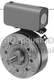
Warner Electric 5370-169-041 BRAKE FOR EM100-20 90V
Part Number
5370-169-041
Price
Request Quote
Manufacturer
WARNER ELECTRIC
Lead Time
Request Quote
Category
PRODUCTS - 5
Datasheet

Extracted Text
PHASE 2 Electro Module EM Series Individual Clutch or Brake Module Combine to Comprise a Clutch, Brake or Clutch/Brake Combination! Electro Modules are individual clutch or brake units which are assembled together to comprise a clutch, brake, or clutch/brake combination. Electro Modules can be bolted directly to a NEMA C-face motor or reducer or they can be base mounted for stand alone operation. Electro Modules offer the ultimate in clutch/brake convenience. They are easy and quick to install and require no lubrication or maintenance for life. Bolt-it-down and wire-it-up ... it’s ready to go! Modular design flexibility 1/4 to 7-1/2 HP at 1800 RPM Outstanding controllability Fast cycling Original Design Smooth starts and stops Sizes 210 & 215 Accurate GEN 2 Design Bidirectional Sizes 50, 100 & 180 Consistent performance Complete control capability Power-Off (Electrically Released) Selection Flexibility Clutch/Brake Applications Controls Combination Electrically released operation is the Warner Electric controls assure that you A wide range of module combinations for primary feature of power-off Electro get the maximum performance from your use with motors, reducers and other Module brakes. They can be used as Electro Module. See page 141 in standard power transmission brakes, motor brakes and in Clutch/Brake catalog P-1234. components is available. The flexibility of combination with clutches. See pages Electro Module enables you to pick the 39 and 50 for complete information. exact combination of function and design. Selection The correct size can be determined from Power-On Applications easy-to-use selection charts based on Electro Modules for power-on NEMA frame sizes or horsepower and applications are purchased as individual shaft speed. Examples show the right clutches and brakes to be assembled for way to order the Electro Module C-face, flange, or base mounting required. applications. Warner Electric 800-825-6544 23 EM Series Electro Module Modular Components Clutch Modules Clutch Combinations Clutch/Brake Combinations 10 Motor Clutch 10/40 Fan cooled for long life and consistent 10/20 Motor Clutch/Output Clutch performance. See page 29. Motor Clutch/Brake Use for clutch only applications. Has hollow Use for clutch/brake applications. Hollow bore input for mounting directly to C-face bore input. Shaft on output side. Basic motors. Shaft and C-face on output side of components are field, rotor, 2 armatures unit accommodates reducer, parallel drive and power-on magnet. See page 34. or coupling. Basic components are field, rotor and armature. See page 35. 30 Input Clutch Fan cooled. Sealed coil. Twin bearing mounted shaft maintains tight concentricities. See page 32. 30/40 20/30 Input Clutch/Output Clutch Brake/Input Clutch Use for clutch only applications. Features Use for clutch/brake applications. dual C-faces and shafts. Unit input from Features dual C-faces and shafts. Input parallel drive or coupling. Output to from parallel drive or coupling. Output to 40 Output Clutch reducer. Basic components are field, rotor reducer. Basic components are field, rotor, Autogap™ automatically adjust armature for and armature. See page 37. 2 armatures and power-on magnet. wear. Does not have a coil – use in See page 36. combination with a 10 Motor Clutch or 30 Input Clutch module. See page 33. Brake Modules 20/30-B 30/40-B Brake/Input Clutch–Base Mounted Input Clutch/Output 20 Brake Stand alone units attach with pulleys, Clutch–Base Mounted Bolts directly to C-face components. sprockets, etc. See page 36. Base mounting allows the clutch units to be See page 30. utilized as a separate drive unit. Attach with pulleys, sprockets, etc. See page 37. 20MB Motor Brake Does not have a shaft. Has end cap. See page 31 . 24 Warner Electric 800-825-6544 Electro Module EM Series Selection Electro Module clutch or brake units may b. Base Mounting 2. Determine Technical be mounted directly to NEMA C-face Requirements Technical considerations for sizing and motors and reducers, or can be base selection are torque and heat dissipation. mounted. Each merits careful consideration, 1. Select Configuration especially heat dissipation as over time, use in excessive temperature a. NEMA C-face Mounting environments will have an adverse effect on bearing life and coil wire insulation integrity. Electro Module assemblies may be Compare the calculated torque mounted as separate drive units driven requirement with the average dynamic from the prime mover by V-belts, chain torque ratings. Select a unit with and sprockets, couplings, timing belts adequate torque. If the unit selected on and other standard power transmission torque is different than the unit selected components. based on heat, select the larger size unit. Select the correct size module from the Horsepower vs. Shaft Speed chart by determining the motor horsepower and RPM at the module location. The Based on the NEMA C-face frame size correct size Electro Module is shown of the prime mover, select the correct at the intersection of the HP and clutch or brake module size from the operating speed. Frame Size Selection chart. Size 100 For additional sizing information, refer houses the components of the size 180 to the technical sizing procedure in a size 50 frame, while size 215 (step 2). incorporates size 210 components. Frame Size Selection Horsepower vs. Shaft Speed NEMA Frame Size Electro Module Size HP SHAFT SPEED AT CLUTCH (IN RPM) EM-50* 100 200 300 400 500 600 700 800 900 1000 1100 1200 1500 1800 2000 2400 3000 3600 56C/48Y EM-100** 1/4 182C/143TC EM-50 EM-180 1/2 184C/145TC 3/4 213C/182TC EM-210 1 215C/184TC EM-100 or EM-180 1-1/2 213TC/215TC EM-215 * For 56C/48Y Frame motors 3/4 HP and smaller the 2 UM-100 size may be used where extended life is 3 desirable. EM-210 or EM-215 ** UM-100 size is recommended for motors 1 HP and larger. 5 7-1/2 Warner Electric 800-825-6544 25 EM Series Electro Module a. Heat Dissipation Sizing Heat dissipation requirement is Compare the calculated heat Friction surfaces slip during the initial calculated as follows: generated in the application to the unit period of engagement and, as a result, ratings using the heat dissipation 2 2 E = 1.7 x WR x (N/100) x F heat is generated. The clutch/brake curves. Select the appropriate unit that selected must have a heat dissipation where: has adequate heat dissipation ability. rating greater than the heat generated E = Heat (lb. ft./min.) by the application. Therefore, in high 2 inertia or high cycle rate applications, WR = Total reflected inertia at the it is necessary to check the heat clutch/brake shaft. Include the 2 dissipation carefully. Inertia, speed clutch/brake output inertia. (lb.ft. ) and cycle rate are the required N = Speed in revolutions per minute parameters. (RPM) F = Cycle rate in cycles per minute (CPM) Heat Dissipation Curves Size 50 Size 100/180 Size 210/215 Maximum Speed 3600 RPM Maximum Speed 3600 RPM Maximum Speed 3600 RPM 12000 36000 12000 10000 10000 30000 250° F 24000 8000 8000 250° F 250° F 18000 6000 6000 200° F 220° F 4000 4000 12000 200° F 2000 2000 6000 0 0 0 900 1800 2700 3600 0 900 1800 2700 3600 900 1800 2700 3600 Speed (RPM) Speed (RPM) Speed (RPM) The torque requirements are b. Torque Sizing For some applications, the torque calculated as follows: For most applications, the correct size requirement is determined by the time clutch/brake can be selected from the allowed to accelerate and decelerate 2 T = (WR x N) / (308 x t) Horsepower vs. Shaft Speed chart. the load. (This time is generally where: specified in milliseconds.) For these Determine the motor horsepower and applications, it is necessary to T = Average Dynamic Torque (lb. ft.) the RPM at the clutch/brake. The determine the torque requirement correct size unit is shown at the 2 WR = Total reflected inertia at the based on load inertia and the time intersection of horsepower and shaft clutch/brake shaft. Include the allowed for engagement. speed. 2 clutch/brake output inertia. (lb. ft. ) If the static torque requirements are N = Speed in revolutions per minute known, refer to the Specifications Table (RPM) to select a unit. t = Time allowed for the engagement (sec) C-face Clutch/Power-on Brake Dynamic Torque Curves Size 100/180 Size 50 Size 210/215 Maximum Speed Maximum Speed Maximum Speed 3600 RPM Static Torque 16 lb.ft. 3600 RPM Static Torque 30 lb.ft. 3600 RPM Static Torque 95 lb.ft. 32 16 96 14 28 84 12 24 72 20 10 60 100% Current 100% Current 8 16 48 12 6 36 100% Current 50% Current 50% Current 4 8 24 50% Current 4 2 12 0 0 0 0 900 1800 2700 3600 0 900 1800 2700 3600 0 900 1800 2700 3600 Speed Difference in RPM Speed Difference in RPM Speed Difference in RPM 26 Warner Electric 800-825-6544 Dynamic Torque (lb.ft.) Heat Dissipation (ft. lbs./min.) Dynamic Torque (lb.ft.) Heat Dissipation (ft. lbs./min.) Dynamic Torque (lb.ft.) Heat Dissipation (ft. lbs./min.) Electro Module EM Series Specifications (Blue shaded areas indicate GEN 2 design) EM Size Static Torque lb. ft. Maximum RPM Voltage D.C. 50 16 3600 6, 24, or 90 100 30 3600 6, 24, or 90 180 30 3600 6, 24, or 90 210 95 3600 6, 24, or 90 215 95 3600 90 3. Accessories 4. Select Control Warner Electric Electro Modules can be Warner Electric manufactures fitted with several accessories to extend clutch/brake controls to meet several their capacity and ease of mounting. system functions including: a. Conduit Box On/Off NEMA 4 and UL listed, available in standard and washdown versions. Torque adjust Over excitation Position loop Many requirements beyond function can impact control selection. See the Controls Section on page 141 in Clutch/Brake Catalog P-1234 for complete information. b. Mounting Brackets Two styles of mounting brackets are available for simplified installation. The base mount is used with the 20/30 and 30/40 configurations. A motor mount is also available and provides sturdy support for 20, 10/20 and 10/40 units and motor. Base Mount Motor Mount Motor Mount For 50, 100 & 180 sizes For 210 & 215 sizes c. Cover Kit – For sizes 50, 100 & 180 Each cover kit includes two (2) vent covers and four (4) screws needed to convert a vented design into an enclosed design (non-washdown). Warner Electric 800-825-6544 27 EM Series Electro Module Ordering Information Part Numbers Only 50, 100, and 180 sizes of the models listed will be converted to the new GEN 2 design. 210 and 215 sizes will continue to be offered in the original design and will not be converted. (Blue shaded areas indicate GEN 2 design) Model No. Voltage D.C. GEN 2 Part No. Original Part No. Model No. Voltage D.C. GEN 2 Part No. Original Part No. 10 Motor Clutch Module 40 Output Clutch Module EM-50-40 5370-536-200 5370-536-008 EM-50-10 6 5370-270-201 5370-270-020 EM-100-40 5370-536-201 5370-536-007 EM-50-10 24 5370-270-203 5370-270-030 EM-180-40 5370-536-202 5370-536-009 EM-50-10 90 5370-270-204 5370-270-015 EM-210-40 5371-536-005 EM-100-10 6 5370-270-206 5370-270-045 EM-100-10 24 5370-270-208 5370-270-056 EM-100-10 90 5370-270-209 5370-270-046 Accessories EM-180-10 6 5370-270-211 5370-270-021 Description EM Size Part No. EM-180-10 24 5370-270-213 5370-270-055 Conduit Box All sizes 5370-101-042 EM-180-10 90 5370-270-214 5370-270-017 Base Mount Kit 50/100 5370-101-004 EM-210-10 6 5371-270-011 for 2030, 3040 180 5370-101-002 EM-210-10 24 5371-270-027 210/215 5371-101-001 EM-210-10 90 5371-270-009 Motor Mount Kit 50/100 5370-101-078 20 Brake Module for 20, 1020, 1040 180 5370-101-079 EM-50-20 6 5370-169-201 5370-169-043 210/215 5371-101-012 EM-50-20 24 5370-169-203 5370-169-045 Cover Kit 50/100/180 5370-101-076 EM-50-20 90 5370-169-204 5370-169-042 50/100/180 5370-101-082 (20 or 20MB) EM-100-20 6 5370-169-206 5370-169-040 EM-100-20 24 5370-169-208 5370-169-072 EM-100-20 90 5370-169-209 5370-169-041 EM-180-20 6 5370-169-211 5370-169-050 EM-180-20 24 5370-169-213 5370-169-071 How to Order EM-180-20 90 5370-169-214 5370-169-051 Motor or Reducer Mounted EM-210-20 6 5371-169-022 EM-210-20 24 5371-169-034 Simply combine the size number with the configuration of the EM-210-20 90 5371-169-023 modular combination from page 24. Specify voltage. See EM-215-20 90 5371-169-076 chart for specific part numbers. Power-off brake Electro Modules are found on page 39. Order optional conduit box if 20MB Motor Brake desired. EM-50-20MB 6 5370-169-216 5370-169-047 EM-50-20MB 24 5370-169-218 5370-169-062 Example EM-50-20MB 90 5370-169-219 5370-169-048 EM-180 10 – 20 90 Volt EM-180-20MB 6 5370-169-221 5370-169-053 Brake EM-180-20MB 24 5370-169-223 5370-169-073 Motor Clutch EM-180-20MB 90 5370-169-224 5370-169-054 Size EM-210-20MB 6 5371-169-025 EM-210-20MB 24 5371-169-035 Base Mounted EM-210-20MB 90 5371-169-026 Simply combine the size number with the configuration of the 30 Input Clutch Module modular combination from page 24. Specify voltage. See EM-50-30 6 5370-270-216 5370-270-019 chart for specific part numbers. Power-off brake Electro EM-50-30 24 5370-270-218 5370-270-052 Modules are found on page 39. Order optional conduit box if EM-50-30 90 5370-270-219 5370-270-016 desired. EM-100-30 6 5370-270-221 5370-270-047 Example EM-100-30 24 5370-270-223 5370-270-054 EM-180 20 – 30 - B 90 Volt EM-100-30 90 5370-270-224 5370-270-048 Base EM-180-30 6 5370-270-226 5370-270-049 Input Clutch EM-180-30 24 5370-270-228 5370-270-053 Brake EM-180-30 90 5370-270-229 5370-270-050 Size EM-210-30 6 5371-270-023 EM-210-30 24 5371-270-026 Select Appropriate Power Supply/Control. See the Controls EM-210-30 90 5371-270-024 Section beginning on page 141 in Clutch/Brake Cat. #P-1234. 28 Warner Electric 800-825-6544 Electro Module EM Series 10 Motor Clutch Module A C E F 1/2"-NPT G øB øD Dimensions (Blue shaded areas indicate GEN 2 design) Size A B C D E F G 50 1.555 .625 .780 6.750 0° 36 3/16 x 3/16 100 1.555 .625 .780 6.750 0° 36 3/16 x 3/16 180 1.555 .875 .780 6.750 0° 36 3/16 x 3/16 210 1.313 1.125 .700 9.250 65° 36 1/4 x 1/4 Specifications (Blue shaded areas indicate GEN 2 design) 2 2 Model Size Voltage DC Static Torque lb. ft. Max. RPM Inertia–WR (lb.ft. ) Weight (lbs) NEMA Frame Size 50 6, 24, 90 16 3600 .020 6.4 56C/48Y* 100 6, 24, 90 30 3600 .046 7.6 56C/48Y** 182C/143TC 180 6, 24, 90 30 3600 .046 7.6 184C/145TC 213C/182TC 210 6, 24, 90 95 3600 .188 9.1 215C/184TC * For 56C/48Y Frame motors 3/4 HP and smaller the UM-100 size may be used where extended life is desirable. ** UM-100 size is recommended for motors 1 HP and larger. For standard NEMA frame dimensions, see page 64. Only 50, 100, and 180 sizes of the models listed will be converted to the new GEN 2 design. 210 size will continue to be offered in the original design and will not be converted. Warner Electric 800-825-6544 29 EM Series Electro Module 20 Brake Module A G B C E 1/2"-NPT H J J øD øD øF Dimensions (Blue shaded areas indicate GEN 2 design) Size A B C D E F G H J 50 5.165 3.125 2.040 .625 1.150 6.750 0° 36 3/16 x 3/16 100 5.186 3.125 2.061 .625 1.150 6.750 0° 36 3/16 x 3/16 180 5.246 3.125 2.121 .875 1.150 6.750 0° 36 3/16 x 3/16 210 7.578 4.609 2.500 1.125 1.812 9.250 20° 36 1/4 x 1/4 215 8.078 4.609 3.000 1.375 1.812 9.250 20° 36 5/16 x 5/16 Specifications (Blue shaded areas indicate GEN 2 design) 2 Model Size Voltage DC Static Torque lb. ft. Max. RPM Armatures Inertia–WR Arm. Hub Shaft Weight (lbs) NEMA Frame Size 50 6, 24, 90 16 3600 .014 .002 .001 9.2 56C/48Y* 100 6, 24, 90 30 3600 .036 .003 .002 11.2 56C/48Y** 182C/143TC 180 6, 24, 90 30 3600 .036 .003 .002 11.2 184C/145TC 213C/182TC 210 6, 24, 90 95 3600 .162 .021 .017 21.5 215C/184TC 215 90 95 3600 .162 .021 .019 22 213TC/215TC*** * For 56C/48Y Frame motors 3/4 HP and smaller the EM-100 size may be used where extended life is desirable. ** EM-100 size is recommended for motors 1 HP and larger. *** For 7-1/2 HP max. For standard NEMA frame dimensions, see page 64. Only 50, 100, and 180 sizes of the models listed will be converted to the new GEN 2 design. 210 and 215 sizes will continue to be offered in the original design and will not be converted. 30 Warner Electric 800-825-6544 Electro Module EM Series 20MB Motor Brake Module A B G C 1/2"-NPT H F øD øE Dimensions (Blue shaded areas indicate GEN 2 design) Size A B C D E F G H 50 3.368 3.125 1.150 .625 6.750 3/16 x 3/16 0° 36 180 3.368 3.125 1.150 .875 6.750 3/16 x 3/16 0° 36 210 5.150 4.610 1.812 1.125 9.250 1/4 x 1/4 20° 36 Specifications (Blue shaded areas indicate GEN 2 design) 2 Model Size Voltage DC Static Torque lb. ft. Max. RPM Armatures Inertia–WR Arm. Hub Input Hub Weight (lbs) NEMA Frame Size 50 6, 24, 90 16 3600 .014 .002 .001 9.2 56C/48Y* 182C/143TC 180 6, 24, 90 30 3600 .036 .003 .002 11.2 184C/145TC 213C/182TC 210 6, 24, 90 95 3600 .162 .021 .017 21.5 215C/184TC *For 56C/48Y Frame motors 3/4 HP and smaller the EM-100 size may be used where extended life is desirable. For standard NEMA frame dimensions, see page 64. Only 50 and 180 sizes of the models listed will be converted to the new GEN 2 design. 210 size will continue to be offered in the original design and will not be converted. Warner Electric 800-825-6544 31 EM Series Electro Module 30 Input Clutch Module A C B E G 1/2"-NPT H J øD øF Dimensions (Blue shaded areas indicate GEN 2 design) Size A B C D E F G H J 50 4.327 2.265 2.040 .625 1.490 6.750 0° 36 3/16 x 3/16 100 4.326 2.265 2.061 .625 1.490 6.750 0° 36 3/16 x 3/16 180 4.386 2.265 2.121 .875 1.490 6.750 0° 36 3/16 x 3/16 210 5.391 2.438 2.500 1.125 1.812 9.250 65° 36 1/4 x 1/4 Specifications (Blue shaded areas indicate GEN 2 design) 2 Inertia–WR Model Size Voltage DC Static Torque lb. ft. Max. RPM Rotor Shaft Weight (lbs) NEMA Frame Size 50 6, 24, 90 16 3600 .020 .001 9.2 56C/48Y* 100 6, 24, 90 30 3600 .046 .002 10.5 56C/48Y** 182C/143TC 180 6, 24, 90 30 3600 .046 .002 10.5 184C/145TC 213C/182TC 210 6, 24, 90 95 3600 .188 .017 19.8 215C/184TC * For 56C/48Y Frame motors 3/4 HP and smaller the EM-100 size may be used where extended life is desirable. ** EM-100 size is recommended for motors 1 HP and larger. For standard NEMA frame dimensions, see page 64. Only 50, 100, and 180 sizes of the models listed will be converted to the new GEN 2 design. 210 size will continue to be offered in the original design and will not be converted. 32 Warner Electric 800-825-6544 Electro Module EM Series 40 Output Clutch Module A C B øE F øD Dimensions (Blue shaded areas indicate GEN 2 design) Size A B C D E F 50 5.165 3.125 2.040 .625 6.750 3/16 x 3/16 100 5.186 3.125 2.061 .625 6.750 3/16 x 3/16 180 5.246 3.125 2.121 .875 6.750 3/16 x 3/16 210 7.578 4.609 2.500 1.125 9.250 1/4 x 1/4 Specifications (Blue shaded areas indicate GEN 2 design) 2 Inertia–WR Model Size Voltage DC Static Torque lb. ft. Max. RPM Armatures Arm. Hub Shaft Weight (lbs) NEMA Frame Size 50 6, 24, 90 16 3600 .007 .002 .001 7.6 56C/48Y* 100 6, 24, 90 30 3600 .018 .003 .002 9.0 56C/48Y** 182C/143TC 180 6, 24, 90 30 3600 .018 .003 .002 9.0 184C/145TC 213C/182TC 210 6, 24, 90 95 3600 .181 .021 .017 15.2 215C/184TC * For 56C/48Y Frame motors 3/4 HP and smaller the EM-100 size may be used where extended life is desirable. ** EM-100 size is recommended for motors 1 HP and larger. For standard NEMA frame dimensions, see page 64. Only 50, 100, and 180 sizes of the models listed will be converted to the new GEN 2 design. 210 size will continue to be offered in the original design and will not be converted. Warner Electric 800-825-6544 33 EM Series Electro Module EM-10/20 Motor Clutch/Brake Combination A F G C J K 1/2"-NPT L L øE øE øD B 10 20 MOTOR CLUTCH BRAKE Note: Mounting base is optional and is ordered separately. MODULE MODULE Motor Clutch (10) and Brake (20) are ordered separately. Dimensions (Blue shaded areas indicate GEN 2 design) Size A B C D E F G J K L NEMA Frame Size 50 6.720 4.680 2.040 6.750 .625 .780 1.150 0° 36 3/16 x 3/16 56C/48Y* 100 6.741 4.680 2.061 6.750 .625 .780 1.150 0° 36 3/16 x 3/16 56C/48Y** 182C/143TC 180 6.801 4.680 2.121 6.750 .875 .780 1.150 0° 36 3/16 x 3/16 184C/145TC 213C/182TC 210 8.891 5.922 2.500 9.250 1.125 .700 1.812 65° 36 1/4 x 1/4 215C/184TC * For 56C/48Y Frame motors 3/4 HP and smaller the EM-100 size may be used where extended life is desirable. ** EM-100 size is recommended for motors 1 HP and larger. For standard NEMA frame dimensions, see page 64. Motor Mount (M) Dimensions (Blue shaded areas indicate GEN 2 design) W (4) slots For use with 1020, 1040, 20, 20 FBB and 1020 FBC Combinations. Size R S T U V W Part No. V S 50/100 9.250 8.250 10.500 8.000 3.500 .800 x .406 5370-101-078 180 9.250 8.250 10.500 8.000 4.500 .800 x .406 5370-101-079 210/215 11.500 10.500 12.000 9.000 5.250 .750 x .409 5371-101-012 U R T Only 50, 100, and 180 sizes of the models listed will be converted to the new GEN 2 design. 210 size will continue to be offered in the original design and will not be converted. 34 Warner Electric 800-825-6544 Electro Module EM Series EM-10/40 Motor Clutch/Output Clutch Combination A F G C J 1/2"-NPT K L L øE øE øD B 10 40 Note: Mounting base is optional and is ordered separately. MOTOR CLUTCH OUTPUT CLUTCH Motor Clutch (10) and Output Clutch (40) are ordered separately. MODULE MODULE Dimensions (Blue shaded areas indicate GEN 2 design) Size A B C D E F G J K L NEMA Frame Size 50 6.720 4.680 2.040 6.750 .625 .780 1.150 0° 36 3/16 x 3/16 56C/48Y* 100 6.741 4.680 2.061 6.750 .625 .780 1.150 0° 36 3/16 x 3/16 56C/48Y** 182C/143TC 180 6.801 4.680 2.121 6.750 .875 .780 1.150 0° 36 3/16 x 3/16 184C/145TC 213C/182TC 210 8.891 5.922 2.500 9.250 1.125 .700 1.812 65° 36 1/4 x 1/4 215C/184TC * For 56C/48Y Frame motors 3/4 HP and smaller the EM-100 size may be used where extended life is desirable. ** EM-100 size is recommended for motors 1 HP and larger. For standard NEMA frame dimensions, see page 64. Motor Mount (M) Dimensions (Blue shaded areas indicate GEN 2 design) W (4) slots For use with 1020, 1040, 20, 20 FBB and 1020 FBC Combinations. Size R S T U V W Part No. V S 50/100 9.250 8.250 10.500 8.000 3.500 .800 x .406 5370-101-078 180 9.250 8.250 10.500 8.000 4.500 .800 x .406 5370-101-079 210/215 11.500 10.500 12.000 9.000 5.250 .750 x .409 5371-101-012 U R T Only 50, 100, and 180 sizes of the models listed will be converted to the new GEN 2 design. 210 size will continue to be offered in the original design and will not be converted. Warner Electric 800-825-6544 35 EM Series Electro Module EM-20/30 Brake/Input Clutch Combination EM-20/30-B Brake/Input Clutch Combination – Base Mounted øH A C B D F G J 1/2"-NPT K L L øE øE V OPTIONAL BASE MOUNT N T R S M P U 30 20 BRAKE INPUT CLUTCH MODULE MODULE Note: Mounting base is optional and is ordered separately. Input Clutch (30) module and Brake Module (20) are ordered separately. Dimensions (Blue shaded areas indicate GEN 2 design) Size A BCD E F G H J K L 50 9.492 5.390 2.062 2.040 .625 1.490 1.150 6.750 0° 36 3/16 x 3/16 100 9.512 5.390 2.061 2.061 .625 1.490 1.150 6.750 0° 36 3/16 x 3/16 180 9.632 5.390 2.121 2.121 .875 1.490 1.150 6.750 0° 36 3/16 x 3/16 210 12.969 7.719 2.500 2.500 1.125 1.812 1.812 9.250 65° 36 1/4 x 1/4 Size M N P R S T U V 50 4.000 .800 5.680 .329 5.000 .406 6.000 3.500 100 4.000 .800 5.680 .329 5.000 .406 6.000 3.500 180 4.000 .750 5.680 .329 5.000 .406 6.625 4.500 210 6.000 .750 8.260 .437 7.750 .534 9.000 5.250 For standard NEMA frame dimensions, see page 64. Only 50, 100, and 180 sizes of the models listed will be converted to the new GEN 2 design. 210 size will continue to be offered in the original design and will not be converted. 36 Warner Electric 800-825-6544 Electro Module EM Series EM-30/40 Input Clutch/Output Clutch Combination EM-30/40-B Input Clutch/Output Clutch Combination – Base Mounted øH A C B D F G J 1/2"-NPT K L L øE øE V OPTIONAL BASE MOUNT N T R M S P U 30 40 INPUT CLUTCH OUTPUT CLUTCH Note: Mounting base is optional and is ordered separately. Input MODULE MODULE Clutch (30) module and Output Clutch (40) are ordered separately. Dimensions (Blue shaded areas indicate GEN 2 design) Size A BCD E F G H J K L 50 9.492 5.390 2.062 2.040 .625 1.490 1.150 6.750 0° 36 3/16 x 3/16 100 9.512 5.390 2.061 2.061 .625 1.490 1.150 6.750 0° 36 3/16 x 3/16 180 9.632 5.390 2.121 2.121 .875 1.490 1.150 6.750 0° 36 3/16 x 3/16 210 12.969 7.719 2.500 2.500 1.125 1.812 1.812 9.250 65° 36 1/4 x 1/4 Size M N P R S T U V 50 4.000 .800 5.680 .329 5.000 .406 6.000 3.500 100 4.000 .800 5.680 .329 5.000 .406 6.000 3.500 180 4.000 .750 5.680 .329 5.000 .406 6.625 4.500 210 6.000 .750 8.260 .437 7.750 .534 9.000 5.250 For standard NEMA frame dimensions, see page 64. Only 50, 100, and 180 sizes of the models listed will be converted to the new GEN 2 design. 210 size will continue to be offered in the original design and will not be converted. Warner Electric 800-825-6544 37
Frequently asked questions
What makes Elite.Parts unique?

What kind of warranty will the 5370-169-041 have?
Which carriers does Elite.Parts work with?
Will Elite.Parts sell to me even though I live outside the USA?
I have a preferred payment method. Will Elite.Parts accept it?


What they say about us
FANTASTIC RESOURCE
One of our top priorities is maintaining our business with precision, and we are constantly looking for affiliates that can help us achieve our goal. With the aid of GID Industrial, our obsolete product management has never been more efficient. They have been a great resource to our company, and have quickly become a go-to supplier on our list!
Bucher Emhart Glass
EXCELLENT SERVICE
With our strict fundamentals and high expectations, we were surprised when we came across GID Industrial and their competitive pricing. When we approached them with our issue, they were incredibly confident in being able to provide us with a seamless solution at the best price for us. GID Industrial quickly understood our needs and provided us with excellent service, as well as fully tested product to ensure what we received would be the right fit for our company.
Fuji
HARD TO FIND A BETTER PROVIDER
Our company provides services to aid in the manufacture of technological products, such as semiconductors and flat panel displays, and often searching for distributors of obsolete product we require can waste time and money. Finding GID Industrial proved to be a great asset to our company, with cost effective solutions and superior knowledge on all of their materials, it’d be hard to find a better provider of obsolete or hard to find products.
Applied Materials
CONSISTENTLY DELIVERS QUALITY SOLUTIONS
Over the years, the equipment used in our company becomes discontinued, but they’re still of great use to us and our customers. Once these products are no longer available through the manufacturer, finding a reliable, quick supplier is a necessity, and luckily for us, GID Industrial has provided the most trustworthy, quality solutions to our obsolete component needs.
Nidec Vamco
TERRIFIC RESOURCE
This company has been a terrific help to us (I work for Trican Well Service) in sourcing the Micron Ram Memory we needed for our Siemens computers. Great service! And great pricing! I know when the product is shipping and when it will arrive, all the way through the ordering process.
Trican Well Service
GO TO SOURCE
When I can't find an obsolete part, I first call GID and they'll come up with my parts every time. Great customer service and follow up as well. Scott emails me from time to time to touch base and see if we're having trouble finding something.....which is often with our 25 yr old equipment.
ConAgra Foods