

 Manufacturers
VMIC VMIVME-4105
Description
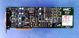
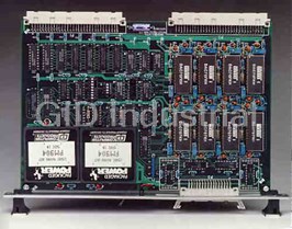
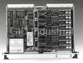
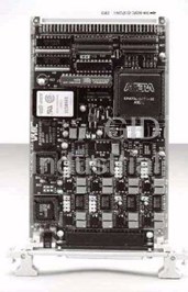
VMIC VMIVME-4105 8-Channel 12-Bit Multiplying Digital-to-Analog Converter Board
Part Number
VMIVME-4105
Price
Request Quote
Manufacturer
VMIC
Lead Time
Request Quote
Category
ANALOG OUTPUT BOARDS
Features
- ±10 V or 0 to -10 V jumper-selectable options
- 12-bit resolution
- 2- or 4-quadrant multiplier jumper-selectable option
- 8-channel analog output (D/A per channel)
- Double Eurocard format with front panel fail LED
- Internal DC reference to support Built-in-Test
- Jumper option to support eight independent or one shared AC or DC voltage reference
- Jumper-selectable P2 or front panel outputs
- Multiplexed programmable outputs for testing analog outputs
- Requires VMIVME-31xx for Built-in-Test
Datasheet

Extracted Text
VMIVME-4105 8-Channel 12-bit Multiplying Digital-to-Analog Converter Board • 8-channel analog output (D/A per channel) • Jumper-selectable P2 or front panel outputs • 12-bit resolution • 2- or 4-quadrant multiplier jumper-selectable option • Jumper option to support eight independent or one shared AC or DC voltage reference • ±10 V or 0 to -10 V jumper-selectable options • Double Eurocard format with front panel fail LED • Requires VMIVME-31xx for Built-in-Test • Multiplexed programmable outputs for testing analog outputs • Internal DC reference to support Built-in-Test FUNCTIONAL CHARACTERISTICS Analog Output Channels: Eight multiplying analog output channels. For unipolar operation (two-quadrant multiplier), the analog output equation is: V = -V (Digital Code ) OUT REF 10 4,096 Analog Output Testing: Any one of the eight analog outputs may be switched to the analog output test bus The analog output equation for offset binary bipolar (Test Bus 2). This bus is routed through the P2 AMXbus operation (four-quadrant multiplier) is: analog backplane to an Analog-to-Digital Converter (ADC) board which is used to verify each DAC channel on the VMIVME-4105 board. V = -V + V (Digital Code ) x2 OUT REF REF 10 4,096 Compatibility: The VMIVME-4105 Analog Output Board is a standard, double height, printed circuit board Analog outputs are jumper selectable to the P2 or P3 which is compatible with the VMEbus speciŢcation. connector. Board Address: The physical address for the board Test Mode: The DAC board may be used in may be selected through a 12-bit DIP switch. VMEbus conjunction with other VMIC boards and the VMIC address lines A04 through A15 are decoded for board AMXbus™ backplane for extensive fault detection and selection. isolation. There are two dedicated analog buses that are used by the DAC board. Tests may be performed by utilizing any one of the eight Ordering Options DAC outputs. While in a test mode the eight DAC October 9, 1995 800-004105-000 G ABC – D E F outputs may be isolated from the P3 connector so that user-connected devices are not affected by worst-case VMIVME-4105 –0 0 – testing in an off-line mode. Real-time fault detection and A = 0 (Option reserved for future use) B = Channel/Built-in-Test Options isolation is not supported if the multiplying DAC option 1 = 4-Channel, 12-bit Multiplying Analog Outputs without is used. Built-in-Test is not supported if P2 outputs are Built-in-Test 2 = 8-Channel, 12-bit Multiplying Analog Outputs without used. Built-in-Test 3 = 8-Channel, 12-bit Multiplying Analog Outputs with Built-in-Test C = 0 (Option reserved for future use) Analog Input Test Mode: Any one of the eight analog Connector Data outputs may be switched to an analog test bus Compatible Cable Connector Panduit No. 120-332-435E (Test Bus 1). This analog bus may be used to verify the Strain Relief Panduit No. 100-000-042 PC Board Header Connector Panduit No. 120-332-033A operation of a VMIC Multiplexer Expansion Board For Ordering Information, Call: (VMIVME-3200A) that is designed to support 1-800-322-3616 or 1-256-880-0444 • FAX (256) 882-0859 Built-in-Test. The interconnecting of the analog bus E-mail: info@vmic.com Web Address: www.vmic.com Copyright © March 1986 by VMIC between boards may be accomplished by using one of Specifications subject to change without notice. VMIC’s 5-, 9-, or 19-slot AMXbus backplanes. VMIC ¥ 12090 South Memorial Parkway ¥ Huntsville, Alabama 35803-3308 1 VMIVME-4105 VMEbus Access: Address modiŢer bits are decoded to Front Panel Fail LED: If an error condition is detected, support nonprivileged short I/O or supervisory short I/O a front panel Fail LED may be illuminated under access. A single jumper is provided to support the option. software control for a visual failure indication. The Fail LED is illuminated upon power up clear and is extinguished upon successful diagnostic execution. Data Transfer: When a board write operation is executed, the destination of the data is controlled by data bit 15. If data bit 15 is a one, the word is written to the DAC Reference: All eight DAC channels may share a Control Register. When data bit 15 is a zero, the data is high precision, low drift, reference that is buffered and written to the Digital-to-Analog Converter (DAC) that is available for external use at the P2 connector. A addressed. Executing a read access to any valid board user-supplied reference may be selected for the reference address will allow the user to read the board status. for eight DAC channels. This reference may be input to Digital data to the DAC is contained in data bits D00 the board by either the P2 or P3 connector. An individual through D11. Unipolar binary code is used for unipolar reference per channel is available through the P2 operation (0 to -10 V output). Bipolar operation (-10 to connector which provides the capability for eight +10 V output) may use either offset binary or two’s independent multiplying analog output channels. complement code. ELECTRICAL CHARACTERISTICS Mode Selection: The operation modes of the board Data Transfer: A16/D16 may be selected by writing to the Control Register. Only data bits D08 through D14 are utilized for the Control Analog Output (Voltage Output @ R = 2 kW Register. Data bits D08 through D14 contain information LOAD and V = +10 V): to select the different DAC operation modes. The REF Unipolar: 0 to -10 V function of each bit is as follows: Bipolar: -10 to +10 V at 5 mA D08 – Enables DAC outputs to the P3 DAC Input Code: connector Unipolar: Unipolar binary code D09 – Selects internal +10 V reference or Bipolar: Offset binary or two’s complement code external user-supplied reference D10 to D13 – Test mode control bits Resolution: 12 bits D14 – Operates Fail LED D15 – Routes data to the Control and Status * Accuracy at (25 °C): Register (CSR) Gain Error: Adjusted to ±1/2 LSB (if D15 = one) or to selected Offset: ±0.5 mV DAC channel (if D15 = zero) Relative Accuracy: ±1 LSB Note the CSR can be accessed from any of the Gain Temperature CoefŢcient: eight-word locations. ±10 PPM/°C D Gain/ D Temperature When the board is written to, the destination of the data is controlled by data bit 15. If data bit 15 is a one, the word is written to the Control Register. When data bit 15 * Accuracy stated without analog output isolation switches is a zero the data is written to the DAC which is installed. The Built-in-Test hardware features analog output addressed. Executing a read access to any valid board isolation switches for all eight channels. These switches are in address will allow the user to read the board status. series with the analog output and the user-connected device at the P3 connector and may be switched under software control. These switches have an ON resistance of approximately System Reset: Application of the system reset signal 100 W (maximum). If the user-connected load does not have through the VMEbus initializes the board into a state a high impedance input, then a possible voltage division error with all analog outputs disconnected from the output is introduced. For example, if R(LOAD) is 10 kW, then a 1 connector (P3) and the analog test outputs disconnected percent error is introduced. R(LOAD) should be 1 MW or from the P2 connector. greater for an error of .01 percent or less. . 2 For Ordering Information, Call: 1-800-322-3616 or 1-256-880-0444 ¥ FAX (256) 882-0859 VMIVME-4105 External DAC Reference Input: Humidity: 20 to 80 percent relative, noncondensing ±10 VDC input (maximum) ±10 V p-p AC input (maximum) Altitude: Operation to 10,000 ft Output Accuracy Versus Frequency Cooling: Forced air convection (AC Reference Input Sine Wave): Dimensions: Double Eurocard (6U) 1 percent of FSR up to 10 kHz 160 x 233.35 mm Reference Output: VMEbus Connector: Two 96-pin DIN connectors. Voltage Output: 0 V (±0.5 mV) VMIC utilizes the user I/O pins on the P2 connector to Temperature CoefŢcient: 5 PPM/°C support an optional analog bus (AMXbus). A wide Long-Term Stability: 25 PPM/1,000 hr variety of AMXbus backplanes are available from VMIC Current Available for External Use: 10 mA as a standard product. 1 Output Connector: Settling Time: 6 µs (maximum) to ± / LSB 2 Board Connector (P3) — Panduit male connector type 120-332-033A Monotonicity: Monotonic over full temperature range Input cable connector — female type 120-332-435E Output Isolation Resistance: Power Requirement: 2.5 A (maximum) at +5 VDC Resistance of output switch — 100 W (maximum) Field isolation switches are optional TRADEMARKS PHYSICAL/ENVIRONMENTAL AMXbus is a trademark and the VMIC logo is a registered trademark of VMIC. Other registered trademarks Temperature: 0 to +55 °C, operating are the property of their respective owners. -20 to +85 °C, storage APPLICATION AND CONFIGURATION GUIDES — The following Application and ConŢguration Guides are available to assist the user in conŢguring systems based on VMIC’s products: Title Document No. Digital Input Board Application Guide 825-000000-000 Change-of-State Board Application Guide 825-000000-002 Digital I/O (with Built-in-Test) Product Line Description 825-000000-003 Synchro/Resolver (Built-in-Test) Subsystem ConŢguration Guide 825-000000-004 Analog I/O Products (with Built-in-Test) ConŢguration Guide 825-000000-005 Connector and I/O ConŢguration Guide 825-000000-006 VMIC ¥ 12090 South Memorial Parkway ¥ Huntsville, Alabama 35803-3308 3 VMIVME-4105 INTERNAL REFERENCE V00 DAC0 AN00 ER1 REFERENCE SELECTION DAC1 V01 ER8 DAC2 V02 VMEbus DAC3 V03 P2 or P3 V00 AN00 C O ANALOG OUT M ISOLATION P V L V07 A SWITCHES DAC7 M O AN07 T V07 E G I b I B u ADDRESS C I BUS s L I TEST MODE T (TM) Y ADDRESS REGISTER A0 TEST DUAL TO AMXbus™ SPDT BACKPLANE SWITCH A0IN TEST A0 TEST CONTROL CONTROL STATUS STATUS REG REG V07 V00 SELECT AIN TEST (SAIT) SELECT A0 TEST (SA0T) 4 8-CH MUX A OUT ADDR SELECT Figure 1. VMIVME-4105 8-Channel Multiplying Analog Output Board AIN0 • • • ON-BOARD ANALOG INPUTS • VMIC 32XX SERIES EXPANSION • • MULTIPLEXERS AINn EXPANDED ANALOG INPUTS EXPANDED ANALOG INPUTS CONV. COMP. ADC ANALOG OUTPUT TEST AN00 ANALOG • OUTPUT • BOARD • PRECISION AN07 VOLTAGE SELF- TEST INPUTS • VMIVME-4105 • • ADC AN00 ANALOG • OUTPUT • BOARD • VMIVME-31XX AN07 EXTERNAL START CONVERSION OPTION Figure 2. Simplified Functional Multiplying DAC Subsystem Configuration with Built-in-Test 4 For Ordering Information, Call: 1-800-322-3616 or 1-256-880-0444 ¥ FAX (256) 882-0859
Frequently asked questions
What makes Elite.Parts unique?

What kind of warranty will the VMIVME-4105 have?
Which carriers does Elite.Parts work with?
Will Elite.Parts sell to me even though I live outside the USA?
I have a preferred payment method. Will Elite.Parts accept it?


What they say about us
FANTASTIC RESOURCE
One of our top priorities is maintaining our business with precision, and we are constantly looking for affiliates that can help us achieve our goal. With the aid of GID Industrial, our obsolete product management has never been more efficient. They have been a great resource to our company, and have quickly become a go-to supplier on our list!
Bucher Emhart Glass
EXCELLENT SERVICE
With our strict fundamentals and high expectations, we were surprised when we came across GID Industrial and their competitive pricing. When we approached them with our issue, they were incredibly confident in being able to provide us with a seamless solution at the best price for us. GID Industrial quickly understood our needs and provided us with excellent service, as well as fully tested product to ensure what we received would be the right fit for our company.
Fuji
HARD TO FIND A BETTER PROVIDER
Our company provides services to aid in the manufacture of technological products, such as semiconductors and flat panel displays, and often searching for distributors of obsolete product we require can waste time and money. Finding GID Industrial proved to be a great asset to our company, with cost effective solutions and superior knowledge on all of their materials, it’d be hard to find a better provider of obsolete or hard to find products.
Applied Materials
CONSISTENTLY DELIVERS QUALITY SOLUTIONS
Over the years, the equipment used in our company becomes discontinued, but they’re still of great use to us and our customers. Once these products are no longer available through the manufacturer, finding a reliable, quick supplier is a necessity, and luckily for us, GID Industrial has provided the most trustworthy, quality solutions to our obsolete component needs.
Nidec Vamco
TERRIFIC RESOURCE
This company has been a terrific help to us (I work for Trican Well Service) in sourcing the Micron Ram Memory we needed for our Siemens computers. Great service! And great pricing! I know when the product is shipping and when it will arrive, all the way through the ordering process.
Trican Well Service
GO TO SOURCE
When I can't find an obsolete part, I first call GID and they'll come up with my parts every time. Great customer service and follow up as well. Scott emails me from time to time to touch base and see if we're having trouble finding something.....which is often with our 25 yr old equipment.
ConAgra Foods