

 Manufacturers
VMIC VMIVME-3123
Description
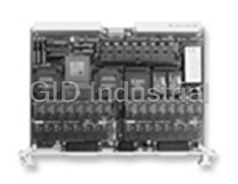
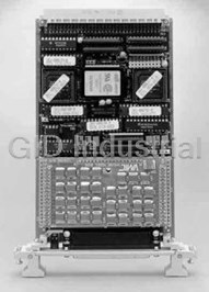
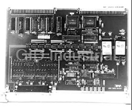
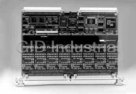
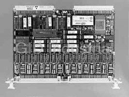
VMIC VMIVME-3123 16-bit High Throughput Analog Input Board 16 Channels with Simultaneous Sample-and-Hold Inputs
Part Number
VMIVME-3123
Price
Request Quote
Manufacturer
VMIC
Lead Time
Request Quote
Category
ANALOG INPUT BOARDS
Features
- 16 Channels with Simultaneous Sample-and-Hold Inputs
- 16 differential analog input channels
- 16-bit A/D converters: one per channel
- 16-bit High Throughput Analog Input Board
- Built-in-Test
- Digital calibration: no channel trimmers
- High throughput with channel pairing
- internal references applied to channel inputs: all active devices tested
- or 16 active channels
- Simultaneous sample-and-hold inputs
Datasheet

Extracted Text
GE Fanuc Automation VMIVME-3123 Specifications 16-bit High Throughput Analog Input Board 16 Channels with Simultaneous Sample-and-Hold Inputs Features: • Continuous sampling mode • 16 differential analog input channels • Software-selectable as 1, 2, 4, 8, or 16 active channels • Triggering capabilities — Internal, external, VME host triggering, or multiboard • 16-bit A/D converters; one per channel synchronous • Simultaneous sample-and-hold inputs • ±10V, ±5V input ranges with bipolar option and +10V, +5V • High throughput input ranges with true unipolar option — 1,600 kHz aggregate sample rate • Selectable delay — 100 kHz per channel; 200 kHz with channel pairing • Low pass filters for antialiasing • Digital calibration; no channel trimmers • Interrupter • Built-in-Test; internal references applied to channel inputs; all active devices tested • Large data buffer; up to 4 million data samples Applications: • Transient capture mode triggering on input signal • Precision voltage monitoring • Data acquisition systems • Control systems • Automatic test equipment (ATE) • Trainers and simulators VMIVME-3123 16-bit High Throughput Analog Input Board with 16 Channels with Simultaneous Sample-and-Hold Inputs performed at any time without removing the board from the Ordering Options system. Calibration uses internal precision voltages (a built-in- August 10, 2007 800-003123-000 N test feature) applied to all input channels to determine the A B C D E F correction values. A test mode as well as the host have access VMIVME-3123 – 0 0 to the voltages for BIT purposes. A = Bipolar Input Option 0 = Reserved Compliance: This board complies with the VMEbus specification 1 = Bipolar (±10 and ±5V Input Ranges) (ANSI/IEEE 1014-1987 IEC 821 and 297) with the following 2 = Unipolar (+10 and +5V Input Ranges) mnemonics: B = Low Pass Filter Type and Frequency 0 = No Filter Addressing: A32, A24, A16 1 = Bessel, 240Hz Address Modifiers: 0F, 0D, 0B, 09, 3F, 3D, 3B, 39, 2D, 29 2 = Bessel, 2.4kHz Data Transfers: D32: D16: D08 (EO): D08 (0): BLT 3 = Bessel, 24kHz Control Register Transfers: 4 = Butterworth, 240Hz 5 = Butterworth, 2.4kHz Hardware Registers: D16, D08 EO) 6 = Butterworth, 24kHz Firmware Registers: D16 (WRITE) C = Input Channels and Data Buffer Size D16, D08 (EO) (READ) 0 = 16 Channels/4 Megasamples Interrupts: I(1) to I(7) ROAK, with D08 (0) vector 1 = 16 Channels/1 Megasample Form Factor: 6U 2 = 8 Channels/4 Megasamples 3 = 8 Channels/1 Megasample Board Address: The physical base address for the board’s data D = 0 (Reserved for future options) buffer is software selected by onboard registers in short I/O E = 0 (Reserved for future options) F = Conformal Coating space. The standard and extended windows into the data buffer 0 = No Conformal Coating can be enabled/disabled through registers in short I/O space. 1 = With Conformal Coating Example VME Access: Address modifier bits are enabled in short I/O registers and decoded to support both nonprivileged, A part number VMIVME-3123-140 specifies a 16-channel VMIVME-3123 supervisory, or both access modes. board with 4 megasample data buffer, bipolar input ranges, and 240 Hz Butterworth low pass filter. Data Transfers: Conversion data is retrieved from the data I/O Connector Data buffer through the memory-mapped data space, commencing Style Recommended P3 and P4 with the first conversion sample and proceeding in sequence Connecting Component I/O Connector through the last sample in the buffer. 25-pin Mating Connector AMP 747912-2 Discrete Wire 25-pin D-Subminiature Built-in-Test: Precision internal reference voltages can be Discrete Wire Using Solder Cups substituted for the field inputs at all channels simultaneously. Connector Shell Housing AMP 748042-1 9-pin Mating Connector AMP 747904-2 System Reset: After a system reset occurs, the board enters an Discrete Wire 25-pin D-Subminiature IDLE operating mode in which the board sample clock is chosen Discrete Wire Using Solder Cups as the sampling source, and the buffer sizes are maximized with Connector Shell Housing AMP 748038-1 all channels enabled. The board does not acquire data in IDLE For Ordering Information, Call: mode. The front panel LED indicator is turned ON at reset. 1-800-322-3616 or 1-256-880-0444 • FAX (256) 882-0859 Email: info.embeddedsystems@gefanuc.com Calibration: This board calibrates itself under host control and Web Address: www.gefanucembedded.com then uses the gain and offset coefficients during signal Copyright © 2007 by GE Fanuc Embedded Systems acquisition. This eliminates the need for gain and offset trim Specifications subject to change without notice. potentiometers, and provides a software solution to calibrating the board. Calibration is performed when the host changes the Functional Characteristics operating mode to CAL and consists of routing precision reference voltages to the channel inputs, reading the associated Introduction: The VMIVME-3123 analog input board provides 16 16-bit analog-to-digital converter (ADC), determining the gain high accuracy differential analog input channels with high and offset coefficients, and storing them in onboard volatile throughput 16-bit analog-to-digital (A/D) conversion rates to 1.6 memory. During data acquisition, the A/D data in a particular million samples per second. Each input is equipped with a channel is multiplied by the gain coefficient and added to the dedicated sample-and-hold amplifier, a fourth-order offset coefficient. This corrected data is then written to the data antialiasing filter, and a precision 16-bit A/D converter. buffer. Digitized samples are accumulated in a data buffer until Note: Calibration is under host control and does not occur retrieved by the system. Buffer size is software controlled from during powerup. one sample to 4 million samples. Accuracy is optimized with the use of correction values for gain and offset that are applied in real-time, and determined during a host-controlled calibration mode. Calibration can be 2 VMIVME-3123 16-bit High Throughput Analog Input Board with 16 Channels with Simultaneous Sample-and-Hold Inputs Internal Bit References: ±9.9800VDC, ±4.99VDC ±0.003 percent Electrical Characteristics ±3PPM/°C ±0.002 percent/year (Specified at +25 °C and rated supplies, unless otherwise noted.) Bandwidth: DC to specified filter frequency. The No Filter option Analog Inputs: provides a minimum bandwidth of DC to 400kHz. Input Configuration: Sixteen differential input channels, with Large Signal Bandwidth: 1kHz (no filter) with 10V peak dedicated sample-and-hold per channel. Optional 8-channel configuration available; see the Ordering Options. Small Signal Bandwidth: 40kHz (no filter) 1V pk-pk A/D Converters: 16-bit A/D converter per channel Low Pass Input Filters: Fourth-order low pass filters with corner frequencies of 240Hz, 2.4kHz, or 24kHz, ±25 percent. Available Voltage Ranges: ±5 and ±10V full scale, software-selectable with Bessel or Butterworth response. (See the Ordering Options.) 1 Offset Voltage and Drift: ±2.7µV, ±5µV/°C RTI Access and Cycle Times Bias Current and Drift: ±55 ±1 nA/°C Access Time: Time (DSA* to DTACK*) Common-Mode Voltage (CMV): Cycle Time: Time (DSA* to DSA*) (VCM + (VDIFF/2)(G)): ±12V Hardware Registers: 250ns Access Time Common-Mode Rejection Ratio (CMRR): 95dB typical, 85dB minimum DC to 60Hz with 350 ¾ source unbalance Firmware Resisters: 3.5µs Access Time (maximum), 2.5µs (typical) Noise: 1,000µVRMS, RTI at 240Hz 1,000µVRMS, RTI at 2,400Hz Note: Firmware registers are used for nonreal-time operations 1,000µVRMS, RTI at 24kHz and are available only during IDLE mode. 1,300µVRMS, RTI at No Filter Non-BLT DRAM Memory: 380ns Access Time, 750ns Cycle Time Overvoltage: Protected to ±40V sustained, ±100V for one second BLT DRAM Read Access: Crosstalk: 96dB maximum, DC to 1kHz : 1st Transfer - 360ns Access Time, 640ns Cycle Time 2nd - 256th Transfer - 100ns Access Time, 260ns Cycle Time Transfer Characteristics (±10V FSR) Note: The VME must compete with refresh operations and input Resolution: 16-bit (305µV/LSB) data deposits through arbitration for control of the DRAM. Gain Accuracy: ±0.005 percent ±21 PPM/°C ±0.005 percent/year Refresh operations occur at 16µs intervals and hold the DRAM after calibration to internal references. Drift errors can be for 300ns. A 16-channel burst of analog input data will occupy removed with recalibration. the DRAM for 1.5µs (two bursts of 750ns each) and occurs at the host-selected sampling rate during modes when the board is Integral Nonlinearity: ±0.0053 percent digitizing data. The VME has the lowest priority. Differential Nonlinearity: ±0.0053 percent Control Sampling Rate: 1,600 KSPS (thousand samples per second) maximum aggregate rate. Per-channel rate software controlled Sample Clock: All active inputs are sampled (that is, enter Hold from 381 to 100,000 SPS. The per-channel rate can be doubled sample mode) simultaneously in response to sampling clock to 200,000 SPS by pairing input channels (0 and 8, 1 and 9, etc.) which is controlled by three control bits in a control register. when using a 16-channel board with a net reduction in available Internal: Onboard timer generates a periodic clock at software- channels. selectable rates from 381 to 100,000 samples per second Sampling Delay: Internal clock - 40ns (typical), (clocks per second); to 200,000 CPS on a 16-channel board with 2 External clock - 70ns (typical), Multiboard - 100ns (typical) channel pairing . Board-to-board sample time difference - 50ns maximum I/O Sample Clock: Clock is generated by setting a control Sampling Jitter: 0 to 3ns (0 to 15ns if channel pairing is used to register bit. achieve a 200 KSPS per channel sample rate) External Master: A front panel TTL-level input is available as an Data Latency: The user should note the data deposited into external clock. It can be software selected to generate a DRAM from the analog section will correspond to the (n-1) conversion on either the rising or falling edge. Front panel sample. When a sample pulse is generated, the ADC converts multiboard sample clock signals are used to synchronize the sampled analog input and simultaneously transmits the multiple boards. Multiple boards will be sampled within 100ns of previously converted sample to the Digital Signal Processor to the external master clock and within 50ns of each other. correct and place in DRAM. The latency from the sample pulse to the availability of the n-1 sample will be less than 20µs. 2 Channel pairing is implemented by (a.) wiring input channels together in groups of two and (b.) by selecting the 2x mode, which effectively doubles the per-channel sample rate. The channel pairing option is only available on 1 RTI = Referred to inputs. the 16-channel board. 3 VMIVME-3123 16-bit High Throughput Analog Input Board with 16 Channels with Simultaneous Sample-and-Hold Inputs External Slave: Front panel multiboard sample clock inputs In all sample clock modes other than the internal mode, the allow the VMIVME-3123 to be set up as a slave and clocked in sampling rate is controlled from zero to 200,000 SPS by external tandem with a master board. The slave boards will be sampled clock sources. within 100ns of the external master clock and within 50ns of Buffer Flag Control: Two interrupt control bits (A and B) can be each other. Up to two slave boards may be used as slaves in used by the host to determine when the data buffer is 50 or 100 tandem with a master board. percent filled. The interrupt request can be enabled for interrupt 2x: (Channel Pairing): Provides alternate clocking of upper and operation or disabled, and the A and B status bits polled by the lower 8 channels to support channel pairing (16-channel board host. only). Available for internal timer and external master clocks. Physical/Environmental Operational Modes: The board uses five modes to perform a Dimensions: Standard VME double height board (160 x 233.5 variety of tasks. They are listed as follows: mm) Idle: Host initialization Weight (Mass): 0.7kgm maximum Burst: Used for capturing transient waveforms, uses triggers Continuous Sample: Continuous data stream that does not use Temperature: 0 to 65 °C, operating, -25 to +85 °C, storage triggers. Relative Humidity: 20 to 80 percent, noncondensing Calibration: Determines correction coefficients Test: Performs self-test on analog input section and DRAMs Cooling: Normal VME chassis forced air circulation Trigger: Two bits in a control register determine the starting Power Requirements: +5VDC (+5/-2.5 percent) at 5.0A point for the data in the buffer when using burst mode. The maximum buffer is continuously filled and the trigger marks the starting address for the desired position in the data buffer. The position Altitude: Operation to 3,000m of the trigger is user selected to be at the beginning, end, or MTBF: 63,000 hours (217F) middle of the buffer. The trigger is not to be used in continuous sample mode. Trademarks Built-in-Test: Three control bits are used to select one of the All registered trademarks are the property of their respective following inputs to all channels: owners. Normal field inputs +9.9800VDC -9.9800VDC +4.9900VDC -4.9900VDC Zero Calibration: A board calibration sequence is performed upon host command. The calibration constants are accessible by the VME. Calibration elapsed time is approximately 8s. Front Panel Indicator: A single control bit turns the front panel LED indicator ON or OFF. The indicator is turned ON automatically after any RESET operation. CSR Reset: The board uses two bits in a hardware control register to perform hardware reset and Halt functions. Active Channels: The active channels are selected by setting the corresponding bit in a 16-bit channel enable register. The host may enable channels in groups of 1, 2, 4, 8, or 16 active channels. The channels may be selected in any combination as long as the aforementioned groupings are adhered to. (An active channel is one which is digitized and stored in the data buffer.) Buffer Size: Five control bits configure the data buffer size from one data sample to 4 million samples. Sampling Rate: In the Internal Sample Clock Mode, fourteen bits control the sampling rate from 381 to 100,000 SPS (200,000 SPS available with channel pairing on the 16-channel board only). 4 VMIVME-3123 16-bit High Throughput Analog Input Board with 16 Channels with Simultaneous Sample-and-Hold Inputs Figure 1. VMIVME-3123 Functional Block Diagram GE Fanuc Embedded Systems Information Centers Additional Resources Americas: For more information, please visit the Huntsville, AL 1 800 322-3616 GE Fanuc Embedded Systems web site at: 1 (256) 880-0444 www.gefanucembedded.com Camarillo, CA 1 (805) 987-9300 Greenville, SC 1 (864) 627-8800 Richardson, TX 1 (972) 671-1972 Europe, Middle East and Africa: Edinburgh, UK 44 (131) 561-3520 Paris, France 33 (1) 4324 6007 5
Frequently asked questions
What makes Elite.Parts unique?

What kind of warranty will the VMIVME-3123 have?
Which carriers does Elite.Parts work with?
Will Elite.Parts sell to me even though I live outside the USA?
I have a preferred payment method. Will Elite.Parts accept it?


What they say about us
FANTASTIC RESOURCE
One of our top priorities is maintaining our business with precision, and we are constantly looking for affiliates that can help us achieve our goal. With the aid of GID Industrial, our obsolete product management has never been more efficient. They have been a great resource to our company, and have quickly become a go-to supplier on our list!
Bucher Emhart Glass
EXCELLENT SERVICE
With our strict fundamentals and high expectations, we were surprised when we came across GID Industrial and their competitive pricing. When we approached them with our issue, they were incredibly confident in being able to provide us with a seamless solution at the best price for us. GID Industrial quickly understood our needs and provided us with excellent service, as well as fully tested product to ensure what we received would be the right fit for our company.
Fuji
HARD TO FIND A BETTER PROVIDER
Our company provides services to aid in the manufacture of technological products, such as semiconductors and flat panel displays, and often searching for distributors of obsolete product we require can waste time and money. Finding GID Industrial proved to be a great asset to our company, with cost effective solutions and superior knowledge on all of their materials, it’d be hard to find a better provider of obsolete or hard to find products.
Applied Materials
CONSISTENTLY DELIVERS QUALITY SOLUTIONS
Over the years, the equipment used in our company becomes discontinued, but they’re still of great use to us and our customers. Once these products are no longer available through the manufacturer, finding a reliable, quick supplier is a necessity, and luckily for us, GID Industrial has provided the most trustworthy, quality solutions to our obsolete component needs.
Nidec Vamco
TERRIFIC RESOURCE
This company has been a terrific help to us (I work for Trican Well Service) in sourcing the Micron Ram Memory we needed for our Siemens computers. Great service! And great pricing! I know when the product is shipping and when it will arrive, all the way through the ordering process.
Trican Well Service
GO TO SOURCE
When I can't find an obsolete part, I first call GID and they'll come up with my parts every time. Great customer service and follow up as well. Scott emails me from time to time to touch base and see if we're having trouble finding something.....which is often with our 25 yr old equipment.
ConAgra Foods