

 Manufacturers
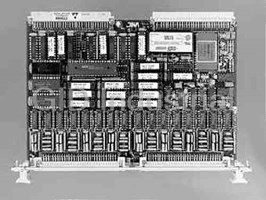
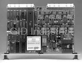
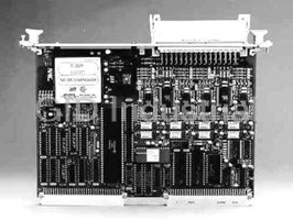
VMIC VMIVME-3113A
Description
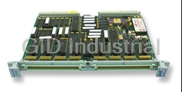
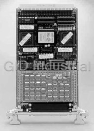
VMIC VMIVME-3113A Scanning 12-bit Analog-to-Digital Converter Board with Built-in-Test
Part Number
VMIVME-3113A
Price
Request Quote
Manufacturer
VMIC
Lead Time
Request Quote
Category
ANALOG INPUT BOARDS
Datasheet

Extracted Text
GE Fanuc Automation VMIVME-3113A Specifications Scanning 12-bit Analog-to-Digital Converter Board with Built-in-Test Features: • Jumper-programmable gain 1, 10, 100, 200, and 500 • 64 differential or single-ended inputs • Selectable A/D ranges of 0 to +10V , ±5V, and ±10V • Powers up in autoscanning mode — no software initialization • Low-level and high-level inputs: ±10mV to ±10V required • Optional low pass filter (the VMIVME-3113A has improved • Continually digitizes input channels and stores the results in a high-frequency rejection characteristics) dedicated channel dual-port register (autoscanning mode) • Overvoltage protected inputs • Jumper-selectable scanning of 2 to 64 channels 6 • 5 x 10Ω input impedance • Supports real-time and off-line Built-in-Test • 33 kHz conversion rate • Five operating modes plus test mode • Selectable output code: binary, offset binary, two’s — Autoscanning mode (gain=1) complement with sign extension — Random poll mode • Applications — Random interrupt mode — Factory automation and instrumentation — Scanning poll mode — Process control — Scanning interrupt mode — Laboratory instrumentation • VMEbus interrupts may be programmed to interrupt upon — Machine monitoring completion of a single A/D conversion or upon completion of — Data acquisition a 2- through 64-channel scan • User-programmable interval timer supports scanning of all channels at periodic intervals VMIVME-3113A Scanning 12-bit Analog-to-Digital Converter Board with Built-in-Test A jumper-selectable, Programmable Gain Amplifier supports Ordering Options gain ranges of 1, 10, 100, 200, and 500. A/D conversion time is July 7, 2006 800-103113-000 C 15μs. A wide variety of low pass filters are supported. A B C D E F 0 0 0 0 VMIVME-3113A – A functional block diagram is provided in Figure 1 in on page 5 of this specification. A = Input Filter Options 0 = No Filter 1 = 40 Hz (3 dB Cutoff Frequency) Operating Modes BCDE = 0 (Options reserved for future use) Autoscanning Mode: The mode is executed by a powerup F = Conformal Coating 0 = Standard VME front panel without conformal coating system reset or program selection. All channels are 1 = Reserved continuously scanned and the digitized data is stored in 64, 2 = Standard VME front panel with conformal coating 16-bit dual-port registers. No other programming is required to start the A/D conversion process. The user has only to read the Connector Data digitized data from the dual-port register of the desired Style Recommended P3 and P4 channel. This mode is for gains of 1 only and for a minimum of Connecting Component I/O Connectors 16 connected channels. 64-pin IDC Mating Connector Panduit 120-964-435E (64-pin) Strain Relief Panduit 100-000-032 Random Polling Mode: This mode requires the controlling (for 64-pin Connectors) program to generate a single conversion. End-of-conversion is Mating Connector AMP 925486-1 determined by polling an end-of-conversion status bit. 96-pin (96-pin Discrete) AMP 530151-6* Discrete Female Crimp Contacts Random Interrupt Mode: This is the same as Random Poll Wire (96-pin Discrete) Mode except end-of-conversion generates an interrupt to the Connector Housing Hurting CPU board. (For 96-pin Connectors) 09 03 096 0501 Mating Connector ERNI 913.031 Scanning Poll Mode: This is a scanning mode which executes a 96-pin (96-pin Mass Terminated) single scan of all channels. An end-of-scan control bit is polled IDC 0.033-inch Ribbon Cable ERNI 913.049 to determine when the scan is completed. (96-pin Mass Terminated) Strain Relief Insert Harting Scanning Interrupt Mode: This is a scanning mode which (0.033-inch Ribbon Cable) 09 02 000 9912 executes a single scan of all channels and generates an Connector Housing Harting end-of-scan interrupt when the scan is completed. (For 96-pin Connectors) 09 03 096 0501 PC Board I/O Connector Part Number Panduit 101-096-033A Autoscanning Bit Mode: All channels continuously scanned *AMP crimp tool part number 90301-2. with channel 0 muxing in one of three precision reference For Ordering Information, Call: voltages. The voltages are 4.980, 0.4928, and 0.009915V. 1-800-322-3616 or 1-256-880-0444 • FAX (256) 882-0859 Email: info.embeddedsystems@gefanuc.com Programmable Interval Timer: A triple, 16-bit timer (may be Web Address: www.gefanuc.com/embedded cascaded to 48 bits) is programmable to generate a periodic Copyright © 2006 by GE Fanuc Embedded Systems trigger to start an A/D scan. Specifications subject to change without notice. External Trigger: A user-connected signal may be used to start a scan. Functional Characteristics Programmable Gain Amplifier: A jumper Programmable Gain Amplifier supports conversions of low-level inputs Introduction: This product is designed to support 64 channels of (from ±10mV to ±10V full scale). differential or single-ended wide range (±10mV to ±10V) analog inputs. End-of-Conversion/Scan Interrupts: The Scanning Interrupt Mode and the Random Scanning Mode generate an The board supports the following operating modes which are end-of-conversion or end-of-scan interrupt, respectively. All described below: VMEbus interrupt levels 1 to 7 are supported through a Autoscanning user-programmable on-board Bus Interrupter Module (BIM). Random Polling Compatibility: The ADC board is a standard double height Random Interrupt printed circuit board which is compatible with the VMEbus Scanning Poll specification (Rev. C.1). Scanning Interrupt Autoscanning with BIT Board Address: The physical address for the board may be selected by on-board jumpers. VMEbus address lines A08 A 64-word dual-port provides storage for a continuous scan of through A15 are decoded for board selection. The board all channels. The scanning modes are executed automatically at occupies 256 bytes in the short I/O address space. powerup, system reset, or are entered under program control. The dual-port registers allow VMEbus access at any time to read the latest stored data. 2 VMIVME-3113A Scanning 12-bit Analog-to-Digital Converter Board with Built-in-Test Address Modifier: Address modifier bits are jumper-selected Accuracy and decoded to support either nonprivileged short I/O, Instrumentation Amp Nonlinearity, DC: supervisory short I/O, or both. The board is factory configured G = 1 ±0.001 percent FSR for supervisory short I/O. G = 10 ±0.002 percent FSR Analog Input Format: Analog inputs are digitized and stored in G = 100 ±0.004 percent FSR 64 dual-port registers as a 12-bit digital value (D11 to D00) G = 200 ±0.006 percent FSR which may be read by the user. Selectable data codes are G = 500 ±0.01 percent FSR binary, offset binary, and two’s complement. The sign is System Accuracy (Including Linearity Error): extended to the upper four bits (D12, D13, D14, and D15). G = 1 0.035 percent FSR System Reset: System reset automatically places the board in G = 500 0.075 percent FSR the Autoscanning Mode. Stability (Over Temperature) Front Panel Diagnostic LED: A software-controlled LED may be Instrumentation Amp Drift: extinguished upon successful completion of diagnostics. The ±(2.0 + 20/G) μV/°C LED is illuminated by system reset. System Accuracy Drift: Electrical Specifications G = 1 5 PPM/°C (Typical at +25°C and rated power supplies unless otherwise G = 500 50 PPM/°C stated.) Bus Interface Input Characteristics Compatibility: VMEbus A16: D16 Number of Input Channels: 64 differential or 64 single-ended Interrupt: IRQ1 through IRQ7 Full-Scale A/D Input Ranges: ±5V, ±10V, and 0 to +10V Interrupter Release: ROAK (Release-on-Acknowledge) Amplifier Gain Ranges: 1, 10, 100, 200, and 500 Jumper-programmable Physical/Environmental Specifications Dimensions: Standard VME double height board Full-Scale Input Range: ±10mV to ±10V 160 x 233.5mm 6 6 Input Impedance: 5 x 10Ω differential. 2 x 10Ω Power Requirements: +5VDC (±5 percent) at 2.5A maximum single-ended Temperature: Operating: 0 to 55° C Common-Mode Voltage (Maximum): Storage: -25 to +85° C ±11V (V + V /2)*gain) CM diff Altitude: Input Overvoltage Protection: ±40V, maximum Operating: 0 – 10,000 ft (3,000m) Optional Single-Pole Analog Input Filter: -3 dB at 40 Hz Storage: 0 – 40,000 ft (12,000m) Humidity: Transfer Characteristics Operating: relative humidity 20% to 80%, noncondensing Resolution: 12 bits Cooling: Forced air convection Analog Input Acquisition Time: G = 1, 10, 100, 200 15μs Front Panel Analog Input Connector: Board connector G = 500 28μs (P3 and P4) - 96-pin DIN connector, center row grounded. Accepts 64- and 96-pin mating connectors (see mating A/D Conversion Time: 15μs connector data on page 2). A/D Conversion Rate (Maximum): Trademarks G = 1, 10, 100, 200 33 kHz G = 500 23 kHz All registered trademarks are the property of their respective owners. Channel Conversion Rate (Maximum): G = 1, 10, 100, 200 33 kHz ÷ number of channels scanned G = 500 23 kHz ÷ number of channels scanned 3 VMIVME-3113A Scanning 12-bit Analog-to-Digital Converter Board with Built-in-Test APPLICATION AND CONFIGURATION GUIDES — The following Application and Configuration Guides are available from GE Fanuc Embedded Systems to assist the user in the selection, specification and implementation of systems based on GE Fanuc Embedded Systems’ products. Title Document No. Digital Input Board Application Guide 825-000000-000 VMEbus Change-of-State Boards (COSMODULES™) Application Guide 825-000000-002 Digital I/O Products with Built-in-Test Product Line Description 825-000000-003 Synchro/Resolver (Built-in-Test) Subsystem Configuration Guide 825-000000-004 Analog I/O Products (with Built-in-Test) Configuration Guide 825-000000-005 Connector and I/O Cable Application Guide 825-000000-006 Data Acquisition Noise Reduction in Industrial Environments Application Guide 825-000000-026 IOWorks Base Package Application Guide 825-000000-027 IOWorks Systems Application Guide 825-000000-028 4 VMIVME-3113A Scanning 12-bit Analog-to-Digital Converter Board with Built-in-Test Figure 1. VMIVME-3113A Functional Block Diagram GE Fanuc Embedded Systems Information Centers Additional Resources Americas: For more information, please visit the Huntsville, AL 1 800 322-3616 GE Fanuc Embedded Systems web site at: 1 (256) 880-0444 www.gefanuc.com/embedded Camarillo, CA 1 (805) 987-9300 Greenville, SC 1 (864) 627-8800 Richardson, TX 1 (972) 671-1972 Europe, Middle East and Africa: Edinburgh, UK 44 (131) 561-3520 Paris, France 33 (1) 4324 6007 5
Frequently asked questions
What makes Elite.Parts unique?

What kind of warranty will the VMIVME-3113A have?
Which carriers does Elite.Parts work with?
Will Elite.Parts sell to me even though I live outside the USA?
I have a preferred payment method. Will Elite.Parts accept it?


What they say about us
FANTASTIC RESOURCE
One of our top priorities is maintaining our business with precision, and we are constantly looking for affiliates that can help us achieve our goal. With the aid of GID Industrial, our obsolete product management has never been more efficient. They have been a great resource to our company, and have quickly become a go-to supplier on our list!
Bucher Emhart Glass
EXCELLENT SERVICE
With our strict fundamentals and high expectations, we were surprised when we came across GID Industrial and their competitive pricing. When we approached them with our issue, they were incredibly confident in being able to provide us with a seamless solution at the best price for us. GID Industrial quickly understood our needs and provided us with excellent service, as well as fully tested product to ensure what we received would be the right fit for our company.
Fuji
HARD TO FIND A BETTER PROVIDER
Our company provides services to aid in the manufacture of technological products, such as semiconductors and flat panel displays, and often searching for distributors of obsolete product we require can waste time and money. Finding GID Industrial proved to be a great asset to our company, with cost effective solutions and superior knowledge on all of their materials, it’d be hard to find a better provider of obsolete or hard to find products.
Applied Materials
CONSISTENTLY DELIVERS QUALITY SOLUTIONS
Over the years, the equipment used in our company becomes discontinued, but they’re still of great use to us and our customers. Once these products are no longer available through the manufacturer, finding a reliable, quick supplier is a necessity, and luckily for us, GID Industrial has provided the most trustworthy, quality solutions to our obsolete component needs.
Nidec Vamco
TERRIFIC RESOURCE
This company has been a terrific help to us (I work for Trican Well Service) in sourcing the Micron Ram Memory we needed for our Siemens computers. Great service! And great pricing! I know when the product is shipping and when it will arrive, all the way through the ordering process.
Trican Well Service
GO TO SOURCE
When I can't find an obsolete part, I first call GID and they'll come up with my parts every time. Great customer service and follow up as well. Scott emails me from time to time to touch base and see if we're having trouble finding something.....which is often with our 25 yr old equipment.
ConAgra Foods