

 Manufacturers
VALCOM V-9936A
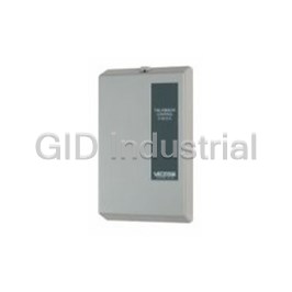
Description
Valcom V-9936A PLC Process Control Module - CO AUDIBLE RINGER 6 LINE UNIT
Part Number
V-9936A
Price
Request Quote
Manufacturer
VALCOM
Lead Time
Request Quote
Category
PRODUCTS - V
Specifications
Dimensions (HxWxD)
8.20" x 4.55" x 2.30"
Humidity
0 to 85% non-precipitating
Power Requirements
-21.5 to -26VDC "B" Battery, 200mA max
Temperature
0 to 50°C
Weight
1.5lbs, 0.68kg
Datasheet

Extracted Text
VSP-V-9936A Issue 5 V-9936A SIX LINE C. O. AUDIBLE RING UNIT INTRODUCTION The V-9936A is a Six Line C. O. Audible Ring Unit to be used with Electronic key and PABX telephone systems. These instructions contain the specifications and information necessary to install, operate and maintain the Six Line C. O. Audible Ring Unit. When installing the V-9936A, notify the local telephone company with the following information: · The telephone number of the lines to which the · Input for a night switch (On/Off switch) V-9936A will be connected · Built-in 66 type connection block · The FCC Registration number of the V-9936A, · May be connected to an existing paging system which is BAF9I7-12995-RG-N · Drives up to 150 Valcom One-way Amplified · The ringer equivalence number (REN): 0.7B Speaker Assemblies · Drives up to two 45 Ohm Talkback Speakers · May be used with One-way or Talkback Paging SPECIFICATIONS Systems Purpose · May be used with 70 Volt Paging Systems · Monitors up to six C. O. Lines or PABX station · Ring tone will override any page in progress numbers and gives a common audible tone signal · Volume control and a dry relay contact closure to indicate · Power reversal indicator incoming ring on any of the lines. · Powered by -24VDC "B" battery · V-9936A units may be multiplied to supervise additional lines. Capacity · Each V-9936A will provide signaling for six C.O. Applications lines or extension numbers · Central office lines · Up to four units may be multiplied for monitoring · PABX station numbers of 24 lines · Phone system night ring relay · May be connected to one zone of a paging system Features · The V-9936A will drive two 45 Ohm talkback · Monitors six lines speakers or 150 one-way amplified speaker · Units may be multiplied for additional lines assemblies · Provides interrupted electronic warble tone · The dry contact closure is rated at 1.0 Amp @ output for tone signaling 105VAC, or 2.0 Amps @ 24VDC. · Provides interrupted dry contact closure output to activate loud bells 1 947961 · V-9936A C. O. Ring Units, 1 per 6 lines Dimensions/Weight · VP-624B -24VDC Power Supply (VP-4024C if · 8.20" H x 4.55" W x 2.30" D using more than (3) V-9936A's). (20.83cm H x 11.56cm W x 5.84cm D) · 1.5 lbs. (.68 kg) If a page is in progress when an incoming call is detected, the ring signal from the V-9936A will Power Requirements momentarily override the page. -21.5 to -26VDC "B" Battery, 200mA maximum Environment C.O.1 TELEPHONE SYSTEM Temperature: 0 to +50 Degrees C C.O.2 (Page Control Unit may not be required) Humidity: 0 to 85% non-precipitating PAGE DESIGN C.O.6 OUT General The Valcom V-9936A is designed to monitor up to six V-9936A C. O. lines or PABX station numbers and will provide a common tone signal and contact closure whenever WARBLE TONE any of the lines are ringing. The V-9936A may be GENERATOR used with most telephone systems because it connects directly to the lines and not to the phones. The tone output may be connected to speakers used only for ringing or to one zone of a paging system. The dry contact closure may be used to activate loud FIGURE 1 - TYPICAL INSTALLATION ringing bells, strobes or other external equipment. Both outputs will provide interrupted signals INSTALLATION whenever any line is ringing. The following sections contain step-by-step instructions for wiring the V-9936A and associated A disable input is provided for connection of a night Valcom equipment. Each instruction is preceded by a switch. With no switch connected, the V-9936A will line; place a check on the appropriate line as the signal any time a line rings in. With a switch instruction is completed. The instructions also connected and providing a short across the disable include tests along the way to verify connections input, the unit will be inactive. have been made correctly. If these steps are followed exactly, installation should go smoothly and quickly. Stand-Alone Ringing If the results of a test do not correspond with what is The following components are required to provide shown, DO NOT PROCEED UNTIL THE PROBLEM common audible ringing over dedicated bells or HAS BEEN CORRECTED. speakers. Set individual volume controls at approximately 1/2 · V-9936A C. O. Ring Units, 1 per 6 lines volume for testing when installing the control unit · Signaling Devices consisting of: and any one-way amplified speaker assemblies. a. Two 45 Ohm talkback speakers or b. Up to 150 one-way amplified speakers or Mounting c. Loud bells, buzzers, strobes etc. as required Remove the metal mounting plate from the rear of the · Power Supply: The VP-624B will power a V-9936A V-9936A enclosure. Using two #6 x 3/4" wood using talkback speakers for signaling. If one-way screws, mount the plate in a vacant space on the speaker assemblies or other signaling devices are backboard with the telephone system common used, additional power may be required. equipment. Both mounting holes must be utilized to insure secure mounting of the unit. See Figure A. Ringing Over Paging Open the V-9936A enclosure to access connections Ringing may be connected to one zone of a Valcom and option switches. Slide the rear of the unit One-way or Talkback Paging System or to the INPUT (Contains the board) onto the mounting plate and of a high powered amplifier. The following lock in place with screw provided. Make connections components are required: and replace cover after all connections are accomplished. Lock cover in place using the #6 x 1/2" screw provided. 2 WIRE TIE LOOP TO REMOVE COVER WIRE TIE USED TO BUNDLE WIRES LOOSEN SCREW, ENTERING AND LEAVING TERMINAL AREA THEN ACTIVATE LATCH WIREWAY OPENING TO WALL PLATE AND .155 DIA. HOLES FOR MOUNTING TO JUNCTION BOX METAL WALL SINGLE OR DOUBLE GANG JUNCTION BOX MOUNTING HOLE PATTERN MATCHES BOTH EURO PLATE AND US JUNCTION BOXES SNAP LATCH 1.5 x 2 WIRE ACCESS OPENING CIRCUIT BOARD TO JUNCTION BOX HOUSING ASSEMBLY SNAP LATCH PLASTIC FOR COVER COVER BRACKET LOCKING SCREW FIGURE A 3 C.O.1 RING C.O.2 RING C.O.3 RING C.O.4 RING C.O.5 RING C.O.6 RING DISABLE OUT GROUND OUT PAGE OUT R CONTACT CLOSURE PAGE IN R GROUND IN -24VDC IN __ 3. Connect -24VDC Ground ("B" ground, "+" DO NOT locate the V-9936A or its wiring closer or "signal" ground) from power supply to than 18" to a power supply or any equipment pin 29 (GND). that generates electrical noise. __ 4. Connect -24VDC ground (+) from power supply to telephone system GND. __ 5. Power Test: Power Connections __ a. Plug in power supply. NOTE: The steps below must be completed for each __ b. If power reversal LED is lit - V-9936A being installed. (If not lit, go to step 6). __ (a) Unplug power supply. __ 1. Unplug power supply. __ (b) Reverse connections on V-9936A, pins __ 2. Connect -24VDC "B" battery (May be 29 (GND) and 30 (-24VDC). referred to as "-" or "signal battery") from __ (c) Go to step 6. power supply to pin 30 (-24VDC) on the __ 6. Unplug power supply. V-9936A. FIGURE 2 V-9936A Reverse Power LED Do Not Adjust Volume Control LoZ Speaker Select Switch HiZ 15 1 Connecting Block 30 16 LOCATION OF CONNECTING BLOCK AND CONTROLS 15 14 13 12 11 10 9 8 7 6 5 4 3 2 1 30 29 28 27 26 25 24 23 22 21 20 19 18 17 16 CONNECTING BLOCK PIN DESIGNATIONS 4 -24VDC OUT GROUND OUT PAGE IN T CONTACT CLOSURE PAGE OUT T -24VDC OUT DISABLE IN EXPANSION C.O.6 TIP C.O.5 TIP C.O.4 TIP C.O.3 TIP C.O.2 TIP C.O.1 TIP 9. If using Valcom speakers for signaling: Connecting Arrangements __ (a) Connect Tip of speaker to pin 11. · Proceed to Figure 3 for stand-alone ringing __ (b) Connect Ring of speaker to pin 26. connections. __ (c) If using one-way amplified speaker · Proceed to Figure 4 for ringing over paging assemblies: connections. __ (1) Connect the -24VDC speaker lead to · Proceed to Figure 5 for telephone system V-9936A pin 10. providing a dry contact closure for common __ (2) Connect the Ground speaker lead to pin audible signaling. 25. __ (d) Set the speaker select switch to Hi Z if WIRING INSTRUCTIONS: using 45 Ohm talkback speakers or set it to Place a check by each step as it is completed. Lo Z if using one-way amplified speakers. __ 1. Connect Tip of the first Central Office Line or 10. If using Bells or other devices for signaling: PABX station number to the V-9936A pin 1 __ (a) Connect one side of the output of an (C. O. 1 Tip). appropriate power source to pin 12 of the __ 2. Connect Ring of the first line or station to V-9936A. pin 16 (C. O. 1 Ring). __ (b) Connect the other side of the power source __ 3. Connect Tip of Line 2 to pin 2 and connect to one of the input terminals on your Ring of the line to pin 17. signaling device. __ 4. Connect Tip of Line 3 to pin 3 and connect __ (c) Connect from pin 27 of the V-9936A to the Ring of the line to pin 18. other input terminal of your signaling __ 5. Connect Tip of Line 4 to pin 4 and connect device. Ring of the line to pin 19. __ (d) Consult the information supplied with the __ 6. Connect Tip of Line 5 to pin 5 and connect signaling device for additional information. Ring of the line to pin 20. __ 11. If adding a night switch, connect it to pins 9 __ 7. Connect Tip of Line 6 to pin 6 and connect and 24. Ring of the line to pin 21. __ 12. Plug in power supply (See the Power __ 8. If using multiple V-9936A's: Connection section). __ (a) Connect a group of 6 lines or station __ 13. If using speakers for signaling, dial a line numbers to each V-9936A as in steps 1-7. connected to the V-9936A. When it starts __ (b) Connect wire from pin 8 (Expansion) of the ringing, adjust the V-9936A volume control main unit to pin 8 of each additional unit. to the desired level. 6 Central Office or TO PIN 8 OF Station ALL ADDITIONAL 1 Lines V-9936A's 15 14 13 12 11 10 9 8 7 6 5 4 3 2 1 V-9936A 30 29 28 27 26 25 24 23 22 21 20 19 18 17 16 24VDC POWER NIGHT SWITCH SUPPLY - + RING SUPPLY SPEAKERS LOUD BELL FIGURE 3 - STAND-ALONE RINGING CONNECTIONS 5 __10. If using Valcom paging speakers: WIRING INSTRUCTIONS: __(a) Note the location of the speaker wires on Place a check by each step as it is completed. the page control unit and remove them. __ 1. Connect Tip of the first Central Office line or __(b) Connect the speaker wires removed in (a) to PABX station number to the V-9936A pin 1 pins 11 (Tip) and 26 (Ring) of the V-9936A. (C.O. 1 Tip). __(c) Connect V-9936A pins 13 (Tip) and 28 __ 2. Connect Ring of the first line or station to (Ring) to the page control locations noted pin 16 (C. O. 1 Ring). in (a). __ 3. Connect Tip of line 2 to pin 2 and connect NOTE: If the page control unit provides background Ring of the line to pin 17. music input, the page out terminals may be connected __ 4. Connect Tip of line 3 to pin 3 and connect to the BGM input and the speakers connected directly Ring of the line to pin 18. to the Page Control Unit. __ 5. Connect Tip of line 4 to pin 4 and connect 11. If using a high power amplifier: Ring of the line to pin 19. __(a) Disconnect the paging signal wires from the __ 6. Connect Tip of line 5 to pin 5 and connect INPUT of the amplifier and connect them to Ring of the line to pin 20. the V-9936A pins 13 and 28. __ 7. Connect Tip of line 6 to pin 6 and connect __(b) Connect V-9936A pins 11 (Tip) and 26 Ring of the line to pin 21. (Ring) to the amplifier INPUT. 8. If using multiple V-9936A's: __ 12. Set the speaker select switch to Lo Z. __(a) Connect a group of 6 lines or station __ 13. If adding a night switch, connect it to pins 9 numbers to each V-9936A as in steps 1-7. and 24. __(b) Connect a wire from pin 8 (Expansion) of __ 14. Plug in power supply (See power the main unit to pin 8 of each additional connection section). unit. __ 15. Dial a line connected to the V-9936A. When __ 9. NOTE: Complete the wiring and testing of it starts ringing, adjust the V-9936A volume the paging system and properly adjust all control to the desired level. volume controls before continuing. Central 6 Office or Station 1 Lines 15 14 13 12 11 10 9 8 7 6 5 4 3 2 1 V-9936A 30 29 28 27 26 25 24 23 22 21 20 19 18 17 16 24VDC POWER SUPPLY NIGHT SWITCH - + PAGE CONTROL UNIT AUDIO OUT SPEAKERS FIGURE 4 - RINGING OVER PAGING CONNECTIONS 6 __ 3. If using a high power amplifier, connect pins WIRING INSTRUCTIONS 11 and 26 to a line level input on the __ 1. Connect telephone system dry contact amplifier. closure to pins 15 and 8. __ 4. If using a night switch, connect it to pins 9 __ 2. If using Valcom paging speakers: and 24. When the switch is closed, the __ (a) Connect audio output from page control V-9936A is disabled. unit to pins 13 and 28. __ 5. Set speaker select switch to the desired __(b) Connect Tip and Ring of each Valcom position Lo Z (8 Ohms) on a one-way speaker to pins 11 and 26. system, Hi Z (45 Ohms) on a talkback system. NOTE: If the page control unit provides a __ 6. Plug in power supply (See the Power background music input, the page out terminals may Connection section). be connected to the BGM input and the speaker __ 7. Test system and adjust volume as required. connected directly to the page control unit. TELEPHONE SYSTEM DRY CONTACT CLOSURE FOR NIGHT RING V-9936A 15 14 13 12 11 10 9 8 7 6 5 4 3 2 1 30 29 28 27 26 25 24 23 22 21 20 19 18 17 16 24VDC POWER NIGHT SWITCH SUPPLY - + PAGE CONTROL UNIT AUDIO OUT SPEAKERS FIGURE 5 - CONNECTIONS FOR A TELEPHONE SYSTEM WITH A COMMON AUDIBLE CONTACT CLOSURE 7 OPERATION TECHNICAL ASSISTANCE When a line rings in, the control circuitry and timer When trouble is reported, verify power is being are activated. While sensing the first incoming ring, supplied to the unit and there are no broken the unit will activate the output relay, disconnect the connections. Check voltages for proper polarity on page source and send a one second warble tone and the cross connect block. Table 1 identifies symptoms dry contact closure to the output. The relay will then of some possible problems with solutions. If a spare drop and paging will be reconnected. If additional unit is available, continue to troubleshoot by incoming rings are sensed during the next 4 seconds, substituting the spare unit for the suspected a second tone and closure will be sent. One second defective unit. tones and closures will then be sent every 4 seconds for as long as ringing is sensed on any line. If several Assistance in troubleshooting is available from the units are connected together using the expansion factory. When calling, you should have a VOM, leads, all units will send tones if a line rings in on any several clip leads, a telephone test set available and unit. Connecting the disable lead (pin 9) to ground be calling from the job site. Call (540) 563-2000 and (pin 24) will prevent the unit from being activated. ask for Technical Support, or (540) 767-1555 for Connecting a switch between these pins will allow Valcom 24-hour Faxback System or visit our website use of the V-9936A for night ringing. A simplified at http://www.valcom.com. schematic of the V-9936A is shown on the next page. The V-9936A is not field repairable. Valcom equipment contains no user serviceable parts inside. Valcom, Inc. maintains service facilities in Roanoke, VA. Should repairs be necessary, attach a tag to the unit clearly stating your company name, address, phone number, contact person and the nature of the problem. Send the unit to: Valcom, Inc. Repair and Return Dept. 5614 Hollins Road Roanoke, VA 24019-5056 TABLE 1: TROUBLESHOOTING CHART PROBLEMS POSSIBLE SOLUTIONS 1. No ring 1A. Verify -24VDC and ground on pins 30 and 29. Power reversal LED should not be on. 1B. Verify Disable In (Pin 9) is not grounded or connected to Disable Out (Pin 24). 2. Certain lines do not ring 2A. Verify trunk Tip and Ring connections. 3. Expansion unit does not 3A. Verify proper connection between Expansion Input leads (Pin 8) of ring units. 4. Low output to 45 Ohm 4A. Set Option Switch to Hi Z. speaker 4B. Turn V-9936A volume control up. 5. Overdrives amplified 5A. Set Option Switch to Lo Z. speaker 5B. Turn V-9936A volume control down. 6. Paging volume incorrect 6A. Adjust paging system volume according to instructions supplied with paging system. NOTE: The paging system volume MUST be properly set before adjusting the volume control on the V-9936A. 8 EXPANSION VOLUME CONTROL C.O.1 RING DETECT PAGE IN CONTROL TONE AND AMP GEN. TIMING PAGE OUT C.O.2 RING CIRCUIT DETECT OPTION SWITCH C.O.6 RING DETECT CONTACT CLOSURE SIMPLIFIED SCHEMATIC OF V-9936A VALCOM LIMITED WARRANTY Valcom, Inc. warrants its products to be free from defects in materials and workmanship under conditions of normal use and service for a period of one year from the date of shipment. The obligation under this warranty shall be limited to the replacement, re pair or refund of any such defective device within the warranty period, provided that: 1. inspection by Valcom, Inc. indicates the validity of the claim; 2. the defect is not the result of damage, misuse or negligence after the original shipment; 3. the product has not been altered in any way or repaired by others and that factory sealed units are unopened (A service charge plus parts and labor will be applied to units defaced or physically damaged); 4. freight charges for the return of products to Valcom are prepaid; 5. all units ‘out of warranty’ are subject to a service charge. The service charge will cover minor repairs (Major repairs will be subject to additional charges for parts and labor). This warranty is in lieu of and excludes all other warranties, expressed or implied and in no event shall Valcom, Inc. be liable for any anticipated profits, consequential damages, loss of time or other losses incurred by the buyer in connection with the purchase, operation or use of the product. This warranty specifically excludes damage incurred in shipment. In the event a product is received in damaged condition, the carrier should be notified immediately. Claims for such damage should be filed with the carrier involved in accordance with the F.O.B. point. Headquarters: In Canada Valcom, Inc. CMX Corporation 5614 Hollins Road 35 Van Kirk Drive #11 and 12 Roanoke, VA 24019-5056 Brampton, Ontario L7A 1A5 Phone: (540) 563-2000 Phone: (905) 456-1072 FAX: (540) 362-9800 FAX: (905) 456-2269 9
Frequently asked questions
What makes Elite.Parts unique?

What kind of warranty will the V-9936A have?
Which carriers does Elite.Parts work with?
Will Elite.Parts sell to me even though I live outside the USA?
I have a preferred payment method. Will Elite.Parts accept it?
Why buy from GID?

Quality
We are industry veterans who take pride in our work

Protection
Avoid the dangers of risky trading in the gray market

Access
Our network of suppliers is ready and at your disposal

Savings
Maintain legacy systems to prevent costly downtime

Speed
Time is of the essence, and we are respectful of yours
Related Products


VALCOM V-5328100A Universal Bi-directional Speaker | Amplicenter, PagePac 100 Watt

Request a Quote

The quote request has been received
Close

Facing challenges or have inquiries? Feel free to contact us!
Call Us +1-469-283-2440
What they say about us
FANTASTIC RESOURCE
One of our top priorities is maintaining our business with precision, and we are constantly looking for affiliates that can help us achieve our goal. With the aid of GID Industrial, our obsolete product management has never been more efficient. They have been a great resource to our company, and have quickly become a go-to supplier on our list!
Bucher Emhart Glass
EXCELLENT SERVICE
With our strict fundamentals and high expectations, we were surprised when we came across GID Industrial and their competitive pricing. When we approached them with our issue, they were incredibly confident in being able to provide us with a seamless solution at the best price for us. GID Industrial quickly understood our needs and provided us with excellent service, as well as fully tested product to ensure what we received would be the right fit for our company.
Fuji
HARD TO FIND A BETTER PROVIDER
Our company provides services to aid in the manufacture of technological products, such as semiconductors and flat panel displays, and often searching for distributors of obsolete product we require can waste time and money. Finding GID Industrial proved to be a great asset to our company, with cost effective solutions and superior knowledge on all of their materials, it’d be hard to find a better provider of obsolete or hard to find products.
Applied Materials
CONSISTENTLY DELIVERS QUALITY SOLUTIONS
Over the years, the equipment used in our company becomes discontinued, but they’re still of great use to us and our customers. Once these products are no longer available through the manufacturer, finding a reliable, quick supplier is a necessity, and luckily for us, GID Industrial has provided the most trustworthy, quality solutions to our obsolete component needs.
Nidec Vamco
TERRIFIC RESOURCE
This company has been a terrific help to us (I work for Trican Well Service) in sourcing the Micron Ram Memory we needed for our Siemens computers. Great service! And great pricing! I know when the product is shipping and when it will arrive, all the way through the ordering process.
Trican Well Service
GO TO SOURCE
When I can't find an obsolete part, I first call GID and they'll come up with my parts every time. Great customer service and follow up as well. Scott emails me from time to time to touch base and see if we're having trouble finding something.....which is often with our 25 yr old equipment.
ConAgra Foods