

 Manufacturers
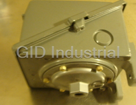
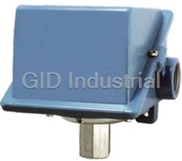
UNITED ELECTRIC J403
Description
United Electric J403 Pressure, Vacuum, Differential Pressure and Temperature Switches
Part Number
J403
Price
Request Quote
Manufacturer
UNITED ELECTRIC
Lead Time
Request Quote
Category
PRODUCTS - J
Specifications
Ambient temperature
-40 to 160°F (-40 to 71°C); set point typically shifts less than 1% of range for limitS a 50°F (28°C) ambient temperature change
Electircal Connection
One 3/4” NPT and two 7/8” diameter knockouts
Electrical rating
15 A 125/250/480 VAC resistive. Electrical switches have limited D
encloSure
Die cast aluminum, epoxy powder coated, gasketed, captive cover screws
EncloSure Classification
Designed to meet enclosure type 4X requirements classification
Fill
Temperature Models: Model 1BS: solvent filled; models 2-8: non-toxic oil filled
Shock
Set point repeats after 15 G, 10 millisecond duration
Storage temperature
-65 to 160°F (-54 to 71°C)
Temperature Deadband
Type F typically 1% and type E, B & C typically 2% of range under laboratory conditions (70°F ambient circulating bath at rate of 1/2°F per minute change)
Vibration
Set point repeats after 2.5 G, 5-500 Hz
Weight
Approx. 3 to 7.5 lbs.; varies with model
Features
- 1, 2 & 3 switch outputs
- epoxy-coated enclosure designed
- fmapproved
- materials
- screw adjustment
- setting via reference dial or hex
- to meet enclosure type 4X
- Wide variety of pressure sensors and
Datasheet

Extracted Text
400 Series 400 Series Pressure, Vacuum, Differential Pressure anD temPerature sWitcHes featureS • 1, 2 & 3 switch outputs • epoxy-coated enclosure designed to meet enclosure type 4X • Wide variety of pressure sensors and materials • setting via reference dial or hex screw adjustment • fm approved • adjustable ranges: "WC ranges: 300 "wc vacuum to 250 “wc pressure (-746,7 to 622,3 mbar) Pressure: 30 “Hg Vac to 6000 psi (-1,0 to 413,7 bar) Differential Pressure: 1"wcd to 200 psid (2.5 mbar to 13,8 bar) Temperature: -180 to 650 °F (-117.8 to 343.3 °C) 4 0 0 - B - 0 8 LEADERS IN SAFETY, ALARM & SHUTDOWN 400 Series overview features The 400 Series is a versatile family of vacuum, pressure, differential • UL listed and cUL certified. pressure and temperature switches for applications that require single FM approved. or multiple switching capabilities. Dual and triple switch versions • CE compliant to low voltage provide multi-output for alarm and shutdown, pre-alarm and alarm, directive and pressure equipment high/low limit or level staging functions. directive. A wide variety of microswitch and process connection options, along • Optional ATEX or GOST intrinsic with a weather-tight enclosure, make the 400 Series an ideal choice safety compliance. for most ordinary location applications. Its worldwide use is assured • One, two or three switch outputs with approvals and certifications to agency standards. may be separated up to 100% of Widely used throughout the process industries, the 400 Series range. provides threshold protection and control for many critical functions. • Wide variety of available options Typical installations are found in industrial gas production, energy and pressure sensor modules. generation including pumps, turbines and compressors, pulp and paper, and water and wastewater treatment. • Most models available for immediate delivery. Differential Pressure Reference scale, for types B, E & H Model with M210 with option M321 Option - Dial Indication Enlarged View Temperature Model with Remote Bulb Dual Switch, Low Water & Capillary and M321 option - Column Differential Gasketed Lexan® Window Pressure Model Lexan® is a registered trademark of Sabic Innovative Plastics 2 w w w . u e o n l i n e . c o m 4 0 0 - B - 0 8 400 Series 400 Series specifications Storage temperature -65 to 160°F (-54 to 71°C) ambient temperature -40 to 160°F (-40 to 71°C); set point typically shifts less than 1% of range for limitS a 50°F (28°C) ambient temperature change Set point Temperature models: ± 2% of full scale range repeatability Pressure: models 126-376, 520-535, 540-547, 570-572, S126B-S164B: ± 2% of full scale range; models 440-457, 550-559: ± 1% of full scale range; models 610-614: ± 3% of full scale range Shock Set point repeats after 15 G, 10 millisecond duration Vibration Set point repeats after 2.5 G, 5-500 Hz encloSure Die cast aluminum, epoxy powder coated, gasketed, captive cover screws encloSure Designed to meet enclosure type 4X requirements claSSification Switch output One, two or three SPDT switches, may be separated up to 100% of range except models 521-524, 531-534: 50%; models 520, 525, 530, 535, 570-572: 30%; switches may be wired “normally open” or “normally closed” electrical rating 15 A 125/250/480 VAC resistive. Electrical switches have limited DC capabilities. Consult factory for additional information. weight Approx. 3 to 7.5 lbs.; varies with model electrical One 3/4” NPT and two 7/8” diameter knockouts connection preSSure All models 1/4” NPT (female) except models S126B-S164B, 520-535: 1/2” NPT connection (female); models 540-547: 1/8" NPT (female) temperature ‘E’ types use the same assemblies as ‘F’ types, however, range spans are limited aSSembly due to use of reference dials Bulb and capillary: 6 feet 304 stainless steel Immersion stem: models 120 &121: nickel-plated brass; optional 316L stainless steel available fill Temperature Models: Model 1BS: solvent filled; models 2-8: non-toxic oil filled temperature Type F typically 1% and type E, B & C typically 2% of range under laboratory deadband conditions (70°F ambient circulating bath at rate of 1/2°F per minute change) differential Differential pressure indication available J400K, J402K models 147-S157B; preSSure indicator accuracy approximately 1-1⁄2% mid 50% of range, 3% at ends; window is (option m210) plexiglass and gasketed; indicator may be field adjusted for approximately ±1% accuracy at any set point within range 4 0 0 - B - 0 8 w w w . u e o n l i n e . c o m 3 400 Series approvals united StateS and canada type 400 & 402 ul listed, cul certified Pressure: UL 508; CSA C22.2 No. 14, file # E42272 Temperature: UL 873; CSA C22.2 No. 24, file # E10667 type 403 ul recognized, cul recognized Pressure: UL 508; CSA C22.2 No. 14, file # E42272 Temperature: UL 873; CSA C22.2 No. 24, file # E10667 all types fm approved Pressure: Class 3510 Temperature: Class 3545 europe ateX directive (94/9/ec) II 1 G Ex ia IIC T6 Ga (optional – code m405) Tamb = -50°C to +60°C UL International DEMKO A/S (N.B.# 0539) Certificate # DEMKO 11 ATEX 1105621X Rev. 0 EN 60079-0, 60079-11 & 60079-26 low Voltage directive (lVd) (2006/95/ec) Compliant to LVD Products rated lower than 50 VAC and 75 VDC are outside of the scope of the LVD pressure equipment directive (ped) (97/23/ec) Compliant to PED Products rated below 7.5 PSI are outside the scope of PED ruSSia Gosgortechnadzor Permit (optional – code m406) 0ExiaIICT6 Tamb = -50˚C to +60˚C NANIO CCVE Certification Center Certificate # ROSS US.GB05.Bo2933 GOST R 51330.0, 51330.1, 51330.10 & 51330.14 4 w w w . u e o n l i n e . c o m 4 0 0 - B - 0 8 400 Series 400 Series pressure model chart Type J400, single switch output with internal hex screw adjustment Type J402, dual switch output with internal hex screw adjustment Type J403, triple switch output with internal hex screw adjustment model adjustable set Point range Deadband Over range Pressure* Proof Pressure** low end of range on fall; Deadband doubles for High end of range on rise 2 and 3 switch types “wc mbar “wc mbar psi bar psi bar Buna-N diaphragm and O-Ring with epoxy coated aluminum 1/2” NPT (female) pressure connection, large 0.72” orifice for clean-out purposes. Other wetted materials available, see pg. 12; Option M449 recommended 520† 300 Vac to 0 -746,7 to 0 0.2 to 12 0,5 to 29,9 200 13,8 400 27,6 521† 10 Vac to 10 -24,9 to 24,9 0.1 to 1 0,2 to 2,5 200 13,8 400 27,6 522† 50 Vac to 50 -124,5 to 124,5 0.1 to 5 0,2 to 12,4 200 13,8 400 27,6 523† 0.5 to 5.0 1,2 to 12,4 0.1 to 0.3 0,2 to 0,7 200 13,8 400 27,6 524† 2.5 to 50 6,2 to 124,5 0.1 to 2 0,2 to 5,0 200 13,8 400 27,6 525† 10 to 250 24,9 to 622,3 0.1 to 10 0,2 to 24,9 200 13,8 400 27,6 Welded 316L stainless steel diaphragm and 1/2” NPT (female) pressure connection, large 0.72” orifice for clean-out purposes; Option M449 recommended 530† 300 Vac to 0 -746,7 to 0 0.2 to 15 0,5 to 37,3 50 3,4 100 6,9 531† 10 Vac to 10 -24,9 to 24,9 0.1 to 1 0,2 to 2,5 50 3,4 100 6,9 532† 50 Vac to 50 -124,5 to 124,5 0.1 to 6 0,2 to 14,9 50 3,4 100 6,9 533† 0.5 to 5.0 1,2 to 12,4 0.1 to 0.3 0,2 to 0,7 50 3,4 100 6,9 534† 2.5 to 50 6,2 to 124,5 0.1 to 2.5 0,2 to 6,2 50 3,4 100 6,9 535† 10 to 250 24,9 to 622,3 0.1 to 10 0,2 to 24,9 50 3,4 100 6,9 psi bar psi bar psi bar psi bar (unless noted) (unless noted) (unless noted) (unless noted) (unless noted) (unless noted) 316L stainless steel diaphragm and Viton® O-Ring with 316L stainless steel 1/4" NPT (female) pressure connection 1 570 0 to 20 0 to 1,4 0.2 to 4 13,8 to 275,8 mbar 20 1,4 225 15,5 1 571 0 to 50 0 to 3,4 0.7 to 6 48,3 to 413,7 mbar 50 3,4 225 15,5 1 572 0 to 100 0 to 6,9 1 to 7 0,1 to 0,5 100 6,9 225 15,5 Welded 316L stainless steel bellows and 1/2” NPT (female) pressure connection S126B 30 ”Hg Vac to 0 -1 to 0 0.2 to 0.9 ”Hg 6,8 to 30,5 mbar 3 0,2 5 0,3 S134B 30 ”Hg Vac to 20 psi -1 to 1,4 0.2 to 1.2 ”Hg 6,8 to 40,6 mbar 20 1,4 25 1,7 S137B 0 to 80 ”wc 0 to 199,1 mbar 2 to 6 ”wc 5 to 14,9 mbar 80 “wc 199,1 mbar 5 0,3 S144B 0 to 20 0 to 1,4 0.1 to 0.5 6,9 to 34,5 mbar 20 1,4 25 1,7 S146B 0 to 30 0 to 2,1 0.1 to 0.6 6,9 to 41,4 mbar 30 2,1 40 2,8 S156B 0 to 100 0 to 6,9 0.2 to 0.8 13,8 to 55,2 mbar 100 6,9 125 8,6 S164B 0 to 200 0 to 13,8 0.3 to 2 20,7 to 137,9 mbar 200 13,8 200 13,8 Welded 316L stainless steel bellows and 1/4” NPT (female) pressure connection 358 0 to 200 0 to 13,8 1.5 to 8 0,1 to 0,6 200 13,8 250 17,2 361 0 to 300 0 to 20,7 2 to 9 0,1 to 0,6 300 20,7 350 24,1 376 0 to 500 0 to 34,5 3 to 12 0,2 to 0,8 500 34,5 575 39,6 *Over Range Pressure: The maximum pressure that may be applied continuously without causing damage and maintaining set point repeatability **Proof pressure: The maximum pressure to which a pressure sensor may be subjected, which causes no permanent damage. The unit may require calibration (e.g. start-up, testing). † model not available on types J400 and J403; actual deadband shown, do not double – switch separation a maximum of 30 - 50% of range. 1 Switch separation of 30% maximum for dual and triple switch units. 4 0 0 - B - 0 8 w w w . u e o n l i n e . c o m 5 400 Series pressure model chart Type J400, single switch output with internal hex screw adjustment Type J402, dual switch output with internal hex screw adjustment Type J403, triple switch output with internal hex screw adjustment model adjustable set Point range Deadband Over range Pressure* Proof Pressure** Low end of range on fall; Deadband doubles for High end of range on rise 2 and 3 switch types psi bar psi bar psi bar psi bar (unless noted) (unless noted) (unless noted) 303 stainless steel piston with Buna-N O-Ring and 303 stainless steel 1/4” NPT (female) pressure connection (not recommended for gas service since drying of the O-Ring seal can allow bleeding of medium into the atmosphere) 610 100 to 1,000 6,9 to 68,9 30 to 150 2,1 to 10,3 6,000 413,7 10,000 689,5 612 200 to 3,000 13,8 to 206,8 40 to 250 2,8 to 17,2 6,000 413,7 10,000 689,5 614 500 to 6,000 34,5 to 413,7 50 to 400 3,4 to 27,6 6,000 413,7 10,000 689,5 Brass bellows with nickel-plated brass 1/4” NPT (female) pressure connection; Models 126 and 134 have zinc-plated steel spring exposed to media 126 30 ”Hg Vac to 0 -1 to 0 0.2” to 0.9 ”Hg 6,8 to 30,5 mbar 3 0,2 5 0,3 134 30 ”Hg Vac to 20 psi -1 to 1,4 0.2” to 1.2 ”Hg 6,8 to 40,6 mbar 20 1,4 25 1,7 137 0 to 80 ”wc 0 to 199,1 mbar 2 to 6 ”wc 5 to 14,9 mbar 3 0.2 5 0,3 144 0 to 20 0 to 1,4 0.1 to 0.5 6,9 to 34,5 mbar 20 1,4 25 1,7 146 0 to 30 0 to 2,1 0.1 to 0.6 6,9 to 41,4 mbar 30 2 40 2,8 156 0 to 100 0 to 6,9 0.2 to 0.8 13,8 to 55,2 mbar 100 6,9 125 8,6 164 0 to 200 0 to 13,8 0.3 to 2 20,7 to 137,9 mbar 200 13,8 200 13,8 Phosphor bronze bellows with nickel-plated brass 1/4” NPT (female) pressure connection 270 0 to 200 0 to 13,8 1.5 to 8 0,1 to 0,6 200 13,8 250 17,2 274 0 to 300 0 to 20,7 2 to 10 0,1 to 0,7 300 20,7 350 24,1 Buna-N diaphragm and O-Ring with aluminum 1/4” NPT (female) pressure connection and cap; Models 448, 450 & 452 have stainless steel pressure connection and cap 440†† 0 to 2 ”wc 0 to 5 mbar 0.07 to 0.25 ”wc 0,2 to 0,6 mbar 3 0,2 225 15,5 441††† 0 to 10 ”wc 0 to 24,9 mbar 0.15 to 0.4 ”wc 0,4 to 1,0 mbar 3 0,2 225 15,5 442 0 to 20 ”wc 0 to 49,8 mbar 0.2 to 0.6 ”wc 0,5 to 1,5 mbar 3 0,2 225 15,5 443 0 to 80 ”wc 0 to 199,1 mbar 0.5 to 2 ”wc 1,2 to 5,0 mbar 3 0,2 225 15,5 448 80 “wc Vac to 0 -199,1 to 0 mbar 1 to 3 ”wc 2,5 to 7,5 mbar 3 0,2 225 15,5 449††† 0 to 20 ”wc 0 to 49,8 mbar 1 to 2 ”wc 2,5 to 5,0 mbar 3 0,2 225 15,5 450 30 ”Hg Vac to 0 -1 to 0 0.1 to 0.4 ”Hg 3,4 to 13,5 mbar 3 0,2 225 15,5 451 0 to 80 ”wc 0 to 199,1 mbar 1 to 3 ”wc 2,5 to 7,5 mbar 3 0,2 225 15,5 452 30 ”Hg Vac to 20 psi -1 to 1,4 0.2 to 1 ”Hg 6,8 to 33,9 mbar 20 1,4 225 15,5 453 0 to 20 0 to 1,4 0.05 to 0.2 3,4 to 13,8 mbar 20 1,4 225 15,5 454 0 to 30 0 to 2,1 0.05 to 0.3 3,4 to 20,7 mbar 30 2,1 225 15,5 Teflon® diaphragm and Viton® O-Ring with 316L stainless steel 1/4” NPT (female) pressure connection and cap 550 30 ”Hg Vac to 0 -1 to 0 0.1 to 0.6 ”Hg 3,4 to 20,3 mbar 3 0,2 225 15,5 551 0 to 80 ”wc 0 to 199,1 mbar 1.5 to 3.5 ”wc 3,7 to 8,7 mbar 3 0,2 225 15,5 552 30 ”Hg Vac to 20 psi -1 to 1,4 0.2 to 1 ”Hg 6,8 to 33,9 mbar 20 1,4 225 15,5 553 0 to 20 0 to 1,4 0.05 to 0.3 3,4 to 20,7 mbar 20 1,4 225 15,5 554 0 to 30 0 to 2,1 0.1 to 0.4 6,9 to 27,6 mbar 30 2,1 225 15,5 555 0 to 100 0 to 6,9 0.25 to 0.75 17,2 to 51,7 mbar 100 6,9 225 15,5 6 w w w . u e o n l i n e . c o m 4 0 0 - B - 0 8 Teflon® and Viton® are registered trademarks of E.I. DuPont de Nemours and Company †† model not available on types J402 and J403 ††† model not available on type J403 400 Series 400 Series pressure model chart Type H400, single switch output with internal adjustment via reference dial Type H402, dual switch output with internal adjustment via reference dial Type H403, triple switch output with internal adjustment via reference dial model adjustable set Point range Deadband Proof Pressure** scale Division High end of range on rise Deadband doubles for Low end of range on fall; 2 and 3 switch types psi bar psi bar psi bar psi (unless noted) (unless noted) (unless noted) (unless noted) (unless noted) Welded 316L stainless steel bellows and 1/2” NPT (female) pressure connection S126B 30 ”Hg Vac to 0 -1 to 0 0.2 to 0.9 ”Hg 6,8 to 30,5 mbar 5 0,3 2 ”Hg S134B 30 ”Hg Vac to 20 psi -1 to 1,4 0.2 to 1.2 ”Hg 6,8 to 40,6 mbar 25 1,7 2 ”Hg & 2 psi S137B† 0 to 80 ”wc 0 to 199,1 mbar 2 to 6 ”wc 5 to 14,9 mbar 5 0,3 5 ”wc S144B 0 to 20 0 to 1,4 0.1 to 0.5 6,9 to 34,5 mbar 25 1,7 1 S146B 0 to 30 0 to 2,1 0.1 to 0.6 6,9 to 41,4 mbar 40 2,8 1 S156B 0 to 100 0 to 6,9 0.2 to 0.8 13,8 to 55,2 mbar 125 8,6 5 S164B 0 to 200 0 to 13,8 0.3 to 2 20,7 to 137,9 mbar 200 13,8 10 Welded 316L stainless steel bellows and 1/4” NPT (female) pressure connection 358 0 to 200 0 to 13,8 1.5 to 8 0,1 to 0,6 250 17,2 10 361 0 to 300 0 to 20,7 2 to 9 0,1 to 0,6 350 24,1 10 376 0 to 500 0 to 34,5 3 to 12 0,2 to 0,8 575 39,6 20 Brass bellows with nickel-plated brass 1/4” NPT (female) pressure connection; Models 126 and 134 have zinc-plated steel spring exposed to media 126 30 ”Hg Vac to 0 -1 to 0 0.2 to 0.9 ”Hg 6,8 to 30,5 mbar 5 0,3 2 ”Hg 134 30 ”Hg Vac to 20 psi -1 to 1,4 0.2 to 1.2 ”Hg 6,8 to 40,6 mbar 25 1,7 2 ”Hg & 2 psi 137† 0 to 80 ”wc 0 to 199,1 mbar 2 to 6 ”wc 5 to 14,9 mbar 5 0,3 5 ”wc 144 0 to 20 0 to 1,4 0.1 to 0.5 6,9 to 34,5 mbar 25 1,7 1 146 0 to 30 0 to 2,1 0.1 to 0.6 6,9 to 41,4 mbar 40 2,8 1 156 0 to 100 0 to 6,9 0.2 to 0.8 13,8 to 55,2 mbar 125 8,6 5 164 0 to 200 0 to 13,8 0.3 to 2 20,7 to 137,9 mbar 200 13,8 10 Phosphor bronze bellows with nickel plated brass 1/4” NPT (female) pressure connection 270†† 0 to 200 0 to 13,8 1.5 to 8 0,1 to 0,6 250 17,2 10 274†† 0 to 300 0 to 20,7 2 to 10 0,1 to 0,7 350 24,1 10 Buna-N diaphragm and O-Ring with aluminum 1/4” NPT (female) pressure connection and cap; Models 448, 450 & 452 have stainless steel pressure connection and cap 441† 0 to 10 “wc 0 to 24,9 mbar 0.15 to 0.4 “wc 0,4 to 1,0 mbar 225 15,5 0.5 “wc 442† 0 to 20 “wc 0 to 49,8 mbar 0.2 to 0.6 “wc 0,5 to 1,5 mbar 225 15,5 1 “wc 443† 0 to 80 “wc 0 to 199,1 mbar 0.5 to 2 “wc 1,2 to 5,0 mbar 225 15,5 5 “wc 448† 80 “wc Vac to 0 -199,1 to 0 mbar 1 to 3 “wc 2,5 to 7,5 mbar 225 15,5 5 “wc 450†† 30 “Hg Vac to 0 -1 to 0 0.1 to .04 “Hg 3,4 to 13,5 mbar 225 15,5 2 “Hg 452†† 30 “Hg Vac to 20 psi -1 to 1,4 0.1 to 1 “Hg 3,4 to 33,9 mbar 225 15,5 2 “Hg & 2 psi 453†† 0 to 20 0 to 1,4 0.05 to 0.2 3,4 to 13,8 mbar 225 15,5 1 454†† 0 to 30 0 to 2,1 0.05 to 0.3 3,4 to 20,7 mbar 225 15,5 1 **Proof pressure: The maximum pressure to which a pressure sensor may be subjected, which causes no permanent damage. The unit may require calibration (e.g. start-up, testing). † model not available on types h402 and h403 †† model not available on type h403 4 0 0 - B - 0 8 w w w . u e o n l i n e . c o m 7 400 Series pressure model chart Type H400, single switch output with internal adjustment via reference dial Type H402, dual switch output with internal adjustment via reference dial Type H403, triple switch output with internal adjustment via reference dial model adjustable set Point range Deadband Proof Pressure** scale Division Low end of range on fall; Deadband doubles for High end of range on rise 2 and 3 switch types psi bar psi bar psi bar psi (unless noted) (unless noted) (unless noted) (unless noted) (unless noted) Teflon® diaphragm and Viton® O-Ring with 316L stainless steel 1/4” NPT (female) pressure connection and cap 550†† 30 “Hg Vac to 0 -1 to 0 0.1 to 0.6 “Hg 3,4 to 20,3 mbar 225 15,5 2 “Hg 552†† 30 “Hg Vac to 20 psi -1 to 1,4 0.2 to 1 “Hg 6,8 to 33,9 mbar 225 15,5 2 “Hg & 2 psi 553†† 0 to 20 0 to 1,4 0.05 to 0.3 3,4 to 20,7 mbar 225 15,5 1 554†† 0 to 30 0 to 2,1 0.1 to 0.4 6,9 to 27,6 mbar 225 15,5 1 555†† 0 to 100 0 to 6,9 0.25 to 0.75 17,2 to 51,7 mbar 225 15,5 5 **proof pressure: The maximum pressure to which a pressure sensor may be subjected, which causes no permanent damage. The unit may require calibration (e.g. start-up, testing). † model not available on types h402 and h403 †† model not available on type h403 differential pressure model chart Type J400K, single switch output with internal hex screw adjustment Type J402K, dual switch output with internal hex screw adjustment model adjustable set Point range Deadband Working Pressure*** Proof Pressure** Low end of range on fall: Deadband doubles for High end of range on rise 2 switch types psid bar psi mbar psi bar psi bar (unless noted) (unless noted) (unless noted) Welded 316L stainless steel bellows and 1/2” NPT (female) pressure connections S147B 3 to 30 0,2 to 2,1 0.5 to 2 34,5 to 137,9 30 ”Hg Vac to 100 -1 to 6,9 300 20,7 S157B 10 to 100 0,7 to 6,9 0.5 to 3 34,5 to 206,8 30 ”Hg Vac to 180 -1 to 12,4 300 20,7 Brass bellows with nickel-plated brass 1/4” NPT (female) pressure connections 147 3 to 30 0,2 to 2,1 0.5 to 2 34,5 to 137,9 30 ”Hg Vac to 100 -1 to 6,9 180 12,4 157 10 to 100 0,7 to 6,9 0.5 to 3 34,5 to 206,8 30 ”Hg Vac to 150 -1 to 10,3 180 12,4 Buna-N diaphragm and O-Ring with aluminum 1/4” NPT (female) pressure connections 455 5 to 80 ”wcd 12,4 to 199,1 mbar 1 to 4 ”wc 2,5 to 10 30 ”Hg Vac to 225 -1 to 15,5 225 15,5 456 2 to 20 0,1 to 1,4 0.1 to 0.3 6,9 to 20,7 30 ”Hg Vac to 225 -1 to 15,5 225 15,5 457 3 to 30 0,2 to 2,1 0.1 to 0.4 6,9 to 27,6 30 ”Hg Vac to 225 -1 to 15,5 225 15,5 ***Working Pressure Range: The pressure range within which two opposing sensors can be safely operated and still maintain set point adjustability. 8 w w w . u e o n l i n e . c o m 4 0 0 - B - 0 8 400 Series 400 Series differential pressure model chart Type J400K, single switch output with internal hex screw adjustment Type J402K, dual switch output with internal hex screw adjustment model adjustable set Point range Deadband Working Pressure*** Proof Pressure** Low end of range on fall; Deadband doubles for High end of range on rise 2 and 3 switch types psid bar psi bar psi bar psi bar (unless noted) (unless noted) (unless noted) (unless noted) Buna-N diaphragms and o-ring with epoxy coated aluminum 1/8” NPT (female) pressure connections (J402K only); Option M449 recommended 540† 1 to 7 “wcd 2.5 to 17,4 mbar 0.1 to 0.5“wc 0,2 to 1,2 mbar 30 ”Hg Vac to 200 -1 to 13,8 400 27,6 541† 2 to 20 “wcd 5 to 49,8 mbar 0.5 to 2 “wc 1,2 to 5 mbar 30 ”Hg Vac to 200 -1 to 13,8 400 27,6 542† 5 to 50 “wcd 12,4 to 124,5 mbar 0.5 to 5 “wc 1,2 to 12,4 mbar 30 ”Hg Vac to 200 -1 to 13,8 400 27,6 543† 15 to 100 “wcd 37,3 to 248,9 mbar 0.5 to 7 “wc 1,2 to 17,4 mbar 30 ”Hg Vac to 200 -1 to 13,8 400 27,6 544† 2 to 20 0,1 to 1,4 1 to 2.5 0,1 to 0,2 30 ”Hg Vac to 1200 -1 to 82,7 2500 172,4 545† 5 to 50 0,3 to 3,4 1 to 3 0,1 to 0,2 30 ”Hg Vac to 1200 -1 to 82,7 2500 172,4 546† 10 to 100 0,7 to 6,9 1 to 5 0,1 to 0,3 30 ”Hg Vac to 1200 -1 to 82,7 2500 172,4 547† 20 to 200 1,4 to 13,8 1 to 7 0,1 to 0,5 30 ”Hg Vac to 1200 -1 to 82,7 2500 172,4 Teflon® and Buna-N diaphragms, Buna-N O-Ring with aluminum 1/4” NPT (female) pressure connections 559 10 to 100 0,7 to 6,9 0.2 to 1 13,8 to 68,9 mbar 30 ”Hg Vac to 225 -1 to 15,5 225 15,5 Type H400K, single switch output with internal adjustment via reference dial Type H402K, dual switch output with internal adjustment via reference dial Buna-N diaphragm and O-Ring with 1/4” NPT (female) aluminum pressure connections 455 5 to 80 ”wcd 12,4 to 199,1 mbar 1 to 4 ”wc 2,5 to 10 mbar 30 ”Hg Vac to 225 -1 to 15,5 225 15,5 456 2 to 20 0,1 to 1,4 0.1 to 0.3 6,9 to 20,7 mbar 30 ”Hg Vac to 225 -1 to 15,5 225 15,5 457 3 to 30 0,2 to 2,1 0.1 to 0.4 6,9 to 27,6 mbar 30 ”Hg Vac to 225 -1 to 15,5 225 15,5 Teflon and Buna-N diaphragms, Buna-N O-Ring with 1/4” NPT (female) aluminum pressure connections 559 10 to 100 0,7 to 6,9 0.2 to 1 13,8 to 68,9 mbar 30 “Hg Vac to 225 -1 to 15,5 225 15,5 ***Working Pressure Range: The pressure range within which two opposing sensors can be safely operated and still maintain set point adjustability. † model not available on type J400k; actual deadband shown, do not double 4 0 0 - B - 0 8 w w w . u e o n l i n e . c o m 9 400 Series temperature model chart Type B400, single switch output, immersion stem, internal adjustment via reference dial Type B402, dual switch output, immersion stem, internal adjustment via reference dial Type B403, triple switch output, immersion stem, internal adjustment via reference dial Type C400, single switch output, immersion stem, internal hex screw adjustment Type C402, dual switch output, immersion stem, internal hex screw adjustment Type C403, triple switch output, immersion stem, internal hex screw adjustment Type E400, single switch output, bulb & capillary***, internal adjustment via reference dial Type E402, dual switch output, bulb & capillary***, internal adjustment via reference dial Type E403, triple switch output, bulb & capillary***, internal adjustment via reference dial Type F400, single switch output, bulb & capillary***, internal hex screw adjustment Type F402, dual switch output, bulb & capillary***, internal hex screw adjustment Type F403, triple switch output, bulb & capillary***, internal hex screw adjustment model adjustable set Point range max. temp. scale Division†† stem or Bulb size*/finish** °F °C °F °C °F °C OD x Length Type B400, B402, B403, single, dual, or triple switch output, immersion stem, internal adjustment via reference dial. Type C400, C402, C403, single, dual, or triple switch output, immersion stem, internal hex screw adjustment 120 0 to 225 -17.8 to 107.2 275 135 5 5 9/16" x 1-7 ⁄ 8" nickel-plated brass 121 200 to 425 93.3 to 218.3 475 246.1 5 5 9/16" x 1-7 ⁄ 8" nickel-plated brass Type E400, E402, E403, single, dual, or triple switch output, bulb & capillary***, internal adjustment via reference dial 2BSA -120 to 100 -84.4 to 37.8 150 65.6 10 5 3/8 x 2-5/8” 2BSB 30 to 250 -1.1 to 121.1 300 148.9 10 5 3/8 x 2-5/8” 3BS 100 to 400 37.8 to 204.4 450 232.2 10 10 3/8 x 2-1⁄ 8” 4BS 25 to 100 -3.9 to 37.8 150 65.6 5 2 3/8 x 6-3⁄ 4” 5BS -20 to 80 -28.9 to 26.7 130 54.4 5 2 3/8 x 5” 8BS 350 to 640 176.7 to 337.8 690 365.6 10 10 3/8 x 3-1⁄ 4” Type F400, F402, F403, single, dual, or triple switch output, bulb & capillary***, internal hex screw adjustment 1BS† -180 to 120 -117.8 to 48.9 170 76.7 N/A 3/8 x 3-3⁄4” 2BS -125 to 350 -87.2 to 176.7 400 204.4 N/A 3/8 x 2-5/8” 3BS -125 to 500 -87.2 to 260 550 287.8 N/A 3/8 x 2-1⁄8” 4BS -40 to 120 -40 to 48.9 170 76.7 N/A 3/8 x 6-3⁄4” 5BS -40 to 180 -40 to 82.2 230 110 N/A 3/8 x 5” 6BS 0 to 250 -17.8 to 121.1 300 148.9 N/A 3/8 x 4-1⁄2” 7BS 0 to 400 -17.8 to 204.4 450 232.2 N/A 3/8 x 3” 8BS 50 to 650 10 to 343.3 700 371.1 N/A 3/8 x 3-1⁄4” † model not available on type f403 †† only applies to types b400, b402, b403, e400, e402 and e403 * optional immersion stem lengths and capillary lengths are available ** optional stainless steel immersion stem and capillary covering available *** Standard capillary lengths are 6ft 10 w w w . u e o n l i n e . c o m 4 0 0 - B - 0 8 400 Series 400 Series how to order BuilDing a Part numBer Select a type Select a model Select an option Refer to the “Type” section below. Refer to the “Model Charts”. Refer to the “Options” section. Determine type number based on switch Determine model based on adjustable Determine option number based on switch output, enclosure, adjustment and range, deadband and proof pressure. output, optional materials or other product reference. enhancements. Fill in the model portion of your part Fill in the type portion of your part number number with the corresponding number. Fill in the option portion of your part with the corresponding number. number with the corresponding number. Leave “option” portion blank if no options are needed. For muLtIPLE oPtIonS: Call United Electric Controls. type deScription Pressure Type J400 - One SPDT output; internal hex screw adjustment Type J402 - Two SPDT outputs; internal hex screw adjustment Type J403 - Three SPDT outputs; internal hex screw adjustment Type H400 - One SPDT output; internal adjustment with reference dial Type H402 - Two SPDT outputs; internal adjustment with reference dial Type H403 - Three SPDT outputs; internal adjustment with reference dial Differential Pressure Type J400K - One SPDT output; internal hex screw adjustment Type J402K - Two SPDT outputs; internal hex screw adjustment Type H400K - One SPDT output; internal adjustment with reference dial Type H402K - Two SPDT outputs; internal adjustment with reference dial temPerature Type B400 - Immersion stem; one SPDT output; internal adjustment with reference dial Type B402 - Immersion stem; two SPDT outputs; internal adjustment with reference dial Type B403 - Immersion stem; three SPDT outputs; internal adjustment with reference dial Type C400 - Immersion stem; one SPDT output; internal hex screw adjustment Type C402 - Immersion stem; two SPDT outputs; internal hex screw adjustment Type C403 - Immersion stem; three SPDT outputs; internal hex screw adjustment Type E400 - Bulb and capillary; one SPDT output; internal adjustment with reference dial Type E402 - Bulb and capillary; two SPDT outputs; internal adjustment with reference dial Type E403 - Bulb and capillary; three SPDT outputs; internal adjustment with reference dial Type F400 - Bulb and capillary; one SPDT output; internal hex screw adjustment Type F402 - Bulb and capillary; two SPDT outputs; internal hex screw adjustment Type F403 - Bulb and capillary; three SPDT outputs; internal hex screw adjustment 4 0 0 - B - 0 8 w w w . u e o n l i n e . c o m 11 400 Series how to order options Switch optionS* deScription 0140 Gold contacts, 1 A 125 VAC resistive. NOT AVAILABLE MODELS 440-443 0500 Close deadband, 5 A 125/250 VAC resistive. NOT AVAILABLE MODELS 440-443, 520-535 & 540-547 1010 DPDT switch, 10 A 125/250 VAC resistive; deadband and minimum set point will increase. NOT AVAILABLE TEMPERATURE VERSIONS, TyPE J403, TyPE H403 AND MODELS 440-449, 520-535, 540-547, 570-572 1070 10 A 125 VDC resistive; deadband and minimum set point will increase. NOT AVAILABLE TyPES B, E AND MODELS 440-449, 520-535, 540-547, 570-572 1520 Adjustable deadband, 15 A 125/250/480 VAC resistive. Adjustment wheel changes rise setting only if adjustment on fall setting is required, use primary adjustment (see product Installation & Maintenance instructions for additional information or consult UE). NOTE: NOT AVAILABLE ON MIDDLE SWITCH FOR TyPE J403, C403 AND F403. NOT AVAILABLE TyPES B, E, H, OR MODELS 440-443, 520-535, 540-547, 570-572, 610-614 1530 External manual reset, 15 A 125/250/480 VAC resistive, latches on rise only. NOT AVAILABLE TRIPLE SWITCH VERSIONS, OR MODELS 440-443, 520-535, 570-572 1535 High ambient, 15 A 125/250/480 VAC resistive; temperatures up to 250°F/145°C. NOT AVAILABLE MODELS 440-443, 520-535 1537 Vapor-sealed 15 A 125/250 VAC resistive. NOT AVAILABLE MODELS 440-443, 520-535 1539 Fungus resistant case, 15 A 125/250 VAC resistive. NOT AVAILABLE MODELS 440-443, 520-535 2000 20 A 125/250/480 VAC resistive. NOT AVAILABLE MODELS 440-443, 520-535, 540-547, 570-572 other optionS M020 Single red status light, 115 VAC only. Specify whether light goes on or off with increasing or decreasing pressure or temperature. NOT AVAILABLE J400K, H400K, J402K, H402K OR MODELS 440-443, 449 M201 Factory set one switch; specify set point on increasing or decreasing pressure, differential pressure or temperature. NOT AVAILABLE DUAL OR TRIPLE SWITCH VERSIONS M202 Factory set two switches; specify set points on increasing or decreasing pressure, differential pressure or temperature. NOT AVAILABLE SINGLE OR TRIPLE SWITCH VERSIONS M203 Factory set three switches; note: the third or middle switch must always be set to highest pressure or temperature when switches are set apart; specify set points on increasing or decreasing pressure, differential pressure or temperature. NOT AVAILABLE SINGLE OR DUAL SWITCH VERSIONS M210 Differential pressure indication. AVAILABLE J400K AND J402K, MODELS 147, S147B, 157 & S157B M277 Range indicated on nameplate in kPa or MPa, factory selected. NOT AVAILABLE TEMPERATURE VERSIONS 2 M278 Range indicated on nameplate in Kg/cm . NOT AVAILABLE TEMPERATURE VERSIONS M321 Gasketed Lexan® window. NOT AVAILABLE ON J, C, F TyPES M405 Intrinsic safety compliance for European Union per ATEX standards M406 Intrinsic safety compliance for Russia per Gosgortechnadzor standards M444 Paper ID tag M446 Stainless steel ID tag & wire attachment M449 Surface mounting hardware kit that is recommended for models 520-535 & 540-547 when surface mounting. Use option code only at time of ordering product, otherwise use surface and pipe mounting kit part number 6361-704 as a separate order or for other models. M504 316L Stainless steel immersion temperature stem. AVAILABLE TEMPERATURE MODELS 120, 121 ONLy M540 Viton® construction (deadband and low end range may increase slightly); wetted parts include Viton® with standard connection material. AVAILABLE MODELS 448-454 and 540-547. TyPES J400K & J402K MODELS 455-457 include Viton® sealing diaphragms and O-rings with Teflon® main diaphragm. TyPES H400K & H402K MODELS 456-457 include Viton® sealing diaphragms and O-rings with Teflon® main diaphragm. MODELS 610-614 (Viton® O-ring only). M550 Oxygen service cleaning; alcohol cleaning to remove residue from the process connection. NOT AVAILABLE ON MODELS 440-443 OR H400K-455 AND H402K-455. M900 Watertight conduit fitting; converts 7/8” hole to 1/2” NPT fitting. Required for product to meet NEMA 4X if using knockout holes for wiring M913 1/4” NPT (female) stainless steel pressure connection. AVAILABLE MODELS S126B-S146B, S156B, S164B ONLy M914 1/2” NPT (female) stainless steel pressure connection. AVAILABLE MODELS 358-376 M921 1/4” NPT (female) brass pressure connection. AVAILABLE MODELS 610-614, TyPE J402 ONLy 6361-704 Surface and pipe mount hardware kit for all models. Recommended for surface mounting needs 520-535 & 540- 547, if not previously ordered with option M449. SD6286-51 Watertight conduit fitting; connects 7/8” hole to 1/2” NPT (female) fitting, if not previously ordered with option M900 *All switches have limited DC capabilities. Consult factory for details. 12 w w w . u e o n l i n e . c o m 4 0 0 - B - 0 8 400 Series 400 Series how to order options (continued) optional material for “wc SenSorS: (aVailable modelS 520-525) XC001 Aluminum pressure connection, Viton® diaphragm, Viton® O-Ring XC002 Aluminum pressure connection, Kapton® diaphragm, Buna-N O-Ring XC003 Aluminum pressure connection, Kapton® diaphragm, Viton® O-Ring XC004 316L stainless steel pressure connection, 316L stainless steel diaphragm, Viton® O-Ring (Over range pressure is limited to 100 psi) XC005 316L stainless steel pressure connection, Viton® diaphragm, Viton® O-Ring XC007 316L stainless steel pressure connection, Teflon® diaphragm, Viton® O-Ring options for temperature models union connectorS** For all bulb & capillary switches, types E and F Option replacement number Description Brass W027 SD6213-27 1⁄2” NPT w/ 3⁄4” bushing W045 SD6213-45 3⁄4” NPT W051 SD6213-51 1⁄2” NPT 304 Stainless Steel W028 SD6213-28 1⁄2” NPT w/ 3⁄4” bushing W046 SD6213-46 3⁄4” NPT W050 SD6213-50 1⁄2” NPT thermowellS** For all bulb & capillary switches, types E and F Brass W075 SD6225-75 1⁄2” NPT with 3⁄4” NPT adapter bushing, 4” BT W191 SD6225-191 1⁄2” NPT, 4” BT W118 SD6225-118 1⁄2” NPT with 3⁄4” NPT adapter bushing, 7” BT W192 SD6225-192 1⁄2” NPT, 7” BT 316 Stainless Steel W076 SD6225-76 3⁄4” NPT, 4.5” BT W193 SD6225-193 1⁄2” NPT, 4.5” BT W119 SD6225-119 3⁄4” NPT, 7.5” BT W177 SD6225-177 1⁄2” NPT, 7.5” BT For all immersion stem switches; types B and C W139 SD6225-139 3⁄4” NPT X 1-23/32” BT, BRASS W140 SD6225-140 3⁄4” NPT X 1-23/32” BT, 316 ST/ST w000 immerSion Stem and thermowellS note: Option W000 is a special Immersion Stem construction that has no external thread. This option fits inside a special thermowell and is secured with a set-screw. Available on types B and C only. Option Description W000 Immersion stem only, brass W097 Immersion stem and thermowell. Includes W000 stem and 1⁄2” NPT x 1-23/32” BT brass thermowell W099 Immersion stem and thermowell. Includes W000 stem and 1⁄2” NPT x 1-23/32” BT 316 st/st thermowell. optional lengthS: Optional immersion stem lengths to 15” may be available in Brass, with or without 316 ST/ST thermowell. Consult UE for additional information and availability. Optional capillary length to *50’ may be available in Copper or 304 ST/ST. Armor or Teflon® capillary protection may be available to lengths less than or equal to capillary length. Consult UE for additional information and availability. * Consult UE regarding repeatability and ambient effects on capillary lengths over 30’. ** Dimensional drawings for union connectors and thermowells may be found at www.ueonline.com 4 0 0 - B - 0 8 w w w . u e o n l i n e . c o m 13 400 Series dimensional drawings Dimensional drawings for all models may be found at www.ueonline.com Dimension A internal Hex screw set Point adjustment Types J400, J402, J403, J400K, J402K, C400, C402, C403, F400, models inches mm npt F402, F403 PRESSURE 126-164 5.91 150.0 1/4 set Point adjustment via reference Dial S126B-S164B 6.31 160.3 1/2 Types H400, H402, H403, H400K, H402K, B400, B402, B403, 270-376 5.50 139.7 1/4 E400, E402, E403 440-443, 449 451, 453, 454 4.28 108.7 1/4 448, 450, 452 5.03 127.8 1/4 520-525 8.25 209.6 1/2 530-535 8.13 206.5 1/2 5.09 [129.7mm] 5.5 [139.4mm] 551, 553-555 4.56 115.8 1/4 550, 552 5.03 127.8 1/4 570-572 4.56 115.8 1/4 610-614 6.31 160.3 1/4 DIFFERENTIAL PRESSURE 147-157 6.13 155.7 1/4 S147B-S157B 6.13 155.7 1/2 455-559 7.00 177.8 1/4 1.59 540-543 7.97 202.4 1/8 [40.2mm] 544-547 8.03 204.0 1/8 TEMPERATURE 120, 121 7.38 187.3 Immersion Stem 1BS-8BS 6.72 170.7 Bulb & Capillary Pressure sensors All dimensions stated in inches (millimeters) models 126-164 models s126B-s164B models 270-376 models 440-454, 550-555, 570-572 models 610-614 models 520-525 models 530-535 14 w w w . u e o n l i n e . c o m 4 0 0 - B - 0 8 400 Series 400 Series dimensional drawings Dimensional drawings for all models may be found at www.ueonline.com Differential Pressure sensors temperature sensors models 147-157 models 540-543 models 120-121 Local mount temperature version models s147B-s157B models 544-547 models 1Bs-8Bs (Low & High) Remote mount temperature version models 455-457, 559 4 0 0 - B - 0 8 w w w . u e o n l i n e . c o m 15 u.S. SaleS officeS international officeS recommended practiceS and warningS United Electric Controls Company recommends careful consideration United Electric Controls CHINA of the following factors when specifying and installing UE pressure 31 Old Stage Road United Electric Controls, Shanghai office and temperature units. Before installing a unit, the Installation Hampton Falls, NH 03844 Room 1011, 10th Flr, and Maintenance instructions provided with unit must be read and Phone: 617-899-1132 Huai Hai Zhonghua Building understood. email: northeastsales@ueonline.com No. 885, Renmin Road, Luwan District • To avoid damaging unit, proof pressure and maximum temperature Shanghai 200010, P.R. China United Electric Controls limits stated in literature and on nameplates must never be exceeded, Phone: +8621-6255 8059 28 N. Wise Ave. even by surges in the system. Operation of the unit up to maximum email: chinasales@ueonline.com Freeport, IL 61032 pressure or temperature is acceptable on a limited basis (e.g., Phone: 815-341-2588 start-up, testing) but continuous operation must be restricted to the United Electric Controls, Beijing office email: midwestsales@ueonline.com designated adjustable range. Excessive cycling at maximum pressure Room 1006, Jainhao International Bldg. or temperature limits could reduce sensor life. United Electric Controls Block D, No. 116 • A back-up unit is necessary for applications where damage to 1022 Vineyard Drive Zizhuyuanlu, Haidian District a primary unit could endanger life, limb or property. A high or Conyers, GA 30013 Beijing, China 100089 low limit switch is necessary for applications where a dangerous Phone: 770-335-9802 Phone & Fax: +86-10-5893-0551 runaway condition could result. email: southeastsales@ueonline.com email: beijingsales@ueonline.com • The adjustable range must be selected so that incorrect, United Electric Controls EUROPE inadvertent or malicious setting at any range point cannot result in 5829 Grazing Court an unsafe system condition. United Electric Controls Mason, OH 45040 • Install unit where shock, vibration and ambient temperature 05-806 Komorow Phone: 513-535-5486 fluctuations will not damage unit or affect operation. When Kujawska 5, Poland email: midatlanticsales@ueonline.com applicable, orient unit so that moisture does not enter the enclosure Phone: +48 22 499 4804 via the electrical connection. When appropriate, this entry point United Electric Controls email: easterneuropesales@ueonline.com should be sealed to prevent moisture entry. 102 Salazar Court INDIA • Unit must not be altered or modified after shipment. Consult UE if Clayton, CA 94517 United Electric Controls modification is necessary. Phone: 925-408-5997 402, Aries Avenue - I, 58-United Colony • Monitor operation to observe warning signs of possible damage email: westcoastsales@ueonline.com Sama, Baroda - 390008 India to unit, such as drift in set point or faulty display. Check unit United Electric Controls Phone: (+91) 265 3191711 immediately. 27 Summit Terrace email: indiasales@ueonline.com • Preventative maintenance and periodic testing is necessary for Sparta, NJ 07871 critical applications where damage could endanger property or ASIA-PACIFIC Phone: 973-271-2550 personnel. United Electric Controls, Far East email: easternsales@ueonline.com • Electrical ratings stated in literature and on nameplate must not No. 1-2-2, 2nd Floor be exceeded. Overload on a switch can cause damage, even on United Electric Controls Jalan 4/101C the first cycle. Wire unit according to local and national electrical 33018 Weatherby Court Cheras Business Centre codes, using wire size recommended in installation sheet. Fulshear, TX 77441 Batu 5, Jalan Cheras • Do not mount unit in ambient temp. exceeding published limits. Phone: 832-457-6138 56100 Kuala Lumpur, Malaysia email: southwestsales@ueonline.com Phone: 603-9133-4122 limited warranty email: fareastsales@ueonline.com Seller warrants that the product hereby purchased is, upon delivery, free from defects in material and workmanship and that any MEXICO such product which is found to be defective in such workmanship United Electric Controls or material will be repaired or replaced by Seller (Ex-works, Factory, Privada Fernando San Pedro 305 Watertown, Massachusetts. INCOTERMS); provided, however, that this Col El Naranjal 89349 warranty applies only to equipment found to be so defective within Tampico, Tamaulipas Mexico a period of 24 months from the date of manufacture by the Seller. Phone: +52 833-116-7637 canada Seller shall not be obligated under this warranty for alleged defects email: latinamericasales@ueonline.com which examination discloses are due to tampering, misuse, neglect, EASTERN RUSSIA & SCANDINAVIA improper storage, and in any case where products are disassembled 68 Mosley Crescent United Electric Controls, Moscow by anyone other than authorized Seller’s representatives. EXCEPT FOR Brampton, Ontario Elninskaya str., 15-140 THE LIMITED WARRANTy OF REPAIR AND REPLACEMENT STATED Canada L6y 5C8 Moscow, 121552, Russia ABOVE, SELLER DISCLAIMS ALL WARRANTIES WHATSOEVER WITH Phone: 905-455-5131 Phone: +7 (495) 792-88-06 RESPECT TO THE PRODUCT, INCLUDING ALL IMPLIED WARRANTIES OF FAX: 905-455-5131 email: russiansales@ueonline.com MERCHANTABILITy OR FITNESS FOR ANy PARTICULAR PURPOSE. limitation of Seller’S liability SELLER’S LIABILITy TO BUyER FOR ANy LOSS OR CLAIM, INCLUDING LIABILITy INCURRED IN CONNECTION WITH (I) BREACH OF ANy WARRANTy WHATSOEVER, EXPRESSED OR IMPLIED, (II) A BREACH OF CONTRACT, (III) A NEGLIGENT ACT OR ACTS (OR NEGLIGENT FAILURE TO ACT) COMMITTED By SELLER, OR (IV) AN ACT FOR WHICH STRICT LIABILITy WILL BE INPUTTED TO SELLER, IS LIMITED TO THE “LIMITED WARRANTy” OF REPAIR AND/OR REPLACEMENT AS SO UNITED ELECTRIC STATED IN OUR WARRANTy OF PRODUCT. IN NO EVENT SHALL THE CONTROLS SELLER BE LIABLE FOR ANy SPECIAL, INDIRECT, CONSEqUENTIAL OR OTHER DAMAGES OF A LIKE GENERAL NATURE, INCLUDING, 180 Dexter Avenue, P.O. Box 9143 WITHOUT LIMITATION, LOSS OF PROFITS OR PRODUCTION, OR LOSS OR Watertown, MA 02471-9143 USA EXPENSES OF ANy NATURE INCURRED By THE BUyER OR ANy THIRD Telephone: 617 926-1000 Fax: 617 926-2568 PARTy. http://www.ueonline.com uE specifications subject to change without notice. CP11121000
Frequently asked questions
What makes Elite.Parts unique?

What kind of warranty will the J403 have?
Which carriers does Elite.Parts work with?
Will Elite.Parts sell to me even though I live outside the USA?
I have a preferred payment method. Will Elite.Parts accept it?
Why buy from GID?

Quality
We are industry veterans who take pride in our work

Protection
Avoid the dangers of risky trading in the gray market

Access
Our network of suppliers is ready and at your disposal

Savings
Maintain legacy systems to prevent costly downtime

Speed
Time is of the essence, and we are respectful of yours
Related Products
United Electric J400 Pressure, Vacuum, Differential Pressure and Temperature Switches
United Electric Controls J4002701520 400 Series, Type J400, single switch output with internal hex s...
United Electric J400K Pressure, Vacuum, Differential Pressure and Temperature Switches
United Electric J402 Pressure, Vacuum, Differential Pressure and Temperature Switches
United Electric J402K Pressure, Vacuum, Differential Pressure and Temperature Switches

United Electric J54-8295 Pressure Switch
Request a Quote

The quote request has been received
Close

Facing challenges or have inquiries? Feel free to contact us!
Call Us +1-469-283-2440
What they say about us
FANTASTIC RESOURCE
One of our top priorities is maintaining our business with precision, and we are constantly looking for affiliates that can help us achieve our goal. With the aid of GID Industrial, our obsolete product management has never been more efficient. They have been a great resource to our company, and have quickly become a go-to supplier on our list!
Bucher Emhart Glass
EXCELLENT SERVICE
With our strict fundamentals and high expectations, we were surprised when we came across GID Industrial and their competitive pricing. When we approached them with our issue, they were incredibly confident in being able to provide us with a seamless solution at the best price for us. GID Industrial quickly understood our needs and provided us with excellent service, as well as fully tested product to ensure what we received would be the right fit for our company.
Fuji
HARD TO FIND A BETTER PROVIDER
Our company provides services to aid in the manufacture of technological products, such as semiconductors and flat panel displays, and often searching for distributors of obsolete product we require can waste time and money. Finding GID Industrial proved to be a great asset to our company, with cost effective solutions and superior knowledge on all of their materials, it’d be hard to find a better provider of obsolete or hard to find products.
Applied Materials
CONSISTENTLY DELIVERS QUALITY SOLUTIONS
Over the years, the equipment used in our company becomes discontinued, but they’re still of great use to us and our customers. Once these products are no longer available through the manufacturer, finding a reliable, quick supplier is a necessity, and luckily for us, GID Industrial has provided the most trustworthy, quality solutions to our obsolete component needs.
Nidec Vamco
TERRIFIC RESOURCE
This company has been a terrific help to us (I work for Trican Well Service) in sourcing the Micron Ram Memory we needed for our Siemens computers. Great service! And great pricing! I know when the product is shipping and when it will arrive, all the way through the ordering process.
Trican Well Service
GO TO SOURCE
When I can't find an obsolete part, I first call GID and they'll come up with my parts every time. Great customer service and follow up as well. Scott emails me from time to time to touch base and see if we're having trouble finding something.....which is often with our 25 yr old equipment.
ConAgra Foods