

 Manufacturers
TB WOODS XFC2005-0B
Description
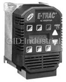
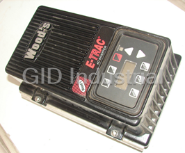
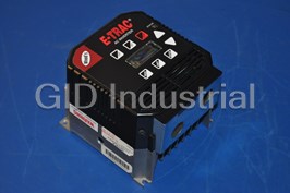
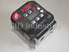
TB Woods XFC2005-0B E-TRAC Micro-Inverter, 230 VAC Input Voltage, 3 HP with NEMA 1 Enclosure, Chassis with Keypad
Part Number
XFC2005-0B
Price
Request Quote
Manufacturer
TB WOODS
Lead Time
Request Quote
Category
PRODUCTS - X
Datasheet

Extracted Text
Form 1075F ® E-trAC XFC SERIES ADDED FEATURES This manual documents the features available with the release of software revision 13.1 / 13.3 or greater. The software revision ® number can be viewed in parameter 02-RVLVL in Level 2 programming. Please note the following changes from previous manuals and other software revisions: XFC Series Quality Made Micro-Inverter in the U.S.A. XFC1000 Series - 1/2 & 1 HP XFC2000 Series - 1/2 through 5 HP XFC4000 Series - 1 through 5 HP Installation, Operation and Maintenance Instructions U U L C ® L ® TB WOOD’S INCORPORATED Chambersburg, Pennsylvania ® ® E-TRAC XFC SERIES MICRO-INVERTER PARAMETER CODE SUMMARY RANGE CUSTOMER PARAMETER DESCRIPTION PAGE (FACTORY SETTING) SETTING RANGE CUSTOMER PARAMETER DESCRIPTION PAGE 0-5 Sec (FACTORY SETTING) SETTING 47-DCBRK DC Brake Time 40 (0.2) Software Revision Note 1 34 02-RVLVL DC Brake 0-15% 03-IRAT Inverter Rated Current Note 1 34 48-DCVLT 40 Voltage Last Fault Note 1 34 07-FLT3 V/Hz Characteristic 0-5 51-VSEL 41 08-FLT2 2nd Fault Note 1 34 Selector (0) 1st Fault Note 1 34 09-FLT1 Torque Boost 0-25% 42 52-BOOST 12-FOUT Motor Output Frequency 0-400 Hz 34 V/Hz Knee 26-960 Hz 53-FKNEE 42 Motor Output Voltage 0-100% of line voltage 35 Frequency (60) 13-VOUT 14-IOUT Motor Output Current 0-60 35 Rated Motor 185-240 59-MVOLT 42 Voltage 370-480 0-200% of Drive Load 35 15-LOAD 03-IRAT Preset Load Torque 30-150% 42 61-LTLF Limit FWD (150) Load Torque 0-200% 35 16-TORQ Preset Load Torque 30-150% 17-TEMP Drive Temperature 0-100¯C 35 42 62-LTLR Limit REV (150) 00-11 21-MODE Input Mode 36 Preset Regenerative 30-110% Note 2 42 63-RTLF Torque Limit FWD (80) Speed Setpoint 0-3 37 24-FSEL Preset Regenerative 30-110% Selector (0) 64-RTLR 42 Torque Limit REV (80) Minimum 0-400 Hz 37 31-FMIN 0-12% Frequency (0) Slip Compensation 43 65-SLIP (0) Maximum 20-400 Hz 37 32-FMAX 0-1 Frequency (60) Current Stability 43 66-STAB (1) 0-400 Hz 33-F2 Preset Frequency #2 37 Timed Overload Trip 0-100% (5) 43 67-TOL Point (0) 0-400 Hz Preset Frequency #3 37 34-F3 0-8 (20) 68-NRST Trip Restart Number 44 (0) 0-400 Hz Preset Frequency #4 37 35-F4 0-60 Sec (40) 69-DRST Restart Time Delay 45 (0) 0-400 Hz Preset Frequency #5 37 36-F5 Analog Meter Output 0-255 (60) 70-MCAL 45 Calibration (Set for 10 VDC) 0-400 Hz Preset Frequency #6 37 37-F6 Analog Meter Output 0-3 (0) 71-METER 45 Selector (1) 0-400 Hz Preset Frequency #7 37 38-F7 0-10 (0) 75-STR Auxiliary Relay Output 46 (2) Minimum Frequency 0-400 Hz 38 39-FTL Motor Overload 0-3 in Torque Limit (10) 77-MOL 47 Input (0) 0-7 41-RSEL Ramp Selector 38 Special 0-9999 (0) 48 81-PRGNO Program Number (0) Acceleration 0.1-600 Sec 42-ACC1 39 0-7 Time #1 (3) Start Options 48 82-START (0) Deceleration 0.1-600 Sec 39 43-DEC1 Display Option 0-3000 Time #1 (3) 50 84-DISP Setting (0) Acceleration 0.1-600 Sec 39 44-ACC2 Security 0-999 Time #2 (1) 87-ACODE 50 Access Code (0) Deceleration 0.1-600 Sec 45-DEC2 39 NOTE: 1. See Section 4.2 for definitions of data Time #2 (1) 2. Models with keypad: Data Code = 0 Deceleration Time in 0.1-30 Sec Models without keypad: Data Code = 3 46-DECTL 39 Torque Limit (1) 3. Level 1 Parameters shown shaded. TABLE OF CONTENTS TABLE OF CONTENTS Section 1 - General Information Page Section 4 - Parameter Descriptions and Programming 1.1 Preface .......................................................................... 1 4.1 Programming................................................................. 33 1.2 Inspection ...................................................................... 1 4.2 Parameter Descriptions................................................. 34 1.3 Model Identification Number.......................................... 2 1.4 Power Specifications ..................................................... 3 Section 5 - Connection Diagrams 1.5 General Drive Specifications ......................................... 4 5.1 AC Line and Motor Connections.................................... 51 5.2 2-Wire Run/Stop Connections....................................... 52 Section 2 - Installation and Enclosure Information 5.3 3-Wire Run/Stop Connections....................................... 52 2.1 General Rules for Installation ........................................ 6 5.4 Analog Speed Input Connections.................................. 53 2.2 Explosion Proof Applications......................................... 7 5.5 MOL Terminal Connections........................................... 53 2.3 Line Starting .................................................................. 7 5.6 Optional Connections .................................................... 54 2.4 Dimensional Data .......................................................... 8 2.5 Input AC Line Requirements ......................................... 12 Section 6 - Troubleshooting 2.5A Single Phase Operation................................................. 13 6.1 Special Indications......................................................... 55 2.6 AC Line Protection......................................................... 14 6.2 Fault Trip Indications ..................................................... 56 2.7 Wiring Practices............................................................. 15 6.3 Resetting a Fault ........................................................... 56 2.8 Reducing Current Surges.............................................. 16 6.4 Fault Codes ................................................................... 57 2.9 Function and Use of Terminals...................................... 18 6.5 Troubleshooting............................................................. 59 2.10 J22 Option Connector.................................................... 20 2.11 Input Terminal Usage .................................................... 21 2.12 J19 Configuration .......................................................... 23 Section 7 - Appendix 7.1 Warranty Statement....................................................... 60 ® 7.2 E-trAC XFC Series Options.......................................... 61 Section 3 - Getting Started 3.1 General Information....................................................... 24 3.2 Digital Keypad ............................................................... 25 3.3 Keypad Operation.......................................................... 25 3.4 Operation Mode............................................................. 26 3.5 Program Mode............................................................... 27 3.6 Status Indicator.............................................................. 28 3.7 Description of Displays.................................................. 28 3.8 Parameter Access ......................................................... 30 3.9 Display Scroll Rate ........................................................ 30 3.10 Restoring Factory Settings ............................................ 30 3.11 Help ............................................................................... 30 3.12 Quick Start..................................................................... 31 SECTION 1 1.3 Model Identification Number GENERAL INFORMATION A systematic numbering system is used to define all E-trAC® models by torque output, input voltage rating horsepower rating and enclosure type. The model number appears on the ship- 1.1 Preface ping carton label and the technical data label of the drive. (See This manual contains the specifications, installation instructions, Table 1.1 below). description of operation, and trouble-shooting procedures for the ® E-trAC XFC1000, XFC2000 and XFC4000 micro-inverter. XF C 2 001-0 B Before installing the drive, read this manual carefully to ensure correct installation and maximum performance. ® E-trAC XFC Series Torque C = Constant 1.2 Inspection Input 1 = 115 VAC Voltage 2 = 230 VAC 4 = 460 VAC A. Upon receipt, unpack and carefully inspect for any damage sustained in transit (depression in the enclosure, damage to Horsepower (See Table 1.1) parts, missing parts). If damage is apparent, the shipping Enclosure A = Chassis (w/o keypad) agent should be notified. B = NEMA 1 (with keypad) C = NEMA 4 (with keypad) B. Remove the terminal access cover (See Section 2.9C), if E = NEMA 1 (w/o keypad) supplied, and inspect for any apparent damage or foreign F = NEMA 4 (w/o keypad) objects. ® This model number describes a constant torque, E-trAC XFC series micro-inverter in a NEMA 1 enclosure with keypad, rated C. Read the technical data label and ensure that the correct 1.0HP, with input voltage of 230 VAC. horsepower and input voltage for the application has been purchased. HP CODE HP 115 VAC 230 VAC 460 VAC 000-5 1/2 X X D. If the inverter is to be stored for a long period of time, re-pack 001-0 1.0 X X X and store in a clean, dry place, free from direct sunlight or 002-0 2.0 X X corrosive fumes, and in a location where the ambient temperature will not be less then -20˚C (-4˚F) nor more than 003-0 3.0 X X +60˚C (+140˚F). 005-0 5.0 X X TABLE 1.1 1 2 1.5 General Drive Specifications Overload Capacity 150% for 60 Seconds Starting Torque Greater than 100% 50/60 Hz Input Frequency (± 10%) Phase Imbalance (3ş only) ±2% 0˚C to +40˚C (NEMA 1/NEMA 4 models) Operating Temperature 0˚C to +50˚C (Chassis model) 90% RH or less, non-condensing Humidity 0.6 G Maximum Vibration 1000 Meters (3,300 Feet) w/o derating Elevation 0.1-400 Hz programmable in 0.05 Hz Frequency Range increments. (0.1 Hz above 99.95 Hz) Control System Voltage Vector PWM 0-5 VDC, 0-10 VDC, 0-20 mA, 4-20 mA, Frequency Command direct or inverted; Digital Keypad; Program Selections Memory Unit; Remote Keypad Unit Frequency resolution 0.05 Hz or 0.1% of maximum frequency 0.24 - 8.85 (230 VAC models) V/Hz Ratio 0.48 - 17.69 (460 VAC models) Acceleration and Programmable 0.1 to 600 seconds to Deceleration Range maximum frequency (2 Each) Maximum / Minimum Separately programmable to 400 Hz Frequency Up to 8 available; programmable to Preset Speeds maximum frequency TABLE 1.3 3 4 1.4 Power Specifications Model - XFC Input 1000-5 1001-0 2000-5 2001-0 2002-0 2003-0 2005-0 4001-0 4002-0 4003-0 4005-0 4005-0 Phases (2) (3) Horsepower 3 --- --- 0.5 1.0 2.0 3.0 5.0 1.0 2.0 3.0 5.0 5.0 5.0 Kilowatt (kW) 3 --- --- 0.37 0.75 1.5 2.2 3.7 0.75 1.5 2.2 3.7 3.7 3.7 Horsepower 1 0.5 1.0 0.33 0.75 1.5 2.0 3.0 --- --- --- --- --- --- Kilowatt (kW) 1 0.37 0.75 0.25 0.55 1.1 1.5 2.2 --- --- --- --- --- --- Output Voltage 3.5 - 230VAC 3.5 - 230VAC 7.0 - 460 VAC 7.0-400 7.0-460 (Three Phase) VAC VAC 3 --- --- 2.2 4.0 7.5 10.6 16.7 2.2 4.1 6.1 9.9 9.9 8.4 Maximum (1) (1) (1) (1) (1) (1) (1) (1) (1) (1) Continuous Output 1 2.2 4.0 1.8 3.1 5.7 7.5 10.5 --- --- --- --- --- Amps (1) (1) Input Voltage (±10%) 115 VAC 208-230 VAC 400-460 VAC 400 VAC 460 VAC Input Amps 3 --- --- 1.9 3.8 7.5 10.4 17.6 2.3 5.1 6.2 10.8 10.8 1 4.5 8.9 2.2 4.4 8.1 14.5 21.0 --- --- --- --- --- Note 1. Value = 1.1 x 03-IRAT (See Section 4.2) Note 2. Models XFC4005-0A, B, E Note 3. Models XFC4005-0C,F TABLE 1.2 SECTION 2 General Specifications (continued) INSTALLATION AND ENCLOSURE DIMENSIONS Up to 60% for 6 sec. with standard DB Dynamic Braking resistor PWM Frequency 7.8/9.2kHz (model dependent) 2.1 General Rules for Installation 1. Keypad 3. Remote Keypad Unit Operating Controls Improper installation of the inverter will greatly affect its life. Be 2. Terminal Strip 4. Program Memory Unit sure to observe the following points when selecting a mounting Red & Green for operation and fault LED Indicators location. VIOLATING THE CONDITIONS LISTED BELOW annunciation (See Section 3.6) MAY VOID THE WARRANTY! 6 digit, backlit LCD with special Keypad Display annunciators and unit symbols A. Do not install the inverter in a place subjected to high Programmed as Fault. Programmable to Auxiliary Relay signal one of ten conditions temperature, high humidity, or excessive vibration. (See Table 1.4 for temperature, humidity and maximum vibration Level 1 - Operator Programming Levels Level 2 - Engineer limits.) B. Mount the drive vertically and do not restrict the air flow to the 15; multi-functional; Input Control Terminals heat sink fins. pull-up or pull-down logic ® C. The E-trAC XFC generates heat. Allow sufficient space UL & CUL Listed Agency Listings around the unit, as shown in Figure 2.1. TABLE 1.3 (continued) MORE THAN 5 IN. Protection Features Ground Fault Startup-all models; NEMA 4 models full-time; MORE MORE NEMA 1 and Chassis models full-time optional FIGURE 2.1 E-TRAC THAN THAN Short Circuit Protected from damage 5 IN. 5 IN. Motor Overload Programmable inverse time overload trip MORE THAN 5 IN. Overvoltage Protected from damage. 500 mS ride-through Protected from damage. 200 mS ride through, Undervoltage load dependent MOL Input Terminal Programmable for N.C. or N.O. contacts. D. When mounting a drive in another enclosure (with the fins Torque Limit Full time four quadrant “Trip-Free” operation inside the enclosure), consult TB Wood’s for enclosure sizing and mounting instructions. Over Temperature Protected from damage, warning display ® E. Do not mount the E-trAC XFC above heat generating TABLE 1.4 equipment, or in direct sunlight. 5 6 2.2 Explosion Proof Applications 2.4 DIMENSIONAL DATA Explosion proof motors that are not rated for inverter use lose their certification when used for variable speed. Due to the (SEE NOTE) .25 many areas of liability that may be encountered when dealing 4.13 4.84 (6) with these applications, the following statement of Company (105) (123) .21 Policy applies: .13 3.70 (5) (3) (94) TB Wood’s Incorporated AC Inverter products are sold for suitability with explosion proof AC motors rated for use with PWM inverters. These motors must be UL listed for use with either TB Wood’s AC inverters or with PWM inverters and used within the specified speed ranges and 5.40 carrier frequencies. TB Wood’s accepts no responsibility (137) 6.26 for any direct, incidental or consequential loss, cost or (159) damage associated with the misapplication of our AC products in these applications. In any misapplication, the purchaser expressly agrees to assume all risk of loss, .22 DIA. TYP. cost or damage that may arise. TB Wood’s Incorporated .49 (5.5) will not knowingly approve the application of their AC (12) inverters with motors not rated for such applications. .875 DIA. (22) 2 1/2 INCH 2.3 Line starting CONDUIT ENTRY 3.31 ® HOLES E-trAC XFC is designed to provide controlled starting and (84) stopping of AC motors by use of the keypad or external con- tacts connected to the control terminal strip. The drive may DIMENSIONS also be started by using a maintained contact (2-wire oper- 1.17 INCHES ation) and applying AC power to terminals L1, L2, and L3. To 1.35 (30) (MM) prevent accidental starting of the motor, the inverter has line- (34) start-lockout as a standard feature. This provision can be NOTE: CHASSIS MODELS SUPPLIED WITHOUT PLASTIC COVERS AND CONDUIT PLATES. DEPTH = 4.68 (119) defeated by programming 82-START (See Section 4.2). THE INVERTER MAY BE STARTED ONCE EVERY TWO (2) MINUTES IN THE LINE STARTING MODE. 0.5 HP 115 VAC 0.5 - 1.0 HP 230 & 460 VAC FIGURE 2.2 7 8 2.4 DIMENSIONAL DATA (continued) 2.4 DIMENSIONAL DATA (continued) 5.50 (SEE NOTE) .25 4.84 (140) (6) (123) .21 5.07 .13 (5) (129) (3) 5.40 6.26 (137) (159) .22 DIA. TYP. .49 (5.5) (12) .875 DIA. (22) 2 1/2 INCH CONDUIT ENTRY 3.31 HOLES (84) DIMENSIONS 1.48 INCHES 2.11 (38) (MM) (54) 3 & 5 HP NEMA 1 Models NOTE: CHASSIS MODELS SUPPLIED WITHOUT PLASTIC COVERS AND CONDUIT PLATES. DEPTH = 4.68 (119) FIGURE 2.4 1.0 HP 115 VAC 2.0 HP 230 & 460 VAC FIGURE 2.3 9 10 2.4 DIMENSIONAL DATA (continued) WARNING DISCONNECT ELECTRICAL SUPPLY BEFORE SERVICING THE ELECTRICAL SYSTEM. AVERTISSEMENT COUPER L’ALIMENTATION AVANT D’ENRERENORE LE DEPANNAGE DU SYSTEME ELECTRIQUE. 2.5 Input AC Line Requirements The allowable AC line voltage fluctuation is specified in Section 1.4. A supply voltage above or below these limits will cause the inverter to trip out with either an overvoltage or an undervoltage fault. ® NOTE: If the source of the AC power to the E-trAC XFC is greater than ten times the kVA rating shown in Table 2.1, an isolation transformer or line inductors are recommended. Consult the factory for help in sizing the inductors. INPUT POWER TRANSFORMER RATINGS Rated Horsepower 0.5 1.0 2.0 3.0 5.0 Minimum kVA Rating 1.0 2.0 4.0 5.0 8.0 TABLE 2.1 ® NOTE: Caution must be exercised when applying E-trAC XFC ® micro-inverters on low line conditions. For example, an E-trAC XFC2000 series micro-inverter will operate properly on a 208 VAC line; however, the maximum output voltage will be limited to 208 VAC. If the motor is rated for 230 VAC line voltage, FHP THROUGH 3 HP – 230V – NEMA 4 1HP THROUGH 5HP – 460V – NEMA 4 FIGURE 2.5 11 12 2.6 AC Line Protection higher motor currents and increased heating will result. Ensure that the voltage rating of the motor matches the applied line The user must provide either a circuit breaker or a fused voltage. If other than 60 Hz output is desired, proper volts/hertz disconnect switch on the input AC line in accordance with all can be programmed into the inverter by the 53-FKNEE and 32- applicable electrical codes. The following rules should be used FMAX parameters. If you are unsure about this feature, consult to select the correct size of the input line fuses or circuit breaker. the factory. Phase voltage imbalance of the input AC source can cause A. Sizing unbalanced currents and excessive heat in the input rectifier ® The E-trAC XFC micro-inverter is able to withstand a 150% diodes and in the DC bus capacitors of the inverter. Phase imbalance can also be damaging to motors running directly overload for 60 seconds. For applications with short intermittent loads over 100%, select a fuse or magnetic trip circuit breaker across the line. rated at 1.5 times the input current rating of the drive. For CAUTION: NEVER USE POWER-FACTOR CORRECTION applications with repetitive load peaks above 100% select 1.7 ® CAPACITORS ON THE E-trAC XFC MOTOR TERMINALS times the input current (See Section 1.4, Table 1.2 for input M1, M2, AND M3, OR DAMAGE TO THE SEMI-CON- current ratings). Minimum voltage rating for the protection DUCTORS WILL RESULT. device should be 250 VAC for XFC1000 & XFC2000 models, and 600 VAC for XFC4000 models. A. Single Phase Operation ® B. Fuse Type XFC2000 Series E-trAC micro-inverters are designed for both three phase and single phase input power. If operating with The XFC inverter is able to withstand a 150% overload for 60 single phase power, use line terminals L1 and L2. The output of seconds. For maximum protection of the inverter, use the fuses the drive will always be three phase. See Section 1.4 for listed in Table 2.2. Recommended suppliers are Bussman for applicable derating when using single phase input power and 230VAC and 460VAC. Section 5, Figure 5.1 for proper power connections. Do not Model Fuse Model Fuse connect single-phase motors to the inverter output terminals M1, M2 or M3. XFC1000-5 KTK-7 or KTK-R-7 XFC2005-0 KTK-40 XFC1001-0 KTK-15 or KTK-R-15 XFC4001-0 KTK-4 or KTK-R-4 XFC2000-5 KTK-3 or KTK-R-3 XFC4002-0 KTK-7 or KTK-R-7 XFC2001-0 KTK-10 or KTK-R-10 XFC4003-0 KTK-10 or KTK-R-10 XFC2002-0 KTK-15 or KTK-R-15 XFC4005-0 KTK-15 or KTK-R-15 XFC2003-0 KTK-25 or KTK-R-25 TABLE 2.5 13 14 2.7 Wiring Practices 2. Power delivered from variable frequency drives contains high frequencies which may cause interference with other equipment. A. Applicable Codes Control wiring should not be run in the same conduit or raceway with power or motor ® All E-trAC XFC models are Underwriters Laboratories, Inc. wiring. TM (UL ) and Canadian Underwriters Laboratories (CUL™) listed and therefore comply with the requirements of National Electrical Code (NEC) and the Canadian Electrical Code (CEC). C. Control Wiring TM TM Installations intended to meet UL and CUL requirements must follow the instructions provided herein as a minimum This is wiring connected to the control terminal strip (15 standard. Where local codes exceed these requirements, they terminals). It must be selected as follows: ® must be followed. Refer to the E-trAC technical data plate and 1. Shielded wire is recommended to prevent electrical noise the motor nameplate for electrical data. interference from causing improper operation or nuisance tripping. Connect the shield to terminal CM (control common) ® on the E-trAC XFC control terminal strip only. B. Power Wiring TM 2. Use only UL recognized wire. Power wiring are those wires which are connected to terminals 3. Wire voltage rating must be a minimum of 300 V for 230 VAC L1, L2, L3, M1, M2, and M3. Power wiring must be selected as systems, and 600 V for 460 VAC systems. This is Class 1 follows: wire. 4. Never run the control wiring in the same conduit or raceway TM 1. Use only UL recognized wire. with power wiring. See NOTES above. 2. Wire voltage rating must be a minimum of 300 V for 230 VAC systems, and 600 V for 460 VAC systems. 2.8 Reducing Current Surges and Voltage Transients 3. Wire gauge must be selected based on 125% of continuous Inrush currents to the coils of magnetic contactors, relays and output current rating of the drive. Wire gauge must be solenoids associated with, or in close proximity to, the inverter selected from wire tables for 60˚C or 75˚C insulation rating, can induce high current spikes in the power and control wiring and must be of copper construction. Refer to Table 1.2 for causing faulty inverter operation. If this condition occurs, a continuous output ratings. snubber network, consisting of a series resistor and capacitor for 4. Grounding must be in accordance with NEC and the CEC. AC loads, or a free-wheeling or flyback diode for DC loads, should be placed across the relay coil. NOTES: 1. Never connect input AC power to the motor output terminals M1, M2 and M3 or damage to the drive will result. 15 16 2.9 Function and Use of Terminals For 115 VAC loads, TB Wood’s part number U4785, or ITW Quencharc part number #104M06QC150 is suitable. Refer to Section 5 - Connection Diagrams for power and control wiring examples. For magnetic contactors, relays and solenoids which are energized from a DC source, a free-wheeling diode should be A. Power Circuit Terminals used. The diode should be a high-speed, fast recovery type. ® The power terminals are located on the E-trAC power module, Connect the diode across the coil with the cathode end toward and are labeled L1, L2, and L3 for incoming three phase AC line the positive power source. The diode current and voltage power, and M1, M2, and M3 for the motor connections. Two should be selected by the following formula: ground connections (GND) are located on the upper left-hand side of the end plate on NEMA 1 models and on the heatsink on Coil Capacity (VA) the chassis model. The screws are green and must be _________________________ Diode Current Rating (A) connected to earth ground in accordance with the NEC. Note Rated Voltage of Coil (V) that for NEMA 4 units, L1, L2, and L3 must be run through the Ground Fault CT to maintain full-time ground fault Diode Voltage Rating Rated Voltage of Coil (V) x 2 protection (see Figure 2.9). B. Control Terminals The control terminals are located on the bottom edge of the inverter’s control board. See Figure 2.8 and Section 2.11. These terminals are available for use with external devices. AC DC + NOTE: Control input signals must not exceed 24 VDC ± 20% potential to ground. 1. Control terminal input impedance: * VIN terminal - 100 kΩ (0-5/10 VDC input) * VIN terminal - 250 Ω (0/4-20 mA input) * FWD, REV, PS1, PS2, PS3, MOL, - 4.5 kΩ Freewheeling R RC Type Coil Coil Diode Snubber C 2. Logic Input Levels: LOGIC TYPE PULL-UP PULL-DOWN - ACTIVE 10 - 24 VDC 0 - 3 VDC INACTIVE 0 - 3 VDC 10 - 12* VDC FIGURE 2.6 *Consult Factory Application Note #AN1 for higher voltages J19 selects active High or Low control inputs. (See Section 2.12) 17 18 ‡ ‡ C. Terminal Access Cover Removal NEMA 1 versions of E-trAC XFC are designed to prevent accidental removal of the terminal access cover. Enhancements CM MET CM VIN REF FWD REV PS3 PS2 PS1 V+ MOL NO RCM NC to the mounting provisions have added to the protection against damage and injury to personnel. The mounting meets UL and NEC specifications for safety. To remove the access cover, loosen the two 8/32 screws (U1294) mounted at 45° angles at the lower corners of the access cover. Note that when replacing M2 L1 L2 L3 M1 M3 the screws, a snug fit only is required. Do NOT torque the screws or damage to access cover may result. AC LINE CONTROL J19 L1, L2, L3 TERMINALS MOTOR J22 M1, M2, M3 FIGURE 2.8 FIGURE 2.7 D. NEMA 4 Cover Installation To assure the environmental integrity of the NEMA 4 models, unused conduit fittings must be sealed. A conduit plug is pre- installed in the upper conduit hole. Also, the cover screws must be properly tightened. After all electrical connections are made, swing the cover closed and torque all four (4) cover screws to a maximum torque of 10-15 in.lb. Tighten alternate corners to assure even compression of the enclosure gasket. FIGURE 2.9 19 20 DESCRIPTION OF TERMINALS 2.10 J22 Option Connector Digital inputs normally used for preset speed selection. Jumper J19 PS1 ® Connector J22, located on the right side of the E-trAC XFC selects pull-up or pull-down logic (see Section 2.12). PS3 can define PS2 micro-inverter, is used to interface with a number of external as a Run/Jog selector by 21-MODE or as the ART selector by 41- PS3 RSEL. Eight preset speeds are available if all 3 inputs are used, and options (see Section 7.2). Keypad options interfaced thru J22 four are available if PS3 is redefined via 21-MODE or 41-RSEL. may be mounted up to 300 feet from the drive. Programmer options allow the storage of up to ten (10) separate parameter PS1 PS2 PS3 EFFECTIVE SPEED REFERENCE sets. 0 0 0 Basic speed setpoint (keypad or terminals) 1 0 0 33-F2 0 1 0 34-F3 1 1 0 35-F4 2.11 Input Terminal Usage 0 0 1 36-F5 ® The E-trAC XFC series micro-inverter has a 15 position control 1 0 1 37-F6 terminal block. Some functions are defined by the setting of 0 1 1 38-F7 jumper J19, while others are defined by programming. Refer to 1 1 1 32-FMAX Section 5 - Connection Diagrams and Figure 2.8. PS1 0 0 N/A Basic speed setpoint (keypad or terminals) DESCRIPTION OF TERMINALS PS2 1 0 N/A 33-F2 CM Circuit Common, isolated from ground. 0 1 N/A 34-F3 Analog meter output providing a 0 to 10 VDC (1 mA Max.) signal propor- 1 1 N/A 35-F4 MET tional to Output Frequency, Load, or Current via setting of 71-METER. The output may be calibrated by programming 70-MCAL while running. Normally open contact for the Auxiliary Relay. Will close when the NO relay is activated. Rating is 115 VAC at 1 Ampere Analog speed input, J19 jumper selectable for 0-5 VDC, 0-10 VIN VDC or 0/4-20 mA DC. A 4 mA offset is programmed by 24-FSEL. Auxiliary relay common terminal. Factory programmed as a Fault 5.2 VDC reference voltage, 3 mA maximum load. RCM relay but may be set to activate under one of ten conditions. See USE ONLY FOR A FREQUENCY CONTROL POTENTIOMETER Section 4.2, 75-STR. REF (5 kΩ Recommended) Normally closed contact for the Auxiliary Relay. Will open when the NC Digital input for Forward operation. May be programmed for relay is activated. Rating is 115 VAC at 1 Ampere FWD maintained (standard) or momentary contacts by 21-MODE. Digital input for Reverse operation. May be programmed for REV TABLE 2.3 (continued) maintained (standard) or momentary contacts by 21-MODE. Positive nominal 12 VDC voltage. Only for use with digital V+ inputs. (See Section 5) NO OTHER USE IS ALLOWED. Motor Overload Relay input. May be configured to generate a fault on opening or closing. May also be configured to command MOL a Coast-To-Stop on opening or closing. See section 4.2, 77-MOL. TABLE 2.3 21 22 2.12 J19 Configuration SECTION 3 GETTING STARTED J19 is a pin-jumper selector located below the terminal block on the left-hand side of the control board (See Figure 2.8). It has five 3.1 General Information (5) positions and two movable shorting jumpers. One jumper ® selects the analog speed reference used and the second jumper * Some E-trAC XFC Series micro-inverters do not include a selects the active state (High or Low) of the digital inputs. A pair of digital keypad as standard equipment. These models are small needle nose pliers will prove useful for moving these programmed to operate via the control terminal strip. They may jumpers. REMOVE AC POWER AND WAIT FOR ALL be re-programmed using the optional keypad / programmer INDICATORS TO GO OUT BEFORE CHANGING THIS JUMPER. options outlined in Section 7.2. ® * Your E-trAC XFC micro-inverter is pre-programmed to run a Analog Reference Selection (24-FSEL selects direct or inverse operation) standard 4-pole AC induction motor; in many cases no This configures the drive to accept an external 0-10 VDC additional programming is required. speed reference signal. Input impedance is 100 kΩ. * The advanced digital keypad controls all operations of the inverter. The eight input keys allow “Press and Run” operation This configures the drive for either a 0-20 mA or a 4-20 mA of the motor and straight forward programming of the input from an external source. 0 or 4 mA is selected by 24- parameters. To simplify the programming further, the FSEL. parameters are separated into two Program Levels: (DEFAULT SETTING) This configures the drive for an LEVEL 1 Easily entered by pressing the PROG key at any time. external 0-5 VDC signal, or a speed potentiometer powered Limits access to the most commonly used parameters from the REF terminal on the control terminal strip. for operator convenience. Digital Input Logic Selection LEVEL 2 Accesses all parameters including those in Level 1. Used when the more advanced features are needed. It is entered by pressing and holding the SHIFT key This configures the digital inputs for pull-down logic. That is, then pressing the PROG key. active when connected to terminal CM. Inputs are high, and are pulled low to activate. Parameters may only be programmed when the drive is stopped, with the exception of 70-MCAL which may be programmed at any time (See Section 4.2). (DEFAULT SETTING) This configures the digital inputs for pull-up logic. That is, active when connected to terminal V+, or to an external power supply with it’s common connected to CM. Inputs are low and require a positive voltage to activate them. 0 to 3 VDC is INACTIVE, 10 to 24 VDC is ACTIVE. 23 24 3.2 Digital Keypad 3.4 Operation Mode (RUN and STOP modes) KEY FUNCTION Initiates forward run when pressed momentarily. If the drive is running in reverse when FWD is pressed, it will decelerate to zero FWD speed, change direction, and accelerate to the set speed. STATUS Initiates reverse run when pressed momentarily. If the drive is REV running in forward when REV is pressed, it will decelerate to zero speed, change direction, and accelerate to the set speed. Causes a Ramp-To-Stop when pressed. Programmable to Coast- STOP To-Stop by 41-RSEL. In the Stop mode, pressing this key increases the desired running speed of the drive. In the Run mode, pressing this key increases Hz FWD the actual running speed of the drive. Setting resolution is 0.05 Hz UP up to 99.95 Hz and 0.1 Hz above this frequency. The display will scroll at an increased rate after holding the key for five seconds. Pressing SHIFT while holding the UP Arrow bypasses the delay. In the Stop mode, pressing this key decreases the desired running speed of the drive. In the Run mode, pressing this key decreases the actual running speed of the drive. Setting resolution is 0.05 Hz up to DOWN 99.95 Hz and 0.1 Hz above this frequency. The display will scroll at an increased rate after holding the key for five seconds. Pressing SHIFT while holding the DOWN Arrow bypasses the delay. In the Stop or Run modes, pressing this key will store the selected frequency as the initial operating frequency when the FIGURE 3.1 ENTER inverter is powered up. The frequency is maintained until another frequency is entered. 3.3 Keypad Operation In Run mode, pressing this key will access Level 1 Parameters for Viewing only. Holding SHIFT and then pressing PROG will When 21-MODE is set to 0 or 10, start/stop and speed access Level 2. Any attempt to program (other than 70-MCAL) will PROG commands are accepted from the keypad. The keys are used to result in a display that shows “– – – – ”. operate the inverter as described in Section 3.4 In Stop mode, programming is allowed in both Level 1 and Level 2. See Section 3.5. TABLE 3.1 25 26 FWD REV PROG STOP SHIFT ENTER 3.5 Program Mode 3.6 Status Indicator The STATUS indicator consists of two LEDs, one green and one KEY FUNCTION red located in the upper right corner of the control board. They When in Stop mode, pressing this key will enter the Program mode are visible through a lens in the upper right corner of the keypad at Level 1. Pressing the key at any time while in the Program mode on NEMA 1 or NEMA 4 models. The following table defines the will return the unit to the Operation mode. Pressing and holding PROG STATUS indicator state for the various operating conditions of SHIFT while pressing PROG will access Level 2. If an Access Code has been invoked, it must be entered to change Data Code. See the inverter. Section 4.2, 87-ACODE. In the Program mode, pressing this key will move forward through STATUS INDICATOR OPERATING CONDITION the successive parameters. If the PRG indicator is flashing it UP increases the Data Code. The ENTER key must be pressed to COLOR DURATION store the Data Code. Green & Red Continuous Power on, restart (2 Seconds) In the Program mode, pressing this key will move backward Red Continuous Stop, running in torque limit through the successive parameter addresses. If the PRG indicator Green Continuous Run DOWN is flashing it decreases the Data Code. The ENTER key must be pressed to store the Data Code. Green & Red Flashing Running in and out of torque limit Green Flashing Running in and out of an overvoltage or NOTE: If the PRG indicator is flashing, momentarily pressing and undervoltage condition releasing both the UP and DOWN arrows simultaneously will return the Data Code to factory defaults. Press ENTER to store the new Red Flashing Drive faulted, emergency stop, line start code. lockout or low voltage Pressing this key while a parameter is displayed will allow that TABLE 3.3 parameter to have its Data Code changed by use of the UP and SHIFT DOWN arrow keys. This key must be pressed after the Data Code has been changed to store the new code. The display will show STOred for one ENTER second indicating that the Data Code has been entered into 3.7 Description of Displays memory. The custom, back-lit, LCD display provides information on drive TABLE 3.2 operation and programming. The four large 7-segment displays show drive output and programming data. The two smaller digits are used to indicate parameter numbers in the Program mode. Special symbols and displays provide further clarification of drive operation. Figure 3.2 shows all segments displayed. In normal operation only those segments that are active are displayed. 27 28 3.8 Parameter Access OV UV LIM OC TEMP DB * When the PROG (or SHIFT-PROG) key is pressed after the rpm application of power or a fault reset, 21-MODE will always be Hzhs FWDREV the first parameter displayed. See Section 4.1 for programming AV%C PRG SET instructions. * If a different parameter is accessed and the Program mode is FIGURE 3.2 exited, that parameter will be the point of entry the next time the Program mode is accessed. Table 3.4 lists the special annunciators and their meaning. ® * The E-trAC XFC will remember a different “last parameter accessed” for Levels 1 and 2. SYMBOL DESCRIPTION * If no key is pressed for 10 minutes while in the Program mode, FWD Forward direction commanded the drive will automatically revert back to the operating mode. REV Reverse direction commanded 3.9 Display Scroll Rate Program mode selected (continuous) PRG Data Code may be changed (flashing) Three scroll rates are used to speed data entry. * If either the UP or DOWN arrow is pressed and held for five SET Drive is stopped, or is having the running frequency set seconds, the scroll rate will increase. OV Drive is in an overvoltage condition * If the SHIFT key is momentarily pressed while pressing one of UV Drive is in an undervoltage condition the arrow keys, the five second delay will be bypassed. LIM Drive is running in torque limit * If the SHIFT key is pressed a second time while pressing an arrow key the display will scroll at the fastest rate. Drive is in (flashing) or has tripped (continuous) due to an OC overcurrent condition Drive is near (flashing) or has tripped (continuous) due to an over 3.10 Restoring Factory Settings TEMP temperature condition * Whenever a parameter Data Code is being changed (noted by The standard Dynamic Brake circuit is active DB PRG flashing) the original factory setting for that parameter can rpm Revolutions per minute indication be restored by pressing and releasing both the UP and DOWN arrows simultaneously and then pressing the ENTER key. Frequency in Hertz Hz * To restore ALL parameters to factory settings, or recall a Time in hours h previously stored parameter set, see Section 4.2 81-PRGNO. Time in seconds s Output current indication in Amperes A 3.11 Help Output voltage indication in Volts * For Application Assistance, call TB Wood’s Electrical Applica- V tion Engineering at 800-789-6637. Display is in percent of units % Degrees centigrade C TABLE 3.4 29 30 3.12 Quick Start C. The factory settings are for keypad only operation in the forward direction. This means that the REV key is disabled. This section is for operators with simple applications who would Press the FWD key, the display will change to: like to get up and running quickly and with a minimum amount of reading of the manual. Be sure to read sections 3.1 through ® 3.8 before proceeding. In many cases your E-trAC XFC will perform perfectly without making any changes to the factory ® settings. This section assumes that the E-trAC XFC has either Hz FWD a standard keypad or remote keypad attached. If remote operators are being used, substitute the speed potentiometer for the UP and Down arrows and the remote Run/Stop switch for the FWD key in the following instructions. FIGURE 3.4 A. Perform all procedures for installation as specified in D. Press the UP Arrow to increase the desired running frequency. Section 2 - Installation Instructions. When the display gets to 0.1 Hz, the inverter will start to RE-VERIFY THAT THE PROPER VOLTAGE IS produce an output. When the motor starts to turn, check the CONNECTED TO THE INVERTER BEFORE APPLYING rotation. If the motor is turning in the wrong direction, PRESS POWER. FAILURE TO DO THIS CAN RESULT IN STOP, REMOVE AC POWER AND WAIT FOR ALL PERSONAL INJURY AND EQUIPMENT FAILURE! INDICATORS TO GO OUT. After the STATUS indicator has gone out, reverse any two of the motor leads at M1, M2 or M3. B. Apply AC power to the input terminals. For about two E. The length of time that the UP Arrow is pressed determines seconds the display will show all segments active (See the scroll rate of the display. After it is held for five seconds, Figure 3.2). The STATUS indicator will then turn red the rate of change will increase. The five second time can be (indicating a Stop condition) and the display will change to: circumvented by momentarily pressing the SHIFT key while holding the UP (or DOWN) Arrow. F. The inverter is preset to run a “typical” NEMA B 4-pole induction motor to a maximum speed of 60.00 Hz with both Acceleration and Deceleration times set to 3.0 seconds. See the Parameter Code Summary (inside front cover) for a Hz complete list of all factory settings. SET G. Use the Arrow keys to set the proper running speed of the FIGURE 3.3 motor and the FWD and STOP keys to control it’s operation. 31 32 SECTION 4 4.2 Parameter Descriptions PARAMETER DESCRIPTIONS AND PROGRAMMING ® This section provides functional descriptions of all E-trAC XFC parameters. Level numbers with an asterisk (*) indicate parameters that cannot be programmed, only viewed. Level 1 - Accesses only basic operator parameters. Level 2 - Accesses all parameters including those in Level 1. Note: Setting resolution is 0.05 up to 99.95 and 0.1 above this point unless otherwise noted. 4.1 Programming Parameter Units Level Refer to Figures 3.1 and 4.1. To change the default Data Code in a given parameter: 02-RVLVL - Software Revision L2* This parameter holds the identification code of the Read Only A. Press the STOP key to stop the inverter if running. Memory. B. Press the PROGram key to enter Level 1 Program mode. To enter Level 2 press and hold the SHIFT key and then the PROGram key. The PRG indicator will turn on. 03-IRAT - Inverter Rated Current [A] L2* C. Press the UP/DOWN arrow keys to access the desired This defines the nominal output current of the inverter and parameter. The parameter number will be displayed in the serves as the 100% reference for all current measurements. upper left corner of the digital display. Continuous drive capacity is 1.1 times 03-IRAT. D. Press the SHIFT key to allow the Data Code to be changed. PRG will start to blink. 07-FLT3 - Last Fault L1* E. Press the UP/DOWN arrows to select the new Data Code. 08-FLT2 - Second Fault L2* F. Press the ENTER key to store the new Data Code. The 09-FLT1 - First Fault L2* display shows STOred for one second. This defines the most recent faults. The two left most digits G. Press the PROGram key to exit the Program mode or the are the fault code, and the right most is elapsed time in 0.1 hr UP/DOWN arrows to select a new parameter. increments, since the last restart of the drive, 0.9 hours max. See Section 6.2. 12-FOUT - Motor Output Frequency [Hz] L1* Inverter output frequency (Hz) applied to the motor. Hz PRG FIGURE 4.1 33 34 Parameter Units Level Parameter Units Level 21-MODE - Input Mode L1 13-VOUT - Motor Output Voltage [%] L1* The MODE parameter defines the source for speed reference Motor output voltage calculated as a percent of applied line and Run/Stop control input. input voltage. DATA SPEED START/STOP CODE CONTROL CONTROL 14-IOUT - Motor Output Current [A] L1* 0 KEYPAD KEYPAD (FWD Only) Motor phase current computed to an accuracy of ± 20%. 10 KEYPAD KEYPAD (FWD & REV) 1 VIN TERMINAL KEYPAD (FWD Only) 15-LOAD - Drive Load [%] L1* True part of motor current. Output current measurement with 11 VIN TERMINAL KEYPAD (FWD & REV) motor power factor applied. Accuracy is ± 20%. Load reading TERMINALS 2 KEYPAD is positive in motoring mode, and negative in regenerative (2-Wire Maintained Contact) mode. TERMINALS 3 VIN TERMINAL (2-Wire Maintained Contact) 16-TORQ - Load Torque [%] L1* TERMINALS 4 KEYPAD (3-Wire Momentary, RUN/JOG via PS3) Torque output of the motor. Computed from 15-LOAD, taking into account constant horsepower operation when 12-FOUT is TERMINALS 5 VIN TERMINAL (3-Wire Momentary, RUN/JOG via PS3) greater than 53-FKNEE. Regenerative torque is shown with a negative sign. EMOP TERMINALS 6 (2-Wire, See Section 5.6 and table below) 17-TEMP - Drive Temperature [˚C] L1* EMOP TERMINALS 7 Inverter heatsink temperature. The inverter will turn off when (3-Wire, See Section 5.6 and table below) this temperature exceeds its maximum allowed temperature. This display is accurate to ±3˚C. EMOP Control Terminal Logic Table DESCRIPTION FWD REV PS1 PS2 STOP 0 0 X X Speed = 0 1 1 X X FWD Decrease 1 0 1 X FWD Hold 1 0 0 0 FWD Increase 1 0 0 1 REV Decrease 0 1 1 X REV Hold 0 1 0 0 REV Increase 0 1 0 1 X = “Don’t Care” 35 36 Parameter Units Level Parameter Units Level 24-FSEL - Speed Setpoint Selector L2 39-FTL - Minimum Frequency in Torque Limit [Hz] L2 Selects the speed setpoint characteristics and the offset if This parameter sets the lowest frequency that the drive will required. Also see J19 Selection (Section 2.12). decelerate to when in torque limit. If the load is large enough to drive the inverter below this threshold, the drive will trip on overcurrent. DATA OPERATION OFFSET INPUT SIGNAL CODE 1. The rate of deceleration is set by 46-DECTL. 2. Programmable from 0 to 400 Hz. Factory set for 10 Hz. 0 DIRECT 0 0-10 VDC, 0-5 VDC, 0-20 mA 3. To disable Torque Limit, set this to a Data Code greater 1 INVERSE 0 0-10 VDC, 0-5 VDC, 0-20 mA than 32-FMAX. 2 DIRECT 20% 4-20 mA 3 INVERSE 20% 4-20 mA 41-RSEL - Ramp Selector L2 Selects the Acceleration and Deceleration ramps that control NOTE: DIRECT = maximum output (32-FMAX) at maximum input. the motor and also enables the coast-to-stop function. INVERSE = minimum output (31-FMIN) at maximum input. DATA DEFINITION CODE 31-FMIN - Minimum Frequency [Hz] L1 0 Sets the minimum frequency to the motor. Programmable Ramp-to-stop with 42-ACC1 and 43-DEC1 active. from 0 to 400 Hz. Minimum programmable output frequency is 42-ACC1/43-DEC1 active in Forward, 44-ACC2/45-DEC2 active in 1 Reverse. 0.1 Hz. 42-ACC1/43-DEC1 active when the output frequency is less than 2 preset frequency 37-F6, 44-ACC2/45-DEC2 active when output 32-FMAX - Maximum Frequency [Hz] L1 frequency is equal to or greater than 37-F6. Sets the maximum frequency to the motor. Programmable When 21-MODE is programmed for 2, 3 or 6, PS3 is re-defined as from 20 to 400 Hz. the Alternate Ramp Time (ART) selector. When this terminal is 3 Consult motor manufacturer if frequency is in excess of active, 44-ACC2 and 45-DEC2 are selected. Note that PS3 cannot nameplate rating. be used as a Preset Speed selector when 41-RSEL = 3 (See Table 2.2 and 21-MODE). 4 Same as 0, except coast-to-stop is selected when stopping. 33-F2 through 38-F7 - Preset Frequencies [Hz] L2 Same as 1, except coast-to-stop is selected when stopping. 5 Programmable from 0 to 400 Hz. Selected with input terminals PS1, PS2 and PS3 (See Sections 2.11 & 5.6). May be set to 6 Same as 2, except coast-to-stop is selected when stopping. a frequency greater than 32-FMAX, but the output WILL NOT Same as 3, except coast-to-stop is selected when stopping. 7 exceed 32-FMAX when running. Consult motor manufacturer if frequency is in excess of motor name- plate rating. 37 38 Parameter Units Level Parameter Units Level 42-ACC1 - Acceleration Time #1 [s] L1 47-DCBRK - DC Brake Time [s] L2 Sets the length of time to accelerate from 0 Hz to 32-FMAX. This is the time in seconds that DC current will be applied to Programmable from 0.1 to 600 seconds. Extremely short the motor windings with the following conditions: acceleration times may result in nuisance fault trips. (See 41-RSEL) 1. Data Code = 0 A. DC braking disabled in all modes. 43-DEC1 - Deceleration Time #1 [s] L1 Sets the length of time to decelerate from 32-FMAX to 0 Hz. 2. Data Code = 0.05 - 4.95 (Timed DC braking) Programmable from 0.1 to 600 seconds. Extremely short A. In terminal strip Stop/Start, when both FWD and REV deceleration times may result in nuisance fault trips or may terminals are active. require external dynamic braking resistor (consult factory). B. In FWD or REV run mode and the speed reference is (See 41-RSEL) reduced to less than 0.1 Hz. C. A Stop command is given and the output frequency 44-ACC2 - Acceleration Time #2 [s] L2 decelerates to less than 0.1 Hz. Alternate Acceleration Ramp. Sets the length of time to accelerate from 0 Hz to 32-FMAX. Programmable from 0.1 to 3. Data Code = 5 (Continuous DC braking) 600 seconds. Extremely short acceleration times may result A. In terminal strip Start/Stop, as long as both FWD and in nuisance fault trips. REV terminals are held active. (See 41-RSEL) B. In FWD or REV run mode and the speed reference is reduced to less than 0.1 Hz. 45-DEC2 - Deceleration Time #2 [s] L2 C. There is no DC braking after a normal deceleration to Alternate Deceleration Ramp. Sets the length of time to stop. decelerate from 32-FMAX to 0 Hz. Programmable from 0.1 to 600 seconds. Extremely short deceleration times may result 48-DCVLT - DC Brake Voltage [%] L2 in nuisance fault trips or may require external dynamic braking This controls the amount of DC voltage applied to the motor resistor (consult factory). windings by 47-DCBRK. Programmable from 0 to 15% of the (See 41-RSEL) input voltage rating. Factory setting is model dependant. 46-DECTL - Deceleration Time in Torque Limit [s] L2 CAUTION: If DC Braking is used as a holding brake, This parameter sets the deceleration rate when the drive is excessive motor heating may result. operating in torque limit mode. Programmable from 0.1 to 30 seconds. It also serves as the acceleration rate when the drive is in torque limit due to a regenerative condition. (See 39-FTL) 39 40 Parameter Units Level Parameter Units Level 51-VSEL - V/Hz Characteristic Selector L2 52-BOOST - Torque Boost [%] L1 Three V/Hz characteristics (constant torque, pump and fan This parameter increases motor voltage at low speed as a curves) and two starting torque boost features may be percent of nominal voltage to increase the starting torque of selected. the motor. Voltage boost will linearly decrease with increasing speed. Default Boost settings vary between models. DATA NOTE: Care must be exercised with this adjustment. Too DESCRIPTION CODE much torque boost may cause excessive motor currents and motor heating. Use only as much boost as is necessary Linear V/Hz, with Auto-Boost, used with constant torque to start the motor. Auto-Boost may be selected at parameter applications. With Auto-Boost, the optimum boost will be selected 0 depending on load and motor conditions, parameter 52-BOOST sets 51-VSEL to provide the optimum value of boost to suit the the maximum boost applied. load automatically. 1 Linear V/Hz, with constant boost fixed by 52-BOOST. 53-FKNEE - V/Hz Knee Frequency [Hz] L2 Mixed (linear/quadratic) V/Hz, with Auto-Boost, typical of pumping 2 This parameter sets the point on the frequency scale at which applications. the output is at full line voltage. Programmable from 26 to 960 3 Mixed V/Hz, with constant boost fixed by 52-BOOST. Hz. This is normally set at the base frequency of the motor but 4 Quadratic V/Hz, with Auto-Boost, for fan-law applications. may be increased to enlarge the constant torque range on 5 Quadratic V/Hz, with constant boost fixed by 52-BOOST. special motors. Setting FKNEE to a higher value can reduce motor losses at low frequencies. 100% 100% 59-MVOLT – Rated Motor Voltage [V] L2 This sets the voltage the inverter delivers to the motor STANDARD 51-VSEL = 0 51-VSEL = 1 L1NEAR terminals at the setting of 53-FKNEE. 230 volt models are BOOST BOOST programmable from 185 to 240 volts and 460 volt models from 0% 0% FKNEE FKNEE 370 to 480 volts. The drive will attempt to regulate the output 100% 100% voltage with a changing input voltage to better than 5%. PUMPS MIXED 51-VSEL = 2 51-VSEL = 3 LIN/QUAD 61-LTLF - Load Torque Limit Forward [%] L2 BOOST BOOST 62-LTLR - Load Torque Limit Reverse [%] L2 0% 0% FKNEE FKNEE 63-RTLF - Regenerative Torque Limit Forward [%] L2 100% 100% 64-RTLR - Regenerative Torque Limit Reverse [%] L2 FANS These four parameters set the torque limiting points for the QUADRATIC 51-VSEL = 4 51-VSEL = 5 inverter in both motoring and regenerative modes with BOOST BOOST 0% 0% individual settings for forward and reverse operation. FKNEE FKNEE Programmable in 1% increments from 30 to 150% (110% in AUTO-BOOST FIXED BOOST regenerative modes). TO DISABLE TORQUE LIMITING SET FIGURE 4.2 39-FTL TO A VALUE GREATER THAN 32-FMAX. 41 42 Parameter Units Level Parameter Units Level 65-SLIP - Slip Compensation [%] L1 TRIP TIME [MIN] Timed Overload is calculated 6 This parameter allows for compensation of slip in standard as follows: 0 20 >40 Hz 5 NEMA rated induction motors. Programmable from 0 to 12%. TOL = (FLA/IRAT) x 100 DO NOT USE THIS FUNCTION WITH SYNCHRONOUS 4 Where: MOTORS, AS GROSS INSTABILITY MAY OCCUR. Slip 3 compensation is calculated as follows: IRAT = Data Code in 03-IRAT 2 FLA = Motor Nameplate Current 1 65-SLIP = SLIP x (IRAT/FLA) x 100 This parameter is inactive for Where: IRAT = Data Code in 03-IRAT 0 100% 0 50% 150% FLA = Motor Nameplate Current 67-TOL = 0 SLIP = (sync. speed - nameplate speed)/sync. speed FIGURE 4.3 This parameter is inactive for 65-SLIP = 0 68-NRST - Trip Restart Number L2 66-STAB - Current Stability Adjustment Lightly loaded motors may tend to oscillate and become WARNING unstable due to electro-mechanical relationships in the motor. This may be more prevalent when the inverter capacity is INSURE THAT AUTOMATIC RESTARTING WILL NOT CAUSE DAMAGE TO EQUIPMENT OR INJURY TO PERSONNEL. larger than the motor. This adjustment will stabilize the motor current in these conditions. The value of 66-STAB is either 0 AVERTISSEMENT or 1, with the default being 1. ASSUREZ VOUS QU’UN DEPART AUTOMATIQUE N’ENDOMMAGERA PAS L’ÉQUIPEMENT OU DE BLESSURE AU PERSONNEL. 67-TOL - Timed Overload Trip Point [%] L1 This parameter defines the level of load that will cause a timed electronic overload trip to occur. Programmable in 1% The inverter will automatically perform a reset, after delay set increments from 0 to 100%. Trip time depends on overload by 69-DRST, from 1 to 8 times when any fault trip with a code severity, and is 1 minute for 150% of the 67-TOL setting. 67- of F11 and greater has occurred. If the FWD or REV terminal TOL is active between 30 and 100% of the inverter rated is still active (2-wire operation) the inverter will attempt a current (03-IRAT). restart (See 21-MODE and Section 5.2). The count will reset if a another fault is not incurred within 10 minutes. If the NOTE: When operating multiple motors from a single programmed count is exceeded within 10 minutes, the inverter inverter, use a separate external motor protection will not restart, but will display a fault trip message F10. device on each motor and set parameter 67-TOL RESETTING THE FAULT CAN RESULT IN INSTANT to its factory setting of 0 (disabled). STARTING. SEE WARNING ABOVE. This function is inactive for 68-NRST = 0. 43 44 Parameter Units Level Parameter Units Level 69-DRST - Restart Delay Time [s] L2 75-STR - Auxiliary Relay Output L1 After a fault trip of F11 or greater has occurred, and 68-NRST The relay furnished with the inverter may be programmed to is greater than zero, the inverter will wait for the specified respond to any of the 10 conditions listed below. (See Section number of seconds before attempting a restart. Programmable 2.11) from 0 to 60 seconds in 1 second increments. Restart will be controlled by the setting of 82-START. DATA DESCRIPTION CODE 70-MCAL - Analog Meter Output Calibration L1 This parameter adjusts the meter output value at terminal 0 Off MET. Programmable from 0 to 255. 70-MCAL can be pro- Ready. The relay becomes active when the inverter is ready. It is 1 grammed while the inverter is running. inactive in Fault, Low Voltage and Program Modes. 2 Fault. The relay becomes active on Fault. See Note below. Factory default is for 10 VDC at terminal MET, at nominal full Motor running Forward or Reverse, and output frequency above 3 scale output. 0.5 Hz. 4 Motor running Reverse, and output frequency above 0.5 Hz. 71-METER - Analog Meter Output Selector L1 5 Motor running Forward, and output frequency above 0.5 Hz. This parameter selects the analog output signal to be 6 Motor Speed = less than 0.5 Hz. indicated at terminal MET. The factory full scale setting is 10 Motor at commanded speed. 7 VDC but can be changed using parameter 70-MCAL. 8 Motor speed greater than preset speed 36-F5. 9 In Torque Limit. DATA DESCRIPTION CODE Over temperature warning. Temperature is within 10˚C of 10 maximum temperature. 0 Output off Output proportional to output frequency (12-FOUT), with full scale NOTE: When automatic fault reset and restart is used (68- 1 at 32-FMAX. NRST), a fault will not be indicated until 69-NRST Output proportional to output current (14-IOUT), with full scale at has been exceeded. 2 200% of rated current. Output proportional to inverter load (15-LOAD), with full scale at 3 200% of rated load. 45 46 Parameter Units Level Parameter Units Level 77-MOL - Motor Overload Input L2 81-PRGNO - Special Program Number L2 Sets motor overload input function and polarity. This This parameter allows for storing and resetting parameters parameter, along with J19 jumper selection, define the and activating special functions. The function will be executed function of the MOL input terminal. It can be defined to upon exiting the Program mode. generate an F07 fault or a Coast-to-Stop condition using either normally open or normally closed contacts. J19 sets the input DATA DESCRIPTION CODE terminals for pull-up or pull- down logic (See Section 2.12). 0 Standard Program DATA DESCRIPTION 1 Reset parameters to factory settings (Display = SETP) J19 CODE (MOL CONNECTION) 2 Store customer parameter settings (Display = STOC) High input (V+) or external signal (max +24 VDC 3 Recall customer parameter settings (Display = SETC) 0 referenced to CM) will generate an F07 Fault. (N.O. operation) 82-START - Start Options L2 Removal of high input (V+) or external signal will 1 Controls the operation of line start lock-out and/or Auto-Start generate an F07 Fault. (N.C. operation) into a rotating motor. Additionally enables or disables both the High input (V+) or external signal (max +24 VDC STOP key as an E-Stop when operating from the terminal referenced to CM) will generate a Coast-to-Stop. 2 strip and the Stop function due to a disconnection of a remote (N.O. operation) device connected to the drive through connector J22. See Removal of high input (V+) or external signal will generate a Coast-to-STOP. (N.C. Section 6.1 for special display indications used with this 3 operation) parameter. Connecting MOL to CM will generate an F07 Fault. 0 (N.O. operation) Opening MOL-CM connection will generate an F07 1 Fault. (N.C. operation) WARNING Connecting MOL to CM will generate a Coast-to- 2 STARTING INTO A ROTATING MOTOR Stop. (N.O. operation) A LIGHTLY LOADED MOTOR MAY SUDDENLY ACCELERATE BEFORE Opening MOL-CM connection will generate a LOCKING IN THE PROPER SPEED. ENSURE THAT THIS OPERATION 3 Coast-to-Stop. (N.C. operation) WILL NOT CAUSE INJURY TO PERSONNEL OR DAMAGE TO EQUIPMENT. NOTE: External thermal overload relay rating = 1.1 x motor ADVERTISSEMENT continuous nameplate amps. UN MOTEUR LÉGEREMENT CHARGÉ PEU ACCÉLÉRER SOUDAINEMENT AVANT D’ATTEINDRE LA VITESSE COMMANDER. ASSUREZ VOUS QUE CETTE CONDITION NE CAUSERAS PAS DE DOMMANG À L’ÉQUIPMENT OU DE BLESSURE AU PERSONNEL. 47 48 Parameter Units Level DATA DESCRIPTION DESCRIPTION CODE 84-DISP - Display Option Setting L2 This parameter determines information displayed on the LCD Line Start Lock-out. If maintained contact run operators are used, they must be opened and then re-closed for the drive to start after readout during Run operation. The display will always show application of AC power. STOP key active as Emergency, Coast-To- 0 frequency in the Stop mode and while the speed is being set. Stop, for 21-MODE = 2-7. To reset an E-Stop, press the STOP key again. No Stop with signal loss at connector J22. DATA Auto-Start. Will start on power-up if direction connection is made at DESCRIPTION CODE the control terminals after application of AC power. STOP key active as Emergency, Coast-To-Stop, for 21-MODE = 2-7. To reset an E- 1 0 Output Frequency in Hz (value of 12-FOUT). Stop, press the STOP key again. No Stop with signal loss at 1 Output Current in Amps (value of 14-IOUT). connector J22. 2 Drive Load in percent (value of 15-LOAD). Start into a rotating motor with Line Start Lock-out. (See Note on Display indicates rpm. starting into a rotating motor). STOP key active as Emergency, 2 Number Displayed x 20 / 12-FOUT = Data Code Coast-To-Stop, for 21-MODE = 2-7. To reset an E-Stop, press the 3-3000 Example: To display 1800 rpm at 60 Hz: STOP key again. No Stop with signal loss at connector J22. 1800 x 20 / 60 = 600 Note: Data Code must be rounded to nearest whole number. Start into a rotating motor with Auto-Start. STOP key active as Emergency,Coast-To-Stop, for 21-MODE = 2-7. To reset an E-Stop, 3 press the STOP key again. No Stop with signal loss at connector J22. 87-ACODE - Security Access Code L2 Same Start functions as Data Codes 1-3, but Keypad STOP key will Entering a number between 1 and 999 provides controlled be disabled if Start/Stop is defined as terminals by 21-MODE. No 4-7 access to program parameters (both Level 1 and Level 2). Stop with signal loss at connector J22. After an access code has been entered, the initial display will Same Start functions as Data Codes 1-3, but drive will initiate a Stop indicate: function (as defined by 41-RSEL) if a remote device signal is sensed 8-11 at connector J22 and then lost. After the proper security code is entered, the display will return to the normal Programming mode display. At this point, the user has 10 minutes of free access unless power is removed and reapplied. 49 50 SECTION 5 5.2 2-Wire Run/Stop Connections CONNECTION DIAGRAMS Pull-Up Logic Pull-Down Logic WARNING E-STOP Shield CM CM TWIST WIRES TOGETHER BEFORE INSERTING IN TERMINAL. AVERTISSEMENT FORWARD FORWARD Shield ENROULEZ LE FILS ENSEMBLE AVANT DE LES INTRODUIRE DANS LA FWD FWD BORNE. REVERSE REVERSE REV REV The following show some of the commonly used connections for ® PS3 PS3 operating the E-trAC XFC from external devices. Refer to Section 2.11 for more information on the control input terminals. PS2 PS2 PS1 PS1 5.1 AC Line and Motor Connections E-STOP V+ V+ 21-MODE = 2, 3 or 6 MOL 21-MODE = 2, 3 or 6 MOL Disconnect Switch Fuses J19 J19 L1 Single or FIGURE 5.2 Three Phase E-trAC L2 AC Power XFC Series (Note 1) 5.3 3-Wire Run/Stop Connections L3 AC Inverter M1 Pull-Up Logic Pull-Down Logic STOP Shield CM CM MOTOR M2 Notes: CM FORWARD FORWARD M3 1. See Section 1.4 - Power Shield Motor Thermal FWD FWD Specifications for informa- Overload tion on single phase ratings. REVERSE V+ REVERSE Use L1 and L2 for single REV REV phase line input. MOL RUN JOG RUN JOG PS3 PS3 2. See Section 5.5 - MOL (Note 2) Terminal Connections for PS2 PS2 other connection schemes. (Optional Jog Speed) (Optional Jog Speed) Ground PS1 PS1 STOP FIGURE 5.1 V+ V+ MOL MOL 21-MODE = 4, 5 or 7 21-MODE = 4, 5 or 7 Note: This equipment is suitable for use on a circuit capable of delivering not more than 5000 rms symmetrical amperes at 10% J19 J19 above maximum rated voltage. FIGURE 5.3 51 52 5.4 Analog Speed Input Connections 5.6 Optional Connections Preset Speed Selection External Speed Speed Current Pull-Up Logic Pull-Down Logic Reference Potentiometer Reference Shield CM CM Shield Shield Shield CM CM CM - - (Note 1) Shield (Note 1) PS3 PS3 VIN + VIN + VIN REF PS2 REF 5.2 Vdc REF PS2 CW PS1 PS1 24-FSEL = 0, 1, 2, or 3 24-FSEL = 0 or 1 24-FSEL = 0 or 1 V+ J19 J19 J19 J19 J19 0-10 Vdc 0/4-20 mA 0-5 Vdc EMOP Selection Note: 21-MODE = 1, 3, 5 or 11 Pull-Down Logic Pull-Up Logic E-STOP FIGURE 5.4 Shield CM CM (Note 2) (Note 2) FORWARD Shield FORWARD 5.5 MOL Terminal Connections FWD FWD REVERSE REVERSE REV REV Pull-Up Logic Pull-Down Logic PS3 PS3 Shield Shield CM CM CM CM INCREASE INCREASE PS2 PS2 Shield Shield DECREASE DECREASE V+ V+ V+ V+ PS1 PS1 E-STOP MOL MOL MOL MOL V+ V+ 21-MODE = 6 or 7 MOL 21-MODE = 6 or 7 MOL 77-MOL = 0 or 2 77-MOL = 1 or 3 77-MOL = 0 or 2 77-MOL = 1 or 3 J19 J19 J19 J19 Notes: Notes: Analog Meter 77-MOL = 0 or 1 used for F07 fault trip 1. See Section 2.11, Table 2.2 77-MOL = 2 or 3 used for Coast-To-Stop 2. See Section 4.2, 21-MODE Shield - CM 21-MODE = 6 used for 2-Wire operation (Note 3) V 21-MODE = 7 used for 3-Wire operation FIGURE 5.5 MET 3. See Section 4.2, 71-METER + FIGURE 5.6 53 54 SECTION 6 6.2 Fault Trip Indications TROUBLESHOOTING In the event of a fault trip, the STATUS indicator will begin to blink red (See Section 3.6) and the display will show the fault WARNING code as shown in Figure 6.4. DISCONNECT ELECTRICAL SUPPLY BEFORE SERVICING THE ELECTRICAL SYSTEM. AVERTISSIMENT COUPER L’ALIMENTATION AVANT D’ENRERENORE LE DEPANNAGE DU SYSTEME ELECTRIQUE. 6.1 Special Indications FIGURE 6.4 In addition to the standard operation and programming displays several special displays may appear: Pressing the UP arrow before the fault is reset will display the status of the drive at the time of the fault as shown in Figure 6.5. Note that more than one annunciator may be displayed to better Line Start Lockout. See define the cause of the fault. Additional information concerning 82-START in Section 4.2. the drive status at the time of the fault is available by pressing the PRG key and viewing parameters 12 through 17. OC FIGURE 6.1 Hz Emergency Stop. See FWD 82-START in Section 4.2. FIGURE 6.5 6.3 Resetting a Fault FIGURE 6.2 Faults can be reset in any one of four (4) ways: Low Voltage. AC line voltage is too low. A. Pressing the STOP key on the keypad (if present). B. Activating and then deactivating both the FWD and REV terminals simultaneously. C. Removing and restoring AC power. D. Using the automatic restart function 68-NRST, see Section 4.2. FIGURE 6.3 55 56 6.4 Fault Codes FAULT CAUSE REMEDY 1. Verify line voltage. FAULT CAUSE REMEDY Overvoltage on 2. Excessive regenerative load. F13 DC Bus 1. Reset the drive using the stop key for longer 3. Increase deceleration time. Computer than 1 second. F01 4. Reduce preset regenerative current limit value. Malfunction 2. If the problem persists, consult the factory. 1. Increase acceleration ramp time. Acceleration 2. Check motor wiring for short circuit. 1. Restore all parameters to factory settings by F16 Parameter Block Overcurrent 3. Check for “normal” operation with motor entering 81-PROG = 1. F02 Fault disconnected 2. If the problem persists, consult the factory. Deceleration Bus Current 1. Increase deceleration ramp time. 1. Reset the fault by pressing the stop key. F17 Overcurrent Measurement 2. Reduce preset regenerative current limit value. F03 2. If the problem persists, consult the factory. Fault 1. Locate cause of mechanical overload on the Running F18 Check for excessive loading on control motor. Overcurrent Power Supply F04 terminals REF and V+. (See Section 2.11) Overload 1. Check for excessive overload 1. Check for proper source voltage. 2. Verify the proper sizing of the drive for the Heatsink Over F19 application. 2. Check for DB component or output transistor No DC Bus Temperature F05 failure. 3. Locate the drive in a cooler location, out of Voltage direct sunlight 3. Check for shorted DC bus. 1.Check motor wiring. 1. Check programming of 67-TOL. Output Short F20 Timed Overload 2.Reduce 52-BOOST F06 2. Check for overload on the motor. Circuit 3.Extend 42-ACC1 accel ramp External Fault NOTES: 1. Faults F01-F11 are checked during the power-up Mechanism (i.e. 1. Check motor temperature. F07 sequence. 2. Verify the sizing of MOL. Motor Overload Relay) tripped 2. F02 is also checked during programming. 1. Check the fault log (07-FLT3, 08-FLT2, and 3. Faults F11-F20 will be reset if the Auto-Restart 09-FLT1). Auto-Restart (68- 2. Institute corrective action for those faults. function is selected (See 68-NRST). NRST) number NOTE: RESETTING THIS FAULT MAY F10 exceeded CAUSE INSTANT STARTING. ENSURE THAT DOING SO WILL NOT CAUSE HARM TO PERSONNEL OR DAMAGE TO EQUIPMENT. 1. Check motor wiring. Ground Fault F11 2. Check for and remove any capacitive load. 57 58 6.5 Troubleshooting SECTION 7 APPENDIX PROBLEM CHECK POINT CORRECTIVE ACTION 7.1 Hassle Free Warranty Check all power and control wiring. Incorrect wiring External 1. Verify that the external frequency control The driving force at TB Wood’s is customer service, including signal is properly connected. frequency dealing with unforeseen problems without creating new ones! 2. Verify the integrity of the frequency control command TB Wood’s takes the extra step to ensure that ANY problem that potentiometer. (if used) occurs to its electronic products is dealt with swiftly and with no hassles to you. The Hassle Free Warranty removes the “burden Verify that the proper programming Programming Motor is selections have been made for the of guilt” and promises to quickly replace any failed product. selections not running application. TB Wood’s Incorporated warrants its electronic controls to 1. Verify that the inverter has not shutdown be free of defects in parts or workmanship for a period of Fault due to a fault condition. two (2) years from the date of manufacture. If a TB Wood’s 2. Consult Section 6.4. product fails for any reason, excluding physical abuse or 1. Release any overload on the motor. repeated failure, within the warranty period, TB Wood’s will 2. Verify that adequate torque boost is Motor stall promptly replace the product. TB Wood’s Incorporated shall available. not in any event be liable for any incidental or conse- quential damages, secondary charges, expenses for 1. Stop the inverter, turn off power, & tighten all terminal screws. installing or disconnecting, or losses to persons or Loose terminal 2. Check for tightness of all connections within property resulting from any failure of the product. connection Motor the drive. Speed Fluctuation Frequency Replace frequency control potentiometer. control pot erratic Verify that the setting of 31-FMIN, 32-FMAX, & Frequency 53-FKNEE are correct for the motor profile specification and application. Motor Frequency Speed Too Verify the input signal level. High or control signal Too Low Motor Verify that the motor selection is proper for the nameplate application. specifications 59 60 ® 7.2 E-trAC XFC Series Options XRP01 - Remote Panel Keypad The XRP01 Remote Panel Keypad is a NEMA 4 rated, panel Each of the following options connects to the J22 connector of mountable accessory. When properly installed, the XRP01 ® the E-trAC . (See Figure 2.8 to locate J22) and allow com- seals into the host enclosure assuring the NEMA 4 integrity is ® munication distances of up to 300 feet. Each option package preserved. When connected to an E-trAC XFC Series, it will includes a 10 foot, coiled connection cable for easy interfacing function in parallel with an existing keypad or allow a chassis ® to the E-trAC . model to be controlled and programmed. The XRP01 is self- powered with the 3 & 5HP models and can be powered by an XRK01 - Remote Keypad Unit optional external AC adapter (PA24DC) or a customer supplied The XRK01 - Remote Keypad Unit (RKU) is a portable, hand- +24VDC source. ® held accessory. When connected to an E-trAC XFC Series, it will function in parallel with an existing keypad or allow a chassis XRP02 - Remote Panel Programmer model to be controlled and programmed. The RKU is powered The XRP02 Remote Panel Programmer is a NEMA 4 rated, by a 9 volt alkaline battery (supplied) or an optional AC adapter panel mountable accessory. When properly installed, the (PA24DC). Auto Power Down and backlight control features XRP02 seals into the host enclosure assuring the NEMA 4 ® conserve battery life by automatically turning the RKU off after a integrity is preserved. When connected to an E-trAC XFC specified time period and allowing selected use of the display Series with software revision 13.1 or greater, it allows operation backlight. and programming as does the XRP01. In addition, it allows up to ten (10) different parameter sets to be stored internally. Any XPM01 - Program Memory Unit one can be downloaded to the inverter's active memory or The XPM01 - Program Memory Unit (PMU) is another portable, customer parameter set. Uploading parameter sets from an ® hand-held accessory. When connected to an E-trAC XFC inverter to an onboard memory location is also possible. The Series with software revision 13.1 or greater, it allows operation XRP02 is self-powered with the 3 & 5HP models and can be and programming as does the RKU. In addition, it allows up to powered by an optional external AC adapter (PA24DC) or a ten (10) different parameter sets to be stored internally. Any customer supplied +24VDC source. one can be downloaded to the inverter's active memory or customer parameter set. Uploading parameter sets from an inverter to a PMU memory location is also possible. The PMU is powered by a 9 volt alkaline battery or the AC adapter (both supplied). Auto Power Down and backlight control features conserve battery life by automatically turning the PMU off after a specified time period and allowing selected use of the display backlight. 61 62 63 ® TB Wood’s Incorporated http://www.tbwoods.com 440 North Fifth Avenue Chambersburg, Pennsylvania 17201-1778 Telephone: 800-789-6637 or 888-TBWOODS Direct Dial (Sales) 717-267-2900 FAX: 717-264-6420 T. B. Wood’s Canada Ltd. TB Wood’s (México) S.A. de C.V. 750 Douro Street Oriente 237 No. 171 Stratford, Ontario, Canada N5A 6V6 Colonia Agrícola Oriental Telephone: 519-271-5380 08500 México, D.F. FAX: 519-271-3094 México Telephone: 5-558-16-20 • FAX: 5-756-06-74 Plant Engineering Consultants (Wholly owned subsidiary) 521 Airport Road Chattanooga, Tennessee 37421 Telephone: 800-437-3311 or 423-892-7654 • FAX: 423-894-0495 Distribution Centers ATLANTA EDMONTON 700 Distribution Drive 9779-45th Avenue Atlanta, Georgia 30336 Edmonton, Alberta, Canada T6E 5V8 Telephone: 800-789-6637 • FAX: 717-264-6420 Telephone: 403-439-7979 • FAX: 403-439-7661 CHICAGO LOS ANGELES 1900 Touhy Avenue 325 West 17th Street Elk Grove Village, Illinois 60007 Los Angeles, California 90015 Telephone: 847-439-3788 • FAX: 847-439-0478 Telephone or FAX: 800-451-1110 DALLAS MONTREAL 1151 Empire Central 1073 Begin Street Dallas, Texas 75247 Ville St. Laurent Telephone: 214-637-0850 • FAX: 214-637-0867 Montreal, Quebec, Canada H4R 1V8 Telephone: 514-332-4812 • FAX: 514-332-6842 PORTLAND 2950 Northwest 29th Ave. Portland, Oregon 97210 Telephone or FAX: 800-451-1110 Other Wood's Locations Mt. Pleasant, MI • San Marcos, TX • Trenton, TN Form 1075F 10/98 Printed in U.S.A.
Frequently asked questions
What makes Elite.Parts unique?

What kind of warranty will the XFC2005-0B have?
Which carriers does Elite.Parts work with?
Will Elite.Parts sell to me even though I live outside the USA?
I have a preferred payment method. Will Elite.Parts accept it?


What they say about us
FANTASTIC RESOURCE
One of our top priorities is maintaining our business with precision, and we are constantly looking for affiliates that can help us achieve our goal. With the aid of GID Industrial, our obsolete product management has never been more efficient. They have been a great resource to our company, and have quickly become a go-to supplier on our list!
Bucher Emhart Glass
EXCELLENT SERVICE
With our strict fundamentals and high expectations, we were surprised when we came across GID Industrial and their competitive pricing. When we approached them with our issue, they were incredibly confident in being able to provide us with a seamless solution at the best price for us. GID Industrial quickly understood our needs and provided us with excellent service, as well as fully tested product to ensure what we received would be the right fit for our company.
Fuji
HARD TO FIND A BETTER PROVIDER
Our company provides services to aid in the manufacture of technological products, such as semiconductors and flat panel displays, and often searching for distributors of obsolete product we require can waste time and money. Finding GID Industrial proved to be a great asset to our company, with cost effective solutions and superior knowledge on all of their materials, it’d be hard to find a better provider of obsolete or hard to find products.
Applied Materials
CONSISTENTLY DELIVERS QUALITY SOLUTIONS
Over the years, the equipment used in our company becomes discontinued, but they’re still of great use to us and our customers. Once these products are no longer available through the manufacturer, finding a reliable, quick supplier is a necessity, and luckily for us, GID Industrial has provided the most trustworthy, quality solutions to our obsolete component needs.
Nidec Vamco
TERRIFIC RESOURCE
This company has been a terrific help to us (I work for Trican Well Service) in sourcing the Micron Ram Memory we needed for our Siemens computers. Great service! And great pricing! I know when the product is shipping and when it will arrive, all the way through the ordering process.
Trican Well Service
GO TO SOURCE
When I can't find an obsolete part, I first call GID and they'll come up with my parts every time. Great customer service and follow up as well. Scott emails me from time to time to touch base and see if we're having trouble finding something.....which is often with our 25 yr old equipment.
ConAgra Foods