

 Manufacturers
STAHL 9440/12-01-11

Description
9440/12-01-11
Part Number
9440/12-01-11
Price
Request Quote
Manufacturer
STAHL
Lead Time
Request Quote
Category
PRODUCTS - 9
Datasheet

Extracted Text
Operating Instructions PROFIBUS DP interface for IS1 Description of PROFIBUS DP Interface for IS1 field stations IS1 PROFIBUS DP 05/07.23 E - Technical alterations reserved - 1 Operating Instructions PROFIBUS DP interface for IS1 Content: Historical Development of the field bus technology at R. STAHL ..................................................................3 1 System Overview.................................................................................................................................. 4 1.1 Connection principle of IS1 field stations to the PROFIBUS DP ........................................................ 4 1.2 Transmission structures...................................................................................................................... 5 1.3 Access procedure of the PROFIBUS DP............................................................................................ 6 2 Commissioning ..................................................................................................................................... 7 2.1 Overview ............................................................................................................................................. 7 2.2 Engineering limits................................................................................................................................ 8 2.3 Configuration of the DP master......................................................................................................... 10 2.4 CPM redundancy .............................................................................................................................. 12 2.4.1 Functions ............................................................................................................................................ 12 2.4.2 Configuration and parameterisation of the IS1 fieldstation in the DP Master .................................... 12 2.4.3 Prepared Redundancy........................................................................................................................ 13 2.5 Line Redundancy .............................................................................................................................. 14 2.5.1 System data ´Line Redundancy´ ........................................................................................................ 15 2.5.2 Settings in PROFIBUS master ........................................................................................................... 16 2.5.3 CPM parameter: ................................................................................................................................. 16 2.5.4 Settings on Fieldbus Isolating Repeater 9185....................................................................................16 2.6 GSD file format.................................................................................................................................. 17 2.7 Bus segments.................................................................................................................................... 17 2.8 Length of bus segments and stubs ................................................................................................... 17 2.9 Bus termination ................................................................................................................................. 18 2.10 PROFIBUS address of the IS1 field station ...................................................................................... 19 2.11 Baud rate........................................................................................................................................... 19 2.12 Pin allocation of 9-pole D-type connectors: ...................................................................................... 19 2.13 Start-up behaviour............................................................................................................................. 20 2.13.1 Slave is configured by the master:.................................................................................................... 20 2.13.2 Master configures itself with data from the slave:............................................................................. 20 2.13.3 Typical start-up process between a class 1 master (M) and slave (S) ............................................. 21 3 Data traffic .......................................................................................................................................... 22 3.1 Configuration..................................................................................................................................... 22 3.2 Parameterisation of the IS1 field station and the IOM ...................................................................... 22 3.2.1 New features with the Extended Parameter Set .............................................................................. 22 3.2.2 System requirements.......................................................................................................................... 23 3.2.3 Selection and documentation of the IS1 parameter sets.................................................................... 23 3.2.4 Transmission of parameter data......................................................................................................... 24 3.3 Standard Parameter Set for IS1........................................................................................................ 25 3.3.1 CPM parameters................................................................................................................................. 25 3.3.2 I/O module parameters....................................................................................................................... 26 3.4 Data word structure of the I/O modules ............................................................................................ 36 3.4.1 Analog modules.................................................................................................................................. 36 3.4.2 DIM, DIM+CF (9470/.. 9471/..) ..................................................................................................... 41 3.4.3 DOM (9475/.., 9476/.., 9477/..).......................................................................................................... 44 3.5 LED and LCD displays of the CPM................................................................................................... 45 3.6 Signal behaviour in case of errors .................................................................................................... 46 3.6.1 Behaviour of the input signals in case of errors ................................................................................. 46 3.6.2 Behaviour of the output signals in case of errors ...............................................................................47 3.7 Diagnosis data .................................................................................................................................. 48 3.7.1 Standard diagnosis information in Profibus DP.................................................................................. 49 3.7.2 Device-related diagnosis of the IS1 field station ................................................................................ 50 3.7.3 Identifier-related diagnosis of the IS1 modules .................................................................................. 52 3.7.4 Channel-related (signal-related) diagnosis......................................................................................... 53 3.8 Online behaviour of the IS1 fieldstation. ........................................................................................... 55 3.8.1 Parameter change. ............................................................................................................................. 55 3.8.2 Configuration change. ........................................................................................................................ 55 IS1 PROFIBUS DP 05/07.23 E - Technical alterations reserved - 2 Operating Instructions PROFIBUS DP interface for IS1 4 List of abbreviations:........................................................................................................................... 56 5 Release Notes: ................................................................................................................................... 57 6 Support address ................................................................................................................................. 58 The historical development of field bus technology at R. STAHL More than 12 years ago, R. STAHL SCHALTGERÄTE GMBH brought the ICS MUX field bus system onto the market as the first manufacturer to introduce an I.S. bus system world-wide for input and output of signals within the hazardous area (Zone 1). This bus system consists of a master station installed in the control room as the coupling partner for automation units together with several completely explosion protected on-site stations or field stations (VOS) installed directly in the field (Zone 1). The connection between the master station and field stations is made via a single coaxial cable. One of the many highlights of this I.S. bus system is that all the subassemblies of the system - even the power packs – can be plugged or unplugged during operation without affecting the explosion protection. This bus system enabled R. STAHL to present users from the chemical, petrochemical or pharmaceutical industries with an apparatus that can be installed in the hazardous area but can be operated like an apparatus installed in the control room. This provided the ideal combination of the technical advantages of field bus technology (simple cabling structures, powerful diagnostic options) with the resulting economical advantages (lower investment costs). The VOS 200 system variant based on this bus system was introduced in 1993 as a supplement that includes all the recognised advantages of the field bus system and was developed under two fundamental aspects: - Field bus solution for low signal volumes or decentralised automation units that do not require a master station. - Standard solution to enable the simple implementation of future standardised bus systems. The VOS 200 can be coupled to the most varied automation devices in either a redundant or non-redundant configuration as a point-to-point connection or (multi-drop) bus connection. The principle element of the VOS 200 system variant is the 9503 central unit (CU). This multi-processor subassembly with dual port RAM takes over both the data traffic from and to the connected I/O subassemblies as well as the upwards communication to distributed control systems or programmable logic controllers. The various coupling options of the VOS 200 were expanded again in 1997 and supplemented to include a PROFIBUS DP connection. A further step for optimising this field bus technology was realised with the development of the IS1 system. Experience gained from previous systems was used to implement a new, more flexible and more powerful product for the user as well as to provide a solution to all types of automation tasks. The following section describes the system characteristics of the IS1 system when coupled to an automation system via the PROFIBUS DP. IS1 PROFIBUS DP 05/07.23 E - Technical alterations reserved - 3 Operating Instructions PROFIBUS DP interface for IS1 1 System Overview 1.1 Connection principle of IS1 field stations to the PROFIBUS DP As an off-the-shelf explosion protected mounted unit, the IS1 field station can be installed directly in the hazardous area (Zone 1 or Zone 2). It can also be installed in the safe area. The adjacent diagram shows a Zone 1 solution. The IS1 field station has two serial interfaces. One of them is used to connect to an automation system and the second serial interface can be used as a bus-capable maintenance interface for the configuration, error diagnosis and communication with HART field devices. Several IS1 field stations can be used in the hazardous area to form a Profibus DP network that is connected directly - both hierarchically and topologically - with the Profibus network in the non-hazardous area. The following applies to Zone 1 installations: From a safety-engineering aspect relating to explosion protection, the field bus isolating repeater for the Profibus takes on the function of a “barrier” between the ex area and non- hazardous area. In the same way as the Profibus installed in the safe area, the Profibus installed in the hazardous area conforms entirely with the European norm, EN 50 170, with the special feature of I.S. protection. In such a Profibus network, the IS1 field station behaves hierarchically as a Profibus slave where the configuration of the field station is performed via the Profibus master. Optional extended diagnostic and parameterising functions can be provided via a PC-supported configuration program (I.S. Wizard). IS1 PROFIBUS DP 05/07.23 E - Technical alterations reserved - 4 Operating Instructions PROFIBUS DP interface for IS1 1.2 Transmission structures Fig. 2 shows the possible transmission structures of several IS1 field stations in a Profibus network. IS1 field stations can be connected to the Profibus in the hazardous area as well as in the non- hazardous area. Both fibre optic technology as well as bus structures in multi-drop cabling configurations are available in the hazardous area. IS1 PROFIBUS DP 05/07.23 E - Technical alterations reserved - 5 Operating Instructions PROFIBUS DP interface for IS1 1.3 Access procedure of the PROFIBUS DP Class 1 masters are masters that are allocated one or more slaves. Only class 1 masters have write (setting the outputs) and read (reading inputs) access to the slaves allocated to them. Class 2 masters only have read access to slaves. Each slave can have only one class 1 master but several class 2 masters can be available for each slave. A network can have several class 1 masters. However, only one class 1 master can have write access to the slaves allocated to it. Masters can be both class 1 masters for one particular slave while they are class 2 masters for other slaves. Example: Slaves A1 and A2 are allocated Master A as their class 1 master. Master A has no slaves allocated to it as class 2 master. Master B is allocated as the class 1 master of the Slave B1 and as the class 2 master of both Slave A1 and Slave A2. Profibus DP services Data_Exchange Cyclic data exchange with a class 1 master, e.g. an automation system with one slave. RD_Inp Reading of the input data by a class 2 master, e.g. PC for configuration and diagnosis or another automation system. RD_Out Reading of the output data of a slave by a class 2 master. Slave_Diag Diagnosis data are sent to the class 1 master. Set_Prm Configuration data are sent by the class 1 master to the slave (IS1). Chk_Cfg Transmission of configuration data by the class 1 master to the slave and checking of the configuration data received by the slave. Get_Cfg Request of a class2 master to read the current configuration data of a slave. Set_Slave_Add Not supported! The slave address is set by operating keys on the CPM of the IS1 field station. IS1 PROFIBUS DP 05/07.23 E - Technical alterations reserved - 6 Operating Instructions PROFIBUS DP interface for IS1 2 Commissioning 2.1 Overview Planning of the complete PROFIBUS network: - Which masters are in the network - Which slaves are in the network - Selection of network topology and network physics (repeaters, glass fibre links ...) - Selection of the baud rate depending on lengths of cable, volumes of data and time requirements - Unique allocation of the PROFIBUS addresses. Perform the commissioning: - Mechanical mounting of the IS1 field station. - Mechanical mounting of the field bus isolating repeater. - Mechanical mounting of all other bus users. - Set up the bus connections. Ensure the correct bus termination of all segments! - Set up the baud rate on the field bus isolating repeaters (9185, 9372. or 9373/21..) or select ´AutoBaudrate detection´ (available with 9185). - Set up the voltage supply of the IS1 field station. - Set up the voltage supply of the isolating repeaters. - Set up the slave addresses on the IS1 field stations. - Set up the addresses of all other users. - Optional use of the service bus: - Mechanical mounting of the service bus and the associated field bus isolating repeater. - Install the I.S. Wizard software on the PC. - Configure the IS1 field stations. - Parameterise the DP master. - Select the IS1 parameter set (standard (GSD V1.xx) or extended (GSD V2.xx)). Use of associate GSD File. - Read the GSD file of the IS1 field station in the configurator of the master. - Configure the modules in the master according to the IOMs present in the field station. - Parameterise the IS1 field station and its IOMs. - Put the master into operation. This results in the automatic start-up of the cyclic master <-> slave communication. - Check communication on the PROFIBUS using the following tools: - Diagnosis information of the master or of the diagnostic tools belonging to the master. - LEDs on the 9185, 9372 or 9373 field bus isolating repeaters - LEDs and text display on the CPM of the IS1 field station - Check I/O signals using the following tools: - Information of the master or of the diagnostic tool belonging to the master. - optional use of Diagnosis software I.S. WIZARD on a PC connected via the service bus. IS1 PROFIBUS DP 05/07.23 E - Technical alterations reserved - 7 Operating Instructions PROFIBUS DP interface for IS1 2.2 Engineering limits The general regulations according to the IS1operating instructions apply to the engineering of an IS1 field station. The use of the PROFIBUS DP interface gives rise to the following additional engineering regulations that must be observed in the PROFIBUS DP Slave implementation of an IS1 field station: The data volume for the IOM of a IS1 field station that can be transmitted is limited in the PROFIBUS DP to: max. 112 bytes of input data + max. 80 bytes of output data *1) Thus, the maximum possible number of IOMs in a field station is limited. An expansion of this data area was made in junction with the extended parameter set of IS1 (see separate instructions). The following table shows the length of the cyclic data of different types of IOM: Cyclic data length [bytes] Module selection text in the GSD file PROFIBUS (standard param. set: GSD V1.xx) identifier [HEX] Input Output 9440/12-01-11 CPM Z1 Stahl 24V 0 0 00 - - - - 9440/12-01-11 CPM Z1 Stahl 24V Red 1 1 30 - - - - 9440/15-01-11 CPM Z2 Stahl 24V 0 0 00 - - - - 9440/15-01-11 CPM Z2 Stahl 24V Red 1 1 30 - - - - AKF 9440/22-01-11 CPM Z1 PNO 24V 0 0 00 - - - - 9440/22-01-11 CPM Z1 PNO 24V Red 1 1 30 - - - - 9440/22-01-21 CPM Z1 PNO 230V 0 0 00 - - - - 9440/22-01-21 CPM Z1 PNO 230V Red 1 1 30 - - - - 9460/12-08-11 AIM 4/8 Exi 16 0 42 47 30 03 - 9461/12-08-11 AIMH 8 2w Exi 16 0 42 47 30 05 - 9461/12-08-21 AIMH 8 Exi 16 0 42 47 30 06 - 9465/12-08-11 AOM 8 Exi 0 16 82 47 40 09 - 9466/12-08-11 AOMH 8 Exi 0 16 82 47 40 0b - 9470/12-16-11 DIM 16 NamExi 4 0 42 83 11 0d - 9470/22-16-11 DIM 16 NamExi 4 0 42 83 11 0d - 9470/22-16-11 DIM 16+CF NamExi 8 1 c2 00 87 12 0d 9471/10-16-11 DIM 16 24V 4 0 42 83 11 0f - 9471/10-16-11 DIM 16+CF 24V 8 1 c2 00 87 12 0f 9475/12-04-11 DOM 4 Exi1 0 1 82 00 20 12 - 9475/12-04-21 DOM 4 Exi2 0 1 82 00 20 13 - 9475/12-04-31 DOM 4 Exi3 0 1 82 00 20 14 - SKF 9475/12-08-41 DOM 8 Exi1 0 1 82 00 20 16 - 9475/12-08-51 DOM 8 Exi2 0 1 82 00 20 17 - 9475/12-08-61 DOM 8 Exi3 0 1 82 00 20 18 - 9475/12-07-71 DOM 7 Exi4 0 1 82 00 20 1f - 9475/22-04-21 DOM 4 OD Exi2 0 1 82 00 20 24 - 9475/22-08-51 DOM 8 OD Exi2 0 1 82 00 20 20 - 9475/22-08-61 DOM 8 OD Exi3 0 1 82 00 20 21 - 9477/10-08-12 DOM 8 Rel 0 1 82 00 20 19 - 9477/12-08-12 DOM 8 60V Rel Z1 0 1 82 00 20 22 - 9477/12-06-12 DOM 6 250VRel Z1 0 1 82 00 20 23 - 9477/15-08-12 DOM 8 Rel Z2 0 1 82 00 20 1e - 9480/12-08-11 TIM 8 R Exi 16 0 42 47 30 1a - 9481/12-08-11 TIM 8 mV Exi 16 0 42 47 30 1c - AIM 4/8 (9460/.., 9461/..) 16 0 57 - - - - AOM 8 (9465/.., 9466/..) 0 16 67 - - - - AKF DIM 16 (9470/.., 9471/..) 2 0 11 - - - - DOM 4/8 (9475/..) 0 1 20 - - - - AKF: standard identifier format SKF: special identifier format ( is not supported from all DP masters, but should be used preferred ) The telegram length of the cyclic input and output data of a field station depends on the type and number of IOM used. The field station limits mentioned above must also be observed here. IS1 PROFIBUS DP 05/07.23 E - Technical alterations reserved - 8 Operating Instructions PROFIBUS DP interface for IS1 Example: If only AIM modules are used in an FS, each with 8 AI (2 bytes per AI = 16 bytes of input data per AIM), a maximum of 112 bytes / 16 bytes = 7 AIM can be projected in this FS. Moreover, further limitations of the number of IOMs, the maximum number of signals and the maximum number of slaves in a network ... depend on the performance of the DP master used. Thus, the limits of the DP master used must also be taken into account during the engineering. *1): using redundant CPM: Using redundant CPM the status- and controlregister of the CPM can be transmitted cyclicaly in addition to the data of the IOM. In this case the following maximum telegram length is supported: max. 113 Byte input data + max. 81 Byte output data Attention! The maximum telegram length of IS1 fieldstations has been extended using the Extended Parameter Set of IS1 see: ´ New features with the Extended Parameter Set´ IS1 PROFIBUS DP 05/07.23 E - Technical alterations reserved - 9 Operating Instructions PROFIBUS DP interface for IS1 2.3 Configuration of the DP master The documentation of the master will describe the exact procedure for the parameterisation of your master. As a result of the high degree of standardisation of the PROFIBUS DP, the configuration of the network is performed in a very similar fashion - even for the products of different manufacturers. The following procedure usually applies: A GSD file is supplied with the IS1 field station. This file contains all the information important for the master on the communication behaviour of the IS1 field station. The GSD file is usually read by the configuration software of the master. The configurator of the master takes the information on the module types possible in an IS1 field station from the GSD file. Configuration rules: - The CPM module (module no. / slot = 0) must be configured first. Even if redundant CPMs are used, only the CPM in slot 0 needs to be configured as, from the point of view of the master, there are two slaves each with one CPM. - Configuration of the IOM slot coded from slot 1 (module no. 1) according to the IOMs that are planned or are present in the system. - Only PROFIBUS Identifiers ac. the list in chapter 2.2 are allowed. - max. telegram length (112 (+1) Bytes Input and 80 (+1) Byte Output data) is checked - max. number of IOM (max. 16) is checked - the number of parameter bytes must fit to the number of configured IOM´s. (10 Byte for CPM + 5 Byte per IOM) - Byte 6 of CPM parameters has to be ´1´ for check of version conflict GSD / CPM. The configuration data and parameters required for the slave are transmitted from the master to the slave during the start-up process. Attention ! The CPM checks the a. m. engineering and configuration rules. -> In case of error, the CPM does not go into the “Data_Exchange” state. The “Cfg_Fault” message is transmitted in the diagnosis telegram. If none of the errors listed above occur, the CPM accepts the configuration data and goes into the “Data Exchange” state with the DP master. If the modules that are plugged in do not correspond to the modules configured in the master, those modules that do not do not correspond with the configuration data of the master are displayed in the “Device-specific diagnosis” area. The signals of the wrongly configured modules are considered to be garbled (corrupted) and processed according to the parameterised behaviour that applies if an error occurs. All signals of modules which correspond to the modules configured in the master are in operation (signals are updated cyclically). IS1 PROFIBUS DP 05/07.23 E - Technical alterations reserved - 10 Operating Instructions PROFIBUS DP interface for IS1 Example of a configuration list of an IS1 field station in the configurator of a DP master: Module TAG no. I addr. O addr. (slot) DP Identifier Order Number (comment) *1) *1) no. 9440/15-01-11 CPM Zone 2 0 empty module 9460/12-08-11 AIM 4/8 Exi 1 8 AI 9460/12-08-11 AIM 4/8 Exi 2 8 AI 9470/12-16-11 DIM 16 NamExi 3 16 DI 4 empty module 9465/12-08-11 AOM 8 Exi 5 8AO 9465/12-08-11 AOM 8 Exi 6 8AO 9475/12-08-41 DOM 8 Exi1 7 8DO 8 9 10 11 *1) For example, register addresses of a PLC. An address can only be allocated in the white areas. Grey areas are locked as no slave data are allocated here. IS1 PROFIBUS DP 05/07.23 E - Technical alterations reserved - 11 Operating Instructions PROFIBUS DP interface for IS1 2.4 CPM redundancy 2.4.1 Functions An I. S. 1 fieldstation can be equipped with a primary and a redundant central unit (CPM), whereby each CPM has its own independent PROFIBUS DP interface. From the point of view of the automation system, each fieldstation has 2 separate DP slaves, and both are involved in the cyclical data exchange with the DP master. Thus, there are two independent transmission paths between the DP master and the fieldstation. These two transmission paths are monitored for proper and error-free operation by user software in the automation system. In addition, one of the transmission paths is selected to transmit the useful data. The CPM linked to the transmission path selected by the AS is made ‘active’ by transmitting a control register from the AS to the CPM. Of course, data can also be transmitted through the other (inactive) transmission path. However, it only helps to monitor the connection. Data transmitted here is not used. Only the active CPM handles the data traffic to the fieldstation I/O modules. The active CPM monitors the inactive CPM and likewise provides it with the current input data. For programming of the user software in the automation system a seperate document is available. 2.4.2 Configuration and parameterisation of the IS1 fieldstation in the DP Master The superordinate automation system provides two DP slave devices on the PROFIBUS with address n (primary) and address n+1 (redundant). Both slave devices must be configured separately in the DP master configurator with identical I/O arrangements and parameterised with identical slave parameters. (Recommendation: first configure and parameterise the primary slave and then copy the complete slave to slave address n+1). Consequently, there is a separate memory area with the respective associated I/O data for each of the CPMs (primary and redundant). For the CPM parameters, set the parameter ‘CPM redundant = Yes’ in the DP master configurator. When configuring a field station with CPM redundancy, the CPM with the additional ‘Red.’ from the module list of the GSD file must be configured as the first module in both slaves (Module No. / Slot = 0) (for example, ‘9440/..-..-.. CPM Zone 1 Red.’) in the DP master. The CPM module for redundancy has 1 byte input data (status register) and 1 byte output data (control register), which is transmitted in the cyclical data area from PROFIBUS DP. These registers help to control and monitor the redundancy by means of the AS. Even if redundant CPMs are used, you must configure only one CPM in slot 0 per field station, as from the point of view of the master, there are two slaves with one CPM each respectively. IS1 PROFIBUS DP 05/07.23 E - Technical alterations reserved - 12 Operating Instructions PROFIBUS DP interface for IS1 2.4.3 Prepared Redundancy It is possible to use only one CPM and one empty slot for the redundant CPM in future (prepared redundancy). With the parameter ´CPM redundant = Yes / No´ and the different CPM Modul descriptors the following configurations are possible: (available with CPM firmware V01-20 or higher) not Redundant Redundant Operation not allowed Operation Operation Parameter No No Yes Yes ´CPM redundant´: 9440/1.-..-.. CPM Zone. 9440/1.-..-.. CPM Zone. Red. 9440/1.-..-.. CPM Zone. 9440/1.-..-.. CPM Zone. Red. DP Modul- not redundant redundant not redundant redundant descriptor CPM: (without status- and controlreg.) (with status- and controlreg.) (without status and controlreg.) (with status- and controlreg.) The CPM can be located on all slots of the rail ! To prepare a later redundancy (prepared Redundancy) the CPM has to be located on redundant slots (1 red, 3 red). The Slave address of the Configuration error on CPM will be incremented (+1) by using the CPM in PROFIBUS DP, these slots. no Data Exchange, control of the redundancy The left slot beside the CPM remains empty for later behaviour: Diagnosis message via the control register extension with the redundant CPM. The right slot ´Redundant CPM descriptor from the AS required. beside the CPM is the slot 1 for IOM modules. required´ in device specific diagnosis. The content of the control register is not *1) considered.. The Statusregister is updated. *1): It is possible to install two CPM on one rail, configure both ´not redundant´ and put only one of both into Data Exchange. Without or with prepared redundancy only one CPM can be put to Data Exchange, because the CPM is getting acitve without control register. If two CPM are used and both are in Data Exchange they are toggling between active and inactive (app. 4 sec). IS1 PROFIBUS DP 05/07.23 E - Technical alterations reserved - 13 Operating Instructions PROFIBUS DP interface for IS1 2.5 Line Redundancy The flexibility of the Remote I/O System IS1 has been further improved. To substantially enhance its availability even if a transmission path has been broken, the Line Redundancy has been implemented. The function is suitable for non-redundant Profibus Masters. In order to do this, the two fieldbus isolating repeaters, Type 9185, are interconnected at the X interface with 2 a Profibus DP cable via Sub D connectors and connected to the PROFIBUS Master (PLC, process control system (DCS)). One Profibus DP cable with Sub D connector is connected to each X interface of the 9185, 3 and connected to the two X and X interfaces of the CPU & Power Module (CPM), Type 9440. 1 2 The Profibus line between the fieldbus isolating repeaters and the IS1 field stations (CPM, Type 9440) thus has a redundant structure. Data is exchanged via both channels and is evaluated in the CPM, Type 9440, with an internal logic. Data arriving first is prioritised and the other data is rejected. If one line suffers a fault, data transmission continues undisturbed between automation system and IS1 field station. If the disturbed channel is operational again, redundant data traffic resumes automatically. The outputs in the connected I/O modules revert to safety position after the hold time configured user-specifically only if both transmission paths between PLC and the CPM, Type 9440, are broken. If a disturbed channel is operational again or if both disturbed channels are operational again, data communication resumes automatically. Faults on the two redundant transmission paths are signalled in the PROFIBUS diagnosis telegram and optionally in the I.S. Wizard. Devices supporting Line Redundancy: Interface Zone Type Power supply Protocol as of Release CPM / FB-TÜ PLC 01-32 1 9440/22-01-11 24 V DC Profibus A X / X 1 2 02-32 01-32 1 9940/22-01-21 90-250 V AC Profibus B X / X 1 2 02-32 01-32 2 9440/15-01-11 24 V DC Profibus G X / X 1 2 02-32 1 (bus) 9185/11-35-10 24 V DC D 01-02 X X 3 2 2 9185/12-45-10 24 V DC D 01-02 X X 3 2 Example with Zone 2 CPMs 9440 9185 Fieldbus Isolating Repeater IS1 PROFIBUS DP 05/07.23 E - Technical alterations reserved - 14 Operating Instructions PROFIBUS DP interface for IS1 2.5.1 System data ´Line Redundancy´ Protocol: Profibus DP Baudrates: 9,6 K; 19,2 K; 93,75 K; 187,5 K; 500 K; 1,5 M Bus structure: 1 CPM without Line Redundancy 2 CPM with Line Redundancy 3 max. 2 repeater 9185 in series allowed 4 DP Slave on non redundant bus 5 mixed operation of CPM with Line Redundancy + DP Slave without Line Redundancy Bus data: • CPM with and without Line Redundancy can be used on one redundant bus segment. • Number of devices per bus segment ≤ 32 • Max 2 repeater 9185 can be used in series. 3 • Cable length per bus segment according PNO standard • Operation of any PROFIBUS slaves on redundant and on non redundant bus segment allowed (4 and 5). For all DP slaves on the redundant bus segment 5 the parameter T must be set to ≥ 33 t-bit in the PROFIBUS DP master ! sdr-min IS1 PROFIBUS DP 05/07.23 E - Technical alterations reserved - 15 Operating Instructions PROFIBUS DP interface for IS1 2.5.2 Settings in PROFIBUS master Protocol: Profibus DP Retry: ≥ 3 – 5 (recommended 5) T ≥ 33 t-bit for all DP slaves on the redundant bus segment sdr-min Hint: We recommend to use the profile „Universal (DP / FMS)“ using SIEMENS PLCs with Baudrates >= 93,75 kBaud. 2.5.3 CPM parameter: The CPM-Parameter „IS1 Line Redundancy “ must be set to „ON“ for all IS1 field stations on redundant bus segments. 2.5.4 Settings on Fieldbus Isolating Repeater 9185 Baudrate: - Autobaudrate - fixed Baudrates 1,5 Mbit, 500 kBit, 187,5 kBit, 93,75 kBit (The fixed Baudrates 9,6…57,6 kBit are not allowed using Line Redundancy) Isolating Repeater types: 9185/11-35-10 (RS485 IS to zone 1) 9185/12-45-10 (Standard PROFIBUS in zone 2) Revisions: as of Release D, V01-02 IS1 PROFIBUS DP 05/07.23 E - Technical alterations reserved - 16 Operating Instructions PROFIBUS DP interface for IS1 2.6 GSD file format Two different GSD Files depending on the used IS1 parameter set are available: IS1 parameter set GSD File Description Revisions V1.xx standard in this document (File name: STA_049A.gse) Revisions V2.xx see operating instructions ´Extended parameter set for IS1 extended Remote I/O-system´ (File name: STA2049A.gse) The GSD file of an IS1 field station is created according to GSD(E) Revision 2 (GSD Revision 4 as from GSD files V1.20 and V2.20) and contains data on the input of device-specific and module-specific parameters. This provides the advantage that all the parameters of the field station can be accessed in easy-to-use screen masks in the configurator of the DP master. If the configurator of the DP master only supports older GSD formats, the parameters can only be edited as hexadecimal number sequences. 2.7 Bus segments A PROFIBUS network is based on RS485 bus physics with a twisted pair cable as the transmission medium. A network can consist of several line-type segments that are connected by repeaters or optical transmission routes. The 9185/11-35-10 field bus isolating repeater can be seen as a repeater that connects a non-hazardous bus segment with an I.S. bus segment (RS485IS). 2.8 Length of bus segments and stubs Stubs are bus lines that branch off from the line-type main cable of a bus segment, e.g. via a conduit tee. Stubs should be avoided whenever possible. Due to the line physics of the bus cable, the sum of the lengths of the stubs in a bus segment is limited. The following table shows the maximum lengths of stubs that are allowed for each bus segment. The table is valid for both non-I.S. and I.S. bus segments. Max. length of a bus segment when Max. sum of the lengths of Baud rate using a standard PROFIBUS cable stubs per segment (type A) 9.6 to 93.75 kbaud 96 m 1200 m 187.5 kbaud 75 m 1000 m 500 kbaud 30 m 400 m 1.5 Mbaud 10 m 200 m IS1 PROFIBUS DP 05/07.23 E - Technical alterations reserved - 17 Operating Instructions PROFIBUS DP interface for IS1 2.9 Bus termination Every RS485 bus segment must be terminated at the first and last device of a segment with a bus termination resistor. As the bus terminations draw their auxiliary voltage from the PROFIBUS devices, make sure that the stations terminated by termination resistors are always supplied with voltage during start-up and operation. All devices without a bus termination can be plugged into or out of the bus during operation without affecting the data traffic between the other devices. Example of a possible bus configuration with termination resistors: Attention ! Standard (non Exi) PROFIBUS SUB-D connectors are not allowed for PROFIBUS Exi segments. Only sub-D connectors approved by R. STAHL may be employed for the Ex i segment of the fieldbus. End of line resistor in Ex i segment see operating instructions: Project Planning, Installation and Commissioning of the RS 485 Fieldbus System from R. STAHL for Non- Hazardous and Hazardous Areas. IS1 PROFIBUS DP 05/07.23 E - Technical alterations reserved - 18 Operating Instructions PROFIBUS DP interface for IS1 2.10 PROFIBUS address of the IS1 field station The setting of the PROFIBUS address of an IS1 field station is performed by means of operating keys on the CPM module. An address within the range 0 to 127 can be given here. Parts of this address area are reserved for specific tasks although the address area of 1 to 123 is freely available in most master systems. Please note that addresses may only be allocated once in a PROFIBUS network. The address that is set on the CPM is also valid for addressing the I. S. 1 field station on the service bus. (see also the CPM operating manual) 2.11 Baud rate The central unit of the IS1 field station (CPM) and the fieldbus isolating repeater 9185 (set switch to pos.0 = autobaud detection) have an automatic baud rate detection for the PROFIBUS DP interface and can set itself to all standardised PROFIBUS baud rates within the range 9.6 kbaud to 1.5 Mbaud. Attention ! The selected baud rate for the 9372 or 9373 field bus isolating repeaters must be set on DIP switches. 2.12 Pin allocation of 9-pole D-type connectors: The CPM and the field bus isolating repeaters (9185, 9372/21 and 9373/21) have 9-pole D-type sockets with the following allocation for connecting the PROFIBUS: Pin no. Signal name Description 1 - - 2 - - 3 RxD / TxD (+) B data (+) 4 - - 5 GND Reference potential for interface (from device) *1) 6 +5V Supply voltage (from device) *1) *1): Not connected on Zone 1 CPM 9440/12-01-11 7 - - 8 RxD / TxD (-) A data (-) 9 - - End of line resistors in non Ex segment: 220 R between data lines (Pin 3 to 8) 390 R between data B (+) and +5V (Pin 3 to 6) 390 R between data A (-) and GND (Pin 8 to 5) IS1 PROFIBUS DP 05/07.23 E - Technical alterations reserved - 19 Operating Instructions PROFIBUS DP interface for IS1 2.13 Start-up behaviour The start-up behaviour of the cyclic communication between a class 1 master and a DP slave is standardised and is handled automatically by the master. During the start-up process, the master and slave exchange information on data block length, structure of data blocks (assignment to modules), parameters and Watchdog status ..... Two different start-up behaviours of class 1 masters can be differentiated: 2.13.1 Slave is configured by the master: (Procedure predominantly used by class 1 masters (Automation Systems)) The class 1 master transmits configuration data to the CPM by means of the "Chk_config" service. This service checks the data for compatability. After checking this successfully, the CPM takes over the new configuration data and subsequently responds to "Get_Config" telegrams with the new data. Hence, the slave adapts itself to the configuration of the master. This start-up behaviour requires the parameterisation of the data block length and module assignment in the class 1 master. The configuration tools of the master are available to do this. They enable the configuration based on the GSD file (device specific file) of a slave. The implementation of the service bus and the I. S. Wizard PC software can be dispensed with in this operating mode. However, these tools and the HART Management System can be used if required. 2.13.2 Master configures itself with data from the slave: (Predominantly used by class 2 masters as diagnostic and parameterisation tools) The data block length and module assignment are not parameterised in the configurator of the master in this variant. This information is read by the master from the slave during the start-up process using the “Get_Config” service. Only the allocation of data to the internal registers needs to be either defined in the master or automatically allocated. If the CPM is involved in cyclic data exchange with a class 1 master, the module configuration defined by the class 1 master is used vis-à-vis the class 2 master. If the CPM is not involved in cyclic data exchange with a class 1 master, empty modules are transmitted to the class 2 master by means of the “Get_Config” service. The real present modules can not be read in this operation mode. IS1 PROFIBUS DP 05/07.23 E - Technical alterations reserved - 20 Operating Instructions PROFIBUS DP interface for IS1 2.13.3 Typical start-up process between a class 1 master (M) and slave (S) The following table shows the typical telegram traffic between master and slave during the start-up process: Start-up process: M → S Req. Slave Diag M ← S Res. Slave Diag Status_1: Not Ready Status_2: PRM_REQ (parameter request) Status_3: OK master adr. FFH ident number 049AH -------------------------------------------------------------------------------------------------- M → S Req. Set parameters LOCK+SYNC+FREEZE+WD_ON WD_Factor_1: 1 WD_Factor_2: 10 min st.delay 11 ident number: 049AH group ident 0000H user prm data .... (variable data area with parameters) M ← S Res. SC (short confirmation) -------------------------------------------------------------------------------------------------- M → S Req. Check Config 57H 8 word Input Example of configuration: 57H 8 word input 4 modules with input data 11H 16 bit input 3 modules with output data 11H 16 bit input 67H 8 word output 67H 8 word output 20H 8 bit output M ← S Res. SC (short confirmation) -------------------------------------------------------------------------------------------------- M → S Req. Slave Diag M ← S Res. Slave Diag Status_1: OK Status_2: WD_ON Status_3: OK master adr. 01H ident number 049AH ------------------------------------------------------------------------------------------------- Cyclic data exchange: M → S Req. Data Exchange (output data) M ← S Res. Data Exchange (input data) Abbreviations: Req. = Request Res. = Response SC = Short Confirmation M → S = Request telegram of master to slave M ← S = Response telegram of slave to master IS1 PROFIBUS DP 05/07.23 E - Technical alterations reserved - 21 Operating Instructions PROFIBUS DP interface for IS1 3 Data traffic 3.1 Configuration Input data (Read) and output data (Write) are each transmitted cyclically in a telegram. In this case, the data blocks of the individual modules are grouped into telegrams in the order defined in the configuration software of the PROFIBUS master. If empty modules are configured, no data is transported in these locations of the data telegram and no diagnosis data is generated for the associated slot. 3.2 Parameterisation of the IS1 field station and the IOM 3.2.1 New features with the Extended Parameter Set The functionality of the IS1 Remote I/O-System has been extended with the extended parameter set in following points: • Increased telegram length: - 239+1 Byte Input data (112+1 Byte before) - 127+1 Byte Output data (80+1 Byte before) - 14 Byte Parameter data per IOM (5 Byte before) - 30 signal diagnosis messages (18 before) • Signal parameter - predominant separate parameters for each single signal of IOM (previous partially module global). • HART Variables - HART variables can be mapped to the cyclic data exchange of PROFIBUS DP and transmitted to the PROFIBUS master (PLC/DCS). • Status Fieldstation - A common alarm bit of all alarms of one IS1 fieldstation is mapped to the cyclic data on PROFIBUS DP IS1 PROFIBUS DP 05/07.23 E - Technical alterations reserved - 22 Operating Instructions PROFIBUS DP interface for IS1 3.2.2 System requirements Requirements for use of the Extended Parameter Set of the IS1 Remote I/O System: Hardware requirements: • CPM 9440/12-01-11 (24V Z1 Stahl) as of Revision F • CPM 9440/15-01-11 (24V Z2 Stahl) as of Revision F • CPM 9440/22-01-11 (24V Z1 PNO) all Revisions • CPM 9440/22-01-21 (230V Z1 PNO) all Revisions Software requirements: • IOM Firmware as of Revision 2.00 • GSD file as of Revision V2.00 • without I.S.Wizard CPM Firmware DPV0 as of Revision V01-30 or CPM Firmware DPV1 as of Revision V02-30 • with I.S.Wizard V3.x.x and Service Bus CPM Firmware DPV0 as of Revision V01-32 or CPM Firmware DPV1 as of Revision V02-32 I M P O R T A N T If using older hardware or firmware versions, GSD files with Version V1.xx (less than V2.00) without extended parameter set must be used with PROFIBUS DP. Using IS1 with I.S.Wizard and without PROFIBUS master the standard parameter set has to be selected. 3.2.3 Selection and documentation of the IS1 parameter sets Using PROFIBUS DP, the configuration and parameterisation of IS1 field stations is done with the configurator software of the PROFIBUS DP master using GSD files. The selection of the IS1 parameter set is made by using one of the associated GSD files. Selection: IS1 parameter set GSD file Documentation of the parameters Revisions V1.xx standard following in this document (File name: STA_049A.gse) In separate document: Revisions V2.xx extended ´Operating Instructions Extended Parameter Set for (File name: STA2049A.gse) IS1 Remote I/O-System´ IS1 PROFIBUS DP 05/07.23 E - Technical alterations reserved - 23 Operating Instructions PROFIBUS DP interface for IS1 3.2.4 Transmission of parameter data During the start-up of the automation system, parameters are transmitted by the DP class 1 master to the CPM in the "Set parameters" telegram. In addition to the standardised part of this telegram, the optional "USER_PRM_DATA" data area is also transmitted. The data area used for an IS1 field station has a fixed length of 10 bytes for the CPM and additional 5 bytes (14 Bytes with extended parameter set) for every IOM. User parameter data area ("USER_PRM_DATA"): 00 00 00 00 00 00 01 01 01 00 xx xx xx xx xx xx xx xx xx xx . . . . . . xx xx xx xx xx 10 bytes of parameters for CPM 5(14) bytes for IOM 1 5(14) bytes for IOM 2 . . IOM n The CPM checks the length of the parameter data and rejects the parameter data if this length is incorrect. If an error occurs, the CPM does not go into the “Data_Exchange” state. The “Prm_Fault” message is transmitted in the diagnosis telegram. IS1 PROFIBUS DP 05/07.23 E - Technical alterations reserved - 24 Operating Instructions PROFIBUS DP interface for IS1 3.3 Standard Parameter Set for IS1 3.3.1 CPM parameters Byte 0 – 5: Reserved (Default = 0) Byte 6: Reserved (Default = 1) Byte 7: timeout for output modules (x 100 ms) Unsigned8 (1 - 255) Default: 1 7 0 Bit no. Byte 8 CPM parameters 0 0 0 0 0 0 0 1 Channel-related diagnosis 0=Off / 1= On Reserved Reserved Reserved Reserved IOM 9 -16 on rail X4 0 = No / 1 = Yes Line redundancy AS bus 0 = No / 1 = Yes CPM redundant 0 = No / 1 = Yes 7 0 Bit no. CPM parameters Byte 9 0 0 0 0 0 0 0 0 Reserved Reserved Reserved Reserved Reserved Reserved Reserved Reserved IS1 PROFIBUS DP 05/07.23 E - Technical alterations reserved - 25 Operating Instructions PROFIBUS DP interface for IS1 3.3.2 I/O module parameters 3.3.2.1 AIM parameters (9460/.., 9461/..) 7 0 Bit no. Byte 0 Input signal in case of error: 0 0 0 0 0 0 1 1 Initialisation value for 0= -10% (only if live zero) ´ Input signal in case of error´: 1 = 0% If no valid old value for the “freeze” 2 = 100% function is present in the system (e.g. after 3 = Alarm code return of voltage to the FS or after start-up of the Master–Slave communication), the 6 = freeze (initialisation value 0%) selected initialisation value is used. 7 = freeze (initialisation value 100%) 7 0 Bit no. Byte 1 Reserved 0 0 0 0 0 0 0 0 7 0 Bit no. Byte 2 1 0 0 0 0 0 0 1 Input Filter: 0=small 1=medium 2=large (50Hz) 3= large (60Hz) measurement range according NAMUR: 0 = No 1 = Yes (see 3.3.1 data word structure AIM ) Scan HART Livelist: 0 = OFF 1 = On 7 0 Bit no. Byte 3 Input ranges: 0 = 0 – 20 mA 1 1 1 1 1 1 1 1 1 = 4 – 20 mA Input 0 Input 1 Input 2 Input 3 Input 4 Input 5 Input 6 Input 7 7 0 Bit no. Byte 4 Error detection inputs: 0 = No 1 1 1 1 1 1 1 1 1 = Yes Input 0 Input 1 Input 2 Input 3 Input 4 Input 5 Input 6 Input 7 IS1 PROFIBUS DP 05/07.23 E - Technical alterations reserved - 26 Operating Instructions PROFIBUS DP interface for IS1 3.3.2.2 TIM 8 R parameters (9480/...) 7 0 Bit No. Byte 0 0 0 0 0 0 0 1 1 signals in case of error: 3 = alarm code 6 = freeze (initialisatzion value 0) Operation mode: 0 = 8 Inputs 1 = 2 Inputs 0 = Input Filter 50 Hz 1 = Input Filter 60 Hz 2 = Input Filter off 7 0 Bit No. Byte 1 0 0 0 0 0 0 0 0 Input Type: 0 = Pt100 1 = Pt500 2 = Pt1000 3 = Ni100 4 = Ni500 5 = Ni1000 6 = Resistance 10K 7 = Resistance 5K Inputs 0 and 1 8 = Resistance 2K5 9 = Resistance 500R 10 = Pt100 GOST 11 = M50 GOST from firmware 12 = M100 GOST V 02-04 13 = Reserved 1 14 = Reserved 2 15 = Reserved 3 Input Type: Inputs 2 and 3 7 0 Bit No. Byte 2 0 0 0 0 0 0 0 0 Input Type: Inputs 4 and 5 Input Type: Inputs 6 and 7 IS1 PROFIBUS DP 05/07.23 E - Technical alterations reserved - 27 Operating Instructions PROFIBUS DP interface for IS1 7 0 Bit No. Byte 3 1 0 1 0 1 0 1 0 Connection: 0 = 2 wire measurement 1 = 3 wire measurement inputs 0 and 1 2 = 4 wire measurement inputs 2 and 3 inputs 4 and 5 inputs 6 and 7 7 0 Bit No. Byte 4 1 1 1 1 1 1 1 1 Error detection inputs: 0 = No 1 = Yes Input 0 Input 1 Input 2 Input 3 Input 4 Input 5 Input 6 Input 7 The update time for the input signals is influenced by the parameters ´Operation mode´, ´Input Filter´ and ´Error detection Inputs´ (see data sheet 9480/..). IS1 PROFIBUS DP 05/07.23 E - Technical alterations reserved - 28 Operating Instructions PROFIBUS DP interface for IS1 3.3.2.3 TIM 8 mV parameters (9481/...) 7 0 Bit No. Byte 0 0 0 0 0 0 0 1 1 signal in case of error: 3 = Alarm Code 6 = freeze (initialisatzion value 0) Cold junction: 0 = intern 1 = extern SV 1 2 = extern SV 2 3 = reserved Input filter: 0 = 50 Hz 1 = 60 Hz Input signals: 0 = balanced 1 = unbalanced 7 0 Bit No. Byte 1 0 1 0 0 0 1 0 0 0 = 0 ... 100 mV 1 = THC Typ B 2 = THC Typ E 3 = THC Typ J 4 = THC Typ K 5 = THC Typ N Type inputs 0 and 1 6 = THC Typ R 7 = THC Typ S 8 = THC Typ T 9 = THC Typ L 10 = THC Typ U (Typ XK(L) from Mod. FW 01-01) 11 = THC Typ XK(L) 12 –15 = Reserved (as Type inputs 0 and 1) Type inputs 2 and 3 7 0 Bit No. Byte 2 0 1 0 0 0 1 0 0 (as Type inputs 0 and 1) Type inputs 4 and 5 (as Type inputs 0 and 1) Type inputs 6 and 7 IS1 PROFIBUS DP 05/07.23 E - Technical alterations reserved - 29 Operating Instructions PROFIBUS DP interface for IS1 7 0 Bit Nr. Byte 3 0 0 0 0 0 0 0 0 Reserved 7 0 Bit No. Byte 4 Error detection inputs: 0 = No 1 1 1 1 1 1 1 1 1 = Yes Input 0 Input 1 Input 2 Input 3 Input 4 Input 5 Input 6 Input 7 IS1 PROFIBUS DP 05/07.23 E - Technical alterations reserved - 30 Operating Instructions PROFIBUS DP interface for IS1 3.3.2.4 DIM / CIM+CF parameters (9470/.., 9471/..) 7 0 Bit no. Byte 0 DI signals in case of error: 0 0 0 0 0 0 0 0 Initial value for ´freeze´: 0= ´0´ If no valid old value for the “freeze” function is present in the system 1= ´1´ (e.g. after return of voltage to the FS 2= freeze (initial value 0) or after start up of the Master Slave 3= freeze (initial value 1) 7 0 Bit no. Byte 1 0 0 0 0 1 0 0 1 Operation mode input 14: Parameters 0 = Counter only used if 1 = freq. 0-1 kHz / DI DIM 16 + CF 2 = freq. 0-20 kHz gate time. 50 ms / DI is selected 3 = freq. 0-20 kHz gate time 200 ms / DI 4 = freq. 0-20 kHz gate time 1 s / DI Operation mode input 15: (allocation as input 14) Counter event: 0 = positive / 1 = negative edge 7 0 Bit no. Byte 2 0 0 0 0 0 0 0 0 DIM parameters Pulse extension inputs 0 – 3 : 0=0 sec. 1=0.6 sec. 2=1.2 sec. 3=2.4 sec. Pulse extension inputs 4 – 15 : 0=0 sec. 1=0.6 sec. 2=1.2 sec. 3=2.4 sec. 1 = Invert all inputs of the module 7 0 Bit no. Byte 3 Error detection inputs: 0 = No 1 1 1 1 1 1 1 1 1 = Yes Input 0 Input 1 Input 2 Parameter ´Error detection inputs´ Input 3 only available for 9470/.. Input 4 Byte 3 + 4 = 0 for 9471/... Input 5 Input 6 Input 7 IS1 PROFIBUS DP 05/07.23 E - Technical alterations reserved - 31 Operating Instructions PROFIBUS DP interface for IS1 7 0 Bit no. Byte 4 Error detection inputs: 0 = No 1 1 1 1 1 1 1 1 1 = Yes Input 8 Input 9 Input 10 Input 11 Input 12 Input 13 Input 14 Input 15 IS1 PROFIBUS DP 05/07.23 E - Technical alterations reserved - 32 Operating Instructions PROFIBUS DP interface for IS1 Pulse extension: This function can be used to increase the length of short pulses. With this e.g. a short activity of a manual sensor (term approx. 10 .. 50 ms) can be extended to a time selectable by parameterisation (T = 0,6 sec., 1.2 sec., 2.4 sec.). Short pulses can be recognized surely from the AS also with slower cycle times of the application software Pulse extension with not inverted operation: (Parameter ´Invert all inputs of the module´ = No) T = 0,6 sec., 1,2 sec., 2,4 sec. Input signal (parametrisable) Signal to AS T Pulses which are longer than the parametrised time T, are not extended. Short pulses during time T are suppressed. Input signal Signal to AS T Pulse extension with inverted operation: (Parameter ´Invert all inputs of the module´ = Yes) Input signal Signal to AS T IS1 PROFIBUS DP 05/07.23 E - Technical alterations reserved - 33 Operating Instructions PROFIBUS DP interface for IS1 3.3.2.5 AOM parameters (9465/.., 9466/..) 7 0 Bit no. Byte 0 Reserved 0 0 0 0 0 0 0 0 7 0 Bit no. Byte 1 Output signals in case of error: 0 0 0 0 0 0 0 1 Initial value for ´freeze´: 0 = -10% (only for live zero) If no valid old value for the “freeze” function is 1 = 0% present in the system (e.g. after return of 2 = 100% voltage to the FS or after start-up of the Master–Slave communication), the outputs 3 = 110% are switched off (no voltage, no current) . 7 = freeze 7 0 Bit no. Byte 2 Reserved 1 0 0 0 0 0 0 0 Scan HART Livelist: 0 = OFF 1 = On 7 0 Bit no. Byte 3 1 1 1 1 1 1 1 1 Output ranges: 0 = 0 – 20 mA 1 = 4 – 20 mA Output 0 Output 1 Output 2 Output 3 Output 4 Output 5 Output 6 Output 7 7 0 Bit no. 0 = No Byte 4 1 1 1 1 1 1 1 1 Error detection outputs: 1 = Yes Output 0 Output 1 Output 2 Output 3 Output 4 Output 5 Output 6 Output 7 IS1 PROFIBUS DP 05/07.23 E - Technical alterations reserved - 34 Operating Instructions PROFIBUS DP interface for IS1 3.3.2.6 DOM parameters (9475/.., 9476/.., 9477/..) 7 0 Bit no. Byte 0 0 0 0 0 0 0 0 0 Reserved 7 0 Bit no. Byte 1 0 0 0 0 0 0 0 0 Output signals in case of error: Initial value for ´freeze´: If no valid old value for the “freeze” function is present in the 0= ´0´ system (e.g. after return of voltage to the FS or after start-up of the Master–Slave communication), the outputs are 1= ´1´ switched off (no voltage, no current) . 2= freeze 7 0 Bit no. Reserved Byte 2 0 0 0 0 0 0 0 0 7 0 Bit no. Byte 3 0 0 0 0 0 0 0 0 If Output x = Off: 0 = Test current On 1 = Test current Off Output 0 Output 1 Parameter ´Test current On / Off´ (Line break detection while output is switched off) is only effective for all DOM Output 2 Type No. 9475/.. with Revision F or higher. Output 3 For all other DOM this parameter is not effective. Output 4 Output 5 Output 6 Output 7 7 0 Bit no. Byte 4 Error detection outputs: 0 = No 1 1 1 1 1 1 1 1 1 = Yes Output 0 Output 1 Output 2 Output 3 Output 4 Output 5 Output 6 Output 7 For the modules 9475/.2-04-.. ( DOM 4 ) the error detection can only be parametrised for the outputs 0 to 3. The outputs 4 to 7 are set to ´ 0 = No ´. For the modules 9477/.. ( DOM Relais ) error detection of the outputs is not possible. Byte 3 and 4 are set to ´0´. For the modules 9475/12-07-71 (DOM 7) the error detection can only be parametrised for the outputs 0 to 6. The output 7 is set to ´ 0 = No ´. IS1 PROFIBUS DP 05/07.23 E - Technical alterations reserved - 35 Operating Instructions PROFIBUS DP interface for IS1 3.4 Data word structure of the I/O modules 3.4.1 Analog modules Analogue signals are exchanged between the IS1 field station and an automation system in 16-bit two’s complement format (signed integer). Converting to and from floating point variables (physical values) must be performed in the automation system if required. AIM, AIMH (9460/..., 9461/...) 0 – 20 mA Parameter: Measuring range Alarms / Units % Range Measurement range limits 0 – 20 mA Diagnoses Decimal Hex according NAMUR >23.518 mA No *1) *1) Short circuit >21 mA Yes 23.518 mA 32511 7EFF 117.6% No 21 mA 29030 7166 105 % Yes Over range - . . . 20 mA 27648 6C00 100% . . . Nominal range - 10 mA 13824 3600 50% . . . 0 mA 0 0 0% < 0 mA 0 0 0% AIM 4 – 20 mA Parameter: Measuring range Units Alarms / % Measurement range limits Range 4 – 20 mA Diagnoses according NAMUR Decimal Hex >22.814 mA No *1) *1) Short circuit >21 mA Yes 22.814 mA 32511 7EFF 117.6% No 21 mA 29376 72C0 106,25 % Yes Over range - 20 mA 27648 6C00 100% . . . Nominal 12 mA 13824 3600 50% - range . . . 4 mA 0 0 0% 3.999 mA -1 FFFF Under range - 3,6 mA -691 FD4D -2,5% Yes 2.4 mA -2765 F533 -10% No < 3,6 mA Yes *1) *1) Line break < 2.4 mA No *1) Transmitted value depends on parameterised behaviour if an error occurs: Value transmitted if an Parameterised behaviour if an error occurs Type of error error occurs freeze All IOM errors Last valid value -10% All IOM errors -2765 F533 0% All IOM errors 0 0 100% All IOM errors 27648 6C00 Short circuit 32767 7FFF Alarm code Open circuit -32762 8006 IOM does not respond -32736 8020 General rule to generate status information in AS for all AI signals: Config. unequal from module -32735 8021 Signal is disturbed if Value >= 32512 or Value<= -32512 Data not available -32734 8022 see 3.4.1 Behaviour of input signals in case of error IOM hardware error -32733 8023 IS1 PROFIBUS DP 05/07.23 E - Technical alterations reserved - 36 Operating Instructions PROFIBUS DP interface for IS1 Measurement range limits according NAMUR: The limits of the measurement range to the short circuit and open circuit area can be modified by the parameter ´Measurement range limits according NAMUR´ according the above table. This parameter is available with firmware Revision V01-02 of all AIM and AIMH modules (9460/.. und 9461/..). Modules with older firmware revisions do not support this parameter. This modules use the fix setting ´Measurement range limits according NAMUR = No´. IS1 PROFIBUS DP 05/07.23 E - Technical alterations reserved - 37 Operating Instructions PROFIBUS DP interface for IS1 TIM (9480/... , 9481/...) Temperature measurement (1 Digit = 0,1 °C) Units Alarms / Temperature Range Decimal hexadezimal Diagnoses *1) *1) Upper limit exceeded *2) *2) *2) . . . 1000 °C 10000 2710 . . . 1 °C 10 000A . . . Temperature measurement range 0 °C 0 0 -1 °C -1 FFFF . . . -100 °C -1000 FC18 . . . *2) *2) *2) *1) *1) Lower limit exceeded *2) The limits of the measurement range are pending on the parametrised input type (see Operating instructions IS1) 2 wire and 4 wire Resistance Measurement 500 R .... 10K (modul 9480 / ....) Range Units Alarms / % Range Diagnoses 500 R 2 K 5 5 K 10 K decimal hexadecimal >588 R >2,94 K > 5,88K >11,76 K *1) *1) Line break 588 R 2,94 K 5,88 K 11,76 K 32511 7EFF 117,6% Over range - . . . 500 R 2 K 5 5 K 10 K 27648 6C00 100% . . . Nominal - 250 R 1K250 2K5 5 K 13824 3600 50% range . . . 0 K 0 K 0 K 0 K 0 0 0% 3 wire Resistance / Position Measurement 500 R .... 10K (modul 9480/..) Alarms / Range Units % Range Diagnoses 500R 2K5 5 K 10 K decimal hexadecimal >588 R >2,94 K >5,88 K >11,76K *1) *1) Line break position 100 % 27648 6C00 100% . . . Nominal position 50 % 13824 3600 50% - range . . . position 0 % 0 0 0% < 50 R < 250 R < 500 R < 1 K *1) *1) short circuit 0,02 R 0,1 R 0,2 R 0,4 R Resolution per Digit IS1 PROFIBUS DP 05/07.23 E - Technical alterations reserved - 38 Operating Instructions PROFIBUS DP interface for IS1 0 ... 100 mV measurement ( 9481/.. ) Range Units Alarms / % Range 0 ... 100 mV decimal hexadecimal Diagnoses >117,6 mV *1) *1) Upper limit exceeded 117,6 mV 32511 7EFF 117,6 % Over range - 100 mV 27648 6C00 100 % . . . 50 mV 13824 3600 50 % Nominal range - . . . 0 mV 0 0 0 % -0,0036 mV -1 FFFF Under range - -10 mV -2765 F533 -10 % < -10 mV *1) *1) Lower limit exceeded Short circuit alarm can not be detected at Resistance and Voltage measurement ! *1) Transmitted value depends on parameterised behaviour if an error occurs: Value transmitted if Parameterised behaviour if an error occurs Type of error an error occurs All IOM errors Last valid value freeze Short circuit *1) + / - 32767 7FFF / 8001 Open circuit *1) + / - 32762 7FFA / 8006 Upper limit exceeded 32761 7FF9 Alarm code Lower limit exceeded -32760 8008 Cold Junction error -32752 8010 General rule to generate status information in AS for all AI signals: IOM does not respond -32736 8020 Signal is disturbed if value >= 32512 or value<= -32512 see 3.4.1 Behaviour of input signals in case of error Config. unequal from module -32735 8021 Data not available -32734 8022 IOM hardware error -32733 8023 *1) depending of the direction of signal change at the respective error type a positve or negative alarmcode is used: error type TIM R 9480 / ... TIM mV 9481 / ... short circuit -32767 (8001) not detectable open circuit +32762 (7FFA) -32762 (8006) For 2 wire calibration of module TIM R 9480/.. the user interface (LCD display with buttons) of the CPM has to be used. IS1 PROFIBUS DP 05/07.23 E - Technical alterations reserved - 39 Operating Instructions PROFIBUS DP interface for IS1 AOM 0 – 20 mA Measuring Units range % Range Decimal Hexadecimal 0 – 20 mA *1) >30137 >75B9 21,8 mA 30137 75B9 109% . . . Over range 20 mA 27648 6C00 100% . . . 10 mA 13824 3600 50% Nominal range . . . 0 mA 0 0 0% 0 mA < 0 < 0 AOM 4 – 20 mA Measuring Units range % Range Decimal Hexadecimal 4 – 20 mA *1) >30759 >7827 21,8 mA 30759 7827 111,25% . . . Over range 20 mA 27648 6C00 100% . . . 12 mA 13824 3600 50% Nominal range . . . 4 mA 0 0 0% 3,999 mA -1 FFFF Under range 0 mA -6912 E500 -25% 0 mA < -6912 < E500 *1) : The AOM attempts to increase the current further according to the control value. However, depending on the burden effective resistance, the maximum output voltage of the AOM may be reached whereby the current can no longer be increased. Safety position after Power On: After Power On of the CPM the data area of the outputs is initialized with the value -32768 (0x8000) als signal for the safety position. The outputs remain in the save position as long as the allocated register is overwritten with a valid output value ( <> -32768 (0x8000)) from AS or from I.S. Wizard. (see also chapter 3.4.2) IS1 PROFIBUS DP 05/07.23 E - Technical alterations reserved - 40 Operating Instructions PROFIBUS DP interface for IS1 3.4.2 DIM, DIM+CF (9470/.. 9471/..) On the modules 9470 und 9471 the inputs 14 und 15 can optionaly be used as digital- (DI), counter- (C) or frequency input (F). Through selection of different module descriptions from the GSD-file the transmitted data area as well as the used identifier format on PROFIBUS DP can be coosen. available signal types for DP module selection text in GSD input data output data inputs 14 and 15 identifier 2 Byte DIM 16 (9470/.. , 9471/..) - only DI ( without status ) AKF (16 Bit DI) 4 Byte 9470 /. . -16-1. DIM 16 ..... (16 Bit DI + - only DI ( with status ) SKF 9471 /. . -16-1. DIM 16 ..... 16 Bit status) 8 Byte 1 Byte 9470 /. . -16-1. DIM 16+CF ..... DI or Counter or SKF (16 Bit DI + 16 Bit (control register 9471 /. . -16-1. DIM 16+CF ..... Frequency ( with status ) status + 2 words CF) for counter) AKF: standard identifier format SKF: special identifier format ( is not supported from all DP masters, but should be used preferred ) Even if DIM 16+CF (with counter / frequency) is selected the inputs 14 und 15 are mapped to the standard DI data area (byte 2) and therefore can be used as standard DI inputs. Data word structure DI byte 1 byte 2 7 0 7 0 Bit no. x x x x x x x x x x x x x x x x Input 0 Input 8 Input 1 Input 9 Input 2 Input 10 Input 3 Input 11 Input 4 Input 12 Input 5 Input 13 Input 6 Input 14 Input 7 Input 15 Signal definition with Parameter ´Invert all inputs of the module = No´: open circuit short circuit Module signal = 0 signal = 1 alarm alarm 9470/ ... I < 0,05 mA I < 1,2 mA I > 2,1 mA R < 100 Ohm L 9471/ ... - U < 5 V U > 13 V - IS1 PROFIBUS DP 05/07.23 E - Technical alterations reserved - 41 Operating Instructions PROFIBUS DP interface for IS1 Data word structure status byte 3 byte 4 7 0 7 0 Bit no. x x x x x x x x x x x x x x x x Status Input 0 Status Input 8 Status Input 1 Status Input 9 Status Input 2 Status Input 10 Status Input 3 Status Input 11 Status Input 4 Status Input 12 Status Input 5 Status Input 13 Status Input 6 Status Input 14 Status Input 7 Status Input 15 Signal and status are transmitted synchronized status bit = 1: Signal OK and consistent ! status bit = 0: Signal disturbed Data word structure (DIM 16 with status) 4 Byte Input data Byte 1 Byte 2 Byte 3 Byte 4 2 Byte DI 2 Byte Status Data word structure (DIM 16+CF) 8 Byte Input data 1 Byte Output data 7 0 Bit Nr. Byte 1 Byte 2 Byte 3 Byte 4 Byte 5 Byte 6 Byte 7 Byte 8 0 0 0 0 x x x x Counter control register: 2 Byte DI 2 Byte Status C/F input 14 C/F input 15 Reset (input 14) (UInt 16) (UInt 16) Reset (input 15) Start/Stop (input 14) Start/Stop (input 15) Reset = "0": counter running Start/Stop = 0 : counter running Reset = "1": counter = 0 Start/Stop = 1 : counter stopped IS1 PROFIBUS DP 05/07.23 E - Technical alterations reserved - 42 Operating Instructions PROFIBUS DP interface for IS1 Operation mode ´counter´ Incremental operation with overflow (after 65535 register changes to 0) Count range: 0 – 65535 (Unsigned Integer UInt16) Count event: Positive / Negative edge selectable. Signal in case of error: freeze last value (Initial value 0) Alarming: Status and channel diagnosis Reset: Reset counter register to ´0´ Start/Stop: in ´Stop´ mode input pulses are ignored (not counted) Signal status in operation mode ´counter´: The status bit is initialized with ´0´ = signal disturbed. With the Reset bit in the control register the counter register is set to ´0´ and the status bit is set to ´1´= signal OK. In case of errors (short circuit, open circuit, bus failure ...) the status bit is set to ´0´ and will be held at ´0´ until the next Reset. Therefore disturbances during the count procedure are recognizable via the status bit. Operation mode ´Frequency´ Selection operation mode: Measurement methode Scaling Resolution Frequency 1 Hz -1 kHz Pulse time measurement 0,05 Hz / Bit +/- 0,05 Hz Frequency 0-20 kHz gate time 50 ms Gate time measurement 1 Hz / Bit +/- 20 Hz Frequency 0-20 kHz gate time 200 ms Gate time measurement 1 Hz / Bit +/- 5 Hz Frequency 0-20 kHz gate time 1 s Gate time measurement 1 Hz / Bit +/- 1 Hz Units Measuring range Measuring range % Range 1 Hz – 1 kHz 0 – 20 kHz decimal hex 1,3 kHz - 26000 6590 130 % Over range 1,1 kHz 22 kHz 22000 55F0 110 % 1 kHz 20 kHz 20000 4E20 100 % . . . . Nominal range 500 Hz 10 kHz 10000 2710 50 % . . . . 0 Hz 0 kHz 0 0 0 % Signal in case of error: freeze (Initial value 0) Alarming: status und channel diagnosis Behaviour in case of too high input frequencies: If the input frequency is higher as the maximum allowed over range value input pulses can be lost. In this case the measured value is smaller as the existing frequency at the input. No alarm is generated. IS1 PROFIBUS DP 05/07.23 E - Technical alterations reserved - 43 Operating Instructions PROFIBUS DP interface for IS1 3.4.3 DOM (9475/.., 9476/.., 9477/..) DOM 8 channels: 7 0 Bit no. Byte 1 x x x x x x x x Output 0 Output 1 Output 2 Output 3 Output 4 Output 5 Output 6 Output 7 DOM 6: The module 9477/12-06-12 is not using the output 6 and 7. All other outputs are allocated as shown above. DOM 7: The module 9475/12-07-71 is not using the output 7. All other outputs are allocated as shown above. DOM 4 channels: 7 0 Bit no. Byte 1 0 0 0 0 x x x x Output 0 Output 1 Output 2 Output 3 Not used Not used Not used Not used Signal definition: signal bit = 0 signal bit = 1 output high impedance output is powered according ( actuator = Off ) typespecification ( actuator = On ) or or relais contact = open relais contact = closed IS1 PROFIBUS DP 05/07.23 E - Technical alterations reserved - 44 Operating Instructions PROFIBUS DP interface for IS1 3.5 LED and LCD displays of the CPM The operational state and the communication on the PROFIBUS DP can be assessed on site using the LEDs and the LCD display on the CPM of an IS1 field station. Additionaly the signal values, the signal- and module alarms can be displayed on the LCD using CPM firmware rev. 01-22 or higher. For details, see the IS1 operating instructions. IS1 PROFIBUS DP 05/07.23 E - Technical alterations reserved - 45 Operating Instructions PROFIBUS DP interface for IS1 3.6 Signal behaviour in case of errors 3.6.1 Behaviour of the input signals in case of errors If no valid signal value can be formed as a result of a malfunction (short circuit, open circuit, defective subassembly...), a diagnosis information is created and transmitted to the master. Despite the outstanding malfunction, data continues to be transmitted to the master. The behaviour of the signal values transmitted if a malfunction has occurred can be selected separately for every module using parameterisation (see 3.2.2 IOM parameters). Application hint: If the behaviour of input signals in case of error is realized through the IS1 system, this behaviour seen from the application software in the automation system can only be guaranteed with undisturbed communication on PROFIBUS DP. At loss of cyclic communication on PROFIBUS DP additional project specific reactions have to be realized in the application software in the automation system. To guarantee the same behaviour of all input signals in any case of error (even in case of bus failure), we recommend the following procedure: Generate a Status Bit for each input signal in the automaton system: - for DI signals the optional available statusbits of IS1 in the cyclic data of PROFIBUS DP can be used. - for AI signals the ´behaviour in case of error = Alarmcode´ has to be choosen in the parameters of all AI signals (default). In the application software of the automation system the following function has to be used for each AI signal: If SignalValue >= 32512 Or SignalValue <= -32512 then SignalStatusBit = disturbed Else SignalStatusBit = OK End IF The signal behaviour in case of error (freeze, substitute value ...) should now be realized in the automation system In this case the event ´loss of cyclic communication on PROFIBUS´ can be logical wired with the signal status bit whereby the ´signal behaviour in case of error´ is always the same under all error conditions. The additional informations of the diagnosis telegram can be used optionaly to generate message lists for maintenance purposes. IS1 PROFIBUS DP 05/07.23 E - Technical alterations reserved - 46 Operating Instructions PROFIBUS DP interface for IS1 3.6.2 Behaviour of the output signals in case of errors Communication error between the master and IS1 field station: The cyclic data traffic between the class 1 master and the IS1 is checked in the IS1 using response monitoring. Response monitoring in the CPM makes sure that if the master suffers a failure or there is some other communication loss to the master after expiry of the time (T ), the outputs adopt the safe state. WD The T time can be parameterised in the class 1 master within the range 10 ms to 650 seconds and is WD transferred by means of the "SET_PARAMETER" DP service from the master to the CPM. After expiry of T , the cyclic updating of the output modules is stopped by the CPM of the IS1 field station. WD The response monitoring of the slaves can also be deactivated by the master. In this case, the slave cannot recognise a loss of communication to the master. The output signals of the slaves are frozen if updating from the master cannot be performed. Communication error between the CPM and output module: There are Watchdog circuits on the output modules that monitor the data transmission between the CPM and the output modules. If an output module does not receive any valid data for more than T , the subassembly Mod adopts the safety position. T (timeout für output modules) can be parameterised in the DP master within the range 100 ms to 25.5 MOD sec. (default value: 100 ms). Consequently, the safety position of the output modules follows at a delay of T after failure of the S communication to the master where: T = T + T S WD Mod The safety position of the output signals can be parameterised separately for every module (see 3.2.2 IOM parameters). Global Control - Clear Data: Under some conditions the command ´Global Control - Clear Data´ will be transmitted from the DP master. In this case the CPM is putting all output signals to save position even if the data exchange is still working. First after the command ´Global Control - Operate´ from the DP master the transmitted output data is passed through to the output drivers of the output modules. IS1 PROFIBUS DP 05/07.23 E - Technical alterations reserved - 47 Operating Instructions PROFIBUS DP interface for IS1 3.7 Diagnosis data The occurrence of alarm changes is registered to the class 1 master by the IS1 field station in the cyclic data exchange. The class 1 master then demands the diagnosis data from the IS1 field station in an acyclic telegram. In addition to the 6 bytes of standard information complying with the DP standard, the IS1 field station can supply device-related, identifier-related (module-related) and channel-related (signal-related) diagnosis data. Diagnosis data can be displayed in a diagnosis user interface of the master configuration software and can be evaluated via the user program in the automation system. If there are no alarms in a field station, then only the 6 bytes of standard information (byte 0 to byte 5) are transmitted.Only if one or more alarms are present, the additional information (starting from byte 6) is transmitted. This has to be considered at the evaluation of diagnosis data in the AS. Set-up of the diagnosis data Byte 0 Station status 1 Byte 1 Station status 2 Byte 2 Station status 3 6 bytes of Byte 3 Master PROFIBUS address standard diagnoses according to the DP standard Byte 4 High byte manufacturer id Byte 5 Low byte Byte 6 . up to . 20 bytes of device-related diagnosis (IS1 field station) . Byte 25 Byte 26 . . 6 bytes of identifier-related diagnosis (IS1 modules) . Byte 31 Byte 32 Channel-related diagnoses (signals) Byte 34 of 3 bytes per garbled signal. Variable length up to the maximum Byte 35 size of the diagnosis telegram of the IS1 field station Byte 37 Further channel diagnoses . . . IS1 PROFIBUS DP 05/07.23 E - Technical alterations reserved - 48 Operating Instructions PROFIBUS DP interface for IS1 3.7.1 Standard diagnosis information in Profibus DP The first 6 bytes of a diagnosis telegram contain the following information in compliance with the PROFIBUS standard: Station status 1 (Byte 0): Bit Meaning Remedy 0 1 = DP slave cannot be accessed by the - Correct PROFIBUS address set up on the DP slave? DP master. - Bus connector connected? - Voltage on the IS1 field station and the isolating repeaters? - Field bus isolating repeater correctly set (baud rate..)? 1 1 = DP slave is not yet ready for the data - Wait as the IS1 station is just booting. exchange. 2 1 = The configuration data of the DP - Enter the correct station set-up of the IS1 station into master was rejected by the IS1 station. the configuration of the DP master. 3 1 = Diagnosis data of the IS1 - The diagnosis data can be read out. station are present. (global alarm bit of complete fieldstation) 4 1 = Telegram type not supported - Slave cannot answer a telegram type used by the master. 5 1 = DP Master cannot interpret the - Check the bus physics response of the slave. 6 1 = “Set parameters” telegram is rejected - Check the parameterisation of the slave in the master by slave. 7 1 = DP slave was parameterised by - Another master accesses the IS1 station (see 1.3 another DP master Access procedure) Station status 2 (Byte1): Bit Meaning 0 1 = DP slave must be newly parameterised by the master. 1 1 = There is a diagnosis message. The slave cannot continue to run if the error has not been remedied (static diagnosis) 2 Bit is also set to ´1´ if the slave with this DP address is present. 3 1 = Response monitoring of the IS1 field station is active (Watchdog = On). The cyclic data traffic is monitored by the slave. 4 1 = The slave has received the “FREEZE” control command. *1 5 1 = The slave has received the “SYNC” control command. *1 6 0 = Bit is always set to “0”. 7 1 = DP slave is deactivated by the master and will not be processed by the master. *1 Bit is only updated if a further diagnosis also changes. Station status 3 (Byte2): Bit 0 – 6: Reserved Bit 7: Ext_Diag_Overflow is set if more channel diagnoses are present than can be transmitted in the diagnosis telegram. Master PROFIBUS address (Byte 3): PROFIBUS address of the master that parameterised the DP slave and has read and write access to the DP slave. Manufacturer ID (Byte 4, 5): The manufacturer ID is stored in the DP slave as well as in the related GSD file. IS1 PROFIBUS DP 05/07.23 E - Technical alterations reserved - 49 Operating Instructions PROFIBUS DP interface for IS1 3.7.2 Device-related diagnosis of the IS1 field station The CPM supplies a data field with 20 bytes (19 bytes + header). This data field contains 3 bytes of diagnosis data of the transmission unit (CPM) of the IS1 field station and 16 bytes of module global diagnosis data (4 bits per IOM). Overview: Byte no. MSB LSB function 6 0 0 0 1 0 1 0 0 ( 0x14 ) Header for device-related diagnosis 7 8 CPM diagnosis data 9 10 Module 2 Module 1 11 Module 4 Module 3 12 Module 6 Module 5 13 Module 8 Module 7 14 Module 10 Module 9 15 Module 12 Module 11 16 Module 14 Module 13 17 Module 16 Module 15 18 Reserved IOM module global diagnosis data 19 Reserved 20 Reserved 21 Reserved 22 Reserved 23 Reserved 24 Reserved 25 Reserved Set-up: Byte 6 Header = 20 (0x14) 0 0 0 1 0 1 0 0 7 0 Bit no. Byte 7 CPM diagnosis data 0 0 0 0 0 0 0 0 Error in IS1 parameters from DP master Error in IS1 configuration data from DP master Version conflict GSD/CPM SPC 4 error (slave communication chip) slot error CPM red. CPM descriptor required Reserved Reserved IS1 PROFIBUS DP 05/07.23 E - Technical alterations reserved - 50 Operating Instructions PROFIBUS DP interface for IS1 7 0 Bit Nr. Byte 8: 0 0 0 0 0 0 0 0 Line redundancy: X1: receieve from AS disturbed X2: receieve from AS disturbed X1: transmit to AS disturbed X2: transmit to AS disturbed Reserved Reserved Reserved Reserved Byte 9: Diag update counter -> is incremented when the diagnosis data changes). Module 2 Module 1 7 0 Bit no. Byte 10: IOM global diagnosis data 0 0 0 0 0 0 0 0 *2) values 0 to 7 *1) IOM xx hardware disable outputs *2) values 0 to 7 *1) IOM xx hardware disable outputs *1) message only from modules 9475/22-... *2) Values 0 to 7: Bit in Identifier Values Signal availability related diagnosis Value 0 (000) = “Communication to IOM xx OK“ 0 Signals of IOM are Value 1 (001) = "IOM xx prim. rail bus disturbed" 1 available Value 2 (010) = "IOM xx red. rail bus disturbed " 1 Value 3 (011) = "IOM xx does not respond" 1 Value 4 (100) = "IOM xx configuration unequal from module" 1 All the signals of Value 5 (101) = "IOM xx hardware failure" 1 the IOM are not Value 6 (110) = (Reserved) 1 available Value 7 (111) = (Reserved) 1 Bytes 11 – 25: Set-up of bytes 11 to 25 for modules 3 to 32 is just like byte 10 ! IS1 PROFIBUS DP 05/07.23 E - Technical alterations reserved - 51 Operating Instructions PROFIBUS DP interface for IS1 3.7.3 Identifier-related diagnosis of the IS1 modules The IS1 field station supplies a data field with 6 bytes (5 bytes + header). This data field contains an alarm bit for every configured module. Data field with module diagnosis data: Byte no. Value Function Bit no. 7 0 26 0 1 0 0 0 1 1 0 ( 0x46 ) Header of identifier-related diagnosis data see below 27 Alarm in modules 0 to 7 28 “ Alarm in modules 8 to 15 29 “ Alarm in module 16 30 “ reserved 31 “ reserved Set-up: 7 0 Bit no. Byte 27: 0 0 0 0 0 0 0 0 Alarm in module 0 (CPM) Alarm in module 1 Alarm in module 2 Alarm in module 3 Alarm in module 4 Alarm in module 5 Alarm in module 6 Alarm in module 7 7 0 Bit no. Byte 28: 0 0 0 0 0 0 0 0 Alarm in module 8 Alarm in module 9 Alarm in module 10 Alarm in module 11 Alarm in module 12 Alarm in module 13 Alarm in module 14 Alarm in module 15 IS1 PROFIBUS DP 05/07.23 E - Technical alterations reserved - 52 Operating Instructions PROFIBUS DP interface for IS1 3.7.4 Channel-related (signal-related) diagnosis Optionally, additional channel-related diagnosis information in the diagnosis telegram to the master can also be transmitted. The generation of the channel-related diagnosis can be released in the "USER_PRM_DATA" area. For each outstanding alarm of the input signals, 3 bytes are transmitted. Thus, the size of the transmitted data field is dependent on the number of the outstanding alarms. The 3 bytes of a channel-related diagnosis contain the following information: 7 0 Bit no. 1. byte: 1 0 0 0 0 0 0 0 Module / identifier number (slot) 0 - 32 Bit 7, 6 firm at 1 0 (header) 7 0 Bit no. 2. byte: 0 0 0 0 0 0 0 0 Channel / signal number 0 – 15 00 = reserved 01 = input 10 = output 11 = in- / output 7 0 Bit no. rd 3 byte: 0 0 0 0 0 0 0 0 Error type 0 - 31 Channel / signal type 000 = reserved 001 = bit 010 = 2 bits 011 = 4 bits 100 = byte 101 = word 110 = 2 words 111 = reserved IS1 PROFIBUS DP 05/07.23 E - Technical alterations reserved - 53 Operating Instructions PROFIBUS DP interface for IS1 The error type area contains the following information: Error Alarmcode in Meaning type cyclic signal data area Reserved 0 1 Short circuit 7FFF / 8001 Reserved 2 – 5 6 Open circuit 7FFA / 8006 7 Upper limit exceeded 7FF9 8 Lower limit exceeded 8008 Reserved 9 – 15 16 Cold Junction error 8010 Reserved 17 Reserved 18 Reserved 19 Reserved 20 Reserved 21 Reserved 22 Reserved 23 Reserved 24 Reserved 25 Reserved 26 Reserved 27 Reserved 28 Reserved 29 Reserved 30 Reserved 31 Attention The maximum telegram length of the diagnosis telegram is restricted. When using device-related, identification-related and channel-related diagnosis, the maximum transmittable data volume of the diagnosis data can be exceeded if there are many outstanding alarms present at the same time which causes channel-related diagnosis data to be lost. The CPM can transmit a maximum of 21 *1) (19 with CPM Firmware Rev. 01-19 and higher) channel-related diagnosis data. If not all of the channel-related diagnosis data can be transmitted due to a diagnosis buffer overflow, this is displayed in the standardised diagnosis area by the message, “Diagnosis overflow”. Independently of this, the transmission of the device-related and identifier-related diagnoses is always guaranteed. *1) max. 30 channel related diagnosis data using the Extended Parameter Set of IS1 ! IS1 PROFIBUS DP 05/07.23 E - Technical alterations reserved - 54 Operating Instructions PROFIBUS DP interface for IS1 3.8 Online behaviour of the IS1 fieldstation. The IS1 fieldstation is supporting the standard start-up behaviour with a class 1 master (see 2.11 start-up behaviour). Additionaly the following features are supported: 3.8.1 Parameter change. If a I. S.1 fieldstation is in data exchange with a DP master, the telegram ´Set_Prm´ (send parameter) can be transmitted from the master to the fieldstation between the cyclic data telegrams. The fieldstation checks the length of the telegram ´Set_Prm´ and accepts the new parameter data without leaving data exchange if the length of the telegram is OK. With this, online changes of parameter data of the IS1 fieldstation from a PROFIBUS DP (class1 V0) master are possible. If the length of the ´Set_Prm´ telegram is not OK the new parameter data are not accepted. The fieldstation changes to the mode ´wait parameter´ whereby a new start-up of the cyclic communication is forced. 3.8.2 Configuration change. If a IS1 fieldstation is in data exchange with a DP master, the telegram ´Chk _Cfg´ is only accepted from the fieldstation if the configuration data of the fieldstation has not changed. If a telegram ´Chk _Cfg´ with changed konfiguration data is receieved during data exchange, the fieldstation is leaving the data exchange and and goes to the mode ´wait parameter´ whereby a new start-up of the cyclic communication is forced. If a master wants to change the configuration data of the fieldstation or wants to interrupt the data exchange for a defined time, the data exchange should be stopped from the master by sending the telegram ´Set_Prm´ with ´Unlock_Req = TRUE´ (Lock). This will bring the fieldstation to the mode ´wait parameter´. After this the master can do a new start-up with new configuration and parameter data. With the parameter ´ timeout for output modules´ or via response monitoring (see chapter 3.4.2) the output signals of the fieldstation can be freezed during a interruption of the data exchange for a parametrizable time. If the master is coming back to data exchange with the fieldstation before exceeding of this watchdog times, the output signals are not going to the selected save position and are now updated cyclic from the master again. If the master has changed konfiguration data, which has influence to the signal marshalling in the data telegrams, he is responsible for the correct new marshalling inside of the master and the PLC / DCS. During the new start-up the fieldstation is checking the new konfiguration and parameter data individually for each slot (each I/O-module). All modules of the fieldstation where the konfigured module type agree with the existing module type in the fieldstation are updated cyclically after start-up. For modules, which do not agree with the configuration data, alarms are generated. The signals of this modules are not updated and react according the parametrized behaviour in case of error. IS1 PROFIBUS DP 05/07.23 E - Technical alterations reserved - 55 Operating Instructions PROFIBUS DP interface for IS1 4 List of abbreviations: AS Automation System AIM Analogue Input module AIMH Analogue Input module + HART AOM Analogue Output module AOMH Analogue output module +HART CPM CPU + PM = CPM Central unit consisting of communication processor with power pack DIM Digital Input Module DOM Digital Output Module HW Hardware IOP I/O Processor of the central unit IOM General description of I/O Module PM Power Module (power pack) SW Software TIM Temperature Input Module IS1 PROFIBUS DP 05/07.23 E - Technical alterations reserved - 56 Operating Instructions PROFIBUS DP interface for IS1 5 Release Notes: Revision Revision Extensions / Changes (Description of PROFIBUS GSD file DP interface for IS1) 10/99.11 0.64 - Negative alarmcodes for AI signals added. - Documentation added: 9471, 9475, 9477, 9480, 9481 - Special identifier format for IOM added to GSD V1.00. 12/99.12 1.00 The special identifier format can only be used with CPM firmware revision 00-11 or higher. - Max. output current of modules 9465 (AOM) u. 9466 (AOMH) 01/00.13 1.00 changed to 21,8 mA. - Parameter ´measurement range limits according NAMUR´ added for all AIM. This parameter is available for all AIM and AIMH modules (9460/.. and 9461/..). with firmware revision V01-02 or higher. Modules with older firmware revisions do not support this parameter. This modules work fix with the function ´measurement range limits according NAMUR = No´. 05/00.14 1.01 - New measurement ranges added for 9480 and 9481 - New modules: 9477/15-08-12 DOM 8 Rel Z2 9475/12-07-71 DOM 7 Exi4 - module descriptor for CPM redundant added - 3 wire Resistance / Position Measurement (modul 9480/..) added - alarmcodes of module TIM R (9480/...) changed (9480 firmware rev. V 01-00) - Values for MaxTsdr changed new CPM PROFIBUS firmware rev. 01-19: - max. number of signal diagnosis in diagnosis telegram reduced to 18 new CPM PROFIBUS firmware rev. 01-20: 01/01.15 1.05 - limitation of datablock length extended by 1 Byte to: max. 113 Byte Input + 81 Byte Output Data ! new CPM PROFIBUS firmware rev. 01-22: - PNO conformity test - input signal update in inactive CPM - CPM display: signal- and diagnosis information supported. - 2 wire calibration for TIM R 9480/.. supported (9480 firmware rev. V 01-00). - startup delay (inactive -> active) of CPM optimized from 800 to < 500 ms - New I/O-moduls added: 9475/22-08-51 DOM 8 OD Exi2 (OD=Output disable) 9475/22-08-61 DOM 8 OD Exi3 9477/12-08-12 DOM 8 60V Rel Z1 9477/12-06-12 DOM 6 250VRel Z1 11/01.16 1.07 - New Parameter ´Test current On / Off ´ for DOM 9475/.. Rev. E . new CPM PROFIBUS Firmware Rev. 01-24: - CPM Parameter added: - IOM 9 -16 on Rail X4 - Line redundancy AS bus IS1 PROFIBUS DP 05/07.23 E - Technical alterations reserved - 57 Operating Instructions PROFIBUS DP interface for IS1 Revision Revision Extensions / Changes (Description of PROFIBUS GSD file DP interface for IS1) New parameter for TIM 8 mV 9481/.. : Thermocouple Typ XK(L) 05/02.17 1.08 from 9481 modul FW-Revision 01-01) 06/02.18 1.08 Parameter ´Test current On / Off ´ for DOM 9475/.. Rev. F - New I/O-modul added: 08/02.19 1.09 9475/22-04-21 DOM 4 OD Exi2 (OD=Output disable) - Extended parameter set for IS1 1.20 06/04.20 - HART Variables in cyclic data exchange to cl. 1 Master (PLC/DCS) 2.20 - Line Redundancy 1.21 07/04.21 Parameter ´Scan HART Livelist On / Off´ added for all HART modules 2.21 12/06.22 Description DP master profile for ´Line redundancy´ changed New parameter for 9480: (9480 module FW-Revision from 02-04 required) 1.24 - PT100 GOST 05/07.23 2.24 - M50 GOST - M100 GOST 6 Support address R. Stahl Schaltgeräte GmbH Center of Competence Instrumentation Systems eMail: support.instrumentation@stahl.de Support information: http://www.stahl.de Service hotline IS1: +49 (7942) 943-4123 Telefax : +49 (7942) 943-40 4123 IS1 PROFIBUS DP 05/07.23 E - Technical alterations reserved - 58
Frequently asked questions
What makes Elite.Parts unique?

What kind of warranty will the 9440/12-01-11 have?
Which carriers does Elite.Parts work with?
Will Elite.Parts sell to me even though I live outside the USA?
I have a preferred payment method. Will Elite.Parts accept it?


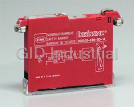


What they say about us
FANTASTIC RESOURCE
One of our top priorities is maintaining our business with precision, and we are constantly looking for affiliates that can help us achieve our goal. With the aid of GID Industrial, our obsolete product management has never been more efficient. They have been a great resource to our company, and have quickly become a go-to supplier on our list!
Bucher Emhart Glass
EXCELLENT SERVICE
With our strict fundamentals and high expectations, we were surprised when we came across GID Industrial and their competitive pricing. When we approached them with our issue, they were incredibly confident in being able to provide us with a seamless solution at the best price for us. GID Industrial quickly understood our needs and provided us with excellent service, as well as fully tested product to ensure what we received would be the right fit for our company.
Fuji
HARD TO FIND A BETTER PROVIDER
Our company provides services to aid in the manufacture of technological products, such as semiconductors and flat panel displays, and often searching for distributors of obsolete product we require can waste time and money. Finding GID Industrial proved to be a great asset to our company, with cost effective solutions and superior knowledge on all of their materials, it’d be hard to find a better provider of obsolete or hard to find products.
Applied Materials
CONSISTENTLY DELIVERS QUALITY SOLUTIONS
Over the years, the equipment used in our company becomes discontinued, but they’re still of great use to us and our customers. Once these products are no longer available through the manufacturer, finding a reliable, quick supplier is a necessity, and luckily for us, GID Industrial has provided the most trustworthy, quality solutions to our obsolete component needs.
Nidec Vamco
TERRIFIC RESOURCE
This company has been a terrific help to us (I work for Trican Well Service) in sourcing the Micron Ram Memory we needed for our Siemens computers. Great service! And great pricing! I know when the product is shipping and when it will arrive, all the way through the ordering process.
Trican Well Service
GO TO SOURCE
When I can't find an obsolete part, I first call GID and they'll come up with my parts every time. Great customer service and follow up as well. Scott emails me from time to time to touch base and see if we're having trouble finding something.....which is often with our 25 yr old equipment.
ConAgra Foods