

 Manufacturers
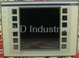
SQUARE D XBTFC064510
Description
Square D XBTFC064510 - Panel PC MAGELiS Operator 10 Color Terminal, XBTFC Pentium Processor-Based Touch ’n Click
Part Number
XBTFC064510
Price
Request Quote
Manufacturer
SQUARE D
Lead Time
Request Quote
Category
PRODUCTS - X
Specifications
Approvals
CE, UL Class 1, Div 2. Group A, B, C, D-T4A, CSA Class 1, Div 2. Group A, B, C, D-T4A
Conforming to Standards
IEC 61131-2, IEC 61000-4-2 level 3, IEC 61000-4-3 and IEC 61000-4-4 level 3, IEC 68-2-6, IEC 68-2-27, UL 508, CSA
Degree of Protection
Front panel: IP 65, conforming to IEC 60529, NEMA Type 4 | Back panel: IP 20, conforming to IEC 60529
Electrical Interference
Conforming to IEC 61000-4-4, level 3
Electromagnetic Interference
Conforming to IEC 61000-4-3, 10 V/m
Electrostatic Discharge
Conforming to IEC 61000-4-2, level 3
LCD Screen
Type: 10.4 in. (264 mm) TFT 256 colors with resistive matrix tactile feedback XBTFC044 has 13 x 8 cells, XBTFC 084 has 13 x 6 cells, XBTFC064 has 9 x 10 cells | Definition: 640 x 480 pixels | Luminescence: 250 cd/m2
Material
Screen protection: 1.8 mm (0.07 in.) thick glass + 0.2 mm (0.008 in.) thick polyester | Front frame: Polyphenyl oxide, 10% glass fibre (PPO GFN1 SE 1) | Keypad: Anti-UV treated toughened polyester (Autoflex EB AG) | Enclosure: Polyphenyl oxide, 10% glass fibre (PPO GFN1 SE 1)
Mounting and Fixing
Flush-mounted, fixed with spring clips (supplied), pressure-mounted on a panel of thickness 0.06–0.24 in. (1.6–6 mm) | 10 spring clips
Optimum View Angle (degrees)
Vertical top: 80 | Vertical bottom: 80 | Vertical right: 80 | Vertical left: 80
Power Supply
Voltage: 24 Vdc not isolated | Limits 18–30 V, including 5% maximum ripple, microbreaks 1 ms maximum | Protection Against polarity inversion and overloads
Relative Humidity
0–85% (without condensation)
Shock Resistance
Conforming to IEC 68-2-27; semi-sinusoidal pulse 11 ms, 15 g in the 3 axes
Temperature
Operation: +32 to +113 °F (0 to +45 °C) | Storage: –4 to +140 °F (–20 to +60 °C)
Touch-Sensitive Keys
12 in two columns
Vibrations
Conforming to IEC 68-2-6; 10–57 Hz at 0.075 mm (0.003 in.); 57–150 Hz 1 g for 3 hours per axis
Features
- Alarm log and managing alarm groups
- Communication protocol application support in the PCMCIA Type II application memory card
- Control via dynamic or static function keys
- Displaying a service line (status and alarm bar) with the current time
- Displaying animated synoptic screens, control, modification of numeric and alphanumeric variables
- Dynamic visualization of operating data (setpoints, measurements, recipes, maintenance messages) and process errors
- Managing help pages, form pages, recipe pages
- Pages called by the user or by the PLC
- Printing form pages, date-stamped log and alarms
- Real-time and trending curves
- Scaling analog variables
- Three levels of passwords
Datasheet

Extracted Text
® MAGELiS Operator Terminals Alphanumeric Matrix Graphic Class 9001 CONTENTS Description Page Product Description . . . . . . . . . . . . . . . . . . . . . . . . . . . . . . . . . . . . . . . . . . . . . . . . . . 3 XBTH/P/E/HM/PM Display Units and Terminals . . . . . . . . . . . . . . . . . . . . . . . . . . . . . 8 XBTH Display Units with 2 Line Alphanumeric Screen. . . . . . . . . . . . . . . . . . . . . . . 10 XBTP Terminals with 2 Line Alphanumeric Screen . . . . . . . . . . . . . . . . . . . . . . . . . 12 XBTE Terminals with 2 or 4 Line Alphanumeric Screen . . . . . . . . . . . . . . . . . . . . . . 14 XBTHM/PM Display Units with 8 Line Matrix Screen . . . . . . . . . . . . . . . . . . . . . . . . 16 XBTF Terminals with Graphic Screen. . . . . . . . . . . . . . . . . . . . . . . . . . . . . . . . . . . . 18 Development Software . . . . . . . . . . . . . . . . . . . . . . . . . . . . . . . . . . . . . . . . . . . . . . . 30 Separate Parts . . . . . . . . . . . . . . . . . . . . . . . . . . . . . . . . . . . . . . . . . . . . . . . . . . . . . 34 XBTF Bus and Network Connections . . . . . . . . . . . . . . . . . . . . . . . . . . . . . . . . . . . . 36 Wiring Diagrams . . . . . . . . . . . . . . . . . . . . . . . . . . . . . . . . . . . . . . . . . . . . . . . . . . . . 39 Schneider Electric Brands Dimensions . . . . . . . . . . . . . . . . . . . . . . . . . . . . . . . . . . . . . . . . . . . . . . . . . . . . . . . . 51 ® MAGELiS Operator Terminals Product Description General The MAGELiS operator terminals come with the following features: Alphanumeric LCD or fluorescent displays 5- or 10-inch size Graphical matrix display Monochrome or color screen Touch sensitive types Configuration software based on the Microsoft Windows programming environment All terminals are programmable using the same software package and the same configuration procedure Graphics terminals use a symbols library that allows the programmer to develop customized, animated screens Many different protocols are supported that allow communication with a wide variety of programmable controllers NOTE: A bullet (•) in the catalog number denotes a character that can vary. 3 © 1999–2001 Schneider Electric All Rights Reserved 5/01 ® MAGELiS Operator Terminals Product Description Display Units with Display Units with Matrix Terminals Terminals with Alphanumeric Screen Alphanumeric Screen Screen Fluorescent green matrix (5 x 7 pixels), height 0.2 in. (5 mm) Fluorescent green matrix Back-lit monochrome matrix LCD Display or (5 x 7 pixels), height 0.2 in. (5 mm) (240 x 64 pixels) Type Back-lit LCD (5 x 7 pixels), height 0.35 in. (9 mm) or height 0.21 or 0.42 in. Back-lit LCD (5 x 7 pixels), height 0.2 in. (5 mm) (5.3 or 10.6 mm) 2 lines of 20 characters 2 or 4 lines of 40 characters 4 to 8 lines of Capacity 20 to 40 characters Display only Via keypad with Via keypad with Display only Data Entry or — 8 function keys — 24 function keys or Via keypad with — 9 service keys — 10 service keys Via keypad with — 4 function keys or — 12 alphanumeric keys — 4 function keys — 1 or 5 service keys — 12 function keys — 1 or 5 service keys — 10 service keys — 12 numeric keys Memory Capacity 128 KB/256 KB Flash EEPROM 256 KB Flash EEPROM 384 KB Flash EEPROM Application Extension via — PCMCIA Type II Functions 100/200 application pages 400 application pages 800 applications pages 600 application pages Maximum Number 128/256 alarm pages 256 alarm pages 256 alarm pages 256 alarm pages of Pages 50 Variables per Page Alphanumeric Alphanumeric, bargraph, gauge Representation of the Variables — Recipes — Curves Dependent on the model Alarm Logs Access to the PLC real-time clock Built-in Access to the PLC real-time clock Real-Time Clock No Yes No Alarm Relay Communication RS 232 C / RS 485 / RS 422 Asynchronous Serial Port ® UNI-TELWAY, MODBUS , AEG Downloadable and for Allen Bradley, GE Fanuc, Omron, Siemens brand PLCs Protocols AS-i with module at 22.5 intervals — AS-i with module at 22.5 intervals Buses and Networks RS 232 C asynchronous serial link (dependent on the model) Printer Port XBTL1000/L1003/L1004 XBTL1003/L1004 Development (under Windows 3.1 or Windows 95) (under Windows 95 and Software Windows NT 4.0) MAGELiS Operating Systems XBTH XBTP XBTE XBTHM Type of Terminal 10 12 14 16 Page 4 © 1999–2001 Schneider Electric All Rights Reserved 5/01 ® MAGELiS Operator Terminals Product Description Display Units with Terminals Terminals with graphic screen matrix screen Display Back-lit monochrome matrix Back-lit monochrome LCD (320 x 240 pixels) Back-lit monochrome LCD (640 x 480 pixels) LCD (240 x 64 pixels) or or Type height 0.21 or 0.42 in. Color LCD STN with touch-sensitive screen (320 x 240 pixels) Back-lit color TFT LCD (640 x 480 pixels) (5.3 or 10.6 mm) Capacity 4 to 8 lines of 5.7 in. (145 mm) 9.5 in. (241 mm) monochrome (XBTF02 only) 20 to 40 characters 10.4 in. (264 mm) color Data Entry Via keypad with Via touch-sensitive screen Via keypad with Via touch-sensitive screen Via keypad with — 12 function keys with — 10 static function keys with — 12 static function keys — 10 service keys 4 touch-sensitive keys — 8 dynamic function keys 8, 12, or 16 touch-sensitive — 10 dynamic function keys (1) — 12 numeric keys (XBTFC) — 12 service keys keys — 12 service keys — 4 dynamic function keys Touch ‘n Click — 12 alphanumeric keys (XBTFC) — 12 alphanumeric keys Touch ‘n Click Memory Capacity Application 5120 KB Flash EEPROM 8 MB Flash EEPROM (using Type II PCMCIA card) Extension via — 8 MB or 16 MB PCMCIA Type II Functions 800 application pages 50 to 720 application, alarm, help, and printout form pages, 30 to 480 application, alarm, help, and printout form pages, 256 alarm pages depending on the memory card used (512 alarms max) depending on the memory card used (512 alarms max) Maximum Number (1) 256 printout form pages of Pages Variables per Page 50 64 Representation Alphanumeric, bargraph, Alphanumeric, bitmap, bargraph, gauge, potentiometer, selector gauge of the Variables Recipes — Maximum 125 records with maximum 5000 values Curves — 16 Alarm Logs Dependent on the model Yes Real-time Clock Access to the PLC real-time clock Alarm Relay No Yes Communication Asynchronous RS 232 C / RS 485 / RS 422 Serial Port Downloadable UNI-TELWAY, MODBUS, AEG and for Allen Bradley, GE Fanuc, Omron, and Siemens brand PLCs Protocols ® ® Buses and Networks AS-i with module MODBUS Plus, FIPIO /FIPWAY with optional Type III PCMCIA card Printer Port RS 232 C asynchronous serial link (dependent on the model) Development XBTL1000/L1003/L1004 XBTL1003/L1004 (under Windows 95 and NT 4.x) Software Operating Systems MAGELiS Type of Terminal XBTPM XBTF01/F03/FC XBTF02/F03/FC Page 17 22, 26 22, 26 (1) Dependent on the model. 5 © 1999–2001 Schneider Electric All Rights Reserved 5/01 ® MAGELiS Operator Terminals Product Description Architectures, connections to control systems MAGELiS operator dialogue terminals communicate with control system equipment: Via serial link Via fieldbus In network architectures Point-to-point or multidrop connection with the PLC via serial link All terminals incorporate an RS 232 C, Quantum RS 422/485 asynchronous serial link as standard. Nano The use of a UNI-TELWAY, MODBUS, or KS protocol means that communication can be set up easily with Schneider Electric PLCs: TSX, MODICON , April, or A-Line. MODBUS Third-party protocols provide connection to PLCs offered by the main market suppliers: XBTHM DF1, DH485 for Allen Bradley PLC5/SLC500 PLCs SNPX for General Electric Series 90 PLCs Sysway for Omron C200 PLCs Micro AS511/3964R, MPI/PPI for Siemens Simatic XBTF S5/S7 PLCs UNI-TELWAY XBTP Connection to PLCs via fieldbus The addition of a Type III PCMCIA communication card to XBTF terminals with graphic screen enables connection to various industrial networks: FIPIO Premium MODBUS Plus XBTF terminals with a graphic screen use the bus TBX master PLC to provide operator dialogue and interactive control of various devices connected on the bus. FIPIO TBX Several terminals with a graphic screen can be Bus connected on the same bus. ATV28 or ATV58 XBTF 6 © 1999–2001 Schneider Electric All Rights Reserved 5/01 ® MAGELiS Operator Terminals Product Description Connection to network architectures The addition of a Type III PCMCIA communication card to XBTF terminals with a graphic screen means that they can be integrated into single or multiple network architectures: FIPWAY network MODBUS Plus network XBTF MODBUS Plus Premium Micro MOMENTUM Quantum XBTF FIPIO Bus ATV28 or ATV58 7 © 1999–2001 Schneider Electric All Rights Reserved 5/01 ® MAGELiS Operator Terminals XBTH/P/E/HM/PM Display Units and Terminals General XBTH/P/E display units and terminals Presentation with alphanumeric screen are used to represent messages and variables. Various keys can be used to modify variables, control the device, or browse in a dialogue application. XBTH XBTHM/PM terminals with matrix screen can also be used to display bitmap XBTP images and animated bar chart and gauge objects. XBTE XBTHM XBTPM Operation All the MAGELiS display units and terminals with alphanumeric and matrix screens have the same user interface: function keys, service keys, and numeric or alphanumeric keys. MAGELiS display units and terminals Configuration can be configured using the same XBTL100 software in a Windows environment. For terminals with an alphanumeric screen, XBTL100 software employs pages. Each page can be viewed in its entirety. Selecting a line of text shows what will appear on the product screen (two to four lines, depending on the model). For XBTHM terminals with a matrix screen, XBTL100 software offers up to 8 lines of 40 characters, and animated bar chart and gauge objects. XBTH/P/E/HM/PM terminals Communication communicate with PLCs via an integrated point-to-point or multidrop serial link. The communication protocols used are those of Schneider PLCs as well as XBTH PLC those of the other main market suppliers. Functions Depending on the model, XBTH/P/E/HM/PM display units and terminals have function keys and service keys on the front panel. Function Keys Function keys are defined for the whole application. They can be used for accessing a page, pulse control, and toggle set/reset. Service Keys Service keys are the arrow keys and the control keys combined. Service keys are used to modify the parameters of the control system. 8 © 1999–2001 Schneider Electric All Rights Reserved 5/01 ® MAGELiS Operator Terminals XBTH/P/E/HM/PM Display Units and Terminals The control keys are used to perform the following actions: ENTER Confirm a selection or entry, acknowledge an alarm MOD Change to the mode for entering pages, passwords, fields, or graphic objects ESC Cancel an entry, suspend or stop a current action SHIFT Access the second of the dual key functions MENU Access a menu containing the operating functions HOME Return to the entry point of the current menu Example: return to the first page of the application SYST Access the confidential mode, which contains the implementation functions ALARM View the alarms PRINT Print The arrow keys are used to: Change page within a menu Move within a page Select the value of a digit Select a value from a list of choices When used with the SHIFT key, increment or decrement the value of a variable field Description XBTH/P/E/HM/PM display units and terminals include: On the front panel: 1. A communication monitoring indicator lamp 1 3 2. A keypad activity indicator lamp (dependent on the model) 2 3. Fluorescent or LCD back-lit display 6 4. Function keys with indicator lamp and reusable labels 4 5. Service keys with indicator lamp 5 6. Twelve numeric keys (for XBTP02) Twelve alphanumeric keys [0 to 9, (+/–), (.)] associated with three alphabetical access keys (A to Z) for XBTE On the rear: 1. A plug-in terminal block for 24 Vdc power supply and a connection for the alarm relay (dependent on the model) 2. A female 25-pin SUB-D connector for connection to PLCs, FTX configuration terminals, or PC compatibles 3. A male 9-pin SUB-D connector for the printer connection (dependent on the model) 12 3 9 © 1999–2001 Schneider Electric All Rights Reserved 5/01 ® MAGELiS Operator Terminals XBTH Display Units with 2 Line Alphanumeric Screen Selection Display Units with 2 Lines of 20 Characters (Fluorescent) Number of Keys Downloadable Supply Voltage Language Catalog Weight Alpha- Exchange Protocol (VDC) Version Number lbs (kg) Function Service numeric No Printer Port, No Log —— — 24 Multilingual XBTH002010 1.3 (0.6) See page 34 41 — 24 Multilingual XBTH022010 1.3 (0.6) — 5 — 24 Multilingual XBTH012010 1.3 (0.6) With Printer Port and Log XBTH02010 See page 34 — 5 — 24 Multilingual XBTH012110 1.3 (0.6) Display Units with 2 Lines of 20 Characters (LCD) Number of Keys Downloadable Supply Voltage Language Catalog Weight Alpha- Exchange Protocol (VDC) Version Number lbs (kg) Function Service numeric No Printer Port, No Log 24 and 5 via terminal UNI-TELWAY — 5 — socket on the TSX Multilingual XBTH811050 1.3 (0.6) See page 34 Nano/Micro/Premium PLC XBTH0110 Display Units with 2 Lines of 20 Characters (Back-Lit LCD) Number of Keys Downloadable Supply Voltage Language Catalog Weight Alpha- Exchange Protocol (VDC) Version Number lbs (kg) Function Service numeric No Printer Port, No Log —— — 24 Multilingual XBTH001010 1.3 (0.6) See page 34 41 — 24 Multilingual XBTH021010 1.3 (0.6) — 5 — 24 Multilingual XBTH011010 1.3 (0.6) XBTH00010 Separate Parts Catalog Weight Description Use Number lbs (kg) Development Software Under Windows 3.1 or 95, for downloading the application and protocols See page 33 — Connecting Cables Connection to PLCs, configuration terminals, etc. See page 34 — Documentation Catalog Weight Description Format Included in the Product Number � lbs (kg) MAGELiS A5 Bound XBTL1003 and XBTL1004 XBTX000 0.4 (0.2) User’s Manual (148 x 210 mm, approx. 6 x 8.25 in) � Add the following suffixes EN: English, FR: French, DE: German, ES: Spanish, 1T: Italian. 10 © 1999–2001 Schneider Electric All Rights Reserved 5/01 ® MAGELiS Operator Terminals XBTH Display Units with 2 Line Alphanumeric Screen Specifications Type of Display Unit XBTH0210 (Fluorescent) XBTH811050 (LCD) XBTH01010 (Back-Lit LCD) Environment Conforming to Standards IEC 61131-2, IEC 60068-2-6, IEC 60068-2-27, EN 61131-2, UL 508, CSA C22-2 No. 142 CE, UL, CSA, UL E164866, CCN: NRAQ, CSA LR 44087, Class 2252 01 Product Certifications Operation +32 to +122 °F (0 to +50 °C) Temperature Storage –40 to +158 °F (–40 to +70 °C) –4 to +140 °F (–20 to +60 °C) Degree of Protection IP 65, conforming to IEC 60529, NEMA Type 4, UL Type 4 Mechanical Characteristics Flush-mounted, fixed with 4 or 6 screws (supplied), pressure-mounted on a panel of thickness 0.04–0.24 in. (1–6 mm) Mounting and Fixing Enclosure Polyphenyl oxide, 10% glass fiber (PPO GFN1 SE1) Material Keypad Anti-UV treated toughened polyester (Autoflex EB AG) XBTH002 XBTH022 XBTH012 XBTH001 XBTH021 XBTH011 XBTH811050 010 010 10 010 010 010 No keys 4 function 5 service 5 service keys No key 4 function 5 service Keys keys keys keys keys 1 service 1 service key key Electrical Characteristics Fluorescent green matrix characters LCD Back-lit LCD Display Unit (5 x 7 pixels) (5 x 7 pixels) (5 x 7 pixels) 2 lines of 20 characters, 2 lines of 20 characters, 2 lines of 20 characters, height 0.2 in. (5 mm) height 0.35 in. (9 mm) height 0.35 in. (9 mm) Voltage 24 Vdc not isolated During configuration: 24 Vdc not isolated Power 24 Vdc not isolated Supply During operation: 5 Vdc via TSX Nano/Micro/Premium PLC terminal port Voltage Limits 18–30 V Ripple 5% maximum Consumption 10 W 1.5 W 10 W Operating Characteristics XBTH002 XBTH022 XBTH012 XBTH001 XBTH021 XBTH011 XBTH81150 010 010 10 010 010 010 Signaling 1 LED 6 LEDs 4 LEDs — 1 LED 6 LEDs 4 LEDs 128 KB Flash EEPROM, 128 KB Flash EEPROM 128 KB Flash EEPROM, Memory 256 KB (XBTH012110) 100 application pages approximately 256 KB (XBTH011010) 200 application pages approximately (2 lines per page) 200 application pages approximately (2 lines per page) 128 available alarm pages (2 lines per page) 256 available alarm pages (2 lines per page) 256 available alarm pages (2 lines per page) (2 lines per page) Permits storage of alarm pages Log Function —— (XBTH012110) Transmission RS 232 C / RS 285 / RS 422 RS 232 C / RS 485 RS 232 C / RS 485 / RS 422 (asynchronous serial link) Downloadable Protocol Multiple (see pages 8 and 34) UNI-TELWAY (see pages 8 and 34) Multiple (see page 8 and 34) Access to the PLC real-time clock Real-Time Clock Printer Port RS 232 C (XBTH012110) —— (asynchronous serial link) Power Supply Plug-in terminal block Connection 3 screw terminals, 13/64” (5.08 mm) pitch 2 Maximum clamping capacity: #16 AWG (1.5 mm ), 0.5–0.6 Nm Serial Port Female 25-pin SUB-D connector —— Printer Port Male 9-pin SUB-D connector —— 11 © 1999–2001 Schneider Electric All Rights Reserved 5/01 ® MAGELiS Operator Terminals XBTP Terminals with 2 Line Alphanumeric Screen Selection Terminals with 2 Lines of 20 Characters (Fluorescent) Number of Keys Downloadable Supply Voltage Language Catalog Weight Alpha- Exchange Protocol (VDC) Version Number lbs (kg) Function Service numeric No Printer Port, No Log 89 — 24 Multilingual XBTP012010 1.8 (0.8) See page 34 12 10 12 24 Multilingual XBTP022010 1.8 (0.8) With Printer Port and Log See page 34 12 10 12 24 Multilingual XBTP022110 1.8 (0.8) XBTP01010 Terminals with 2 Lines of 20 Characters (Back-Lit LCD) Number of Keys Downloadable Supply Voltage Language Catalog Weight Alpha- Exchange Protocol (VDC) Version Number lbs (kg) Function Service numeric No Printer Port, No Log 89 — 24 Multilingual XBTP011010 1.8 (0.8) See page 34 12 10 12 24 Multilingual XBTP021010 1.8 (0.8) With Printer Port and Log See page 34 12 10 12 24 Multilingual XBTP021110 1.8 (0.8) XBTP0210 Separate Parts Catalog Weight Description Use Number lbs (kg) Development Software Under Windows 3.1 or 95, for downloading the application and protocols See page 33 — Connecting Cables Connection to PLCs, configuration terminals, etc. See page 34 — Documentation Catalog Weight Description Format Included in the Product Number � lbs (kg) MAGELiS A5 Bound XBTL1003 and XBTL1004 XBTX000 0.4 (0.2) User’s Manual (148 x 210 mm, approx. 6 x 8.25 in) � Add the following suffixes EN: English, FR: French, DE: German, ES: Spanish, 1T: Italian. 12 © 1999–2001 Schneider Electric All Rights Reserved 5/01 ® MAGELiS Operator Terminals XBTP Terminals with 2 Line Alphanumeric Screen Specifications Type of Terminal XBTP0210 (Fluorescent) XBTP0110 (Back-Lit LCD) Environment Conforming to Standards IEC 61131-2, IEC 60068-2-6, IEC 60068-2-27, EN 61131-2, UL 508, CSA C22-2 No. 142 CE, UL, CSA, UL E164866, CCN: NRAQ, CSA LR 44087, Class 2252 01 Product Certifications Operation +32 to +122 °F (0 to +50 °C) Temperature Storage –40 to +158 °F (–40 to +70 °C) –4 to +140 °F (–20 to +60 °C) Degree of Protection IP 65, conforming to IEC 60529, NEMA Type 4, UL Type 4 Mechanical Characteristics Flush-mounted, fixed with 4 or 6 screws (supplied), pressure-mounted on a panel of thickness 0.04–0.24 in. (1–6 mm) Mounting and Fixing Enclosure Polyphenyl oxide, 10% glass fiber (PPO GFN1 SE1) Material Keypad Anti-UV treated toughened polyester (Autoflex EB AG) XBTP012010 XBTP02210 XBTP011010 XBTP02110 8 function keys 12 function keys 8 function keys 12 function keys Keys 9 service keys 10 service keys 9 service keys 10 service keys 12 numeric keys 12 numeric keys Electrical Characteristics Fluorescent green matrix characters (5 x 7 pixels) Back-lit LCD (5 x 7 pixels) Display Unit 2 lines of 20 characters, height 0.20 in. (5 mm) 2 lines of 20 characters, height 0.35 in. (9 mm) Voltage 24 Vdc not isolated Power Supply Voltage Limits 18–30 V Ripple 5% maximum 10 W Consumption Operating Characteristics XBTP012010 XBTP02210 XBTP011010 XBTP02110 Signaling 17 LEDs 21 LEDs 17 LEDs 21 LEDs 256 KB Flash EEPROM Memory 400 application pages approximately (2 lines per page) 256 available alarm pages (2 lines per page) Log Function Permits storage of alarm pages (XBTP022110) Permits storage of alarm pages (XBTP021110) Transmission RS 232 C / RS 485 / RS 422 (asynchronous serial link) Multiple (see pages 8 and 34) Downloadable Protocol Real-Time Clock Access to the PLC real-time clock Printer Port RS 232 C (XBTP022110) RS 232 C (XBTP021110) (asynchronous serial link) Power Supply Plug-in terminal block Connection 3 screw terminals, 13/64” (5.08 mm) pitch 2 Maximum clamping capacity: #16 AWG (1.5 mm ), 0.5–0.6 Nm Serial Port Female 25-pin SUB-D connector Printer Port Male 9-pin SUB-D connector 13 © 1999–2001 Schneider Electric All Rights Reserved 5/01 ® MAGELiS Operator Terminals XBTE Terminals with 2 or 4 Line Alphanumeric Screen Selection Terminals with 2 Lines of 40 Characters (Fluorescent) Number of Keys Downloadable Supply Voltage Language Catalog Weight Alpha- Exchange Protocol (VDC) Version Number lbs (kg) Function Service numeric No Printer Port, No Log See page 34 24 10 12 24 Multilingual XBTE014010 2.2 (1.0) With Printer Port and Log See page 34 24 10 12 24 Multilingual XBTE014110 2.2 (1.0) XBTE01410 Terminals with 4 Lines of 40 Characters (Fluorescent) Number of Keys Downloadable Supply Voltage Language Catalog Weight Alpha- Exchange Protocol (VDC) Version Number lbs (kg) Function Service numeric No Printer Port, No Log See page 34 24 10 12 24 Multilingual XBTE016010 2.2 (1.0) With Printer Port and Log See page 34 24 10 12 24 Multilingual XBTE016110 2.2 (1.0) XBTE01610 Terminals with 2 Lines of 40 Characters (Back-Lit LCD) Number of Keys Downloadable Supply Voltage Language Catalog Weight Alpha- Exchange Protocol (VDC) Version Number lbs (kg) Function Service numeric No Printer Port, No Log See page 34 24 10 12 24 Multilingual XBTE013010 2.2 (1.0) With Printer Port and Log See page 34 24 10 12 24 Multilingual XBTE013110 2.2 (1.0) XBTE01310 Terminals with 4 Lines of 40 Characters (Back-Lit LCD) Number of Keys Downloadable Supply Voltage Language Catalog Weight Alpha- Exchange Protocol (VDC) Version Number lbs (kg) Function Service numeric No Printer Port, No Log See page 34 24 10 12 24 Multilingual XBTE015010 2.2 (1.0) With Printer Port and Log See page 34 24 10 12 24 Multilingual XBTE015110 2.2 (1.0) XBTE01510 Separate Parts Catalog Weight Description Use Number lbs (kg) Development Software Under Windows 3.1 or 95, for downloading the application and protocols See page 33 — Connecting Cables Connection to PLCs, configuration terminals, etc. See page 34 — Documentation Catalog Weight Description Format Included in Product Number � lbs (kg) MAGELiS A5 Bound XBTL1003 and XBTL1004 XBTX000 0.4 (0.2) User’s Manual (148 x 210 mm, approx. 6 x 8.25 in) � Add the following suffixes EN: English, FR: French, DE: German, ES: Spanish, 1T: Italian. 14 © 1999–2001 Schneider Electric All Rights Reserved 5/01 ® MAGELiS Operator Terminals XBTE Terminals with 2 or 4 Line Alphanumeric Screen Specifications Type of Terminal XBTE01410/XBTE01610 (Fluorescent) XBTE01310/XBTE01510 (Back-Lit LCD) Environment Conforming to Standards IEC 61131-2, IEC 60068-2-6, IEC 60068-2-27, EN 61131-2, UL 508, CSA C22-2 No. 142 CE, UL, CSA, UL E164866, CCN: NRAQ, CSA LR 44087, Class 2252 01 Product Certifications Operation +32 to +122 °F (0 to +50 °C) Temperature Storage –40 to +158 °F (–40 to +70 °C) –4 to +140 °F (–20 to +60 °C) Degree of Protection IP 65, conforming to IEC 60529, NEMA Type 4, UL Type 4 Mechanical Characteristics Flush-mounted, fixed with 4 or 6 screws (supplied), pressure-mounted on a panel of thickness 0.04–0.24 in. (1–6 mm) Mounting and Fixing Enclosure Polyphenyl oxide, 10% glass fiber (PPO GFN1 SE1) Material Keypad Anti-UV treated toughened polyester (Autoflex EB AG) Function 24 Keys Service 10 Alphanumeric 12 Electrical Characteristics Fluorescent green matrix characters (5 x 7 pixels) Back-lit LCD (5 x 7 pixels) Display Unit XBTE01410 XBTE01610 XBTE01310 XBTE01510 2 lines of 40 characters, 4 lines of 40 characters, 2 lines of 40 characters, 4 lines of 40 characters, height 0.20 in. (5 mm) height 0.20 in. (5 mm) height 0.20 in. (5 mm) height 0.20 in. (5 mm) Voltage 24 Vdc not isolated Power Supply Voltage Limits 18–30 V Ripple 5% maximum 20 W 10 W Consumption Operating Characteristics Signaling 33 LEDs + 1 buzzer 384 KB Flash EEPROM Memory 800 application pages approximately (2 lines per page) 256 available alarm pages (2 lines per page) 400 application pages approximately (4 lines per page) 128 available alarm pages (4 lines per page) Log Function Permits storage of alarm pages Transmission RS 232 C / RS 485 / RS 422 (asynchronous serial link) Multiple (see pages 8 and 34) Downloadable Protocol Real-Time Clock Access to the PLC real-time clock Printer Port RS 232 C (XBTE014110 and XBTE016110) RS 232 C (XBTE013110 and XBTE015110) (asynchronous serial link) 1 N.O. contact Alarm Relay min. 1 mA/5 Vdc max. 0.5 A/24 Vdc Power Supply Plug-in terminal block Connection and Alarm 3 screw terminals, 13/64” (5.08 mm) pitch 2 Relay Maximum clamping capacity: #16 AWG (1.5 mm ), 0.5–0.6 Nm Serial Port Female 25-pin SUB-D connector Printer Port Male 9-pin SUB-D connector 15 © 1999–2001 Schneider Electric All Rights Reserved 5/01 ® MAGELiS Operator Terminals XBTHM/PM Display Units with 8 Line Matrix Screen Selection Display Units with 8 Line Matrix Screen of 40 Characters (Back-Lit LCD) Number of Keys Downloadable Supply Voltage Language Catalog Weight Exchange Protocol Alpha- (VDC) Version Number lbs (kg) Function Service See page 34 numeric ——— 24 Multilingual XBTHM007010 1.3 (0.6) No Printer Port, No Log 41 — 24 Multilingual XBTHM027010 1.3 (0.6) — 5 — 24 Multilingual XBTHM017010 1.3 (0.6) XBTHM007010 PowerSuite� — 5 — 24 Multilingual XBTHM017010A8 1.3 (0.6) With Printer Port and Log — 5 — 24 Multilingual XBTHM017110 1.3 (0.6) � Terminal specifically for controlling up to eight ATV28/ATV58 variable-speed drive controllers. Separate Parts Catalog Weight Description Use Number lbs (kg) Development Software Under Windows 95 or NT 4.0, for downloading the application and protocols See page 33 — Connecting Cables Connection to PLCs, configuration terminals, etc. See page 34 — Documentation XBTHM027010 Catalog Weight Description Format Included in Product Number � lbs (kg) MAGELiS User’s Manual A5 Bound (148 x 210 mm, approx. 6 x 8.25 in) XBTL1003 and XBTL1004 XBTX000 0.4 (0.2) � Add the following suffixes EN: English, FR: French, DE: German, ES: Spanish, 1T: Italian. Specifications Type of Display Unit XBTHM0710 (Back-Lit LCD) Environment Conforming to Standards IEC 61131-2, IEC 60068-2-6, IEC 60068-2-27, EN 61131-2, UL 508, CSA C22-2 No. 142 Product Certifications CE, UL, CSA, UL E164866, CCN: NRAQ, CSA LR 44087, Class 2252 01 XBTHM01710 Operation +32 to +122 °F (0 to +50 °C) Temperature Storage –4 to +140 °F (–20 to +60 °C) Degree of Protection IP 65, conforming to IEC 60529, NEMA Type 4, UL Type 4 Mechanical Characteristics Flush-mounted, fixed with spring clips (supplied), Mounting and Fixing pressure-mounted on a panel of thickness 0.04–0.24 in. (1–6 mm) Enclosure Polyphenyl oxide, 10% glass fiber (PPO GFN1 SE1) Material Keypad Anti-UV treated toughened polyester (Autoflex EB AG) XBTHM007010 XBTHM027010 XBTHM01710 Keys No keys 4 function keys + 1 service key 5 service keys Electrical Characteristics Back-lit LCD (240 x 64 pixels) Display Unit 8 lines of 40 character, height 0.21 in. (5.3 mm), single size 4 lines of 20 characters height 0.42 in. (10.6 mm), double height, double width Voltage 24 Vdc not isolated Power Supply Voltage Limits 18–30 V Ripple 5% maximum Consumption 15 W Operating Characteristics XBTHM007010 XBTHM027010 XBTHM01710 Signaling 1 LED 6 LEDs 4 LEDs 384 KB Flash EEPROM Memory 600 application pages approximately (8 lines per page), 256 available alarm pages (2 lines per page) Transmission (asynchronous serial link) RS 232 C / RS 485 / RS 422 Downloadable Protocol Multiple (see pages 8 and 34) Access to the PLC real-time clock Real-Time Clock Printer Port (asynchronous serial link) RS 232 C (XBTHM017110) Power Supply Plug-in terminal block Connection 3 screw terminals, 13/64” (5.08 mm) pitch 2 Maximum clamping capacity: #16 AWG (1.5 mm ), 0.5–0.6 Nm Serial Port Female 25-pin SUB-D connector Printer Port Male 9-pin SUB-D connector 16 © 1999–2001 Schneider Electric All Rights Reserved 5/01 ® MAGELiS Operator Terminals XBTHM/PM Display Units with 8 Line Matrix Screen Selection Terminals with 8 Line Matrix Screen of 40 Characters (Back-Lit LCD) Number of Keys Supply Downloadable Language Weight Voltage Catalog Number Dynamic Alpha- Exchange Protocol Version lbs (kg) Function Service (VDC) Function numeric No Printer Port XBTPM 12 4 10 12 24 Multilingual XBTPM027010 1.32 (0.6) See page 34 With Printer Port 12 4 10 12 24 Multilingual XBTPM027110 1.32 (0.6) See page 34 Separate Parts Weight Description Use Catalog Number lbs (kg) Development Software Under Windows 95 or NT 4.0, for downloading the application and protocols See page 33 — Connecting Cables Connection to PLCs, configuration terminals, etc. See page 34 — Documentation Weight Description Format Included in the Product Catalog Number � lbs (kg) A5 Bound MAGELiS ® User's Manual XBTL1003 and XBTL1004 XBTX000 0.4 (0.2) (148 x 210 mm, approx. 6 x 8.25 in) � Add the following suffixes EN: English, FR: French, DE: German, ES: Spanish, 1T: Italian. Specifications Type of Display Unit XBTPM02710 (Back-Lit Matrix LCD) Environment IEC 61131-2, IEC 60068-2-6, IEC 60068-2-27, EN 61131-2, UL 508, CSA C22-2 No. 142 Conforming to Standards CE, UL, CSA, UL E164866, CCN: NRAQ, CSA LR 44087, Class 2252 01, UL Class 1, Division 2, Product Certifications groups ABCD T5 Operation +32 to +122 °F (0 to +50 °C) Temperature Storage –4 to +140 °F (–20 to +60 °C) IP 65, conforming to IEC 60529, NEMA Type 4, UL Type 4 Degree of Protection Mechanical Characteristics Flush-mounted, fixed with spring clips (supplied), Mounting and Fixing pressure-mounted on a panel of thickness 0.06–0.24 in. (1.6–6 mm) Enclosure Polyphenyl oxide, 10% glass fiber (PPO GFN1 SE1) Material Keypad Anti-UV treated toughened polyester (Autoflex EB AG) Function 12 static, 4 dynamic Keys Service 12 Numeric 12 Electrical Characteristics Back-lit LCD (240 x 64 pixels) Display Unit 8 lines of 40 characters, height 0.21 in. (5.3 mm), single size 4 lines of 20 characters, height 0.42 in. (10.6 mm), double height, double width Voltage 24 Vdc, not isolated Power Supply Voltage Limits 18–30 V Ripple 5% maximum Consumption 15 W Operating Characteristics Signaling 25 LEDs 256 KB Flash EEPROM Memory 400 application pages approximately 256 available alarm pages depending on distribution Transmission (asynchronous serial link) RS 232 C / RS 485 / RS 422 Multiple (see pages 8 and 34) Downloadable Protocol Real-Time Clock Access to the PLC real-time clock Printer Port (asynchronous serial link) RS 232 C (XBTPM027110) Power Supply Plug-in terminal block Connection 3 screw terminals 13/64” (5.08 mm) pitch 2 Maximum clamping capacity: #16 AWG (1.5 mm ), 0.5–0.6 Nm Serial Port 25-pin SUB-D connector Printer Port 9-pin SUB-D connector 17 © 1999–2001 Schneider Electric All Rights Reserved 5/01 ® MAGELiS Operator Terminals XBTF Terminals with Graphic Screen General Graphic screen operator dialogue terminals are Presentation available with 5 or 10 in. (127 or 254 mm) screens, in monochrome or color, with a keypad or a touch- sensitive screen. XBTF graphic screen terminals are specially designed for operator dialogue graphic functions. XBTF01/F03 XBTF02/F03 XBTFC02/F04 XBTFC06/F08 All MAGELiS graphic screen terminals have the Operation same user interface: static and dynamic function keys, service keys, alphanumeric keys. Configuration MAGELiS graphic screen terminals can be configured using the same XBTL100 software in a Windows environment. XBTL100 software provides graphic screen terminals with a library of animated graphic objects such as bargraphs, volume indicator meters, selectors, potentiometers, and trending curves. The variable for animating an object can be selected directly from a list of symbols given by the TM PL7 or CONCEPT software. The application program for the graphic terminals is stored on a PCMCIA memory card. Communication XBTF graphic screen terminals communicate with XBTF PLCs via an integrated point-to-point or multidrop PLC serial link, or via a field bus with a PCMCIA Type III card. The communication protocols are those used by Schneider Electric PLCs as well as those of the other main market suppliers. PLC 18 © 1999–2001 Schneider Electric All Rights Reserved 5/01 ® MAGELiS Operator Terminals XBTF Terminals with Graphic Screen Functions XBTF graphic screen operator dialogue terminals have the following functions: Displaying animated synoptic screens, control, modification of numeric and alphanumeric variables Displaying a service line (status and alarm bar) with the current time Dynamic visualization of operating data (setpoints, measurements, recipes, maintenance messages) and process errors Control via dynamic or static function keys Scaling analog variables Real-time and trending curves Alarm log and managing alarm groups Managing help pages, form pages, recipe pages Pages called by the user or by the PLC Three levels of passwords Printing form pages, date-stamped log and alarms Communication protocol application support in the PCMCIA Type II application memory card The role of the function keys is defined using the XBTL100 software. Modifications cannot be made during operation. Each function key can be associated with an internal bit of the PLC application. Static Function Keys (F) Static function keys are defined for the whole application. They perform the following actions: Accessing a page Pulse control Toggle set/reset control Static keys can be marked with reusable labels. Dynamic function keys and touch-sensitive keys Dynamic function keys and touch-sensitive keys are associated with a page. Their role can therefore differ from one page to another. They perform the following actions: Accessing a page Latching memory bits Toggling memory bits (on/off) Accessing the modification of a value Direct writing Each dynamic key and touch-sensitive key can be assigned a label or icon illustrating its function. On touch-sensitive terminals, the touch-sensitive zones function in a similar way to the dynamic keys on keypad terminals. 19 © 1999–2001 Schneider Electric All Rights Reserved 5/01 ® MAGELiS Operator Terminals XBTF Terminals with Graphic Screen Service Keys Service keys are the arrow keys and the control keys combined. Service keys are used to modify the parameters of the control system. The control keys perform the following actions: ENTER Confirm a selection or entry, acknowledge an alarm MOD Change to the mode for entering pages, passwords, fields, or graphic objects ESC Cancel an entry, suspend or stop a current action; display previous pages in succession; quit the alarm display SHIFT Access the second of the dual key functions MENU Access a menu containing the operating functions that do not have direct access keys HOME Return to the entry point of the current menu Example: return to the first page of the application SYST Access the confidential mode that contains the password- protected implementation functions ALARM View the alarms PRINT Print The arrow keys perform the following actions: Change the page within a menu Change fields on a page Select an object on a page Move within a page Select the value of a digit Select a value from a list of choices When used with the SHIFT key, increment or decrement the value of a variable field 20 © 1999–2001 Schneider Electric All Rights Reserved 5/01 ® MAGELiS Operator Terminals XBTF Terminals with Graphic Screen XBTF01/F02 Description The front panel of XBTF01/F02 keypad terminals includes: 1. A monochrome or color screen 5.7, 9.5, or 10.4 in. (145, 241, or 264 mm) 3 1 depending on the model 2. 2 x 4 or 2 x 5 dynamic function keys (depending on the model) with indicator lights 2 2 3. A communication monitoring indicator light 4. A keypad activity indicator light 5. 2 x 5 or 2 x 6 static function keys (depending on the model) 4 with indicator lights and re-usable labels 6. Twelve service keys with indicator lights 7. Twelve alphanumeric keys [0 to 9, (+/–), (.)] 5 5 associated with three alphabetical access keys (A to Z) 6 7 The front panel of XBTF03 touch-sensitive screen terminals includes: 1. A touch-sensitive color screen 2 5.7 or 10.4 in. (145 or 264 mm) depending on the model 3 2. A communication monitoring indicator light 3. A tactile feedback activity indicator light 1 The front panel of XBTFC touch-sensitive screen terminals includes: 1. A touch-sensitive color screen 5.7 or 10.4 in. (145 or 264 mm) 2 depending on the model 3 2. A communication monitoring indicator light 4 1 3. A tactile feedback activity indicator light 4. An alarm indicator light 5. 4, 8, 12, or 16 touch-sensitive keys (depending on the Touch ‘n Click model) 5 21 © 1999–2001 Schneider Electric All Rights Reserved 5/01 ® MAGELiS Operator Terminals XBTF Terminals with Graphic Screen Selection Terminals with Keypads Downloadable Supply Voltage Type III Slot for PCMCIA Catalog Weight Type and Size of Screen Exchange Protocol (VDC) Communication Card Number lbs (kg) No XBTF011110 4.0 (1.8) Monochrome 24 5.7 in. (145 mm) Yes XBTF011310 4.0 (1.8) No XBTF023110 6.0 (2.7) Monochrome See page 34 24 9.5 in. (241 mm) Yes XBTF023310 6.0 (2.7) No XBTF024110 6.0 (2.7) Color 24 10.4 in. (264 mm) Yes XBTF024310 6.0 (2.7) XBTF02410 Terminals with Touch-Sensitive Screens Downloadable Supply Voltage Type III Slot for PCMCIA Catalog Weight Type and Size of Screen Exchange Protocol (VDC) Communication Card Number lbs (kg) No XBTF032110 3.5 (1.6) Color 24 5.7 in. (145 mm) Yes XBTF032310 3.5 (1.6) See page 34 No XBTF034110 5.3 (2.4) Color 24 10.4 in. (264 mm) Yes XBTF034310 5.3 (2.4) XBTF03410 Separate Parts Catalog Weight Description Use Number lbs (kg) Development Software Under Windows 95 or NT 4.0, for downloading the application and protocols See page 33 — PCMCIA Type II Application memory See page 34 — Memory Cards PCMCIA Type III Bus and industrial networks connection See page 34 — Memory Cards Connecting Cables Connection to PLCs, configuration terminals, etc. See page 34 — Sheet of Labels Labels for function keys See page 34 — Replacement Parts Catalog Weight Description Use Memory Number lbs (kg) PCMCIA Type II XBTF terminals 8 MB XBTMEM08 0.2 (0.1) Memory Card PCMCIA Type II XBTF terminals 16 MB XBTMEM16 0.2 (0.1) Memory Card XBTMEM08 22 © 1999–2001 Schneider Electric All Rights Reserved 5/01 ® MAGELiS Operator Terminals XBTF Terminals with Graphic Screen Specifications Type of Terminal XBTF011 XBTF032 XBTF023/F024 XBTF034 Environment IEC 61131-2, IEC 60801-2 level 3, IEC 60801-3 and IEC 60801-4 level 3, IEC 60068-2-6, IEC 60068-2-27, UL 508, Conforming to Standards CSA C22.2 No. 142 CE, UL Class 1, Div 2. Group A, B, C, D-T4A, CSA Class 1, Div 2. Group A, B, C, D-T4A Product Certifications Operation +32 to +113 °F (0 to +45 °C) Temperature Storage –4 to +140 °F (–20 to +60 °C) Front Panel IP 65, conforming to IEC 60529, NEMA Type 4, UL Type 4 Degree of Protection Rear Panel IP 20, conforming to IEC 60529 Mechanical Characteristics Flush-mounted, fixed with spring clips (supplied), Mounting and Fixing pressure-mounted on a panel of thickness 0.06–0.24 in. (1.6–6 mm) 10 spring clips 8 spring clips 12 spring clips 10 spring clips Front Section Polyphenyl oxide, 10% glass fiber (PPO GFN1 SE1) Material Keypad Anti-UV treated toughened polyester (Autoflex EB AG) Enclosure Polyphenyl oxide, 10% glass fiber (PPO GFN1 SE1) Dynamic Keys 8 (with LED) — 10 (with LED) — Keys 10 (with LED and — 12 (with LED and — Static Keys re-usable labels) re-usable labels) Service Keys 12 — 12 — Alphanumeric 12, plus 3 for alphabetical — 12, plus 3 for alphabetical — Keys access access Electrical Characteristics Type 5.7 in. (145 mm) 5.7 in. (145 mm) STN XBTF023: 9.5 in. (241 mm) 10.4 in. (264 mm) TFT LED Screen monochrome, back-lit with 256 colors, back-lit with monochrome, back-lit with 256 colors with resistive 16 levels of grey resistive matrix tactile 16 levels of grey matrix tactile feedback feedback XBTF024: 10.4 in. (264 mm) TFT 256 colors Resolution 320 x 240 pixels 640 x 480 pixels Voltage 24 Vdc not isolated Power Supply Voltage Limits 18–30 V, maximum ripple 5%, maximum microbreaks 1 ms Protection Against polarity inversion and overloads Consumption 35 W Operating Characteristics 1 LED for communication monitoring, 1 LED for keypad activity (or tactile feedback activity), and 11 LEDs Signaling associated with service and alphanumeric keys Operating System MAGELiS Dynamic RAM Memory 2.5 MB On 8 MB PCMCIA Type II card (supplied), 8, 16 MB Application Memory Max. number 50–450 application, alarm, help, form, and recipe pages 30–300 application, alarm, help, form, and recipe pages Dialogue of pages depending on the memory card used depending on the memory card used Application Curves 16 real-time curves 16 real-time curves Real-Time Clock Access to the PLC real-time clock One volt-free N.O. contact, max. 0.5 A, 24 Vdc/Vac Alarm Relay Power Supply Connection Plug-in terminal, 5 screw terminals, 13/64” (5.08 mm) pitch and 2 Maximum clamping capacity: #16 AWG (1.5 mm ), 0.5–0.6 Nm Alarm Relay PLC Female 25-pin SUB-D connector Printer/Config Male 9-pin SUB-D connector uration PC 23 © 1999–2001 Schneider Electric All Rights Reserved 5/01 ® MAGELiS Operator Terminals Pentium Processor Terminal with Graphic Screen Selection Terminals with Keypads and pentium processor Downloadable Supply Voltage RJ 45 Ethernet 10/100 Catalog Weight Type and Size of Screen Exchange Protocol (VDC) TCP/IP Connector Number lbs (kg) No XBTF024510 6.0 (2.7) Color See page 34 24 10.4 in. (264 mm) Yes XBTF024610 6.0 (2.7) Terminals with Touch-Sensitive Screens and pentium processor Downloadable Supply Voltage RJ 45 Ethernet 10/100 Catalog Weight Type and Size of Screen Exchange Protocol (VDC) TCP/IP Connector Number lbs (kg) XBTF02410 No XBTF034510 5.3 (2.4) Color See page 34 24 10.4 in. (264 mm) Yes XBTF034610 5.3 (2.4) Specifications Type of Terminal XBTF024 XBTF034 Environment IEC 61131-2, IEC 61000-4-2 level 3, IEC 61000-4-3 and IEC 61000-4-4 level 3, IEC 60068-2-6, IEC 60068-2-27, Conforming to Standards XBTF03410 UL 508, CSA Product Certifications CE, UL Class 1, Div 2. Group A, B, C, D-T4A, CSA Class 1, Div 2. Group A, B, C, D-T4A Operation +32 to +113 °F (0 to +45 °C) Temperature Storage –4 to +140 °F (–20 to +60 °C) 0 t0 85 % (without condensation) Relative Humidity Front Panel IP 65, conforming to IEC 60529, NEMA Type 4 Degree of Protection Rear Panel IP 20, conforming to IEC 60529 Shock Resistance Conforming to IEC 60068-2-27; semi-sinusoidal pulse 11 ms, 15 gn in the 3 axes Vibrations Conforming to IEC 60068-2-6; 10 to 57 Hz at 0.075 mm; 57 to 150 Hz 1 g for 3 hours per axis Conforming to IEC 61000-4-2, level 3 Electrostatic discharge Electromagnetic interference Conforming to IEC 61000-4-3, 10 V/m Electrical interference Conforming to IEC 61000-4-4, level 3 Mechanical Characteristics Flush-mounted, fixed with spring clips (supplied), Mounting and Fixing pressure-mounted on a panel of thickness 0.06–0.24 in. (1.6–6 mm) 12 spring clips 10 spring clips Screen 0.07 in. (1.8 mm) thick glass + 0.008 in. (0.2 mm) thick Material 0.12 in. (3 mm) thick glass Protection polyester Front Section Polyphenyl oxide, 10% glass fiber (PPO GFN1 SE1) Keypad Anti-UV treated toughened polyester (Autoflex EB AG) Enclosure Polyphenyl oxide, 10% glass fiber (PPO GFN1 SE1) Dynamic Keys 10 (with LED) — Keys Static Keys 12 (with LED and re-usable labels) — Service Keys 12 — Alphanumeric 12, plus 3 for alphabetical access — Keys Electrical Characteristics Type 10.4 in. (264 mm) TFT 10.4 in. (264 mm) TFT, 256 colors with resistive matrix LED Screen 256 colors tactile feedback (13 x 10 cells) Resolution 640 x 480 pixels 2 Luminescence 250 cd/m Vertical top 80 80 Optimum View Angle (degrees) Vertical bottom 80 80 Vertical right 80 80 Vertical left 80 80 24 © 1999–2001 Schneider Electric All Rights Reserved 5/01 ® MAGELiS Operator Terminals Pentium Processor Terminal with Graphic Screen Type of Terminal XBTF024 XBTF034 Voltage 24 Vdc not isolated Power Supply Voltage Limits 18–30 V, maximum ripple 5%, maximum microbreaks 1 ms Protection Against polarity inversion and overloads 35 W Consumption Operating Characteristics 1 LED for communication monitoring, 1 LED for keypad activity (or tactile feedback activity), and 11 LEDs Signaling associated with service and alphanumeric keys Operating System MAGELiS / Pentium Dynamic RAM Memory 32 MB On 8 MB PCMCIA Type II card (supplied), 8, 16 MB Application Memory Max. number 30–300 application, alarm, help, form, and recipe pages depending on the memory card used Dialogue of pages (max 512 alarms, max 256 form) Application Curves 16 real-time curves Recipes Maximum 5000 parameter values in a maximum of 125 recipe records PLC / Communication Configuration 115200 baud RS 232 C/RS 422/485 isolated serial link, downloadable communication protocols (see page 34) PC Printer RS 232 C serial link Bus or Slot for type III PCMCIA communication card, communication protocols (see page 34). RJ 45 Ethernet 10/100 TCP/IP connector, depending on model Network Real-Time Clock Built-in and backed-up One volt-free N.O. contact, max. 0.5 A, 24 Vdc/Vac Alarm Relay Power Supply Connection Plug-in terminal, 5 screw terminals, 13/64 in. (5.08 mm) pitch and 2 Maximum clamping capacity: #16 AWG (1.5 mm ), 0.5–0.6 Nm Alarm Relay PLC Female 25-pin SUB-D connector Printer/Config- Male 9-pin SUB-D connector uration PC 25 © 1999–2001 Schneider Electric All Rights Reserved 5/01 ® MAGELiS Operator Terminals XBTFC Touch ’n Click terminals MAGELiS Touch ’n Click terminals Selection XBTFC022310 Terminals with touch-sensitive screens Downloadable Type and Size Number of touch- Weight Supply voltage (VDC) Catalog Number Exchange Protocol of Screen sensitive keys lb (kg) Color 24 4 XBTFC022310 3.5 (1.6) 5.7 in. (145 mm) 8 XBTFC044310 5.3 (2.4) See page 34 Color 24 16 XBTFC084310 5.3 (2.4) 10.4 in. (264 mm) 12 XBTFC064310 5.3 (2.4) XBTFC044310 Separate parts Weight Description Use Catalog Number lb (kg) Under Windows 95 or NT 4.x, for downloading the application and Development Software See page 33 — protocols Type II PCMCIA Memory Cards Application memory See page 34 — XBTFC084310 Type III PCMCIA Communication Cards Connection to buses and industrial networks See page 34 — Serial link, UNI-TELWAY bus, configuration terminal, printer Connecting Cables See page 34 — connection Replacement part Weight Description Use Memory size Catalog Number lb (kg) XBTFC064310 Type II PCMCIA Memory Card XBTFC terminals 8 MB XBTMEM08 0.22 (0.1) Type II PCMCIA Memory Card XBTFC terminals 16 MB XBTMEM16 0.22 (0.1) XBTMEM08 26 © 1999–2001 Schneider Electric All Rights Reserved 5/01 ® MAGELiS Operator Terminals XBTFC Touch ’n Click terminals MAGELiS Touch ’n Click terminals Specifications Type of terminal XBTFC022310 XBTFC044310 XBTFC084310 XBTFC064310 Environment IEC 61131-2, IEC 61000-4-2 level 3, IEC 61000-4-3 and IEC 61000-4-4 level 3, IEC 60068-2-6, Conforming to Standards IEC 60068-2-27, UL 508, CSA C22.2 No. 142 Approvals CE, UL, CSA Operation +32 to +113 °F (0 to +45 °C) Temperature Storage –4 to +140 °F (–20 to +60 °C) Relative humidity 0–85% (without condensation) Front panel IP 65, conforming to IEC 60529, NEMA Type 4, UL Type 4 Degree of Protection Back panel IP 20, conforming to IEC 60529 Shock Resistance Conforming to IEC 60068-2-27; semi-sinusoidal pulse 11 ms, 15 g in the 3 axes Vibrations Conforming to IEC 60068-2-6; 10–57 Hz at 0.075 mm (0.003 in.); 57–150 Hz 1 g for 3 hours per axis Electrostatic Discharge Conforming to IEC 61000-4-2, level 3 Electromagnetic Interference Conforming to IEC 61000-4-3, 10 V/m Electrical Interference Conforming to IEC 61000-4-4, level 3 Mechanical Characteristics Flush-mounted, fixed with spring clips (supplied), pressure-mounted on a panel of thickness 0.06–0.24 in. (1.6–6 mm) Mounting and Fixing 8 spring clips 10 spring clips Screen protection 1.6 mm (0.06 in.) polyester 2 mm (0.08 in.) polyester Front frame Polyphenyl oxide, 10% glass fibre (PPO GFN1 SE 1) Material Keypad Anti-UV treated toughened polyester (Autoflex EB AG) Enclosure Polyphenyl oxide, 10% glass fibre (PPO GFN1 SE 1) Touch-Sensitive Keys 4 in one row 8 in one row 16 in two rows 12 in two columns Electrical Characteristics 5.7 in. (145 mm) STN 256 colors 10.4 in. (264 mm) TFT 256 colors with resistive matrix tactile feedback Type back-lit with resistive matrix tactile LCD Screen 13 x 8 cells 13 x 6 cells 9 x 10 cells feedback (8 x 4 cells) Definition 320 x 240 pixels 640 x 480 pixels Voltage 24 Vdc not isolated Power Supply Limits 18–30 V, including 5% maximum ripple, microbreaks 1 ms maximum Protection Against polarity inversion and overloads Consumption 35 W Operating characteristics 1 communication monitoring LED, 1 keypad activity LED and 11 alarm LEDs Signaling Operating System MAGELiS Dynamic RAM Memory 2.5 MB Application Memory On Type II PCMCIA card: 8 MB (supplied) or 16 MB 50–450 application, alarm, help, Maximum form, and recipe pages depending 30–300 application, alarm, help, form, and recipe pages depending on no. of pages on the memory card used the memory card used (512 alarm and 256 form max.) Dialogue (512 alarm and 256 form max.) Application Curves 16 real-time curves Recipes Maximum 5000 parameter values in a maximum of 125 recipe records PLC/ RS 232 C / RS 422 / RS 485 isolated serial link, downloadable communication protocols Configuration PC (see pages 6 and 7) Communication Printer RS 232 C serial link Bus or network Slot for Type III PCMCIA communication card, communication protocols (see page 7) Access to the PLC real-time clock Real-Time Clock Alarm Relay 1 volt-free N.O. contact, max 0.5 A, 24 Vdc/Vac Power supply and Plug-in terminal block, 5 screw terminals at intervals of 13/64 in.(5.08 mm) 2 alarm relay Max clamping capacity: #16 AWG (1.5 mm ) Connection PLC 25-pin female SUB-D connector Printer/ 9-pin male SUB-D connector Configuration PC 27 © 1999–2001 Schneider Electric All Rights Reserved 5/01 ® MAGELiS Operator Terminals XBTFC Pentium Processor-Based Touch ’n Click terminals MAGELiS Touch ‘n Click terminals with a pentium processor Selection Terminals with touch-sensitive screens and pentium processor Downloadable Number of RJ 45 Ethernet Type and Size Supply voltage Weight Exchange touch-sensitive 10/100 TCP/IP Catalog Number of Screen (VDC) lb (kg) Protocol keys Connector No XBTFC044510 5.3 (2.4) 8 Yes XBTFC044610 5.3 (2.4) No XBTFC084510 5.3 (2.4) Color See page 34 24 16 10.4 in. (264 mm) Yes XBTFC084610 5.3 (2.4) XBTFC04410 No XBTFC064510 5.3 (2.4) 12 Yes XBTFC064610 5.3 (2.4) Specifications Type of terminal XBTFC044 XBTFC084 XBTFC064 Environment XBTFC08410 IEC 61131-2, IEC 61000-4-2 level 3, IEC 61000-4-3 and IEC 61000-4-4 level 3, IEC 68-2-6, IEC 68-2-27, Conforming to Standards UL 508, CSA Approvals CE, UL Class 1, Div 2. Group A, B, C, D-T4A, CSA Class 1, Div 2. Group A, B, C, D-T4A Operation +32 to +113 °F (0 to +45 °C) Temperature Storage –4 to +140 °F (–20 to +60 °C) Relative humidity 0–85% (without condensation) Front panel IP 65, conforming to IEC 60529, NEMA Type 4 Degree of Protection Back panel IP 20, conforming to IEC 60529 XBTFC06410 Shock Resistance Conforming to IEC 68-2-27; semi-sinusoidal pulse 11 ms, 15 g in the 3 axes Vibrations Conforming to IEC 68-2-6; 10–57 Hz at 0.075 mm (0.003 in.); 57–150 Hz 1 g for 3 hours per axis Electrostatic Discharge Conforming to IEC 61000-4-2, level 3 Conforming to IEC 61000-4-3, 10 V/m Electromagnetic Interference Electrical Interference Conforming to IEC 61000-4-4, level 3 Mechanical Characteristics Flush-mounted, fixed with spring clips (supplied), pressure-mounted on a panel of thickness 0.06–0.24 in. (1.6–6 mm) Mounting and Fixing 10 spring clips Screen protection 1.8 mm (0.07 in.) thick glass + 0.2 mm (0.008 in.) thick polyester Front frame Polyphenyl oxide, 10% glass fibre (PPO GFN1 SE 1) Material Keypad Anti-UV treated toughened polyester (Autoflex EB AG) Enclosure Polyphenyl oxide, 10% glass fibre (PPO GFN1 SE 1) Touch-Sensitive Keys 8 in one row 16 in two rows 12 in two columns Electrical Characteristics 10.4 in. (264 mm) TFT 256 colors with resistive matrix tactile feedback Type XBTFC044 has 13 x 8 cells, XBTFC 084 has 13 x 6 cells, XBTFC064 has 9 x 10 cells, LCD Screen Definition 640 x 480 pixels 2 2 2 Luminescence 250 cd/m 250 cd/m 250 cd/m Vertical top 80 80 80 Optimum View Angle (degrees) Vertical bottom 80 80 80 Vertical right 80 80 80 Vertical left 80 80 80 Voltage 24 Vdc not isolated Limits 18–30 V, including 5% maximum ripple, microbreaks 1 ms maximum Power Supply Protection Against polarity inversion and overloads 28 © 1999–2001 Schneider Electric All Rights Reserved 5/01 ® MAGELiS Operator Terminals XBTFC Pentium Processor-Based Touch ’n Click terminals Specifications Type of terminal XBTFC044 XBTFC084 XBTFC064 Consumption 35 W Operating characteristics Signaling 1 communication monitoring LED, 1 tactile feedback keypad activity LED and 1 alarm LED Operating System MAGELiS / Pentium Dynamic RAM Memory 32 MB On 8 MB PCMCIA Type II card (supplied), 8, 16 MB Application Memory Maximum 30–300 application, alarm, help, form, and recipe pages depending on the memory card used (512 alarm and no. of pages 256 form max.) Dialogue Curves 16 real-time curves Application Recipes Maximum 5000 parameter values in a maximum of 125 recipe records PLC/ 115200 baud RS 232 C / RS 422 / RS 485 isolated serial link, downloadable communication protocols Configuration PC (see pages 6 and 7) Printer RS 232 C serial link Communication Slot for Type III PCMCIA communication card, communication protocols (see page 7) Bus or network RJ 45 Ethernet 10/100 TCP/IP connector, depending on model Real-Time Clock Built-in and backed-up Alarm Relay 1 volt-free N.O. contact, max 0.5 A, 24 Vdc/Vac Power supply and Plug-in terminal block, 5 screw terminals at intervals of 13/64 in. (5.08 mm) 2 alarm relay Max clamping capacity: #16 AWG (1.5 mm ) Connection PLC 25-pin female SUB-D connector Printer/ 9-pin male SUB-D connector Configuration PC 29 © 1999–2001 Schneider Electric All Rights Reserved 5/01 ® MAGELiS Operator Terminals Development Software XBTL1003/L1004 Software Functions Simulation on PC compatible XBTL1003/L1004 software offers the option of simulating all the operator dialogue applications from the design office without the use of graphic terminals and PLCs. The following can be tested using the simulation program and the keyboard on a PC compatible: Navigating between pages Entering variables Displaying variables Simulating an alarm Using the function keys The operator terminals and graphic stations have two types of function keys: static and dynamic. 1. Static keys These are defined for the whole application. They may have the following functions: — Access a page — Pulse a PLC memory bit — Latch a PLC memory bit 1 1 2. Dynamic keys These are associated with one page. Their role can be reassigned or changed from one page to another. They may have the following functions: 2 2 — Access a page — Pulse a PLC memory bit — Latch a PLC memory bit — Position on a data entry field A label (bitmap image) is assigned to each key, which may vary from page to page. 30 © 1999–2001 Schneider Electric All Rights Reserved 5/01 ® MAGELiS Operator Terminals Development Software XBTL1003/1004 Software XBTL1003/L1004 development software is used with the whole range of MAGELiS terminals to create operator dialogue applications designed for controlling automated systems. � XBTL1003/L1004 software runs on PC compatibles equipped with Windows 95 or NT 4.0 operating software. Applications created using XBTL1003/L1004 software are independent of the protocol used; it is possible to use the same operator dialogue application with all the different PLCs offered by the main market suppliers. Configuration XBTL1003/L1004 software is the only configuration software package for the MAGELiS range. It runs under Windows 95 or NT 4.0. It is used to create various types of pages easily: Application pages (can be interlinked) Alarm pages Help pages Recipe pages Form pages The pages can contain all sorts of variables and graphic objects, which are either predefined in the XBTL1003/L1004 software or created using other applications and then imported (bitmap format, etc.). Various properties can be assigned to them: min-max limits, color, movement, weighting, etc. XBTL1003/L1004 software can be used to configure the function keys to activate commands on the machine or call application pages. It can also be used on the graphic terminals to import the PL7 or CONCEPT PLC symbols database. Main toolbar Midday Bakery Flour Soda Water Bread Recipe Page Information window Select the quantities of each product Use the ? button for more information Graphic toolbar Page Tree Structure window � The XBTL1000 software package is designed for DOS 5.0 (minimum) with the Windows 3.1 operating system. Hardware requirements are a minimum of a 386 processor operating at 25 MHz, with 8 MB RAM and 20 MB free hard disk space. 31 © 1999–2001 Schneider Electric All Rights Reserved 5/01 ® MAGELiS Operator Terminals Development Software Screen windows XBTL1003/L1004 software is used to design page contents in WYSIWYG (what you see is what you get): anything created using the software is displayed in exactly the same way on the operator dialogue terminal screen. To assist the designer, the software offers a display unit or a virtual screen depending on the type of terminal. XBTHP XBTE XBTHM XBTF Model pages Model pages, created by the designer, are pages whose graphic format (text, images, or static objects) applies to all other pages Midday Bakery in the same family. There are three types of model pages: Application Alarm Help Model pages are available with XBTF graphic terminals. Alarm pages Alarm pages indicate any faults in the process. The advantage of alarm pages lies in their event-triggered display: During operation — When a fault occurs, it is often the consequence of other faults. The priority levels enable the terminal to display the most important fault: the one presenting the highest risk to the process. — The occurrence of any fault is time and date stamped. During maintenance operations the terminal memorizes the faults in sequence (log) making it easy to find the cause of the fault. Help pages and help windows Help pages and windows can be associated with application or alarm pages. Help windows can be associated with any variable field. 32 © 1999–2001 Schneider Electric All Rights Reserved 5/01 ® MAGELiS Operator Terminals Development Software Software for MAGELiS Terminals Multilingual software packages are designed for FTX 517 terminals or PC compatibles (minimum requirements: 486 processor, 66 MHz, 30 MB free space on the hard disk and either 8 MB RAM memory with a Windows 95 operating system or 16 MB RAM memory with an NT 4.0 operating system). They include the following communication protocols: UNI-TELWAY, FIPIO, FIPWAY, MODBUS, Jbus, MODBUS Plus, KS. Schneider Pack Software (with Schneider Electric Protocols) Documentation Operating Catalog Weight Description Compatibility Support for alphanumeric and System Number lbs (kg) graphic terminals French XBTL1003F 3.3 (1.5) XBTL1003 English XBTL1003E 3.3 (1.5) Alphanumeric and XBTH/P/E/HM/PM Windows 95, 98, CD-ROM German XBTL1003G 3.3 (1.5) graphic configuration XBTF 2000, or NT 4.0 Spanish XBTL1003S 3.3 (1.5) Italian XBTL10031T 3.3 (1.5) Note: Packages contain the XBTZ915 cable and 25-pin/9-pin connection interface XBTZ962. Open Pack Software (with Schneider Electric and Third Party Protocols) Operating Catalog Weight Description Compatibility Support Documentation System Number lbs (kg) French XBTL1004F 4.4 (2.0) English XBTL1004E 4.4 (2.0) Alphanumeric and XBTH/P/E/HM/PM Windows 95, 98, CD-ROM German XBTL1004G 4.4 (2.0) graphic configuration XBTF 2000, or NT 4.0 Spanish XBTL1004S 4.4 (2.0) XBTL1004 Italian XBTL10041T 4.4 (2.0) Note: Packages contain the XBTZ915 cable and 25-pin/9-pin connection interface XBTZ962. Schneider Update Pack with Schneider Electric Protocols Operating Catalog Weight Description Compatibility Support Documentation System Number lbs (kg) Alphanumeric and XBTH/P/E/HM/PM Windows 95, 98, Five-language CD-ROM XBTLUP1003 1.1 (0.5) graphic configuration XBTF/XBTFC 2000, or NT 4.0 PDF format Schneider Pack Software with Schneider Electric Protocols (Light Pack) Operating Catalog Weight Description Compatibility Support Documentation System Number lbs (kg) Alphanumeric Windows 3.1 or XBTH/P/E Diskette Ordered separately XBTL1000 1.1 (0.5) configuration Windows 95 Diagnostic Viewer/Remote Network Transfer Option Operating Catalog Weight Description Compatibility Support Documentation System Number lbs (kg) Alphanumeric and XBTH/P/E/HM/PM Windows 95, 98, TXBTLDIAGCD CD-ROM None 1.1 (0.5) graphic configuration XBTF/XBTFC 2000, or NT 4.0 M Diagnostics with PL7PRO on TSX57 Premium. Remote transfer over MODBUS Plus or FIPWAY. Dynamic database link from PL7PRO or CONCEPT to XBTL1000 For a list of Schneider Electric and third party protocols, refer to page 34. 33 © 1999–2001 Schneider Electric All Rights Reserved 5/01 ® MAGELiS Operator Terminals Separate Parts Downloadable protocols (onto diskettes) Weight PLC Brands Compatibility Name of Protocol Catalog Number lb (kg) UNI-TELWAY V1.0 XBTL1UTW01 1.43 (0.65) UNI-TELWAY V2.0 XBTH/P/E Schneider Electric MODBUS (only for XBTL1000 software) XBTL1MOD01 1.43 (0.65) Jbus KS XBTL1AEG01 1.43 (0.65) XBTH/P/E/HM DF1 Allen Bradley XBTL1AB01 1.43 (0.65) XBTF DH485 GE Fanuc XBTH/P/E SNPX XBTL1GE01 1.43 (0.65) XBTH/P/E/HM Omron Sysmacway XBTL1OMR01 1.43 (0.65) XBTF AS511 1.43 (0.65) 3964R XBTL1SIE03 XBTH/P/E/HM Siemens XBTF PPI, MPI 1.43 (0.65) [1] All 3rd party protocols XBTLPROT 1.1 (0.5) [1] The software is on a CD. Communication on buses and networks Weight Type of Protocol Compatibility Support Catalog Number lb (kg) AS-i XBTH/P/HM Module at 22.5 intervals XBTZA994 0.66 (0.30) MODBUS Plus XBTF Type III PCMCIA TSXMBP100 2.43 (0.11) FIPIO XBTF Type III PCMCIA TSXFPP10 2.43 (0.11) FIPWAY FIPWAY on XBTF Type III PCMCIA TSXFPP20 2.43 (0.11) Type II PCMCIA memory cards XBTMEM08 Approximate Number of Pages Weight Size Compatibility Catalog Number lb (kg) XBTF01/F032/FC02 XBTF02/F034/FC04 8 MB XBTF 350 230 XBTMEM08 0.22 (0.10) 16 MB XBTF 720 480 XBTMEM16 0.22 (0.10) Note: The XBTF terminal comes with an 8 MB PCMCIA card. Accessories Weight Type Sold in Lots of Compatibility Catalog Number lb (kg) XBTH02010 XBLYH4 XBTP01010 XBLYP8 XBTP0210 XBLYP12 Sheets of re-usable labels 1 XBTE XBLYE24 0.22 (0.10) XBTHM XBLYHM4 XBTF01 XBLYF10 XBTF02 XBLYF12 Desk holder 2 XBTF XBTZ3001 0.44 (0.20) 12 XBTHM/F XBTZ3002 0.44 (0.20) Spring clips 10 XBTH/P/E XBTZ3003 0.44 (0.20) Power supply connector 10 XBT XBTZ3004 0.44 (0.20) Connection to PCs and printers Weight Use Connection Compatibility Catalog Number lb (kg) RS232C PC link (2.5 m) 9-pin (male) Any XBT XBTZ915 0.44 (0.20) Between XBTZ915 cable and XBTF terminal 9-pin/25-pin XBTF XBTZ962 0.22 (0.10) Serial printer with printer port 9-pin/25-pin Any XBT XBTZ936 0.44 (0.20) 34 © 1999–2001 Schneider Electric All Rights Reserved 5/01 ® MAGELiS Operator Terminals Separate Parts Cables for connecting MAGELiS terminals to PLCs Direct connection of XBTH/P/E/HM/PM/F/FC terminals to Schneider Electric PLCs Type of PLC Length Weight Type of Connector Physical Link Protocol Catalog Number to be Connected ft (m) lb (kg) 8.2 (2.5) XBTZ968 0.40 (0.18) 8-pin female mini-DIN UNI-TELWAY Nano, Micro, Premium RS 485 16.4 (5.0) XBTZ9681 0.75 (0.34) terminal port (V1.0/V2.0) 52.5 (16.0) XBTZ9686 1.98 (0.90) Premium with UNI-TELWAY 25-pin female SUB-D RS 485 8.2 (2.5) XBTZ918 0.51 (0.23) TSXSCY2160 (V1.0/V2.0) Quantum 9-pin male SUB-D RS 232 MODBUS 8.2 (2.5) XBTZ9710 0.46 (0.21) 15-pin female SUB-D UNI-TELWAY TSX17 RS 485 16.4 (5.0) XBTZ958 0.53 (0.24) terminal port (V1.0) TSX17 with UNI-TELWAY 15-pin female SUB-D RS 485 16.4 (5.0) XBTZ928 0.53 (0.24) TSXSCG1161 (V1.0) TSX Series 7 model 40 TSXLES64/74 cable UNI-TELWAY XBTZ928 RS 485 16.4 (5.0) XBTZ948 0.51 (0.23) on processor connector (V1.0) TSX Series 7 model 40 UNI-TELWAY 25-pin female SUB-D RS 485 16.4 (5.0) XBTZ918 0.51 (0.23) with TSXSCM216 (V1.0) MODICON 984 9-pin male SUB-D RS 232 MODBUS 8.2 (2.5) XBTZ9710 0.46 (0.21) MODICON Micro RJ 45 male jack RS 232 MODBUS 8.2 (2.5) XBTZ9711 0.46 (0.21) 174CEV30010 RS 45 male jack RS 232 MODBUS 8.2 (2.5) XBTZ9713 0.41 (0.21) AEG ALU 9-pin male SUB-D RS 232 KS 8.2 (2.5) XBTZ9712 0.46 (0.21) AEG Micro RJ 45 male jack RS 232 KS 8.2 (2.5) XBTZ9711 0.46 (0.21) LT6 25-pin female SUB-D RS 232 MODBUS 8.2 (2.5) XBT9701 0.46 (0.21) Direct connection of XBTH/P/E/HM/PM/F/FC terminals to third-party PLCs Type of PLC Length Weight Type of Connector Physical Link Protocol Catalog Number Being Connected ft (m) lb (kg) Allen Bradley SLC5 9-pin male SUB-D RS 232 DF1 8.2 (2.5) XBTZ9730 0.46 (0.21) Allen Bradley PLC5 25-pin female SUB-D RS 232 DF1 8.2 (2.5) XBTZ9720 0.46 (0.21) DF1 XBTZ9731 Allen Bradley Micro-logix Micro-logix 1000 RS 232 8.2 (2.5) 0.46 (0.21) DH485 XBTZ9732 GE Fanuc Series 90 15-pin male SUB-D RS 232/422 SNPX 8.2 (2.5) XBTZ9750 0.46 (0.21) Omron CQM1, CVM1 9-pin male SUB-D RS 232 Sysmacway 8.2 (2.5) XBTZ9740 0.46 (0.21) Omron CVM1 9-pin male SUB-D RS 422 Sysmacway 8.2 (2.5) XBTZ9741 0.46 (0.21) Siemens S7 PG 9-pin male SUB-D RS 232 PPI 8.2 (2.5) XBTZ9721 0.46 (0.21) Siemens S5 CP525 25-pin female SUB-D RS 232 3964(R) 8.2 (2.5) XBTZ9720 0.46 (0.21) CL/RS 232 XBTZ939 + Siemens S5 PG 15-pin female SUB-D AS511 8.2 (2.5) 0.48 (0.22) (1)(2) converter XBTZ909 (1) (2) Order both XBTZ939 and XBTZ909 cables. CL/RS232 converter XBTZ939 is only for use with Siemens PLCs. Bus and network connection Length Weight Type of Bus/Network Tap-off Unit Type of Connector Catalog Number ft (m) lb (kg) AS-i XBTZA994 — 8.2 (2.5) XBTZ9702 0.44 (0.20) TSXSCA62 15-pin female SUB-D 5.9 (1.8) XBTZ908 0.53 (0.24) subscriber socket UNI-TELWAY 8.2 (2.5) XBTZ968 0.40 (0.18) TSXPACC01 8-pin female mini-DIN cable connector 16.4 (5.0) XBTZ9681 0.75 (0.34) FIPIO/FIPWAY/MODBUS Plus—— — See page 36 — 35 © 1999–2001 Schneider Electric All Rights Reserved 5/01 ® MAGELiS Operator Terminals XBTF Bus and Network Connections Connections to FIPIO bus, FIPWAY and MODBUS Plus networks Connection to FIPIO bus 1. TSXFPCA00: shielded twisted pair trunk cable, 150 Ω, 0.3 in. (8 mm) dia. for normal environment or indoors or TSXFPCR00: shielded twisted pair trunk cable, 150 Ω, 0.3 in. (8 mm) dia. for harsh environment or outdoors XBT-F 3 2. TSXFPACC4: IP 65 T-junction box 3. TSXFPP10: PCMCIA card, FIPIO agent function 5 4. TSXFPP20: PCMCIA card, FIPIO/FIPWAY FIPIO FIPIO 5. TSXFPCG00: tap-off connecting cable for PCMCIA TSXFPP10/20 module card 6 2 1 2 2 6 6. TSXFPACC7: line terminator to be placed at each 5 5 4 3 segment end Premium Micro Connection to FIPWAY network 1. TSXFPCA00: shielded twisted pair trunk cable, 150 Ω, 0.3 in. (8 mm) dia. for a normal environment or indoors or TSXFPCR00: shielded twisted pair trunk cable, 150 Ω, 0.3 in. (8 mm) dia. for a harsh environment or outdoors XBT-F 3 2. TSXFPACC4: IP 65 T-junction box 3. TSXFPP20: PCMCIA card, FIPIO/FIPWAY 4 FIPWAY FIPWAY 4. TSXFPCG00: tap-off connecting cable for PCMCIA TSXFPP10/20 module card 5. TSXFPACC7: line terminator to be placed at each 5 2 1 2 2 5 segment end 4 4 3 3 Micro Premium 36 © 1999–2001 Schneider Electric All Rights Reserved 5/01 ® MAGELiS Operator Terminals XBTF Bus and Network Connections Connection to MODBUS Plus network 1. 490NAA2710: trunk cable 2. 990NAD23000: IP 20 T-junction box 3. ASMBKT185: line terminator for placement at each segment end 4. TSXMBP100: PCMCIA card, MODBUS Plus for XBTF 5. TSXMBPCE00: tap-off cable XBTF 4 6. 990NAD2110: tap-off cable 5 MODBUS Plus MODBUS Plus 3 2 1 2 2 2 3 6 5 5 4 4 Premium Quantum Micro Or 2 3 3 3 5 4 1 1 1. TSXMBP100: MODBUS Plus PCMCIA card for type III slot on Micro or Premium PLCs. 2. 170MCI020/021: tap-off cable fitted with an RJ 45 type connector at each end (basic T interface). Lengths : 0.25, 0.75, 3, or 10 m. 3. 170XTS02000: IP 20 T-junction, provides tap-off for the MODBUS Plus cable (cable equipped with RJ 45 type connector at each end). Has a 9-pin SUB-D connector for connection of the equipment. 4. TSXMBPCE002: tap-off cable for MODBUS Plus PCMCIA card, equipped with a miniature 20-pin connector on the PCMCIA side and a 9-pin SUB-D type connector on the network side. Can be used as an extension for cable 990NAD21110/30. Length: 0.2 m. 5. 170XTS02100: set of 2 line terminators (impedance matching) for T-junction 170XTS02000, to be placed at each segment end 37 © 1999–2001 Schneider Electric All Rights Reserved 5/01 ® MAGELiS Operator Terminals XBTF Bus and Network Connections (1) FIPWAY network/FIPIO bus connection cables and accessories Length Weight Description Type Condition of use Catalog Number ft (m) lb (kg) FIPIO PCMCIA card Agent function FIPIO on XBTF — TSXFPP10 0.24 (0.11) TSX FPP 0 FIPWAY PCMCIA card — FIPWAY on XBTF — TSXFPP20 0.24 (0.11) 328 (100) TSXFPCA100 12.52 (5.68) (2) 8 mm, 1 shielded In normal environment 656 (200) TSXFPCA200 24.07 (10.92) twisted pair 150 Ω and indoors 1640 (500) TSXFPCA500 66.14 (30.00) Trunk cables 328 (100) TSXFPCR100 16.93 (7.68) (3) In harsh environment 8 mm, 1 shielded outdoors or in a daisy- 656 (200) TSXFPCR200 32.89 (14.92) twisted pair 150 Ω (4) chain 1640 (500) TSXFPCR500 88.18 (40.00) TSX FP ACC 4 Dust and damp-proof Zamac, IP 65 Trunk cable tap link — TSXFPACC4 1.46 (0.66) junction box Line terminators —— — TSXFPACC7 0.04 (0.02) (sold in lots of 2) TSX FP ACC 7 Tap-off connection cables Use Length Weight Description Catalog Number ft (m) lb (kg) From To (1) 3 TSXFPCG010 0.46 (0.21) TSXFPACC4 Cables for PCMCIA card TSXFPP10/20 card junction box (3) 10 TSXFPCG030 0.90 (0.41) (1) (3) The specifications and performance of the FIPIO Harsh environment: bus or FIPWAY network depend on the use of — resistance to hydrocarbons, industrial oils, detergents and solder chips these TSXFP accessories. — relative humidity up to 100% — saline environment (2) — extreme variations in temperatures TSX FP CG 00 Normal environment: — operating temperature between –10 °C and +70 °C — no special environmental constraints — mobile installations — operating temperature between +5 °C (4) and +60 °C Use in a daisy-chain: radius of curvature = 10 x cable diameter, either 3.1 or 3.7 in. — fixed installations (80 or 95 mm). For other special restrictions, please consult your regional sales office. MODBUS Plus network connection cables and accessories Weight Description Use Catalog Number lb (kg) TSX MBP 100 MODBUS Plus PCMCIA card XBTF TSXMBP100 0.24 (0.11) MODBUS Plus junction box IP 20 T-junction box 990NAD23000 0.51 (0.23) Line terminators — ASMBKT185 — (sold in lots of 2) Connection cables Use Length Weight Description Catalog Number ft (m) lb (kg) From To 98 (30) 490NAA27101 — 492 (150) 490NAA27102 — MODBUS Plus trunk cables Junction box Junction box 984 (300) 490NAA27103 — TSX MBP CE 00 1476 (450) 490NAA27104 — 4921 (1500) 490NAA27106 — 10 (3) TSXMBPCE030 0.75 (0.34) 990NAD23000 TSXMBP100 junction box 20 (6) TSXMBPCE060 1.17 (0.53) PCMCIA card Tap-off cables ASMBKT85 0.2 (0.06) TSXMBPCE002 — 7.9 (2.4) 990NAD21110 1.17 (0.53) 990NAD23000 Quantum PLC junction box 20 (6) 990NAD21130 1.17 (0.53) 38 © 1999–2001 Schneider Electric All Rights Reserved 5/01 ........ ....... ® MAGELiS Operator Terminals Wiring Diagrams The following information provides specific details for one electrical connection and two serial communication ports of the XBT terminals. Figure 1 shows the location of the electrical connection and the serial communications ports. AB C Legend: A = Electrical Connection ........ ....... XBTH B = Serial Communication C = Serial Printer Line (RS-232C) AB C ........ ....... XBTP B C ........ A ....... XBTE A C B B 24 Vdc ! ........ ....... C A XBTF02 XBTF032 Figure 1: Electrical Connections and Serial Communications Electrical Connections The power supply connections and the XBTE relay connections should be made following the connection schemes shown in Figure 2. XBTH/P XBTF01 XBTE XBTF02 XBTF03 XBTE Relay Output Usage Limits 1.0 mA, 5 Vac/Vdc min. 0.5 A, 24 Vac/Vdc max. XBTE XBTH/P XBTHM/PM XBTF FLUO LCD Maximum Consumption 10 W 15 W 35 W 20 W 10 W Nominal Voltage 24 Vdc Voltage Limits 18–30 V (including ripple) Figure 2: Electrical Connections 39 © 1999–2001 Schneider Electric All Rights Reserved 5/01 3 4 – +24V +24 V 24 V ® MAGELiS Operator Terminals Wiring Diagrams Serial communication Figures 3 and 4 show the pin arrangements of the the serial communication link and the serial printer link. 1 PG Protective Ground 2 TXD RXD 3 RS-232C / V24 4 A 2 TXD: transmission 5 B 6 A' 3 RXD: reception 7 0 V iso 7 0 V iso: common 1 14 8 COM 2 9 15 3 RS-422 / 485 16 10 4 17 11 4 A 5 transmission 18 12 REG 5 B 6 19 13 CONF 7 6 A' 20 14 B0 8 reception 21 18 B' 15 B1 9 22 16 B2 7 0 V iso: common 10 23 17 B3 11 Multipoint 24 18 B' 12 8 COM (0 V): common 25 19 B4 13 14 B0 20 15 B1 21 0 V iso 16 B2 address code 22 17 B3 23 PAR 19 B4 24 parity 24 PAR: 25 Figure 3: Serial Communication Link 1 Reserved 2 RXD Reserved 1 6 2 3 TXD RS-232C transmission 7 3 4 DTR Power up XBT 8 4 9 COM 5 5 Common RS-232C (0 V) 6 DSR Printer ready 7 RTS Request to send 8 CTS Printer ready 9 Figure 4: Serial Printer Link 40 © 1999–2001 Schneider Electric All Rights Reserved 5/01 ® MAGELiS Operator Terminals Wiring Diagrams Cable Pinouts The following pages show cable pinout diagrams for XBT MAGELiS terminal cables. MAGELiS to PC (XBTZ915) Cable XBTZ915 Cable, Version 2.2 8.2 ft (2.5 meters) PC MAGELiS XBT SUB-D 25-pin male SUB-D 9-pin female Shielding 1 PG 13 5 25 9 TD 2 2RD RD 3 3TD 6 SG 7 5SG 1 COM 8 7RTS 14 8 CTS 1 CONF 13 6 DSR 4 DTR MAGELiS XBTZ962 Adapter/Application Transfer XBTF XBTF XBTZ962 Adapter XBTZ915 XBTF SUB-D 25-pin female SUB-D 9-pin female 7RTS 8 CTS 13 RXD 2 2 RXD 25 5 TXD 3 3 TXD 9 GND 7 5 GND 6 1 DCD 1 14 1 4 DTR 6 DSR 9RI TSX Nano/TSX Micro/TSX Premium to MAGELiS (XBTZ968) Cable XBT-Z968 Cable, 8.2 ft (2.5 meters) V 1.2 XBT-Z9681 Cable, 16.4 ft (5 meters) V 1.2 TSX07/37/57 Mini DIN 8-pin male XBT programming port SUB-D 25-pin male Shielding 1 TP 6 8 13 4A D(–)2 25 6 A'' D(+) 1 5B 1 2 18 B'' OVL 7 22 OVL 14 1 14 B0 +5V 8 15 B1 17 B3 19 B4 24 P 8 COM 7 GRD 21 SDOWN 10 +5V 41 © 1999–2001 Schneider Electric All Rights Reserved 5/01 ® MAGELiS Operator Terminals Wiring Diagrams MODICON Micro/TSX Compact/MOMENTUM to MAGELiS Cable Modicon Micro/TSX Compact (MODBUS Port) to XBT cable (XBTZ9711) MAGELiS XBT Modular Jack SUB-D 25-pin male RJ45 4 Red TD 2 RD 13 25 RD 3 Black 8 3TD SG 7 Green 5SG Yellow 8 6RTS Brown 12 7 CTS 1 14 1 1 NC Blue 2 Orange DSR Compact 984 (984-120/130-131/141-145/241-245) MODBUS Port to MAGELiS Cable Compact 984 to XBT Cable (XBTZ9710) MAGELiS XBT Compact 984 SUB-D 9-pin male SUB-D 25-pin male 13 25 TD 2 2RD 5 RD 3 3TD 9 SG 7 5SG 6 8 7RTS 1 14 12 8 CTS 1 4 DTR 6 DSR 42 © 1999–2001 Schneider Electric All Rights Reserved 5/01 ® MAGELiS Operator Terminals Wiring Diagrams Quantum (MODBUS Port) to MAGELiS Cable Quantum to XBT Cable (XBTZ9710) Quantum MAGELiS XBT SUB-D 25-pin male SUB-D 9-pin 13 25 TD 2 2RD 5 RD 3 3TD 9 SG 7 5SG 6 8 7RTS 1 14 12 8 CTS 1 4 DTR 6 DSR MAGELiS to MODICON Cable (RS-232 C, with MODBUS Protocol) XBT MAGELiS Terminal PLC Coupler MODBUS � PG 1 1 PG TXD Transmission Transmission 2 2 TXD Reception Reception RXD 3 3 RXD 0 V SG 7 7 SG 8 4 RTS 12 5 CTS 6 DSR 20 DTR � Connection of shielding to both cable ends depends on the electrical operating conditions. In some configurations, it is not necessary to reverse pins 2 and 3. Consult the appropriate PLC documentation. 43 © 1999–2001 Schneider Electric All Rights Reserved 5/01 ® MAGELiS Operator Terminals Wiring Diagrams MAGELiS to MODICON Cable (RS-422/485, with MODBUS Protocol) RS 422 LINK PLC XBT MAGELiS Terminal 0 V 0 V 22 SG9 SG RXD+ Transmission TXD+ A' A 4 Reception R E Rt B' TXD– B 5 RXD– +5 V RXD+ TXD+ A' 6 A Transmission Rt E Rp Rp R B' 18 B TXD– RXD– 0 V � Reception PG 1 PG 8 12 RS 485 LINK PLC XBT MAGELiS Terminal � PG 1 PG 0 V 0 V SG SG 22 RXD+ TXD+ A A' 4 R E Rt Rt B' TXD– B 5 RXD– +5 V TXD+ RXD+ A A' 6 E Rp Rp R B TXD– B' 18 RXD– 0 V 8 12 � Connection of shielding to both cable ends depends on the electrical operating conditions. Rt: Link termination resistor (normally 110 Ω). NOTE: The Rp resistors (4.7 kΩ) are integrated in the XBT. 44 © 1999–2001 Schneider Electric All Rights Reserved 5/01 ® MAGELiS Operator Terminals Wiring Diagrams MAGELiS (XBTZ9720) to Siemens Cable (RS-232 C, with 3964/3964R Protocol) XBT MAGELiS Terminal PLC Siemens � PG 1 1 PG Transmission Transmission TXD 2 2 TXD Reception Reception RXD 3 3 RXD 0 V SG 7 SG 7 8 4 RTS 12 5 CTS 6 DSR 20 DTR � Connection of shielding to both cable ends depends on the electrical constraints of the installation. In some configurations, it is not necessary to reverse pins 2 and 3. Consult the appropriate PLC documentation. MAGELiS (XBTZ939 and XBTZ909) to Siemens Cable (RS-232 C, with AS 511 Protocol) Current Loop RS-232 Converter 1 1 14 PG PG +5.2 V TTY IN+ RxD+ 9 9 TXD 2 Programming port RxD- TTY IN- 3 10 2 RXD XBT TTY OUT+ TxD+ 6 7 20 SG 21 7 8 TxD- TTY OUT- M 12 8 15 reference potential 12 XBT-Z939 XBT-Z909 Connector SUB-D 25-pin male / SUB-D 25-pin female 45 © 1999–2001 Schneider Electric All Rights Reserved 5/01 5 ® MAGELiS Operator Terminals Wiring Diagrams MAGELiS to Siemens Cable (RS-422, with 3964/3964R Protocol) XBT MAGELiS Terminal PLC Siemens 0 V 0 V SG 22 SG9 Transmission RXD+ TXD+ A 4 A' Reception R E Rt B' TXD– B 5 RXD– +5 V RXD+ TXD+ 6 A A' Transmission Rt E Rp Rp R B' 18 B TXD– RXD– 0 V � Reception PG PG 1 8 12 � Connection of shielding to both cable ends depends on the electrical operating conditions. Rt: Link termination resistor (normally 110 Ω). NOTE: The Rp resistors (4.7 kΩ) are integrated in the XBT. MAGELiS (XBTZ9721) to Siemens Cable (PP1 RS-485) Siemens MAGELiS XBT SUB-D 9-pin male SUB-D 25-pin male 13 25 1 1PG 22 SG 6 1 4 A TxD+ 8 3 5 B TxD– 14 ' 1 6 A RxD+ ' 18 B RxD– 8 12 46 © 1999–2001 Schneider Electric All Rights Reserved 5/01 6 ® MAGELiS Operator Terminals Wiring Diagrams MAGELiS (XBTZ9720) to Allen Bradley Cable (RS-232 C) XBT MAGELiS Terminal DFI AB � PG 1 1 PG Transmission Transmission TXD 2 2 TXD Reception Reception RXD 3 3 RXD 0 V SG 7 SG 7 8 4 RTS 12 5 CTS 6 DSR 20 DTR � Connection of shielding to both cable ends depends on the electrical constraints of the installation. In some configurations, it is not necessary to reverse pins 2 and 3. Consult the appropriate PLC documentation. MAGELiS (XBTZ9731) to Allen Bradley Cable (Micro-logix) AB DF1 MAGELiS XBT Mini DIN 8-pin SUB-D 25-pin male 6 8 13 25 Shielding 1TP TxD 3 1 2 7 RxD 4 2 TxD 14 RxD 1 SG 2 7SG 8 12 47 © 1999–2001 Schneider Electric All Rights Reserved 5/01 5 ® MAGELiS Operator Terminals Wiring Diagrams MAGELiS (XBTZ9730) to Allen Bradley Cable (SLC5) AB DF1 MAGELiS XBT SUB-D 9-pin SUB-D 25-pin male 13 Shielding 25 PG 1 1 2 TD 6 TD 7 1 RD 3 3 RD 14 1 SG 5 7SG 8 COM 12 CTS 48 © 1999–2001 Schneider Electric All Rights Reserved 5/01 6 ® MAGELiS Operator Terminals Wiring Diagrams MAGELiS (XBTZ9740) to Omron Cable (RS-232 C) XBT MAGELiS Terminal PLC Omron � PG 1 1 PG Transmission Transmission TXD 2 2 TXD Reception Reception RXD 3 3 RXD 0 V SG 7 SG 9 8 4 RTS 12 5 CTS � Connection of shielding to both cable ends depends on the electrical operating conditions. The Omron connector is a DB9 type. MAGELiS (XBTZ9741) to Omron Cable (RS-422) XBT MAGELiS Terminal PLC Omron 0 V 0 V 22 SG SG9 RD– Transmission TXD+ A 6 4 Reception R E Rt TXD– B 5 8 RD+ +5 V RXD+ SD– A' 6 1 Transmission Rt E R Rp Rp B' 18 2 SD+ RXD– 0 V � Reception PG 1 PG 8 12 � Connection of shielding to both cable ends depends on the electrical operating conditions. Rt: Link termination resistor (normally 110 Ω). NOTE: The Rp resistors (4.7 kΩ) are integrated in the XBT. 49 © 1999–2001 Schneider Electric All Rights Reserved 5/01 5 ® MAGELiS Operator Terminals Wiring Diagrams MAGELiS (XBTZ9750) to GE Fanuc Cable GE-FANUC MAGELiS XBT SUB-D 9-pin male SUB-D 25-pin male 13 25 Shielding 1PG 6 RxD– 6 4 A TxD+ 1 5 B TxD– RxD+ 8 ' 14 TxD– 1 6 A RxD+ 1 ' TxD+ 2 18 B RxD– SG 9 22 SG HTS 4 8 RTS CTS 5 12 CTS 50 © 1999–2001 Schneider Electric All Rights Reserved 5/01 6 ® MAGELiS Operator Terminals Dimensions Displays and Terminals XBTH Mounting Panel Cutout 0.49 7.24 0.23 12.35 183.8 5.85 0.28 7 (1) 7.95 202 7.26±0.02 184.5 ±0.4 XBTP Mounting Panel Cutout 0.39 9.23 0.33 10 234.5 8.5 0.28 7.1 (1) 9.96 9.25 ±0.02 253 235 ±0.4 XBTE Mounting Panel Cutout 0.35 10.39 0.75 9 264 19 0.28 7 (1) 11.5 292 10.43±0.02 265 ±0.4 XBTHM Mounting Panel Cutout 0.23 0.23 7.5 5.8 190.4 5.8 0.28 7.1 (1) 0.79 7.95 20 202 7.52± 0.02 inches 2.27 Dual Dimensions 190.9±0.4 mm 57.7 (1) r = 0.08–0.14 in. (2–3.5 mm) 51 © 1999–2001 Schneider Electric All Rights Reserved 5/01 1.18 0.24 0.24 0.49 5.25 0.24 3.53 0.51 7.19 0.28 30 6.2 6.2 13 182.5 7 89.6 0.48 3.68 0.23 12.5 133.3 6.2 12.1 93.4 5.8 5.98 152 4.0 2.0 102 50 7.97 2.28 4.38 2.27 202.5 58 111.3 57.7 2.18 55.4 3.56 ±0.02 3.7± 0.02 90.5 ±0.4 94 ±0.4 7.2 ±0.02 5.28±0.02 183±0.4 134 ±0.4 ® MAGELiS Operator Terminals Dimensions Terminals with Graphic Screens XBTF01110 Mounting Panel Cutout 3.19 0.24 8.2 0.24 81 66 208.3 (1) 0.28 8.67 8.23 ±0.02 7 220.3 209 ±0.4 XBTF03210 Mounting Panel Cutout 0.23 7.3 0.23 3.37 5.75 185.5 5.75 85.6 (1) 7.33 ±0.02 0.28 7.76 186.2 ±0.4 7 197 XBTF023/F024 Mounting Panel Cutout 0.23 11.19 0.23 3.31 5.85 284.3 5.85 84 (1) 0.28 11.65 11.22±0.02 7 296 285 ±0.4 XBTF034 Mounting Panel Cutout 3.31 0.23 11.19 0.23 5.85 284.3 5.85 84 (1) inches 11.65 11.22 ±0.02 Dual Dimensions 0.28 mm 7 296 284.9 ±0.4 (1) r = 0.08–0.14 in. (2–3.5 mm) 52 © 1999–2001 Schneider Electric All Rights Reserved 5/01 0.7 12.14 0.23 8.28 0.23 0.23 0.23 5.33 0.23 9.54 0.66 0.24 5.85 17.85 5.85 210.3 308.3 5.85 5.75 135.5 5.75 242.3 16.7 6 5.79 10.43 147 265 8.74 13.07 222 332 5.36 ±0.02 9.57 ±0.02 136.2 ±0.4 243 ±0.4 12.17±0.02 8.3 ±0.02 309 ±0.4 210.9 ±0.4 Square D Company Schneider Canada Inc. 8001 Highway 64 East 19 Waterman Avenue, Knightdale NC 27545 M4B 1 Y2 1-888-SquareD Toronto, Ontario (1-888-778-2733) 1-800-565-6699 Catalog No. 9001CT9802R4/01 May 2001 © 1999–2001 Schneider Electric All Rights Reserved www.squared.com www.schneider-electric.ca Replaces 9001CT9802R3/00 dated 7/00.
Frequently asked questions
What makes Elite.Parts unique?

What kind of warranty will the XBTFC064510 have?
Which carriers does Elite.Parts work with?
Will Elite.Parts sell to me even though I live outside the USA?
I have a preferred payment method. Will Elite.Parts accept it?
Why buy from GID?

Quality
We are industry veterans who take pride in our work

Protection
Avoid the dangers of risky trading in the gray market

Access
Our network of suppliers is ready and at your disposal

Savings
Maintain legacy systems to prevent costly downtime

Speed
Time is of the essence, and we are respectful of yours
Related Products

8839TGP3LC B07 RESTRICTED TO TRANE

Square D XU2N18KP9AAL5T Sensor - 18MM,DC,Transmitter,PNP,2M Cable, Metal
SQUARE D XU2N18PP9AAL5R 18MM,DC,RCVR., PNP,5M CABLE METAL,NO/NC
Request a Quote

The quote request has been received
Close

Facing challenges or have inquiries? Feel free to contact us!
Call Us +1-469-283-2440
What they say about us
FANTASTIC RESOURCE
One of our top priorities is maintaining our business with precision, and we are constantly looking for affiliates that can help us achieve our goal. With the aid of GID Industrial, our obsolete product management has never been more efficient. They have been a great resource to our company, and have quickly become a go-to supplier on our list!
Bucher Emhart Glass
EXCELLENT SERVICE
With our strict fundamentals and high expectations, we were surprised when we came across GID Industrial and their competitive pricing. When we approached them with our issue, they were incredibly confident in being able to provide us with a seamless solution at the best price for us. GID Industrial quickly understood our needs and provided us with excellent service, as well as fully tested product to ensure what we received would be the right fit for our company.
Fuji
HARD TO FIND A BETTER PROVIDER
Our company provides services to aid in the manufacture of technological products, such as semiconductors and flat panel displays, and often searching for distributors of obsolete product we require can waste time and money. Finding GID Industrial proved to be a great asset to our company, with cost effective solutions and superior knowledge on all of their materials, it’d be hard to find a better provider of obsolete or hard to find products.
Applied Materials
CONSISTENTLY DELIVERS QUALITY SOLUTIONS
Over the years, the equipment used in our company becomes discontinued, but they’re still of great use to us and our customers. Once these products are no longer available through the manufacturer, finding a reliable, quick supplier is a necessity, and luckily for us, GID Industrial has provided the most trustworthy, quality solutions to our obsolete component needs.
Nidec Vamco
TERRIFIC RESOURCE
This company has been a terrific help to us (I work for Trican Well Service) in sourcing the Micron Ram Memory we needed for our Siemens computers. Great service! And great pricing! I know when the product is shipping and when it will arrive, all the way through the ordering process.
Trican Well Service
GO TO SOURCE
When I can't find an obsolete part, I first call GID and they'll come up with my parts every time. Great customer service and follow up as well. Scott emails me from time to time to touch base and see if we're having trouble finding something.....which is often with our 25 yr old equipment.
ConAgra Foods