

 Manufacturers
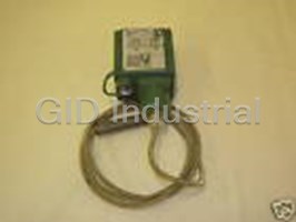
SQUARE D 9025-GXW2
Description
TEMPERATURE SWITCH 480VAC 10AMP
Part Number
9025-GXW2
Price
Request Quote
Manufacturer
SQUARE D
Lead Time
Request Quote
Category
PRODUCTS - 9
Datasheet

Extracted Text
Industrial Pressure Switches Class 9012/9016/9025 CATALOG CONTENTS Description . . . . . . . . . . . . . . . . . . . . . . . . . . . . . . . . . . . . . . . . . . . . . . . . . . . . .Page Class 9012 . . . . . . . . . . . . . . . . . . . . . . . . . . . . . . . . . . . . . . . . . . . . . . . . . . . . . . 3-16 Class 9016 . . . . . . . . . . . . . . . . . . . . . . . . . . . . . . . . . . . . . . . . . . . . . . . . . . . . . 17-18 Class 9025 . . . . . . . . . . . . . . . . . . . . . . . . . . . . . . . . . . . . . . . . . . . . . . . . . . . . . 19-20 Type XML, Type XMLE . . . . . . . . . . . . . . . . . . . . . . . . . . . . . . . . . . . . . . . . . . . . 21-60 Courtesy of Steven Engineering, Inc.-230 Ryan Way, South San Francisco, CA 94080-6370-Main Office: (650) 588-9200-Outside Local Area: (800) 258-9200-www.stevenengineering.com 2 © 1998 Square D All Rights Reserved 5/98 Courtesy of Steven Engineering, Inc.-230 Ryan Way, South San Francisco, CA 94080-6370-Main Office: (650) 588-9200-Outside Local Area: (800) 258-9200-www.stevenengineering.com Industrial Pressure Switches Class 9012, Type G–Description DESCRIPTION The Class 9012 Type G pressure switches are UL Listed and CSA CertiŢed as industrial control equipment. They are used to interface pneumatic or hydraulic systems with electrical control systems by opening or closing electrical contacts in response to pressure changes in the system. They have outstanding repeatability and drift performance. Their efŢcient design uses durable, low mass components for excellent performance under heavy duty vibration and shock conditions. The Type G pressure switches includes diaphragm and piston actuated devices with a variety of modiŢcations (see page 14). Type G diaphragm switches range from 0.2-675 psi falling pressure. Buna-N diaphragms and zinc plated steel ţanges are standard. Diaphragms of Viton and ethylene propylene are available as well as stainless steel ţanges. Type G piston actuated switches range from 20-9,000 psi falling pressure. They have sealed pistons and can be used on air, water, oil, or any media compatible with the actuator material. Piston actuated switches come standard with stainless steel pistons and housings, VITON diaphragms and o-ring seals, and Teţon retaining rings. Ethylene propylene diaphragms and o-ring seals are also available. Features for both diaphragm and piston actuated pressure switches include: • High shock resistance • Dual numerical range scale (psi and kPa) • High set point stability • SPDT or DPDT double break contacts • Adjustable or nonadjustable differential • Internal or external range adjustment • No drain line required • Single stage operation • Dual stage operation • Differential pressure operation Type G industrial switches are available as open type or in NEMA Type 1 enclosures. The backplate is steel with a plastic cover. Open type devices in pressure ranges up to 250 psi are available with internal or external threaded pressure connectors making them ideally suited for panel mounting. Type G machine tool switches have NEMA Type 4, 4X, or 13 (IEC IP66) cast aluminum enclosures. These devices are UL Listed and CSA CertiŢed as industrial control equipment. They are UL Listed for use in Class II, Division 2, Group G and Class III hazardous locations. They are also UL Marine Listed for use on vessels greater than 65 feet long where ignition protection is not required. Type G machine tool switches are also available in NEMA Type 7 & 9 cast iron enclosures. These are UL Listed for use in Class I, Divisions 1 and 2, Groups C and D, and Class II, Divisions 1 and 2, Groups E, F, G hazardous locations. 3 © 1998 Square D All Rights Reserved 5/98 Courtesy of Steven Engineering, Inc.-230 Ryan Way, South San Francisco, CA 94080-6370-Main Office: (650) 588-9200-Outside Local Area: (800) 258-9200-www.stevenengineering.com Industrial Pressure Switches Class 9012, Type G–Application and General Information APPLICATION AND GENERAL INFORMATION Pressure switches are used in a wide variety of applications such as: • compressors • HVAC equipment • chillers • pumping systems • machine tools • stamping presses • automatic grinders • welders • process equipment • molding machines Generally, Class 9012 pressure switches can be used in any application where electrical contacts must open or close in response to a system pressure change, within the electrical and pressure ratings of the switch. Two typical functions of a pressure switch are to: • Monitor the pressure in the system. The switch can be used as either an interlock that will sequence operations in an automatic system, or to give an audio or visual signal, typically an alarm of an undesired condition, at predetermined pressures. • Control the pressure in the system by starting and stopping a pump or a compressor at predetermined pressures. Normally a switch with a nonadjustable differential is used in applications that monitor the pressure. An adjustable differential switch is usually necessary in applications that require the switch to control the pressure. Bellows vs. Diaphragm The three factors that affect bellows life are the compatibility of the pressure medium with the bellows and bellows housing material, the amount of pressure change during each operating cycle, and the speed of operation. On wide pressure change applications, the bellows is ţexed over a wide portion of the range on each operating cycle causing the metal to fatigue faster than if it ţexes over a small portion such as between the operating points only. This will reduce life. The Type G is offered with either diaphragm or piston actuators only — for maximum versatility, speed of operation, and life. Diaphragm life, like bellows life, is affected by pressure medium compatibility. Standard diaphragms on Class 9012 Type G devices are nitrile (Buna-N) in zinc plated steel ţanges. Fluorocarbon (VITON ) and ethylene propylene diaphragms as well as Type 316 stainless steel ţanges are also available. The elastomer diaphragms used on Class 9012 switches are capable of withstanding high speed cycling and wide pressure changes. Operating speeds up to 200 cycles per minute are not detrimental to the life of the diaphragm. Surges which exceed the maximum range value may occasionally occur, especially on start-up of the machine (see section on surges). The switch will withstand these occasional surges if they are within the maximum allowable pressure rating of the switch. However, frequently applying this higher pressure will greatly reduce the life of the switch. Although the diaphragm will withstand wide pressure changes on each operating cycle, the pressure applied to the diaphragm during the normal operating cycle should never exceed the maximum value listed in the “Range” column in the catalog listing. Life will be considerably reduced if regularly cycled above this pressure. If signiŢcant surges are common or if pressures are higher than listed in the “Range” column, consider the use of a piston device. 4 © 1998 Square D All Rights Reserved 5/98 Courtesy of Steven Engineering, Inc.-230 Ryan Way, South San Francisco, CA 94080-6370-Main Office: (650) 588-9200-Outside Local Area: (800) 258-9200-www.stevenengineering.com Industrial Pressure Switches Class 9012, Type G–Application and General Information Surges One of the most destructive elements to a pressure switch is the hydraulic surge. A surge is a high rate of rise in pressure, normally of short duration, caused by starting a pump or opening and closing a valve. Extremely high rates of rise in pressure can be damaging even though they are within the limits of the maximum allowable pressure. To limit the effect of surges, the switch should be mounted as close to an accumulator and as far from the pump or quick acting valve as possible. Type G piston actuated switches are supplied with a 0.020" pressure oriŢce to help reduce the effects of minor surges. Type G diaphragm actuated switches are supplied with a 0.060" pressure oriŢce. A restrictor with a small oriŢce placed in the line between the switch and pump or valve will further help to protect the switch. Using a surge snubber such as the Class 9049 Types A26 or A26S will also protect the switch. Vibration Among other things, excessive vibration can cause contact bounce, chatter or premature contact transfer especially when system pressure is near the operating point of the switch. Remote mounting of the switch is the best way to avoid problems. Use On Steam Switches should not be applied directly on steam exceeding 15 psig. However, with the installation of a Class 9049 Type A7A steam capillary tubing kit between the pressure connection and the switch, steam pressure up to 250 psig may be applied provided this does not exceed the maximum allowable pressure rating of the switch or the maximum temperature rating at the actuator. Piston vs. Diaphragm Selecting between piston and diaphragm devices depends on several criteria: 1) maximum allowable pressure, 2) range and differential, 3) surges and 4) media, whether hydraulic or pneumatic. Maximum allowable pressures for piston devices are much higher than for diaphragm devices. Most diaphragm devices have a maximum allowable pressure of 850 psi or less, where all piston devices have a maximum allowable pressure of 10,000 psi or more. Range and differential for diaphragm devices are lower than for piston devices. Many applications call for a low differential, ie: 20 psi, which may exclude piston devices which have a minimum differential of 60 psi or more. Surges are a part of every hydraulic system, and while many are small and have only a small effect on the switch, some are signiŢcant and can potentially destroy a pressure switch. Diaphragm devices are the most sensitive to surges and will be damaged most easily. Piston devices are more tolerant of surges and will last longer in the same application. Hydraulic systems, which typically use oil based media, are more demanding on a system because they are usually at higher pressures, have wider pressure variations and produce more surges since the media does not compress. Pneumatic systems, which are typically air, are less demanding on a system since they are usually at lower pressures and the medium can compress itself to cushion the effects of surges. As a guide, follow these basic steps: High maximum allowable pressures: . . . . . . . . . . . . . . . . . . . . . . . . . . . . . . . . . . . . . . . . . . . . . . . piston Lower maximum allowable pressures: . . . . . . . . . . . . . . . . . . . . . . . . . . . . . . . . . . . . . . . . . diaphragm Low differentials or pressures:. . . . . . . . . . . . . . . . . . . . . . . . . . . . . . . . . . . . . . . . . . . . . . . . diaphragm High pressures: . . . . . . . . . . . . . . . . . . . . . . . . . . . . . . . . . . . . . . . . . . . . . . . . . . . . . . . . . . . . . . . piston Minimal surges: . . . . . . . . . . . . . . . . . . . . . . . . . . . . . . . . . . . . . . . . . . . . . . . . . . . . diaphragm or piston Constant surges: . . . . . . . . . . . . . . . . . . . . . . . . . . . . . . . . . . . . . . . . . . . . . . . . . . . . . . . . . . . . . . piston Hydraulic systems:. . . . . . . . . . . . . . . . . . . . . . . . . . . . . . . . . . . . . . . . . . . . . . . . . . . . . . . . . . . . . piston Pneumatic systems: . . . . . . . . . . . . . . . . . . . . . . . . . . . . . . . . . . . . . . . . . . . . . . . . . . . . . . . diaphragm 5 © 1998 Square D All Rights Reserved 5/98 Courtesy of Steven Engineering, Inc.-230 Ryan Way, South San Francisco, CA 94080-6370-Main Office: (650) 588-9200-Outside Local Area: (800) 258-9200-www.stevenengineering.com Industrial Pressure Switches Class 9012, Type G–Application and General Information Piston Life For long piston life, the pressure medium should be Ţltered to keep foreign matter such as dirt and chips out of the piston assembly. Type G sealed piston devices are not recommended for use on dry gas media since there could be some leakage past the seal. The amount of leakage will depend on the gas, media pressure and rate of operation. It is possible the switch would be inoperative. Dual Stage Pressure Switches The Type G is available with dual stage switches and provide two distinct levels of control from one device. These switches are most commonly used where dual functions are required or in sequencing applications such as alarm-shutdowns. Differential Pressure Switches The Type G is also available as a differential switch. These devices are used to monitor the change in the difference between two pressures. They are unidirectional devices and used in applications to signal that a predetermined pressure difference has been reached as a result of a widening or increasing difference between the pressures. They can also be used in applications to signal that a predetermined difference has been reached as a result of a narrowing or decreasing pressure difference between the two pressures. Summary While a pressure switch may perform satisfactorily in one application, it may prove to be unsatisfactory in a different application. Therefore, the deciding factor in the selection of a pressure switch should be based on the requirements of the application being considered. When specifying a pressure switch, note the following: • To ensure repeatability and minimize setting drift, pressure settings should fall within the middle 80% of the pressure range. When the pressure settings approach 10% of the minimum or maximum end of the pressure range, select a switch with a lower or higher pressure range, respectively. • When switches are required to be factory set and only one setting is identiŢed, specify whether this setting is on increasing or decreasing pressure. • The pressure applied to a diaphragm actuated switch during a normal cycle should never exceed the maximum range value listed for the switch. The life of the switch will be reduced if the switch is regularly cycled above the maximum range value. • Ensure the switch is rated to withstand any pressure surges that may occur at the switch location in the system. Any anticipated pressure surges should be less than the maximum allowable pressure listed for the switch. • Ensure the wetted parts of the switch are compatible with the system ţuid. • If system response time is critical, select a switch with a volumetric displacement that is compatible with the overall system. See table 1. Table 1: Volumetric Displacement of Class 9012 Type Pressure Switches Volumetric Displacement (1) Volumetric Displacement (1) Class 9012 Type 3 3 (in ) (cm ) GAR, GAW, GDR, GDW-1& 21 0.20774 3.40422 GAR, GAW, GDR, GDW-2 & 22 0.07040 1.15385 GAR, GAW, GDR, GDW-4 & 24 0.04320 0.70805 GAR, GAW, GDR, GDW-5 & 25 0.02144 0.35140 GAR, GAW, GDR, GDW-6 & 26 0.01376 0.22553 GBR, GBW, GER, GEW-1 & 21 0.00200 0.13112 GBR, GBW, GER, GEW-2 & 22 0.00512 0.08392 GCR, GCW, GFR, GFW-1 & 21 0.00320 0.05245 GCR, GCW, GFR, GFW-2 & 22 0.00117 0.01922 GCR, GCW, GFR, GFW-3 & 23 0.00060 0.00924 GCR, GCW, GFR, GFW-4 & 24 0.00037 0.00612 (1) Figures shown are total displacement. When switch is operated between settings only, displacement will be 1/3 of values shown. 6 © 1998 Square D All Rights Reserved 5/98 Courtesy of Steven Engineering, Inc.-230 Ryan Way, South San Francisco, CA 94080-6370-Main Office: (650) 588-9200-Outside Local Area: (800) 258-9200-www.stevenengineering.com Industrial Pressure Switches Class 9012, Type G–Technical Overview TECHNICAL OVERVIEW Operating Points (Settings) Every pressure switch has two operating points; one on rising pressure and one of falling pressure. The operating point on rising pressure is referred to as the TRIP POINT and the operating point on falling pressure is referred to as the RESET POINT. These operating points are called the SETTINGS of the switch. — TRIP POINT (rising pressure) — RESET POINT (falling pressure) Differential The differential is the difference in pressure between the trip point and the reset point. It can be adjustable or nonadjustable (Ţxed). Adjustable Differential Fixed Differential Max. Maximum Trip Differential Point Adjustable Differential Min. } Minimum Trip Trip Differential Point Point Fixed Differential } Reset Reset Point Point 0 psi 0 psi Range The range is the pressure limits within which the operating points (settings) can be adjusted. The range of the Class 9012 pressure switch is referenced to the operating point on falling pressure (reset point). The differential adds to the reset point setting and determines the operating point on rising pressure (trip point). To determine the operating range on rising pressure for a nonadjustable (Ţxed) differential type switch, the differential is added to both the low end of the range and the high end of the range. For example, to determine the range on rising pressure for a Class 9012 Type GDW5: 1. Range on falling pressure = 3 to 150 psi 2. Nonadjustable differential = 6.0 – 0.8 psi 3. Range on rising pressure = 9 – 0.8 to 156 – 0.8 psi 7 © 1998 Square D All Rights Reserved 5/98 Courtesy of Steven Engineering, Inc.-230 Ryan Way, South San Francisco, CA 94080-6370-Main Office: (650) 588-9200-Outside Local Area: (800) 258-9200-www.stevenengineering.com Maximum Allowable Pressure Adjustable Range - Rising Pressure Adjustable Range - Falling Pressure Maximum Allowable Pressure Adjustable Range - Rising Pressure Adjustable Range - Falling Pressure Industrial Pressure Switches Class 9012, Type G–Technical Overview For adjustable differential type switches, add the minimum differential to the low end of the range and the maximum differential to the high end of the range. For example, to determine the range on rising pressure for a Class 9012 Type GAW5: 1. Range on falling pressure = 3 to 150 psi 2. Adjustable differential = 6.0 to 30 psi 3. Range on rising pressure = 9 to 180 During the normal operating cycle, system pressure should never exceed the upper limit of the range when using a diaphragm actuated switch. This will greatly reduce the life of the diaphragm. Maximum Allowable Pressure Maximum allowable pressure is the pressure to which a switch can be subjected without causing a change in operating characteristics, shift in settings, or damage to the device. Pressure surges may occur in a system during the start up of a machine or from valve operation. Surges are not normally detrimental to the life of a switch if the surge is within the maximum allowable pressure rating of the switch. Diaphragm actuated switches should not be subjected to more than 10 surges per day. More frequent surges will greatly reduce the life of the diaphragm. 8 © 1998 Square D All Rights Reserved 5/98 Courtesy of Steven Engineering, Inc.-230 Ryan Way, South San Francisco, CA 94080-6370-Main Office: (650) 588-9200-Outside Local Area: (800) 258-9200-www.stevenengineering.com 3 4 1 2 Industrial Pressure Switches Class 9012, Type G–Specifications SPECIFICATIONS Contact Arrangement Type G Machine Tool, Temperature & Vacuum (except GVG) Type Contact Arrangement Contact Symbol Single Pole 1 N.O. – 1 N.C. SAME Double Throw POLARITY Snap switch contains two (2) double break contact elements (1 N.O. – and 1 N.C.) that must be used on circuits of same polarity. Type Contact Arrangement Contact Symbol Double Pole 2 N.O. – 2 N.C. Double Throw SAME POLARITY Snap switch contains two electrically separated sets of contact elements allowing use on circuits of opposite polarity. Each set contains two double break contact elements (1 N.O. and 1 N.C.) that must be used on circuits of same polarity. Type G Industrial Contact Arrangement Contact Symbol 1 N.O. – 1 N.C. Contacts are single pole, double throw — one circuit normally open and one circuit normally closed. These circuits are not electrically separate and can not be used on opposite polarities. Circuit Ratings AC – 50 or 60 Hz DC AC or DC Resistive Inductive Inductive 75% Power 35% Power Factor and Resistive Factor Continuous Contacts Volts Volts Make and Break Carrying Make Break Make and Amperes Amperes Break Single Double Amperes Amps. VA Amps. VA Throw Throw 120 60 7200 6 720 6 125 0.55 0.22 10 240 30 7200 3 720 3 250 0.27 0.11 10 SPDT 480 15 7200 1.5 720 1.5 600a 0.10 . . . . 10 600 12 7200 1.2 720 1.2 . . . . . . . . . . . . . . . . 120 60 7200 6 720 6 125 0.22 0.22 10 240 30 7200 3 720 3 250 0.11 0.11 10 DPDT 480 15 7200 1.5 720 1.5 600 . . . . . . . . 10 600 12 7200 1.2 720 1.2 . . . . . . . . . . . . . . . . a 600 volt DC rating does not apply. Acceptable Wire Sizes . . . . . . . . . . . . . . . . . . . . . . . . . . . . . . . . . . . . . . . . . . . . . . . . . . . . .#12-22 AWG Recommended Terminal Clamp Torque. . . . . . . . . . . . . . . . . . . . . . . . . . . . . . . . . . . . . . . . . . . . 7 in-lbs Temperature Ratings Actuator Minimum Maximum Ambient All -23 °C (-10 ˚F) +85 °C (+185 °F) Diaphragm -40 °C (-40 ˚F) Media Piston -26 °C (-15 ˚F) +120 °C (+250 °F) All with Forms Q4 and Q14 -26 °C (-15 ˚F) 9 © 1998 Square D All Rights Reserved 5/98 Courtesy of Steven Engineering, Inc.-230 Ryan Way, South San Francisco, CA 94080-6370-Main Office: (650) 588-9200-Outside Local Area: (800) 258-9200-www.stevenengineering.com SAME POLARITY Industrial Pressure Switches Class 9012, Type G–Dimensions DIMENSIONS Types GNG, GPG, GQG, GRG, GSG, and GTG Industrial Pressure Switches 1.62 Hole for 41 (2) 0.20 Dia. 1/2 Conduit .82 21 5 Mounting Hole 1.38 35 4.13 3.59 105 91 5.03 128 5.53 140 3.22 82 1.60 41 A 1.03 1.11 2.21 26 28 1/4 - 18 NPTF 56 2.06 2.75 Int. Thread 52 70 Type A Dimension, in(mm) GNG, GRG - 3, 4, 5, 6 1.41 (36) GPG, GSG - 1, 2, 3 1.31 (33) GQG, GTG - 1, 2, 3, 4 2.24 (57) Types GAW, GBW, GCW, GDW, GEW, GFW, GKW, GLW, and GMW Machine Tool Switches 3.50 FORM K 89 1.13 2.63 29 0.88 67 2.72 22 0.48 69 12 0.38 2.30 10 0.40 0.48 58 FORM K1 10 12 0.17 4 FORMS E1, E2, E3, E4 3.60 91 0.27 7 2.72 (2) DIA. 69 MTG. HOLES FORMS G17, G18, G19, G20, G21, G22, & T4 0.38 10 D65075 - 166 IN A DUAL DIMENSIONS MM 1/2 - 14 NPT CONDUIT CONNECTION 1.22 0.58 1.61 1/4 - 18 NPTF 31 15 41 PIPE THREAD Type A Dimension, in(mm) GAW, GDW, GKW - 2, 4, 5, 6 2.33 (59) 22, 24, 25, 26 GBW, GEW, GLW - 1, 2, 21 2.23 (57) GCW, GFW, GMW - 1, 2, 3, 4 3.15 (80) 21, 22, 23, 24 10 © 1998 Square D All Rights Reserved 5/98 Courtesy of Steven Engineering, Inc.-230 Ryan Way, South San Francisco, CA 94080-6370-Main Office: (650) 588-9200-Outside Local Area: (800) 258-9200-www.stevenengineering.com Industrial Pressure Switches Class 9012, Type G–Selection and Modifications SELECTION & MODIFICATIONS Type G Machine Tool Switches Class 9012 single stage pressure switches are control circuit rated devices. These switches are used in pneumatic or hydraulic systems on a wide variety of machine and process applications to protect the equipment. They either control or monitor the system pressure. Nonadjustable Differential h NEMA Type 4, 4X, 13 Enclosure UL Listed And CSA CertiŢed As Industrial Control Equipment c Single Pole Double Pole Range On Decreasing qApproximate Differential At Maximum Allowable Double Throw Double Throw Pressure PSIG Mid Range — PSIG Pressure PSIG Type Type Diaphragm Actuated – Nitrile (Buna-N) Diaphragm, Zinc Plated Steel Housing .2-10 .6 – .1 100 GDW1 GDW21 1-40 1.6 – .4 100 GDW2 GDW22 1.5-75 3.0 – .5 240 GDW4 GDW24 3-150 6.0 – .8 475 GDW5 GDW25 5-250 10.0 – 1.5 750 GDW6 GDW26 13-425 16 – 3.5 850 GEW1 GEW21 20-675 27 – 5 2000 GEW2 GEW22 Piston Actuated – #440 Stainless Steel Piston. ® ® #303 Stainless Steel Housing, Fluorocarbon (VITON ) Diaphragm and O-ring, TEFLON Retaining Ring 20-1000 59 – 9 10000 GFW1 GFW21 90-2900 170 – 15 15000 GFW2 GFW22 170-5600 289– 55 20000 GFW3 GFW23 270-9000 495 – 70 25000 GFW4 GFW24 h For metric threads, add M after the W on all types. Nonadjustable Differential NEMA Type 7 & 9 Enclosure Class I & II, Division 1 & 2, Groups C, D, E, F, G UL Listed As Industrial Control Equipment a Single Pole Double Pole Range On Decreasing qApproximate Differential At Maximum Allowable Double Throw Double Throw Pressure PSIG Mid Range - PSIG Pressure PSIG Type Type Diaphragm Actuated – Nitrile (Buna-N) Diaphragm, Zinc Plated Steel Housing .2 - 10 1.0 – .1 100 GDR1 GDR21 1 - 40 2.4 – .8 100 GDR2 GDR22 1.5 - 75 4.5 – 1 240 GDR4 GDR24 3 - 150 9 – 1.5 475 GDR5 GDR25 5 - 250 15 – 3 750 GDR6 GDR26 13 - 425 25 – 7 850 GER1 GER21 20 - 675 41 – 10 2000 GER2 GER22 Piston Actuated – #440 Stainless Steel Piston. ® ® #303 Stainless Steel Housing, Fluorocarbon (VITON ) Diaphragm and O-ring, TEFLON Retaining Ring 20-1000 89 – 18 10000 GFR1 GFR21 90-2900 255 – 30 15000 GFR2 GFR22 170-5600 578 – 110 20000 GFR3 GFR23 270-9000 788 – 140 25000 GFR4 GFR24 c UL Marine Listed for use on ships/vessels greater than 65 feet long where ignition protection is not required. Also UL Listed for use in Class II, Division 2, Group G and Class III hazardous locations. a UL Marine Listed for use on vessels greater than 65 feet long where ignition protection is required. q Differential adds to range setting and determines operating point on rising pressure. NOTE: When switches are required to be factory set and only one setting is identiŢed, specify whether this setting is on increasing or decreasing pressure. File E12442 CCN NOWT G*W, G*R Marking File E12158 CCN NKPZ G*O, G*G File E12443 CCN NTHT (marine use) Complies with IEC 957.5.1, 5C8.3.4 when protected with a File LR 25490 Class 3211 03 G*W, G*O, G*G Bussman Class CC KTK-R-10 File LR 26817 Class 3218 02 G*R fuse. 11 © 1998 Square D All Rights Reserved 5/98 Courtesy of Steven Engineering, Inc.-230 Ryan Way, South San Francisco, CA 94080-6370-Main Office: (650) 588-9200-Outside Local Area: (800) 258-9200-www.stevenengineering.com Industrial Pressure Switches Class 9012, Type G–Selection and Modifications Adjustable Differential h NEMA Type 4, 4X, 13 Enclosure UL Listed And CSA CertiŢed As Industrial Control Equipment c Single Pole Double Pole Range On Decreasing qAdjustable Differential Maximum Allowable Double Throw Double Throw Pressure PSIG Approximate at Mid Range Pressure PSIG Type Type Diaphragm Actuated - Nitrile (Buna-N) Diaphragm, Zinc Plated Steel Housing .2 - 10 .6 - 2 100 GAW1 GAW21 1 - 40 1.6 - 8 100 GAW2 GAW22 1.5 - 75 3.5 - 15 240 GAW4 GAW24 3 - 150 6.0 - 30 475 GAW5 GAW25 5 - 250 10.0 - 49 750 GAW6 GAW26 13 - 425 16 - 90 850 GBW1 GBW21 20 - 675 27 - 130 2000 GBW2 GBW22 Piston Actuated – #440 Stainless Steel Piston. ® ® #303 Stainless Steel Housing, Fluorocarbon (VITON ) Diaphragm and O-ring, TEFLON Retaining Ring 20 - 1000 59 - 200 10000 GCW1 GCW21 90 - 2900 170 - 560 15000 GCW2 GCW22 170 - 5600 289 - 1260 20000 GCW3 GCW23 270 - 9000 495 - 1900 25000 GCW4 GCW24 h For metric threads, add M after the W on all types. Adjustable Differential NEMA Type 7 & 9 Enclosure Class I & II, Division 1 & 2, Groups C, D, E, F, G UL Listed As Industrial Control Equipment a Single Pole Double Pole Range On Decreasing qAdjustable Differential Maximum Allowable Double Throw Double Throw Pressure PSIG Approximate at Mid Range Pressure PSIG Type Type Diaphragm Actuated – Nitrile (Buna-N) Diaphragm, Zinc Plated Steel Housing .2 - 10 1.0 - 2 100 GAR1 GAR21 1 - 40 2.4 - 8 100 GAR2 GAR22 1.5 - 75 4.5 - 15 240 GAR4 GAR24 3 - 150 9 - 35 475 GAR5 GAR25 5 - 250 15 - 49 750 GAR6 GAR26 13 - 425 25 - 90 850 GBR1 GBR21 20 - 675 41 - 130 2000 GBR2 GBR22 Piston Actuated – #440 Stainless Steel Piston. ® ® #303 Stainless Steel Housing, Fluorocarbon (VITON ) Diaphragm and O-ring, TEFLON Retaining Ring 20 -1000 89 - 200 10000 GCR1 GCR21 90 - 2900 255 - 560 15000 GCR2 GCR22 170 - 5600 578 - 1260 20000 GCR3 GCR23 270 - 9000 788 - 1900 25000 GCR4 GCR24 c UL Marine Listed for use on ships/vessels greater than 65 feet long where ignition protection is not required. Also UL Listed for use in Class II, Division 2, Group G and Class III hazardous locations. a UL Marine Listed for use on vessels greater than 65 feet long where ignition protection is required. q Differential adds to range setting and determines operating point on rising pressure. NOTE: When switches are required to be factory set and only one setting is identiŢed, specify whether this setting is on increasing or decreasing pressure. Marking Complies with IEC 957.5.1, 5C8.3.4 when protected with a Bussman Class CC KTK-R-10 fuse. File E12442 CCN NOWT G*W, G*R File E12158 CCN NKPZ G*O, G*G File E12443 CCN NTHT (marine use) File LR 25490 Class 3211 03 G*W, G*O, G*G File LR 26817 Class 3218 02 G*R 12 © 1998 Square D All Rights Reserved 5/98 Courtesy of Steven Engineering, Inc.-230 Ryan Way, South San Francisco, CA 94080-6370-Main Office: (650) 588-9200-Outside Local Area: (800) 258-9200-www.stevenengineering.com Industrial Pressure Switches Class 9012, Type G–Selection and Modifications Differential Pressure Switch Differential pressure switches are used to monitor the change in the difference between two pressures. Type G differential pressure switches are unidirectional devices and are used in applications to signal that a predetermined pressure difference has been reached as a result of a widening or increasing difference between the two pressures. They can also be used in applications to signal that a predetermined pressure difference has been reached as a result of a narrowing or decreasing difference between the two pressures. NEMA Type 4, 4X, 13 Enclosures UL Listed And CSA CertiŢed As Industrial Control Equipment c Adjustable Difference Adjustable Differential Single Pole Double Pole Working Pressure Maximum on Decreasing Pressure Actuates on Increasing Double Throw Double Throw Range on Decreasing Allowable (adds to working pressure) Pressure (adds to X (upper) Actuator Pressure Type Type Y (lower) Actuator adjustable difference) Diaphragm Actuated – Nitrile (Buna-N) Diaphragm, Zinc Plated Steel Housing 0 - 75 .25 - 10 .8 - 2 100 GGW1 GGW21 0 - 175 .5 - 36 5 - 15 240 GGW4 GGW24 0 - 500 3 - 175 22 - 90 850 GHW1 GHW21 Piston Actuated – #440 Stainless Steel Piston. ® ® #303 Stainless Steel Housing, Fluorocarbon (VITON ) Diaphragm and O-ring, TEFLON Retaining Ring 0 - 5000 15 - 825 80-200 7500 GJW1 GJW21 c UL Listed for use in Class II, Division 2, Group G and Class III hazardous locations. Also, UL Marine Listed for use on vessels greater than 65 feet long where ignition protection is not required. Dual Stage Pressure Switch Class 9012 Type G dual stage pressure switches are designed for use in applications where two separate pressure operations must be controlled by a single pressure monitoring device. These controls are most commonly used where dual functions are required or in sequencing applications such as alarm shutdowns. Dual Stage Pressure Switch NEMA Type 4, 4X, 13 Enclosure UL Listed And CSA CertiŢed As Industrial Control Equipment c Fixed Differential — Add to Low Range Setting Limits of Adjustable Spread Adds to SPDT (decreasing) Operating Point to Maximum Pressure Between Which Range Setting to Obtain each Obtain Approximate High (rising) Allowable Stage 1 can be Adjusted to Decreasing Operating Point Stage Operating Point of Each Stage Pressure Operate on Decreasing Pressure of Stage 2 Stage 1 Stage 2 Type Diaphragm Actuated – Nitrile (Buna-N) Diaphragm, Zinc Plated Steel Housing .2 - 10 1 - 5 1.0 – 0.2 1.5 – 0.4 100 GKW1 1 - 40 4 - 20 4.0 – 1.0 6.0 – 1.5 100 GKW2 1.5 - 75 6 - 30 5.0 – 1.5 8.0 – 2.0 240 GKW4 3 - 150 12 - 75 8.0 – 2.0 12 – 3 475 GKW5 5 - 250 22 - 110 14 – 3 21 – 5 750 GKW6 13 - 425 40 - 180 20 – 4 30 – 7.5 850 GLW1 20 - 675 45 - 250 30 – 6 45 – 11 2000 GLW2 Piston Actuated – #440 Stainless Steel Piston. ® ® #303 Stainless Steel Housing, Fluorocarbon (VITON ) Diaphragm and O-ring, TEFLON Retaining Ring 20 - 1000 50 - 300 50 – 10 75 – 19 10000 GMW1 90 - 2900 140 - 800 140 – 30 210 – 52 15000 GMW2 170 - 5600 300 - 1700 275 – 60 400 – 100 20000 GMW3 270 - 9000 500 - 2500 400 – 80 800 – 150 25000 GMW4 c UL Listed for use in Class II, Division 2, Group G and Class III hazardous locations. Also UL Marine Listed for use on vessels greater than 65 feet long where ignition protection is not required. 13 © 1998 Square D All Rights Reserved 5/98 Courtesy of Steven Engineering, Inc.-230 Ryan Way, South San Francisco, CA 94080-6370-Main Office: (650) 588-9200-Outside Local Area: (800) 258-9200-www.stevenengineering.com Industrial Pressure Switches Class 9012, Type G–Selection and Modifications Class 9012, Type G, Machine Tool ModiŢcations ModiŢcation Applies To: Form Standard on GAW, GAWM, GDW, GDWM, GGW, GKW1, 21 only. Available Side conduit hub not available separately nor as a replacement. B2 on all other GAW thru GMW, GAWM thru GFWM. Standard with Forms E2, E3, E4, K, K1, M14. Available on all GAW thru Removable conduit hub GMW and GAWM thru GFWM except Types 1 and 21. Standard on Types B4 GGW4 & 24, GHW & GJW. ® Fluorocarbon (VITON ) Enclosure Gaskets All Types except NEMA 7 and 8. D6 Pull-to-test button GAW thru GFW and GAWM thru GFWM only. E2 Lock on rising pressure, manual reset only Available on GDW, GDWM, GEW, GEWM, GFW, GFWM only. E3 Lock on falling pressure, manual reset only Available on GDW, GDWM, GEW, GEWM, GFW, GFWM only. E4 Mounting feet (factory installed only) GAW, GAWM, GDW, GDWM, GGW, GKW1, 21 only. F 120 Volt AC or DC neon pilot light with clear lens G17 Available on all GAW thru GMW, GAWM thru GFWM. with red lens G18 240 Volt AC or DC neon pilot light with clear lens For replacement pilot lights: G19 with red lens See 9998 PC-303 through 305. G20 For pilot light conversion kits: 24 Volt DC only LED with clear lens G21 See 9998 PC-306 through 308. with red lens G22 Complete Class and Type information required. SPDT snap switch rated 1.1 Amp at 125 VDC (minimum differential Available on GAR thru GFR, GAW thru GJW, GAWM thru GFWM. H3 doubles) Prewired 5 pin Brad Harrison male receptacle #41310 or H10 interchangeable Crouse-Hinds receptacle at our convenience. For Available on GAW thru GJW single pole devices only. See diagrams or use with Brad Harrison female portable plug #41306, 41307, 41308 below. H11 or equal External range adjustment (includes knob and range scale window) GAW thru GFW, GAWM thru GFWM, GKW thru GMW. K External range adjustment slotted for screwdriver (includes range GAW thru GFW, GAWM thru GFWM, GKW thru GMW. K1 scale window) Pg 13.5 conduit thread and 1/4 - 19 BSP pressure connection. GAW thru GFW, GKW thru GMW M12 1 G / " BS2779 parallel pipe thread on pressure connection. GGW, GHW, GJW M14 4 GAW thru GFW, GKW thru GMW M14 GGW, GHW O1 Actuator prepared for oxygen service GAR, GBR, GDR, GER, GAW, GBW, GDW, GEW, GAWM, GBWM, O1 GDWM, GEWM, GKW, GLW GGW-1, 21 only. Q1 All other GGW, GHW only. Q1 Standard Nitrile (Buna-N) diaphragm in #316 stainless steel ţange GAR, GAW, GDR, GDW, GAWM, GDWM, GKW1, 21 only. Q1 All other GAR, GBR, GDR, GER, GAW, GBW, GDW, GEW, GAWM, Q1 GBWM, GDWM, GEWM, GKW, GLW Available on all GGW, GHW except GGW-1, 21. Q3 Ethylene propylene diaphragm in #316 stainless steel ţange Available on all GAR, GBR, GDR, GER, GAW, GBW, GDW, GEW, GAWM, Q3 GBWM, GDWM, GEWM, GKW, GLW except Types 1 and 21. GGW1, 21 only. Q4 All other GGW, GHW. Q4 GAR, GAW, GBR, GBW, GDR, GDW, GER, GEW, GAWM, GBWM, ® Fluorocarbon (VITON ) diaphragm in #316 stainless steel ţange Q4 GDWM, GEWM, GKW-1, 21 only. All other GAR, GAW, GBR, GBW, GDR, GDW, GER, GEW, GAWM, Q4 GBWM, GDWM, GEWM, GKW, GLW. GJW only. Q5 Ethylene propylene diaphragm and O-ring GCR, GCW, GFR, GFW, GCWM, GFWM, GMW Q5 Available on all GGW, GHW except GGW1, 21. Q13 Ethylene propylene diaphragm in standard zinc plated steel ţange Available on all GAR, GBR, GDR, GER, GAW, GBW, GDW, GEW, GAWM, Q13 GBWM, GDWM, GEWM, GKW, GLW except Types 1 and 21. GGW1, 21 only. Q14 All other GGW, GHW. Q14 ® Fluorocarbon (VITON ) diaphragm in standard zinc plated steel GAR, GAW, GBR, GBW, GDR, GDW, GER, GEW, GAWM, GBWM, Q14 ţange GDWM, GEWM, GKW1, 21 only All other GAR, GAW, GBR, GBW, GDR, GDW, GER, GEW, GAWM, Q14 GBWM, GDWM, GEWM, GKW, GLW Range scale window (standard with Forms K and K1) GAW thru GMW, GAWM thru GFWM. V1 GAR, GAW, GDR, GDW, GGW, GKW. Not available in combination with 1 / "-18 NPT external thread pressure connection Z 4 Forms Q1, Q3, Q4. Fungus prooŢng per MIL-T-152B with varnishes per MIL-V-173A All Types. Z12 1 1 / "-14 NPT external thread, / "-18 NPTF internal thread pressure GAR, GAW, GDR, GDW, GGW, GKW. Not available in combination with 2 4 Z16 connection Forms Q1, Q3, Q4. GAR thru GFR; GAW thru GMW. Not available in combination with Forms 7 / "-20 UNF-2B internal thread pressure connection Z18 16 Q1, Q3, Q4. ORG ORG RED WHT BLK GRN 4 8 GRN 4 8 3 4 2 3 BLK 4 2 5 1 26 26 RED 5 1 1 1 WHT FORM H10 FORM H11 14 © 1998 Square D All Rights Reserved 5/98 Courtesy of Steven Engineering, Inc.-230 Ryan Way, South San Francisco, CA 94080-6370-Main Office: (650) 588-9200-Outside Local Area: (800) 258-9200-www.stevenengineering.com Industrial Pressure Switches Class 9012, Type G–Selection and Modifications Nonadjustable Differential Open Type, NEMA Type 1 Enclosure UL Listed And CSA CertiŢed As Industrial Control Equipment Range On Decreasing qApproximate Differential Maximum Allowable Open Type NEMA Type 1 Pressure PSIG At Mid Range – PSIG Pressure PSIG Type Type Diaphragm Actuated – Nitrile (Buna-N) Diaphragm, Zinc Plated Steel Housing .2 - 10 .4 – 1 100 GRO1 GRG1 1 - 40 1.2 – .3 100 GRO3 GRG3 1.5 - 75 2.2 – .4 240 GRO4 GRG4 3 - 150 4.2 – 1 475 GRO5 GRG5 5 - 250 7.4 – 2 750 GRO6 GRG6 13 - 425 13 – 3 850 GSO1 GSG1 20 - 675 19 – 5 2000 GSO2 GSG2 Piston Actuated – #440 Stainless Steel Piston. ® ® #303 Stainless Steel Housing, Fluorocarbon (VITON ) Diaphragm and O-Ring, TEFLON Retaining Ring. 20 - 1000 49 – 10 10000 GTO1 GTG1 90 - 2900 141 – 15 15000 GTO2 GTG2 170 - 5600 200 – 40 20000 GTO3 GTG3 NEMA Type 1 270 - 9000 350 – 45 25000 GTO4 GTG4 q Determines operating point on rising pressure. Adjustable Differential Open Type, NEMA Type 1 Enclosure UL Listed And CSA CertiŢed As Industrial Control Equipment qApproximate Mid Range Range On Decreasing Maximum Allowable Open Type NEMA Type 1 Differential Adds To Pressure PSIG Pressure PSIG Decreasing Set Point Type Type Diaphragm Actuated - Nitrile (Buna-N) Diaphragm, Zinc Plated Steel Housing .2 - 10 .4 - 1.5 100 GNO1 GNG1 1 - 40 1.2 - 6 100 GNO3 GNG3 1.5 - 75 2.2 - 11 240 GNO4 GNG4 3 - 150 4.2 - 22 475 GNO5 GNG5 5 - 250 7.4 - 56 750 GNO6 GNG6 13 - 425 13 - 62 850 GPO1 GPG1 20 - 675 19 - 98 2000 GPO2 GPG2 Piston Actuated – #440 Stainless Steel Piston. ® ® #303 Stainless Steel Housing, Fluorocarbon (VITON ) Diaphragm and O-Ring, TEFLON Retaining Ring. 20 - 1000 49 - 150 10000 GQO1 GQG1 90 - 2900 141 - 455 15000 GQO2 GQG2 170 - 5600 200 - 950 20000 GQO3 GQG3 270 - 9000 350 - 1400 25000 GQO4 GQG4 Open Type q Determines operating point on rising pressure 15 © 1998 Square D All Rights Reserved 5/98 Courtesy of Steven Engineering, Inc.-230 Ryan Way, South San Francisco, CA 94080-6370-Main Office: (650) 588-9200-Outside Local Area: (800) 258-9200-www.stevenengineering.com Industrial Pressure Switches Class 9012, Type G–Selection and Modifications . Available ModiŢcations for Class 9012 Type G Open Type, NEMA Type 1 Enclosure UL Listed And CSA CertiŢed As Industrial Control Equipment ModiŢcation Applies to: Form Actuator prepared for oxygen service GNG, GNO, GPG, GPO, GRG, GRO, GSG, GSO O1 GNG, GNO, GRG, GRO1 only Q1 Standard Nitrile (Buna-N) diaphragm in #316 stainless steel housing All other GNG, GNO, GPG, GPO, GRG, GRO, GSG, Q1 GSO Not available on GNG, GNO, GRG, GRO1. Available Ethylene propylene diaphragm in #316 stainless steel housing on all other GNG, GNO, GPG, GPO, GRG, GRO, Q3 GSG, GSO GNG, GNO, GRG, GRO1 only Q4 ® Fluorocarbon (VITON ) diaphragm in #316 stainless steel housing. All other GNG, GNO, GPG, GPO, GRG, GRO, GSG, Q4 GSO Ethylene propylene diaphragm & O-ring GQG, GQO, GTG, GTO Q5 Not available on GNG, GNO, GRG, GRO1. Available Ethylene propylene diaphragm in standard zinc plated steel housing on all other GNG, GNO, GPG, GPO, GRG, GRO, Q13 GSG, GSO GNG, GNO, GRG, GRO1 only Q14 ® Fluorocarbon (VITON ) diaphragm in standard zinc plated steel housing. All other GNG, GNO, GPG, GPO, GRG, GRO, GSG, Q14 GSO 1 ⁄ - 18 NPT external thread pressure connection GNG, GNO, GRG, GRO Z 4 1 1 ⁄ - 14 NPT external thread, ⁄ - 18 NPTF internal thread pressure connection. 2 4 GNG, GNO, GRG, GRO Z16 Standard actuator only. GNG, GNO, GPG, GPO, GQG, GQO, GRG, GRO, 7 ⁄ -20 UNF-2B internal thread pressure connection Z18 16 GSG, GSO, GTG, GTO File E12158 CCN NKPZ File LR 25490 Class 3211 03 16 © 1998 Square D All Rights Reserved 5/98 Courtesy of Steven Engineering, Inc.-230 Ryan Way, South San Francisco, CA 94080-6370-Main Office: (650) 588-9200-Outside Local Area: (800) 258-9200-www.stevenengineering.com Industrial Vacuum Switches Class 9016, Type GAW TYPE GAW Sensitive Control Applications GAW types are provided with double throw contacts; normally open and normally closed circuits allow these controls to be used for standard or reverse action applications. Standard Controls can be mounted from the front with the bracket provided. Two mounting screws will be required for a Ţrm attachment to any smooth, ţat surface. Allowance must be made for ţange 9 projection. Controls with Form F modiŢcation include two mounting feet wih / " mounting holes on 32 3 3 / " centers. Range and Differential adjustments are internal and exposed by removal of the front cover. 4 FileE12443CCNNOWT File LR 25490 Type GAW Only Class 3211 06 Maximum allowable positive pressure: 100 PSIG. Type GAW Diaphragms are oil resisting, nitrile butadiene rubber (BUNA N). Electrical Ratings and Temperature Limitations – See page 9 for Type G machine tool pressure switches. Class 9016 Diaphragm Actuated NEMA Type NEMA Type Range on Adjustable Differential Pipe 4, 4X & 13 Contact 7 & 9 q Decreasing Vacuum Adds to Rangea Tap Vacuum Codes Encl. Arrangement (Ins. of Hg.) (Ins. of Hg.) (NPTF) Settings Code Type Type 3-8" HG J09 At Minimum Range. . . . . . . . . . . . . . . . . ..8-9 1 0-28.7 1 N.O.-1 N.C. / -18 GAW1 GAR1 4 16.5-25" HG J10 At Mid Range . . . . . . . . . . . . . . . . . . . 1.3-7.4 1 17-22" HG J11 0-25 5-20 1 N.O.-1 N.C. / -18 GAW2 N/A 4 18-23" HG J12 At Minimum Range. . . . . . . . . . . . . . . . . . 1-9 1 0-28.3 2 N.O.-2 N.C. / -18 GAW21 GAR21 4 20-25" HG J13 At Mid Range . . . . . . . . . . . . . . . . . . . 1.7-7.4 Specify other vacuum J99 1 0-25 5-20 2 N.O.-2 N.C. / -18 GAW22 N/A 4 a Add Differential to Range to obtain operating point on increasing vacuum (within vacuum limitations). Differential increases linearly over range. q Min. differential doubles with NEMA Type 7 & 9 enclosures. Available ModiŢcations ModiŢcations Description Form Side conduit hub B2 Removable conduit hub B4 Mounting feet (GAW 1+21 Only) F ® VITON diaphragm Q14 Range scale window V1 1 / -18 NPT external thread pressure connection Z 4 Fungus prooŢng per MIL-T-152B with varnishes per MIL-V-173A Z12 1 1 / -14 NPT external thread, / -18 NPTF internal thread pressure connection (standard actuator only) Z16 2 4 3.75 2.72 95 1 1 -14 NPT CONDUIT -14 NPT CONDUIT 69 3.5 2 2.58 2 1.61 CONNECTION CONNECTION 89 66 41 1.61 0.58 0.27 (2) DIA. 41 15 7 0.96 MTG. HOLES 24 2.04 52 3.5 1.31 6.35 2.72 89 33 161 69 0.28 DIA. 5.77 7 147 (4) HOLES 3 76 3.85 98 65075-224 0.28 2.62 DIA. 1 67 7 -18 NPTF 4.56 1.25 (3) HOLES 4 32 DRYSEAL THREAD 116 3.5 inches 2.5 Dual Dimensions 4.9 89 mm 64 124 17 © 1998 Square D All Rights Reserved 5/98 Courtesy of Steven Engineering, Inc.-230 Ryan Way, South San Francisco, CA 94080-6370-Main Office: (650) 588-9200-Outside Local Area: (800) 258-9200-www.stevenengineering.com Industrial Vacuum Switches Class 9016, Type GVG TYPE GVG The Class 9016 Type GVG1 is designed as a companion to the Class 9036 Type GG and the Class 9037 Type GG ţoat switches in common use on vacuum heating pumps. Electrical ratings of ţoat and vacuum switch types are equal. Contacts Open On Class 9016 Increasing Vacuum Approximate Adjustable NEMA Type 1 Encl. Cut-Out Range Cut-In Range Poles Pressure Connection Differential Type 1 5-25 In. Hg. 5-10 In. Hg. 0-20 In. Hg. 2 / -18 NPSF GVG1 4 Maximum allowable positive pressure: 150 PSIG. FileE12158CCNNKPZ File LR 25490 Class 9016, Type GVG1 Class 3211 06 Form E, F Special Features Description Form Letter 3-Way Lever - Nameplate marked: Float only - Vacuum and Float - Continuous (Factory ModiŢcation Only) Form E Mounting Bracket (For RetroŢt Order Class 9049 Type A-53 Bracket Kit) Form F Reverse action - Normally open contacts Form R 1 1 1 / Inch Male Pipe Connection ( / "-18 NPT, External Thread) (For RetroŢt, Use / " Pipe Nipple) Form Z 4 4 4 Electrical Ratings - 9016 GVG Types Voltage Single Phase AC Polyphase AC DC 110 V 1 HP 220 V 2 HP 3 HP 1 HP 440-550V 3 HP 5 HP 1 32 V 5 HP 5 HP / HP 2 CONTROL CIRCUIT RATING: A600 For other ratings and speciŢcations see page 9. Dimensions 3.88 99 3.44 1.94 87 49 Three 0.88 inch (22 mm) 3.81 knockouts for 0.5 inch conduit 97 7.13 181 1.06 4 3.88 27 3.8 102 3.06 98 97 78 1.25 1.25 0.47 1.09 12 28 0.28 inch (7 mm) 32 32 2.31 2.38 diameter holes 59 60 4.38 Diameter inches Dual Dimensions 111 mm 18 © 1998 Square D All Rights Reserved 5/98 Courtesy of Steven Engineering, Inc.-230 Ryan Way, South San Francisco, CA 94080-6370-Main Office: (650) 588-9200-Outside Local Area: (800) 258-9200-www.stevenengineering.com Industrial Pressure Switches Class 9025, Types GXW and GYW TYPES GXW AND GYW For the Automatic Control of Temperature Maintaining Equipment In Industrial and General Duty Bellows Housing Applications. (Plated Steel) Industrial Type Enclosures are Die Cast Aluminum, Water-tight, Oil Resistant, and Corrosion Resistant Cylinder Heating Types - These temperature controllers are recommended for heating applications where the (#304 temperature to be controlled is higher than the normal or ambient temperature. IMPORTANT: Where the Stainless Steel) ambient temperature may vary from a value below the control point to a value above it, the use of a Capillary universal or cross ambient bulb would be required. The 9025 GXW and GYW are not intended for this (Plated service. Copper) Applications - Controlling the temperature of liquid baths, bearings, internal combustion engines, large End Plug air compressors, etc., are possible applications for these devices. (Brass) Type GXW Ambient Temperature Range: Minimum: -56 °C (-70 °F) Maximum: +85 °C (+185 °F). Class 9025 Non Cross Ambient Heating Controls NEMA Type 4, 4X, 13 Enclosuress Adjustable Differential – Adds Single Pole Double Pole Range on Maximum to Range Double Throw Double Throw Decreasing Allowable Temp. °F Temp. j Decreasing Single Pole Type Type (at sea level) °F Set Point Capillary (6 Feet) And Bulb Type — Vertical Or Horizontal Immersion 85-145 Min Range 8-55 190 GXW2 GXW22 Mid Range 7-40 125-240 260 GXW3 GXW23 Max Range 7-25 Min Range 19-55 180-280 Mid Range 18-40 330 GXW4 GXW24 Max Range 17-25 Min Range 21-35 210-355 Mid Range 15-25 450 GXW5 GXW25 Max Range 8-16 Direct Connection Type — Vertical Immersion 85-145 Min Range 8-55 190 GYW2 GYW22 Mid Range 7-40 125-240 260 GYW3 GYW23 Max Range 6-25 j Maximum bulb pressure is 3000 psi. q For a 9025GXW switch in a NEMA Type 7 & 9 enclosure, change the type to 9025GXR. Minimum differentials double for GtR devices. Type GYW File E132998 CCN XBDV File LR 25490 Class 4813 02 19 © 1998 Square D All Rights Reserved 5/98 Courtesy of Steven Engineering, Inc.-230 Ryan Way, South San Francisco, CA 94080-6370-Main Office: (650) 588-9200-Outside Local Area: (800) 258-9200-www.stevenengineering.com Industrial Pressure Switches Class 9025, Types GXW and GYW ModiŢcation Form Substitute 6' of armored capillary tubing for standard capillary A6 Substitute 12' of armored capillary tubing for standard capillary A12 Substitute 16' of armored capillary tubing for standard capillary A16 Side conduit hub. Not available seperately nor as a replacement. Standard on GYW. Available on GXW B2 Removable conduit hub. GXW only B4 Push button - push-to-test E2 Push button - lock out or in on rising temperature, manual reset only E3 Push button - lock out or in on falling temperature, manual reset only E4 120 Volt AC or DC Neon Pilot Light with clear lens G17 with red lens G18 240 Volt AC or DC Neon Pilot Light with clear lens G19 with red lens G20 24 Volt DC ONLY LED Pilot Light with clear lens G21 with red lens G22 SPDT Snap Switch Rated 1.1 AMP at 125 VDC H3 Prewired 5-pin Brad Harrison male receptacle 41310 or interchangeable Crouse-Hinds Receptacle at our H10 convenience. For use with Brad Harrison female portable plug #41306, 41307, 41308 or equal. or See Diagrams on page 14. H11 External range adjustment (includes range scale window and knob) K External range adjustment slotted for screwdriver (includes range scale window) K1 Substitute 12' of capillary tubing for standard capilllary L12 Substitute 16' of capillary tubing for standard capillary L16 Range scale window (standard with Forms K and K1 V1 Fungus prooŢng per MIL-T-1528 with varnishes per MIL-V-173A Z12 Acceptable Wire Sizes . . . . . . . . . . . . . . . . . . . . . . . . . . . . . . . . . . . . . . . . . . . . . . . . . . . . . #12-22 AWG Recommended Terminal Clamp Torque. . . . . . . . . . . . . . . . . . . . . . . . . . . . . . . . . . . . . . . . . . . . 7 in-lbs For other ratings and speciŢcations see page 9. Accessories Type Description Applies to Class 3 A8B Tank Ţtting, 400 psi maximum pressure, / " O.P.T. 9025GXW 4 A30 Brass Well 9025GYW A31 Stainless Steel Well 9025GYW A34 Brass Well 9025GXW A35 Stainless Steel Well 9025GXW 20 © 1998 Square D All Rights Reserved 5/98 Courtesy of Steven Engineering, Inc.-230 Ryan Way, South San Francisco, CA 94080-6370-Main Office: (650) 588-9200-Outside Local Area: (800) 258-9200-www.stevenengineering.com Industrial Pressure Switches Types XML and XMLE–General Description GENERAL DESCRIPTION Type XML Type XML is an electromechanical pressure and vacuum switch which meets IEC and CENELEC standards as well as UL, CSA and CE. • Adjustable differential (XMLB) and Ţxed differential (XMLA) • Range listed is on increasing pressure • External pressure setting window available • 1 NO - 1 NC snap acting contact standard (2 NO - 2 NC Available) • Temperature range: -13 °F to +158 °F (-25 °C to 70 °C) • Enclosure Rating: IP65 with plug-in connector, IP66 with terminal connections • Operating Rate: up to 120 operations per minute for diaphragm and 60 per minute for piston • Media connection: 1/4" NPT • Conduit connection: 1/2" NPT • Repeat accuracy: < 2% Type XMLA Type XMLE Type XMLE pressure switches and analog pressure sensors use ceramic technology measuring load cells. The XMLE pressure switch incorporates a solid state NPN or PNP N/C output. Two potentiometers allow for adjusting the setting of the rising pressure (PH) and falling pressure (PB) switching points. The XMLE analog pressure sensor provides a 4-20 mA output proportional to the measuring range. A digital display unit can be directly plugged in between the male and female DIN connectors. The display may be adjusted to enable reading from any direction (360° orientation both vertically and horizontally). The XMLE meets CE, IEC, CENELEC, and UL standards and has the following features: • Adjustable differential • Range listed is on increasing pressure • Temperature range: +5 °F to +176 °F (-15 °C to 80 °C) • Enclosure Rating: IP65 conforming to IEC529 • Operating Rate: up to 50 operations per minute • Conduit connection: DIN43650A or M12 • Fluid connections 1/4" NPT male Type XMLE 21 © 1998 Square D All Rights Reserved 5/98 Courtesy of Steven Engineering, Inc.-230 Ryan Way, South San Francisco, CA 94080-6370-Main Office: (650) 588-9200-Outside Local Area: (800) 258-9200-www.stevenengineering.com Industrial Pressure Switches Type XML–Application and General Information The XML pressure and vacuum switches control or regulate the pressure or vacuum in hydraulic or pneumatic systems. They transform the pressure change into an electrical signal which, when a preset pressure or vacuum level is reached, changes the state of an output contact. Type XML switches with standard electrical contacts are designed for control of contactors, relays, power valves, PLC inputs, and other electrical control devices. Terminology Operating Range The difference between the minimum low point (PB) and the maximum high point (PH) setting values. Size Pressure Switches and Vacuum-Pressure Switches (Vacu-Pressure Switches) - Maximum value of the operating range. Vacuum Switches - Minimum value of the operating range. Switching Point on Rising Pressure (PH) Pressure Switches - The upper pressure setting at which the pressure switch will actuate the contacts on rising pressure. Vacuum Switches - The lower vacuum setting at which the vacuum switch will reset the contacts on rising pressure. Switching Point on Falling Pressure (PB) The pressure at which the switch output changes state on falling pressure. Fixed Differential (Type XMLA) - The lower point (PB) is not adjustable and is entirely dependent on the high point setting (PH) and the natural differential of the switch. Adjustable Differential (Type XMLB) - The adjustable differential enables the independent setting of the lower point (PB). Differential The difference between the switching point on rising pressure (PH) and the switching point on falling pressure (PB). Accuracy (switches with setting scale) The tolerance between the point at which the switch actuates its contacts and + the value indicated on the setting scale. Where very high setting accuracy is Setting required, it is recommended to use separate measuring equipment, such as point – a pressure gauge. Repeat Accuracy (R) The tolerance between two consecutive switching operations; usually expressed as a percent of the set value. R 22 © 1998 Square D All Rights Reserved 5/98 Courtesy of Steven Engineering, Inc.-230 Ryan Way, South San Francisco, CA 94080-6370-Main Office: (650) 588-9200-Outside Local Area: (800) 258-9200-www.stevenengineering.com Industrial Pressure Switches Type XML–Application and General Information Drift (F) The tolerance of the switching point throughout the entire service life of the switch. F Accidental Overpressure The illustration depicts an accidental pressure surge of a very short duration (a few milliseconds). If accidental overpressures occur and their duration is less than 50 milliseconds, the pressure damping device incorporated in the XML switches (sizes 10 bar and greater) will diminish the effect. bar bar 100 300 200 50 100 0 0 0 50 100 150 0 50 100 150 ms ms Example 2: with destructive Example 1: with destructive pressure level and destructive pressure level. pressure oscillations. without damping device with damping device Maximum Permissible Pressure per Cycle The pressure which the switch can withstand, without detrimental effect, in each cycle throughout the service life of the switch. The minimum value is at least equal to 1.25 times the switch size. Maximum Permissible Occasional Surge Pressure The permissible occasional surge pressure is al least 2.25 times the switch size. Destruction Pressure The maximum guaranteed pressure the switch will withstand before its destruction (bursting, rupturing, component failure). This value is at least equal to 4.5 times the switch size. 23 © 1998 Square D All Rights Reserved 5/98 Courtesy of Steven Engineering, Inc.-230 Ryan Way, South San Francisco, CA 94080-6370-Main Office: (650) 588-9200-Outside Local Area: (800) 258-9200-www.stevenengineering.com Industrial Pressure Switches Type XML–Application and General Information Detection of a Single Threshold as a Pressure Switch The type XMLA switch is used for detection of a single threshold (Ţxed differential), having a single adjustable setting point (PH). Pressure Adjustable value PH Fixed Non-adjustable value Differential PH = High point PB PB = Low point Contact state 12 1 21 2 Time Regulation between Two Thresholds as a Pressure Switch The type XMLB switch is used for regulation between two thresholds (adjustable differential). It has both a high setting (PH) and a low point setting (PB). Both points can be independently adjusted. Pressure Adjustable value PH Adjustable PH = High point Differential PB = Low point PB Contact state 12 1 21 2 Time 24 © 1998 Square D All Rights Reserved 5/98 Courtesy of Steven Engineering, Inc.-230 Ryan Way, South San Francisco, CA 94080-6370-Main Office: (650) 588-9200-Outside Local Area: (800) 258-9200-www.stevenengineering.com 14 13 14 13 12 11 12 11 14 13 14 13 12 11 12 11 Industrial Pressure Switches Type XML–Application and General Information Detection of a Single Threshold as a Vacuum Switch The type XMLA switch is used for detection of a single threshold (Ţxed differential), having a single adjustable setting point (PH). Time Adjustable value Non-adjustable value PH = High point PB = Low point PH Fixed Differential Contact state PB 12 1 21 2 Vacuum Regulation between Two Thresholds as a Vacuum Switch The type XMLB switch is used for regulation between two thresholds (adjustable differential). It has both a high setting (PH) and a low point setting (PB). Both points can be independently adjusted. Time Adjustable value PH = High point PB = Low point PH Adjustable Differential PB Contact state 1 21 2 12 Vacuum 25 © 1998 Square D All Rights Reserved 5/98 Courtesy of Steven Engineering, Inc.-230 Ryan Way, South San Francisco, CA 94080-6370-Main Office: (650) 588-9200-Outside Local Area: (800) 258-9200-www.stevenengineering.com 14 13 14 13 12 11 12 11 14 13 14 13 12 11 12 11 Industrial Pressure Switches Type XML–Application and General Information Selection of Switch After establishing the type of switch required for the application (single threshold detection or regulation between two thresholds), the Ţnal selection will depend on the following criteria: • the differential • the maximum pressure permissible per cycle • the repeat accuracy, precision, and drift The following is an example of a Ţxed differential pressure switch with detection of a single threshold. The principle criterion is a minimum differential. Example: for a selected high point (PH) of 7 bar 10 bar 20 bar 35 bar 7 6.5 7 6 7 5 0.6 1 1.5 XMLA010••••• XMLA020••••• XMLA035••••• Differential = 0.5 bar Differential = 1 bar Differential = 2 bar Select an XMLA010••••• (the lowest differential) The following is an example of a Ţxed differential pressure switch with detection of a single threshold. The principle criterion is tolerance to high overpressure. Example: for a selected high point (PH) of 12 bar 80 bar 45 bar 25 45 20 35 12 12 1 1.5 XMLA020••••• XMLA035••••• Permissable occasional Permissable occasional surge pressure = 45 bar surge pressure = 80 bar Select an XMLA035••••• (the highest surge pressure permissable) Example: The following is an example of a Ţxed differential pressure switch with detection of a single threshold. The principle criterion is repeat accuracy, precision, and minimum drift. Example: for a selected high point (PH) of 18 bar 20 bar 35 bar 18 As a general rule, working at the upper or lower limits 18 of the operating range should be avoided. 1 1.5 XMLA020••••• XMLA035••••• Adjustable, 1 to 20 bar Adjustable, 1.5 to 35 bar Select an XMLA035••••• 26 © 1998 Square D All Rights Reserved 5/98 Courtesy of Steven Engineering, Inc.-230 Ryan Way, South San Francisco, CA 94080-6370-Main Office: (650) 588-9200-Outside Local Area: (800) 258-9200-www.stevenengineering.com Industrial Pressure Switches Type XML–Application and General Information Operating Curves for Detection of a Single Threshold (Fixed Differential) Rising pressure Defined by the difference between + the minimum low point (PB) and the Adjustment range Max. maximum high point (PH) setting values. For a high set point (PH), the lower point (PB) is fixed and cannot be adjusted. For a low set point (PB), the higher point (PH) is fixed and cannot be adjusted. Min. – 0 Adjustment range Falling 0 of low point (PB) pressure Rising pressure The upper pressure setting at which + the pressure or vacuum switch will actuate the contacts on rising Switching point on PH pressure. rising pressure (PH) Adjustable throughout the range on rising pressure. – 0 0 Falling pressure Rising pressure The pressure at which the switch + output changes state on falling Switching point on pressure. PH falling pressure (PB) Switches with fixed differential (type XMLA). The lower point (PB) is not adjustable and is entirely dependent on the high point (PH) setting and the natural PB differential of the switch. – 0 0 Falling pressure PB Rising pressure PH - PB = natural differential + The difference between the switching Differential point on rising pressure (PH) and the PH switching point on falling pressure. PH - PB This point is not adjustable and therefore, } the value of the differential is fixed. It is the natural differential of the switch PB (contact differential, friction, etc.) – 0 Falling pressure 0 PB Rising pressure Example: bar Consider a switching point on rising • pressure (PH) of 40 bar (set value at 60 which the contact will change state on rising pressure). It can be seen that the switching point • on falling pressure (PB) is 28 bar (fixed PH 40 value at which the contact will return to its original state). Conclusion: 20 – The differential will be 40 - 28 = 12 bar 0 03 20 28 40 60 bar PB Falling pressure 27 © 1998 Square D All Rights Reserved 5/98 Courtesy of Steven Engineering, Inc.-230 Ryan Way, South San Francisco, CA 94080-6370-Main Office: (650) 588-9200-Outside Local Area: (800) 258-9200-www.stevenengineering.com Adjustment range of high point (PH) Industrial Pressure Switches Type XML–Application and General Information Operating Curves for Regulation Between Two Thresholds (Adjustable Differential) Rising pressure Defined by the difference between + the minimum low point (PB) and the Adjustment range Max. maximum high point (PH) setting values. 12 Min. – 0 Adjustment range Falling 0 of low point (PB) pressure Rising pressure The upper pressure setting at which + the pressure or vacuum switch will actuate the contacts on rising Switching point on pressure. 12 rising pressure (PH) PH Adjustable throughout the range on rising pressure. – 0 0 Falling pressure Rising pressure The pressure at which the switch + output changes state on falling Switching point on pressure. falling pressure (PB) 12 PH Switches with adjustable differential (type XMLB). The adjustable differential enables the independent setting of the lower point (PB). PB' PB – 0 Falling PB PB' 0 pressure Rising pressure Low point < High point + PH - PB = maximum differential Differential PH - PB' = minimum differential 12 PH The difference between the switching point on rising pressure (PH) and the switching point on falling pressure. PH - PB } PH - PB' Note: The low point can be set at PB' any value between PB and PB'. PB – 0 Falling PB PB' 0 pressure Rising pressure Example: bar • Consider a switching point on rising pressure (PH) of 20 bar 30 (set value at which the contact will change state on rising 12 pressure). It can be seen that the switching • PH 20 pointon falling pressure (PB) can be between 4.5 and 17 bar, inclusive (set value at which the contact will return to its original 10 state). Conclusion: 1 - Maximum differential – Max. differential 2 - Minimum differential will be 20 - 4.5 = 15.5 bar 0 0 4.5 10 17 20 30 bar – Min. differential will be 20 - 17 = 3 bar PB PB' Falling pressure 28 © 1998 Square D All Rights Reserved 5/98 Courtesy of Steven Engineering, Inc.-230 Ryan Way, South San Francisco, CA 94080-6370-Main Office: (650) 588-9200-Outside Local Area: (800) 258-9200-www.stevenengineering.com Adjustment range of high point (PH) Industrial Pressure Switches Type XML–Application and General Information Component Materials in Contact with the Fluid Component materials in contact with the ţuid Pressure Stainless or Vacuum Switch Zinc Alloy Brass Steel Nitrile PTFE FPM Aluminum Steel XML•M01V••••, XML•M02V•••• nnn XML•M01T••••, XML•M02T••••nn XML•M03R•••• nnn XML•M03S•••• nn XML•M03P•••• nnn XML•M05A•••• nnn XML•M05B•••• nnn XML•M05C•••• nn XML•M05P•••• nnn XML•L35R•••• nnn XML•L35S•••• nn XML•L35P•••• nnn XML•001R•••• nnn XML•001S•••• nn XML•002A••••nn XML•002B•••• nn XML•002C•••• nn XMLA004A••••nn XMLA004B•••• nn XMLA004C•••• nn XMLA004P•••• nn XMLB004A••••nn XMLB004B•••• nn XMLB004C•••• nn XMLB004P•••• nn XML•010A••••nn XML•010B•••• nn XML•010C•••• nn XML•010P•••• nn XML•020A••••, XML•035A••••nnn XML•020B••••, XML•035B•••• nn XML•020C••••, XML•035C••••nn XML•020P••••, XML•035P•••• nn XML•070D••••, XML•160D•••• nn nn XML•070E••••, XML•160E••••nnn XML•070N••••, XML•160N••••nnn XML•300D•••• nn nn XML•300E•••• nnn XML•300N•••• nnn XML•500D•••• nnnn XML•500E•••• nnn XML•500N•••• nnn nMaterials in contact with the ţuid 29 © 1998 Square D All Rights Reserved 5/98 Courtesy of Steven Engineering, Inc.-230 Ryan Way, South San Francisco, CA 94080-6370-Main Office: (650) 588-9200-Outside Local Area: (800) 258-9200-www.stevenengineering.com Industrial Pressure Switches Type XML–Technical Overview Description1. Snap action contact block672. Adjustment spring for switching point PH (rising 4pressure)83 3. Adjustment spring for differential setting (only applicable to XMLB switches)1 2 4. Contact actuation lever 5. Pressure transducer (diaphragm or piston) which transforms the pressure into an actuating force6. Adjustment screw (red) for setting switching point 5PH 7. Adjustment screw (green) for setting differential (only applicable to XMLB switches)8. Push rod $+ $+Operating principle, setting $+ $%+, $%+, $%+, $%+, $%+,Switches with Ţxed differential (XMLA)$%+, $%+, $%+, $%+, $%+, $%+,Contact actuation point$%+, $%+, %, %, As the ţuid pressure rises, a force is transmitted through the transducer (diaphragm or piston) 5 which pushes against the spring 2. When this force is strong enough to overcome the spring pressure (as set by compressing it, using adjustment knob 6), lever 4 pivots and operates the electrical contact 1. Actuation of the contact 1 is obtained on a rising pressure at a point relates to the compression of spring 2 (as set by adjustment knob 6). Contact reset point As the ţuid pressure falls enough for spring 2 to push back on the transducer 5, its associated lever 4 pivots back and resets the contact 1. The reset pressure (non adjustable) will always be lower than the actuation pressure, and the difference between them is the natural differential of the switch (contact block differential travel and friction within the switch). Switches with adjustable differential (XMLB) Contact actuation point As the ţuid pressure rises, a force is transmitted through the transducer (diaphragm or piston) 5 which pushes against the spring 2. When this force is strong enough to overcome the spring pressure (adjustable by screw 6), the contact actuation lever 4 rises and the contact trips. Actuation of the contact 1 is thus obtained on a rising pressure which corresponds to a value of pressure related to the compression of spring 2 (as set by adjustment screw 6). Contact reset point As the ţuid pressure falls enough for spring 2 to push back on the transducer 5, its associated lever 4 descends and engages the push rod 8. The push rod transmits the opposing effort of the differential (reset) spring 3 to the transducer. This opposing effort is set by adjusting the compression of spring 3 (using adjustment screw 7). The differential adjustment is effectively added to the force created by the decreasing pressure, thus helping to prevent the switch resetting. It is only when the combined efforts of spring 3 + the system pressure are Ţnally overcome by spring 2 that the contact 1 will reset (as lever 4 descends). • For a pressure switch or vacu-pressure switch, the required trip pressure is set Ţrst (red adjustment screw 6) then the required reset pressure (green adjustment screw 7). • For a vacuum switch, the required reset vacuum is set Ţrst (red adjustment screw 6) then the required trip vacuum (green adjustment screw 7). 30 © 1998 Square D All Rights Reserved 5/98 Courtesy of Steven Engineering, Inc.-230 Ryan Way, South San Francisco, CA 94080-6370-Main Office: (650) 588-9200-Outside Local Area: (800) 258-9200-www.stevenengineering.com Industrial Pressure Switches Type XML–Specifications SPECIFICATIONS Environment Products IEC 947-5-1, EN 60 947-5-1, VDE 0660-200, UL 508, CSA C22-2 No. 14 Conforming Machine to standards IEC 204-1, EN 60 204-1, NF C 79-130 assemblies Product certiŢcations CSA B300 - R300, UL B300 - R300 Listed. (BV, GL, RINA, LROS pending) Protective treatment Standard version “TC”. Special version “TH” Ambient air temperature Operation: -25 °C to +70 °C. Storage: -40 °C to +70 °C Hydraulic oils, air, fresh water, sea water (0 °C to +160 °C), depending on model Fluids or products controlled Steam, corrosive ţuids, viscous products (0 °C to +160 °C), depending on model Case: zinc alloy Materials Component materials in contact with ţuid: see page 29. Operating position All positions 4 gn (30 - 500 Hz) to IEC 68-2-6 except XMLiL35iiiii, XMLi001iiiii and Vibration resistance XMLBM03iiiii: 2 gn 50 gn conforming to IEC 68-2-27 except XMLiL35iiiii, XMLi001iiiii and Shock resistance XMLBM03iiiii: 30 gn Electric shock protection Class I conforming to IEC 1140, IEC 536 and NF C 20-030 Screw terminal models: IP 66 conforming to IEC 529 Degree of protection Connector models: IP 65 conforming to IEC 529 Operating Piston version switches: £ 60 (for temperatures > 0 °C) Operating rate cycle/ Diaphragm version switches: £ 120 (for temperatures > 0 °C) min. Repeat accuracy < 2% Fluid connections Either 1/4" BSP female, G 1/4" or 1/4" NPTF (please consult your Regional Sales OfŢce) - Screw terminal models: Either tapped for No. 13 (DIN Pg 13.5) cable gland, tapped M20 or tapped Electrical connections 1/2" NPT (consult your regional Sales OfŢce) - Connector models: Either type DIN 43650A or M12 connector (please consult your Sales OfŢce) Contact block characteristics c AC-15: B300 (Ue = 240 V, Ie = 1.5 A - Ue = 120 V, Ie = 3 A) Rated operational characteristics a DC-13: R300 (Ue = 250 V, Ie = 0.1 A) conforming to IEC 947-5-1 Appendix A, EN 60 947-5-1 Ui = 500 V degree of pollution 3 conforming to IEC 947-1 and VDE 0110, group C conforming to Rated insulation voltage NF C 20-040 Ui = 300 V conforming to UL 508, CSA C22-2 No. 14 Rated impulse withstand voltage U imp = 6 kV conforming to IEC 947-1, IEC 664 Contact operation 1 C/O single-pole (4 terminal) snap action contact. Silver contacts Resistance across terminals mW< 25 conforming to NF C 93-050 method A or IEC 255-7 category 3 Terminal referencing Conforming to CENELEC EN 50013 Short-circuit protection 10 A cartridge fuse type gG (gl) 2 2 Cabling Screw clamp terminals. Clamping capacity, min.: 1 x 0.2 mm , max.: 2 x 2.5 mm Electrical durability AC supply at 50/60 Hz DC supply conforming to IEC 947-5-1 Appendix C Inductive circuit Ith = 10 A Power broken in W Utilization categories AC-15 and DC-13 for 1 million operating cycles Operating rate: 3600 operating cycles per hour 7 Load factor: 0.5 lth Voltage V 24 48 120 5 4 W 31 29 26 3 2 48 V 1 0.5 220 V 127 V 0.2 0.1 0.3 0.5 1 2 5 10 20 Current in A 31 © 1998 Square D All Rights Reserved 5/98 Courtesy of Steven Engineering, Inc.-230 Ryan Way, South San Francisco, CA 94080-6370-Main Office: (650) 588-9200-Outside Local Area: (800) 258-9200-www.stevenengineering.com Millions of operating cycles Industrial Pressure Switches Type XML–Dimensions XML•L35, XML•001 Ş 4.33 Ş 110 (2) (1) Ş0.26 Ş6.5 2.24 1.77 57 45 0.43 0.43 11 11 (1) Fluid entry, 1/4" NPT (2) Electrical connections entry, tapped for 13 mm cable gland XMLBM03 1.57 (3) 40 (4) (2) Ş5.2 (1) 3.17 0.79 0.79 80.5 20 20 6.12 155.5 (1) Fluid entry, 1/4" NPT female inches (2) Electrical connections entry, tapped for 13 mm cable gland Dual Dimensions mm (3) 2 elongated holes 0.4 x 0.2 in (Ş 10.2 x 5.2 mm) (4) 1 elongated hole 0.6 x 0.2 in (Ş 15.2 x 5.2 mm) 32 © 1998 Square D All Rights Reserved 5/98 Courtesy of Steven Engineering, Inc.-230 Ryan Way, South San Francisco, CA 94080-6370-Main Office: (650) 588-9200-Outside Local Area: (800) 258-9200-www.stevenengineering.com 5.71 145 0.67 2.22 17 56.5 0.39 10 6.38 162 2.20 2.56 56 65 Industrial Pressure Switches Type XML–Dimensions XMLBL35P•••• Ş 4.33 Ş 110 (2) Ş1.97 2.17 (1) Ş50 55 (1) Fluid entry, 1 1/4" NPT female (2) Electrical connections entry, tapped for 13 mm cable gland XMLBM05P••••, XMLA004P••••, XML•010P••••, XML•020P••••, XML•035P•••• 1.38 35 2xŞ0.2 1.46 0.2 2xŞ5.2 5 37 (2) (1) 0.98 25 Ş1.97 Ş50 2.99 76 inches Dual Dimensions mm (1) Fluid entry, 1 1/4" NPT female (2) Electrical connections entry, tapped for 13 mm cable gland 33 © 1998 Square D All Rights Reserved 5/98 Courtesy of Steven Engineering, Inc.-230 Ryan Way, South San Francisco, CA 94080-6370-Main Office: (650) 588-9200-Outside Local Area: (800) 258-9200-www.stevenengineering.com 2.13 54 3.41 86.5 5.12 130 6.89 175 Industrial Pressure Switches Type XMLA–Selection The Type XMLA is a single pole, Ţxed differential pressure or vacuum switch. It is speciŢed by selecting the range, actuator, setting scale, connector, and output. Class Type Range Actuator Setting Scale Connector Output Threads XML A 010 A 2 S 1 3 In this example, a Type XMLA switch is speciŢed with a range of 8.7 to 145 psi, a diaphragm rated for oil/water/air at 70 °C (non-corrosive), a setting scale, without a connector, and contacts for the output. The following tables detail the information required to properly select a Type XMLA pressure or vacuum switch for the desired application. Type XMLA terminal connection Range (on increasing pressure) Setting Scale with setting scale Range Code Description Code -4.06 to -14.5 psi M01 Without setting scale 1 0.435 to 14.5 psi 001 With setting scale 2 2.17 to 36.25 psi 002 5.8 to 58 psi 004 8.7 to 145 psi 010 Connector 10.2 to 290 psi 020 Description Code 21.75 to 507.5 psi 035 D12 micro connector D 72.5 to 1015 psi 070 Square C 145 to 2320 psi 160 Without connector S 290 to 4350 psi 300 Type XMLA 435 to 7250 psi 500 DIN connector with setting scale Actuator Output Pressure Description Code Range Actuator Switch Fluids Controlled Contacts 1 Code Code Type Hydraulic oils, fresh water, sea V water, air, up to 70 °C M01 Hydraulic oils, fresh water, sea Threads water, air, corrosive ţuids, up to 160 T °C Description Code Hydraulic oils, air, up to 160 °CR 1/4" NPT 3 001 Fresh water, sea water, corrosive Type XMLA S ţuids, up to 160 °C terminal connection Diaphragm Hydraulic oils, fresh water, sea without setting scale A 002 water, air, up to 70 °C 004 010 Hydraulic oils, fresh water, sea B File E164865 CCN NKPZ 020 water, air, up to 160 °C 035 Corrosive ţuids, up to 160 °CC 004 010 Viscous products, up to 70 °CP 020 035 File LR 44087 Class 3211 03 Hydraulic oils, up to 160 °CD 070 160 Piston Fresh water, sea water, up to 160 °CE 300 500 Corrosive ţuids, air, up to 160 °CN Type XMLA DIN connector without setting scale 34 © 1998 Square D All Rights Reserved 5/98 Courtesy of Steven Engineering, Inc.-230 Ryan Way, South San Francisco, CA 94080-6370-Main Office: (650) 588-9200-Outside Local Area: (800) 258-9200-www.stevenengineering.com Industrial Pressure Switches Type XMLA–Selection Additional SpeciŢcations for Type XMLA Pressure and Vacuum Switches Differential Maximum permissible pressure Destruction Mechanical life Occasional Type pressure (operating At low setting At high setting Per cycle surge (psi) cycles) (psi) (psi) (psi) (psi) 6 XMLAM01 3.48 –0.72 n3.48 –0.72 n72.5 130.5 261 3 x 10 6 XMLA001 0.29 –0.14 s0.58 –0.14 s18.12 32.62 65.25 4 x 10 6 XMLA002 1.88 –0.43 s1.88 –0.43 s72.5 130.5 261 8 x 10 6 XMLA004 5.07 –0.43 s5.07 –0.43 s72.5 130.5 261 8 x 10 6 XMLA010 7.25 –0.72 s7.25 –0.72 s181.25 326.25 652.5 5 x 10 6 XMLA020 5.8 –1.45 s14.5 –1.45 s362.5 652.5 1305 5 x 10 6 XMLA035 18.12 –3.62 s18.12 –3.62 s652.5 1160 2320 5 x 10 6 XMLA070 43.5 –11.6 s108.75 –11.6 s1305 2320 4640 6 x 10 6 XMLA160 79.75 –14.5 s261 –43.5 s2900 5220 10440 6 x 10 6 XMLA300 239.25 –43.5 s507.5 –87 s5437.5 9787.5 19575 3 x 10 6 XMLA500 290 –87s652.5 –145 s9062.5 16312.5 32625 3 x 10 n Add to PB to give PH s Subtract from PH to give PB Connections Terminal model Switch connector pin view Connector model 1 11 and 13 1 2 2 12 3 3 14 35 © 1998 Square D All Rights Reserved 5/98 Courtesy of Steven Engineering, Inc.-230 Ryan Way, South San Francisco, CA 94080-6370-Main Office: (650) 588-9200-Outside Local Area: (800) 258-9200-www.stevenengineering.com 14 13 12 11 Industrial Pressure Switches Type XMLB–Selection The Type XMLB is a single pole, adjustable differential pressure or vacuum switch. It is speciŢed by selecting the range, actuator, setting scale, connector, and output. Class Type Range Actuator Setting Scale Connector Output Threads XML B 010 A 2 S 1 3 In this example, a Type XMLB switch is speciŢed with a range of 10.15 to 145 psi, a diaphragm rated for oil/water/air at 70 °C (non-corrosive), a setting scale, without a connector, and contacts for the output. The following tables detail the information required to properly select a Type XMLB pressure or vacuum switch for the desired application. Range (on increasing pressure) Setting Scale Type XMLB terminal connection Range Code Description Code with setting scale -2.03 to -14.5 psi M02 Without setting scale 1 -0.29 to -2.9 psi M03 With setting scale 2 -7.25 to 72.5 psi M05 0.65 to 5.07 psi L35 0.72 to 14.5 psi 001 Connector 4.35 to 36.25 psi 002 Description Code 3.62 to 58 psi 004 D12 micro connector D 10.15 to 145 psi 010 Square C 18.9 to 290 psi 020 Without connector S 50.75 to 507.5 psi 035 101.5 to 1015 psi 070 Type XMLB 145 to 2320 psi 160 DIN connector with setting scale 319 to 4350 psi 300 435 to 7250 psi 500 Actuator Output Pressure Description Code Range Actuator Switch Fluids Controlled Contacts 1 Code Code Type Hydraulic oils, fresh water, sea V water, air, up to 70 °C M02 Threads Hydraulic oils, fresh water, sea M03 water, air, corrosive ţuids, up to T 160 °C Description Code Hydraulic oils, air, up to 160 °CR 1/4" NPT 3 M03 Type XMLB L35 Fresh water, sea water, corrosive terminal connection S 001 ţuids, up to 160 °C without setting scale Hydraulic oils, fresh water, sea Diaphragm M05 A water, air, up to 70 °C 002 004 File E164865 CCN NKPZ Hydraulic oils, fresh water, sea 010 B water, air, up to 160 °C 020 035 Corrosive ţuids, up to 160 °CC L35 M05 010 Viscous products, up to 70 °CP File LR 44087 Class 3211 03 020 035 Hydraulic oils, up to 160 °CD 070 160 Piston Fresh water, sea water, up to 160 °CE 300 500 Corrosive ţuids, air, up to 160 °CN Type XMLB DIN connector without setting scale 36 © 1998 Square D All Rights Reserved 5/98 Courtesy of Steven Engineering, Inc.-230 Ryan Way, South San Francisco, CA 94080-6370-Main Office: (650) 588-9200-Outside Local Area: (800) 258-9200-www.stevenengineering.com Industrial Pressure Switches Type XMLB–Selection Additional SpeciŢcations for Type XMLB Pressure and Vacuum Switches Maximum permissible Differential Mechanical pressure Destruction life Type pressure Max. at high Occasional (operating Min. at low setting Min. at high setting Per cycle (psi) setting surge cycles) (psi) (psi) (psi) (psi) (psi) 6 XMLBM02 1.88 –0.29 n1.88 –0.29 n11.6 n72.5 130.5 261 3 x 10 6 XMLBM03 0.26 –0.29 n0.26 –0.29 n2.6 n14.5 29 50.75 3 x 10 6 XMLBM05 7.25 –0.72 s7.25 –0.72 s87 s90.62 163.12 333.5 3 x 10 6 XMLBL35 0.60 -0.1, +0.04s0.72 –0.11 s4.35 s18.12 32.62 65.25 4 x 10 6 XMLB001 0.58 –0.14 s0.87 –0.29 s10.87 s18.12 32.62 65.25 4 x 10 6 XMLB002 2.32 -0.43, +0.72 s3.04 -0.43, +0.72 s25.37 s72.5 130.5 261 8 x 10 6 XMLB004 2.9 –0.14 s3.62 -0.43, +0.72 s34.8 s72.5 130.5 261 8 x 10 6 XMLB010 8.26 –0.72 s12.32 -1.45, +2.17 s108.75 s181.25 326.25 652.5 5 x 10 6 XMLB020 14.5 –3.63 s23.2 –3.63 s159.5 s362.5 652.5 1305 5 x 10 6 XMLB035 24.65 -7.25, +10.15 s36.97 -7.25, +10.15 s290 s652.5 1160 2320 5 x 10 6 XMLB070 68.15 -5.8, +10.15 s127.6 -8.7, +11.6 s725s1305 2320 4640 6 x 10 6 XMLB160 134.85 -26.1, +21.75 s301.6 -27.55, +23.2 s1450 s2900 5220 10440 6 x 10 6 XMLB300 281.3 -21.75, +24.65 s536.5 -14.5, +58 s2900 s5437.5 9787.5 19575 3 x 10 6 XMLB500 333.5 -37.7, +55.1 s762.7 -214.6, +162.4 s4350 s9062.5 16312.5 32625 3 x 10 n Add to PB to give PH s Subtract from PH to give PB Connections Terminal model Switch connector pin view Connector model 1 11 and 13 1 2 2 12 3 3 14 37 © 1998 Square D All Rights Reserved 5/98 Courtesy of Steven Engineering, Inc.-230 Ryan Way, South San Francisco, CA 94080-6370-Main Office: (650) 588-9200-Outside Local Area: (800) 258-9200-www.stevenengineering.com 14 13 12 11 Industrial Pressure Switches Type XMLC–Selection The Type XMLC is a two pole, adjustable differential pressure or vacuum switch. It is speciŢed by selecting the range, actuator, setting scale, connector, and output. Class Type Range Actuator Setting Scale Connector Output Threads XML C 010 A 2 S 1 3 In this example, a Type XMLC switch is speciŢed with a range of 10.15 to 145 psi, a diaphragm rated for oil/water/air at 70 °C (non-corrosive), a setting scale, without a connector, and contacts for the output. The following tables detail the information required to properly select a Type XMLC pressure or vacuum switch for the desired application. Range (on increasing pressure) Setting Scale Range Code Description Code -2.03 to -14.5 psi M02 Without setting scale 1 -0.29 to -2.9 psi M03 With setting scale 2 -7.25 to 72.5 psi M05 0.65 to 5.07 psi L35 0.72 to 14.5 psi 001 Connector 4.35 to 36.25 psi 002 Description Code 3.62 to 58 psi 004 D12 micro connector D 10.15 to 145 psi 010 Square C 18.9 to 290 psi 020 Without connector S 50.75 to 507.5 psi 035 101.5 to 1015 psi 070 145 to 2320 psi 160 319 to 4350 psi 300 435 to 7250 psi 500 Actuator Output Pressure Description Code Range Actuator Switch Fluids Controlled Contacts 1 Code Code Type Hydraulic oils, fresh water, sea V water, air, up to 70 °C M02 Threads Hydraulic oils, fresh water, sea M03 water, air, corrosive ţuids, up to T 160 °C Description Code Hydraulic oils, air, up to 160 °CR 1/4" NPT 3 M03 L35 Fresh water, sea water, corrosive S 001 ţuids, up to 160 °C Hydraulic oils, fresh water, sea Diaphragm M05 A water, air, up to 70 °C 002 004 File Pending CCN Pending Hydraulic oils, fresh water, sea 010 B water, air, up to 160 °C 020 035 Corrosive ţuids, up to 160 °CC L35 M05 010 Viscous products, up to 70 °CP File Pending Class Pending 020 035 Hydraulic oils, up to 160 °CD 070 160 Piston Fresh water, sea water, up to 160 °CE 300 500 Corrosive ţuids, air, up to 160 °CN 38 © 1998 Square D All Rights Reserved 5/98 Courtesy of Steven Engineering, Inc.-230 Ryan Way, South San Francisco, CA 94080-6370-Main Office: (650) 588-9200-Outside Local Area: (800) 258-9200-www.stevenengineering.com Industrial Pressure Switches Type XMLC–Selection Additional SpeciŢcations for Type XMLC Pressure and Vacuum Switches Maximum permissible Differential Mechanical pressure Destruction life Type pressure Max. at high Occasional (operating Min. at low setting Min. at high setting Per cycle (psi) setting surge cycles) (psi) (psi) (psi) (psi) (psi) 6 XMLCM02 1.88 –0.29 n1.88 –0.29 n11.6 n72.5 130.5 261 3 x 10 6 XMLCM03 0.26 –0.29 n0.26 –0.29 n2.6 n14.5 29 50.75 3 x 10 6 XMLCM05 7.25 –0.72 s7.25 –0.72 s87 s90.62 163.12 333.5 3 x 10 6 XMLCL35 0.60 -0.1, +0.04s0.72 –0.11 s4.35 s18.12 32.62 65.25 4 x 10 6 XMLC001 0.58 –0.14 s0.87 –0.29 s10.87 s18.12 32.62 65.25 4 x 10 6 XMLC002 2.32 -0.43, +0.72 s3.04 -0.43, +0.72 s25.37 s72.5 130.5 261 8 x 10 6 XMLC004 2.9 –0.14 s3.62 -0.43, +0.72 s34.8 s72.5 130.5 261 8 x 10 6 XMLC010 8.26 –0.72 s12.32 -1.45, +2.17 s108.75 s181.25 326.25 652.5 5 x 10 6 XMLC020 14.5 –3.63 s23.2 –3.63 s159.5 s362.5 652.5 1305 5 x 10 6 XMLC035 24.65 -7.25, +10.15 s36.97 -7.25, +10.15 s290 s652.5 1160 2320 5 x 10 6 XMLC070 68.15 -5.8, +10.15 s127.6 -8.7, +11.6 s725s1305 2320 4640 6 x 10 6 XMLC160 134.85 -26.1, +21.75 s301.6 -27.55, +23.2 s1450 s2900 5220 10440 6 x 10 6 XMLC300 281.3 -21.75, +24.65 s536.5 -14.5, +58 s2900 s5437.5 9787.5 19575 3 x 10 6 XMLC500 333.5 -37.7, +55.1 s762.7 -214.6, +162.4 s4350 s9062.5 16312.5 32625 3 x 10 n Add to PB to give PH s Subtract from PH to give PB 39 © 1998 Square D All Rights Reserved 5/98 Courtesy of Steven Engineering, Inc.-230 Ryan Way, South San Francisco, CA 94080-6370-Main Office: (650) 588-9200-Outside Local Area: (800) 258-9200-www.stevenengineering.com Industrial Pressure Switches Type XMLD–Selection The Type XMLD is a two stage, Ţxed differential pressure or vacuum switch. It is speciŢed by selecting the range, actuator, setting scale, connector, and output. Class Type Range Actuator Setting Scale Connector Output Threads XML D 010 A 2 S 1 3 In this example, a Type XMLD switch is speciŢed with a range of 8.7 to 145 psi, a diaphragm rated for oil/water/air at 70 °C (non-corrosive), a setting scale, without a connector, and contacts for the output. The following tables detail the information required to properly select a Type XMLD pressure or vacuum switch for the desired application. Range (on increasing pressure) Setting Scale Range Code Description Code -4.06 to -14.5 psi M01 Without setting scale 1 0.435 to 14.5 psi 001 With setting scale 2 2.17 to 36.25 psi 002 5.8 to 58 psi 004 8.7 to 145 psi 010 Connector 10.2 to 290 psi 020 Description Code 21.75 to 507.5 psi 035 D12 micro connector D 72.5 to 1015 psi 070 Square C 145 to 2320 psi 160 Without connector S 290 to 4350 psi 300 435 to 7250 psi 500 Actuator Output Pressure Description Code Range Actuator Switch Fluids Controlled Contacts 1 Code Code Type Hydraulic oils, fresh water, sea V water, air, up to 70 °C Threads M01 Hydraulic oils, fresh water, sea water, air, corrosive ţuids, up to T Description Code 160 °C 1/4" NPT 3 Hydraulic oils, air, up to 160 °CR 001 Fresh water, sea water, corrosive S ţuids, up to 160 °C Diaphragm Hydraulic oils, fresh water, sea A 002 water, air, up to 70 °C 004 File Pending CCN Pending 010 Hydraulic oils, fresh water, sea B 020 water, air, up to 160 °C 035 Corrosive ţuids, up to 160 °CC 004 010 Viscous products, up to 70 °CP 020 File Pending Class Pending 035 Hydraulic oils, up to 160 °CD 070 160 Piston Fresh water, sea water, up to 160 °CE 300 500 Corrosive ţuids, air, up to 160 °CN 40 © 1998 Square D All Rights Reserved 5/98 Courtesy of Steven Engineering, Inc.-230 Ryan Way, South San Francisco, CA 94080-6370-Main Office: (650) 588-9200-Outside Local Area: (800) 258-9200-www.stevenengineering.com Industrial Pressure Switches Type XMLD–Selection Additional SpeciŢcations for Type XMLD Pressure and Vacuum Switches Differential Maximum permissible pressure Destruction Mechanical life Occasional Type pressure (operating At low setting At high setting Per cycle surge (psi) cycles) (psi) (psi) (psi) (psi) 6 XMLDM01 3.48 –0.72 n3.48 –0.72 n72.5 130.5 261 3 x 10 6 XMLD001 0.29 –0.14 s0.58 –0.14 s18.12 32.62 65.25 4 x 10 6 XMLD002 1.88 –0.43 s1.88 –0.43 s72.5 130.5 261 8 x 10 6 XMLD004 5.07 –0.43 s5.07 –0.43 s72.5 130.5 261 8 x 10 6 XMLD010 7.25 –0.72 s7.25 –0.72 s181.25 326.25 652.5 5 x 10 6 XMLD020 5.8 –1.45 s14.5 –1.45 s362.5 652.5 1305 5 x 10 6 XMLD035 18.12 –3.62 s18.12 –3.62 s652.5 1160 2320 5 x 10 6 XMLD070 43.5 –11.6 s108.75 –11.6 s1305 2320 4640 6 x 10 6 XMLD160 79.75 –14.5 s261 –43.5 s2900 5220 10440 6 x 10 6 XMLD300 239.25 –43.5 s507.5 –87 s5437.5 9787.5 19575 3 x 10 6 XMLD500 290 –87s652.5 –145 s9062.5 16312.5 32625 3 x 10 n Add to PB to give PH s Subtract from PH to give PB 41 © 1998 Square D All Rights Reserved 5/98 Courtesy of Steven Engineering, Inc.-230 Ryan Way, South San Francisco, CA 94080-6370-Main Office: (650) 588-9200-Outside Local Area: (800) 258-9200-www.stevenengineering.com Industrial Pressure Switches Type XML–Accessories Description For use with switches Catalog Number XMLBL35 Rear Ţxing bracket for vibrations > 2 gn XMLZL006 XML•001 XMLAM01 XMLBM05 Additional top support bracket for vibrations >4 gn XMLZL002 XMLA004 XML•010 to XML•500 Knurled adjustment knob, Ş 1.42 in (36 mm) Ţts over adjustment screw(s) to facilitate All models XMLZL003 setting XMLAM01 XMLBM05 Fixing plate for replacing an XMJA or XMGB switch with an XML switch XMLZL004 XMLA004 XML•010 to XML•500 Lead sealable protective cover to prevent unauthorized access to adjustment screws and All models XMLZL001 Ţxing screw of switch cover XMLZL006 XMLA XMLZA024 2 LEDs 24 Vdc XMLB XMLZB024 Indicator modules and associated covers XMLA XMLZA120 2 neon indicators 120/220 Vac XMLB XMLZB120 Module for base mounting directly onto ţuid manifold All models XMLZL005 XMLZL002 XMLZL003 Female connector, type DIN 43650A XML••••••C13 XSZCC410 L = 1 m XZCR1523D62K1 Extension cable (DIN 43650A connector one end, straight M12 male connector other end) for splitter boxes L = 2 m XZCR1523D62K2 Marker holder 0.31 x 0.67 in (8 x 17 mm), clip in All models LA9D90 (Sold in lots of 100) 10 identical numbers AB1R• n (0 to 9) Referenced markers, clip in 10 maximum per (Sold in lots of 25) holder (switch) 10 identical capital letters AB1G• n (A to Z) XMLZL004 XMLZL001 XMLZL024 XSZCC410 42 © 1998 Square D All Rights Reserved 5/98 Courtesy of Steven Engineering, Inc.-230 Ryan Way, South San Francisco, CA 94080-6370-Main Office: (650) 588-9200-Outside Local Area: (800) 258-9200-www.stevenengineering.com Industrial Pressure Switches Type XMLE Analog Sensors–Application and General Information The function of the XMLE analog pressure sensor is to control and measure pressure or vacuum in hydraulic or pneumatic systems. They transform the pressure into an electrical signal which is proportional to the pressure measured by use of an integral ceramic technology load cell. Their high accuracy makes them suitable for all industrial applications requiring the control and measurement of pressure levels. A plug-in digital display unit is also available as an accessory. Type XMLE sensors are particularly robust making them suitable for applications requiring high operating rates. Terminology Measuring Range (M.R.) This corresponds to the operating range of the sensor. The measuring range is from 4 mA to 20 mA. Between these two points, the output signal varies linearly to the pressure input. Precision Precision is comprised of linearity, hysteresis, repeat accuracy, and setting tolerances. It is expressed as a percent of the measuring range (M.R.) in relation to the ideal curve between 4 mA and 20 mA. (mA) 20 The linearity is the maximum deviation between the real transmitted curve and the ideal curve. 4 0 (mA) 20 The hysteresis is the maximum deviation between the rising pressure curve and the falling pressure curve. 4 0 (mA) 20 The repeat accuracy is the maximum drift encountered at varying pressures under given conditions. 4 0 (mA) (mA) 20 20 The setting tolerances are the manufacturer’s tolerances regarding the zero point and sensitivity (gradient of the output signal curve). 4 4 0 0 Temperature Drift The precision of a pressure sensor is always susceptible to variation due to the operating temperature. t° (mA) t° 20 Zero point drift - This is proportional to the temperature and is expressed as %M.R./°C. 4 0 100% (mA) t° 20 t° Sensitivity drift - This is proportional to the temperature and is expressed as %M.R./°C. 4 0 100% 43 © 1998 Square D All Rights Reserved 5/98 Courtesy of Steven Engineering, Inc.-230 Ryan Way, South San Francisco, CA 94080-6370-Main Office: (650) 588-9200-Outside Local Area: (800) 258-9200-www.stevenengineering.com Industrial Pressure Switches Type XMLE Analog Sensors–Application and General Information Size Pressure sensors - This is the maximum value of the operating range. Vacuum sensors - This is the minimum value of the operating range. Maximum Permissible Accidental Overpressure The maximum pressure (excluding surge pressure) that the sensor can occasionally withstand without permanent damage. Destruction Pressure The pressure value beyond which serious damage (leaking, bursting, component failure) is likely to occur. Selection of Sensor The sensor is selected according to the maximum pressure of the system to be controlled and the required precision of the measuring range. Adherence to pressure - Select a sensor whereby the nominal pressure is higher than the maximum pressure of the system. Precision - Precision is expressed as a percentage of the measuring range and will be at its highest when the maximum range of the sensor is close to the maximum pressure of the system being controlled. As a general rule, avoid working towards the bottom limit of the measuring range. Example: Maximum pressure = 130.5 psi Selection of sensor size: XMLE010••••• (145 psi) For precision, it is not recommended that an XMLE025••••• (362.5 psi) be selected. The supply voltage and load resistance of the sensor must be selected according to the formula: V supply – 11 V -------------------------------------- - = R load 0.02 A 44 © 1998 Square D All Rights Reserved 5/98 Courtesy of Steven Engineering, Inc.-230 Ryan Way, South San Francisco, CA 94080-6370-Main Office: (650) 588-9200-Outside Local Area: (800) 258-9200-www.stevenengineering.com Industrial Pressure Switches Type XMLE Electronic Pressure and Vacuum Switches–Application and General Information The function of XMLE electronic pressure and vacuum switches is to control or regulate the pressure or vacuum in hydraulic or pneumatic systems. They transform the pressure change into a discrete electrical signal when a preset pressure or vacuum point is reached. A very wide adjustment range for the setting points is a feature of these switches. The robustness of the switches together with their excellent adherence to the set values over a period of time, make them ideal for applications involving high operating rates. In addition, the high repeat accuracy and fast response time of these switches make them equally suitable for applications requiring accurate pressure regulation and monitoring. Type XMLE electronic pressure and vacuum switches are designed for regulation between two thresholds. They have a switching point on rising pressure (PH) and a switching point on falling pressure (PB), both which can be set independently. Pressure switches Vacuum switches Pressure Time PH Adjustable differential Adjustable value PB PH Adjustable PH = High point differential PB = Low point 1 - Output ON PB 2 - Output OFF 12 12 Time 21 1 2 Vacuum Terminology Operating Range The difference between the minimum low point (PB) and the maximum high point (PH) setting values. Switching Point on Rising Pressure (PH) The upper pressure setting at which the output of the electronic pressure or vacuum switch changes state on rising pressure. Switching Point on Falling Pressure (PB) The lower pressure setting at which the output of the electronic pressure or vacuum switch changes state on falling pressure. Differential The difference between the high point (PH) setting and low point (PB) setting. Repeat Accuracy (R) The variation of the operating point between several successive operations. Size Pressure switches - This is the maximum value of the operating range. Vacuum switches - This is the minimum value of the operating range. Vacu-pressure switches - This is the maximum value of the operating range. 45 © 1998 Square D All Rights Reserved 5/98 Courtesy of Steven Engineering, Inc.-230 Ryan Way, South San Francisco, CA 94080-6370-Main Office: (650) 588-9200-Outside Local Area: (800) 258-9200-www.stevenengineering.com Industrial Pressure Switches Type XMLE Electronic Pressure and Vacuum Switches–Application and General Information Maximum Permissible Accidental Overpressure The maximum pressure (excluding surge pressures) that the sensor can occasionally withstand without permanent damage. Destruction Pressure The pressure value, which if exceeded, is likely to cause serious damage to the switch (bursting, rupturing, component failure). Selection of Switch The switch is selected according to the maximum pressure of the system to be controlled. Adherence to pressure - Select a size whereby the nominal pressure is higher than the maximum pressure of the system. Minimum differential - The minimum differential for each switch is 2% of its operating range. Repeat accuracy - To obtain good repeat accuracy, avoid selecting a switch size which is much higher than the maximum pressure of the system to be controlled. Example: Maximum pressure = 159.5 psi PH = 101.5 psi PB = 87.0 psi Two alternative choices: XMLE010••••• (145 psi) or XMLE025••••• (362.5 psi) Advantages of each: XMLE010•••••: Maximum repeat accuracy and precision. XMLE025•••••: Withstand to overpressure. 46 © 1998 Square D All Rights Reserved 5/98 Courtesy of Steven Engineering, Inc.-230 Ryan Way, South San Francisco, CA 94080-6370-Main Office: (650) 588-9200-Outside Local Area: (800) 258-9200-www.stevenengineering.com Industrial Pressure Switches Type XMLE–Technical Overview XMLE pressure switches and analog sensors use ceramic technology measuring load cells. 1. Threaded ţuid entry 2. Sealing gaskets 5 3. Measuring load cell (ceramic technology) 4. Electronic card 5. Electrical connector 6 6. Adjustment potentiometer for switching point PH 7 (rising pressure). Only applicable to pressure switches. 4 7. Adjustment potentiometer for switching point PB 3 (falling pressure). Only applicable to pressure switches.21 2 Operating principle Type XMLE pressure switches and analog pressure sensors use ceramic technology measuring load cells. The XMLE pressure switch incorporates a solid state NPN or PNP N/C output. Two potentiometers allow for adjusting the setting of the rising pressure (PH) and falling pressure (PB) switching points. The XMLE analog pressure sensor provides a 4-20 mA output proportional to the measuring range. A digital display unit can be directly plugged in between the male and female DIN connectors. The display may be adjusted to enable reading from any direction (360° orientation both vertically and horizontally). 47 © 1998 Square D All Rights Reserved 5/98 Courtesy of Steven Engineering, Inc.-230 Ryan Way, South San Francisco, CA 94080-6370-Main Office: (650) 588-9200-Outside Local Area: (800) 258-9200-www.stevenengineering.com Industrial Pressure Switches Type XMLE–Specifications Environment Conforming to standards EN 50081, EN 50082 Product certiŢcations UL and CSA Protective treatment Standard version “TC” Ambient air temperature Operation: -15 °C to +80 °C Fluids or products controlled Hydraulic oils, air, fresh water, sea water, corrosive ţuids: -15 °C to +80 °C ® Materials in contact with ţuid Stainless steel ţuid entry, VITON gasket Operating position All positions Vibration resistance 5 gn (25 - 200 Hz) and 35 gn (60 - 2000 Hz) Shock resistance 50 gn Electrical protection Protected against reverse polarity, short-circuit, and overload Degree of protection IP 65 conforming to IEC 529 Operating rate 60 Hz Response time < 5 msec Service life > 10 million operating cycles Zero point: < –0.05% of the measuring range/°C Drift Sensitivity: < –0.015% of the measuring range/°C Precision < –0.5% of the measuring range Fluid connections 1/4" NPT male Electrical connections DIN 43650A or M12 connector 48 © 1998 Square D All Rights Reserved 5/98 Courtesy of Steven Engineering, Inc.-230 Ryan Way, South San Francisco, CA 94080-6370-Main Office: (650) 588-9200-Outside Local Area: (800) 258-9200-www.stevenengineering.com Industrial Pressure Switches Type XMLE–Dimensions XMLE•••U1C21, XMLU1C31 XMLE•••U1D31 1.65 42 1.02 26 Ş 1.57 Ş 1.57Ş 40 Ş 40 0.47 a 1.42 0.47 a 12 36 12 0.39 0.39 10 10 XMLEZ a XMLEZ a M01, 001, 010, 025 2.56 in (65 mm) M01, 001, 010, 025 2.56 in (65 mm) 060, 250, 600 2.95 in (75 mm) 060, 250, 600 2.95 in (75 mm) Ş 1/4" NPT male Ş 1/4" NPT male Digital display units XMLZiii Ş 1.18 1.97 Ş 30 50 inches Dual Dimensions mm Ş 1.57 2.03 Ş 40 51.5 (1) a = 2.56 in (65 mm) or 2.95 in (75 mm), see above 49 © 1998 Square D All Rights Reserved 5/98 Courtesy of Steven Engineering, Inc.-230 Ryan Way, South San Francisco, CA 94080-6370-Main Office: (650) 588-9200-Outside Local Area: (800) 258-9200-www.stevenengineering.com Ş a + 0.87 a + 22 (1) 1.97 50 Ş 2.6 1.42 66 36 Industrial Pressure Switches Type XMLE–Wiring Diagrams Analog pressure sensors (sensor connector pin view) XMLE•••U1C21 XMLE•••U1D21 – – 2 3/BU 42 3 + YG 1/BN + 1 Electronic pressure switches (sensor connector pin view) XMLE•••U1C31 XMLE•••U1D31 – 2 3/BU 4 2/WH – 3 + YG 1/BN + 1 XMLE•••U1C41 XMLE•••U1D41 – 2 3/BU 4 – 3 2/WH YG 1/BN + + 1 Extension cable - DIN 43650A female and straight M12 male connectors XZCR15230D62K• 5 2 4 3 4 1 1 50 © 1998 Square D All Rights Reserved 5/98 Courtesy of Steven Engineering, Inc.-230 Ryan Way, South San Francisco, CA 94080-6370-Main Office: (650) 588-9200-Outside Local Area: (800) 258-9200-www.stevenengineering.com Industrial Pressure Switches Type XMLE Analog Sensor–Selection The Type XMLE analog sensor is speciŢed by selecting the range, connector, and output. The analog sensor is not available with a setting scale and only one actuator code (U) is available. For plug-in display units, see page page 53. Class Type Range Actuator Setting Scale Connector Output Threads XML E 010 U 1 D 2 3 In this example, a Type XMLE analog sensor is speciŢed with a range of 0 to 145 psi, a sensor rated for oil/water/air/corrosive ţuids from -15 °C to 80 °C, a D12 micro connector, and an output of 4-20 mA. The following tables detail the information required to properly select a Type XMLE analog sensor for the desired application. Range Setting Scale Range Code Description Code -14.5 to 0 psi M01 Without setting scale 1 0 to 14.5 psi 001 0 to 145 psi 010 0 to 362.5 psi 025 Connector 0 to 870 psi 060 Description Code 0 to 1450 psi 100 D12 micro connector D 0 to 3625 psi 250 Square C 0 to 8700 psi 600 Actuator Output Pressure Description Code Range Actuator Sensor Fluids Controlled Analog 4-20 mA 2 Code Code Type Hydraulic oils, fresh water, sea Solid State All water, air, corrosive ţuids, -15 °C to U +80 °C. Additional SpeciŢcations for Type XMLE Analog Pressure Sensors Maximum Permissible Occasional Destruction pressure Type Surge Pressure (psi) (psi) XMLEM01 14.5 29 XMLE001 29 43.5 XMLE010 290 435 XMLE025 725 1087.5 XMLE060 1740 2610 XMLE100 2900 4350 XMLE250 7250 10875 XMLE600 17400 26100 Rated supply voltage: 24 Vdc Voltage limits: 11-33 Vdc File E164865 CCN NKPZ Output: Analog, 4-20 mA, 2-wire type Current Consumption: < 20 mA File LR 44087 Class 3211 03 51 © 1998 Square D All Rights Reserved 5/98 Courtesy of Steven Engineering, Inc.-230 Ryan Way, South San Francisco, CA 94080-6370-Main Office: (650) 588-9200-Outside Local Area: (800) 258-9200-www.stevenengineering.com Industrial Pressure Switches Type XMLE Electronic Pressure and Vacuum Switch–Selection The Type XMLE electronic pressure and vacuum switch is speciŢed by selecting the range, connector, and output. The electronic pressure and vacuum switch is not available with a setting scale and only one actuator code (U) is available. For plug-in display units, see page 53. Class Type Range Actuator Setting Scale Connector Output Threads XML E 010 U 1 D 3 3 In this example, a Type XMLE electronic pressure and vacuum switch is speciŢed with a range of 7.25 to 145 psi, a sensor rated for oil/water/air/corrosive ţuids from -15 °C to 80 °C, a D12 micro connector, and an output of 4-20 mA. The following tables detail the information required to properly select a Type XMLE electronic pressure and vacuum switch for the desired application. Range Setting Scale Range Code Description Code -14.5 to -0.725 psi M01 Without setting scale 1 0.725 to 14.5 psi 001 7.25 to 145 psi 010 18.12 to 362.5 psi 025 Connector 43.5 to 870 psi 060 Description Code 72.5 to 1450 psi 100 D12 micro connector D 181.3 to 3625 psi 250 Square C 435 to 8700 psi 600 Actuator Output Pressure Description Code Range Actuator Sensor Fluids Controlled Solid state, NPN 3 Code Code Type Solid state, PNP 4 Hydraulic oils, fresh water, sea Solid State All water, air, corrosive ţuids, -15 °C to U +80 °C. Additional SpeciŢcations for Type XMLE Electronic Pressure and Vacuum Switches Differential Maximum Destruction permissible Max. at high Type pressure Min. at low setting Min. at high setting surge pressure setting (psi) (psi) (psi) (psi) (psi) XMLEM01 0.29 0.29 14.21 14.5 29 XMLE001 0.29 0.29 14.21 29 43.5 XMLE010 2.9 2.9 142.1 290 435 XMLE025 7.25 7.25 355.25 725 1087.5 XMLE060 17.4 17.4 852.6 1740 2610 XMLE100 29 29 1421 2900 4350 XMLE250 72.5 72.5 3552.5 7250 10875 XMLE600 174 174 8526 17400 26100 Rated supply voltage: 24 Vdc Voltage limits: 11-33 Vdc File E164865 CCN NKPZ Output: Solid state, NPN or PNP, N/C Switching capacity: 100 mA Current Consumption: < 15 mA File LR 44087 Class 3211 03 52 © 1998 Square D All Rights Reserved 5/98 Courtesy of Steven Engineering, Inc.-230 Ryan Way, South San Francisco, CA 94080-6370-Main Office: (650) 588-9200-Outside Local Area: (800) 258-9200-www.stevenengineering.com Industrial Pressure Switches Type XMLE–Accessories Description Sensor type Bar Pressure range Catalog Number XMLE -1-0 -14.5 to 0 psi XMLEZM01 XMLE 0-1 0 to 14.5 psi XMLEZ001 XMLE 0-10 0 to 145 psi XMLEZ010 Digital display units for analog pressure sensors XMLE 0-25 0 to 362.5 psi XMLEZ025 (Plugs in between male and female connectors) XMLE 0-60 0 to 870 XMLEZ060 Reads Bars Only XMLE 0-100 0 to 1450 XMLEZ100 XMLE 0-250 0 to 3625 XMLEZ250 XMLE 0-600 0 to 8700 XMLEZ600 XMLEZ•••• Connection accessories Description Length of cable Catalog Number Female connector type DIN 43650A – XSZCC410 1 m XZCR1523D62K1 Extension cables with DIN 43650A connector one end, straight M12 male connector other end for splitter boxes 2 m XZCR1523D62K1 2 m XZCP1164L2 Extension cables with straight M12 female connector 5 m XZCP1164L5 10 m XZCP1164L10 2 m XZCP1264L2 Extension cables with elbowed M12 female connector 5 m XZCP1264L5 10 m XZCP1264L10 XSZCC410 XZCP1164L• XZCP1264L• 53 © 1998 Square D All Rights Reserved 5/98 Courtesy of Steven Engineering, Inc.-230 Ryan Way, South San Francisco, CA 94080-6370-Main Office: (650) 588-9200-Outside Local Area: (800) 258-9200-www.stevenengineering.com Industrial Pressure Switches Type XML–Compatibility Table Compatibility table for various ţuids/products Pressure switch, vacuum switch, or sensor type XML XML XML XML XML XML XML XML XML XML XML XML XML XML XML XML XML XML XMLE •M01V •M01T •M03R •M03S •M03P •M05A •M05B •M05C •M05P •002A •020A •002B A004B •002C A004P •070D •500D •070E/N All •M02V •M02T •L05R •L05S •L05P A004A •035A B004B •010B A004C B004P •160D •160E/N Sizes •L35R •L35S •L35P B004A •020B B004C •010P •300D •300E/N •001R •001S •010A •035B •010C •020P •500E/N •020C •035P Fluid/Product •035C Acetaldehyde R Yes Yes Yes R R Yes Yes R R Yes Yes Yes Yes R Yes Yes Yes Yes Acetamine Yes Yes N.A. Yes N.A. Yes N.A. Yes N.A. Yes N.A. N.A. N.A. Yes N.A. N.A. N.A. Yes Yes Acetic acid (30%) N.A. Yes No Yes N.A. N.A. No Yes N.A. N.A. No No No Yes N.A. No No No No Acetic acid (pure) No Yes No Yes N.A. No No Yes N.A. N.A. No No No Yes N.A. No No No No Acetic anhydride No No No No N.A. No No No N.A. No No No No No N.A. No No No No Acetone R Yes R Yes R R R Yes RRRRR Yes RRR R R Acetones No Yes No Yes No No No Yes No No No No No Yes No No No No No Acetophenone No Yes No Yes No No No Yes No No No R R Yes No No No No No Acetyl chloride No Yes N.A. Yes No No Yes Yes No No N.A. N.A. N.A. Yes No N.A. N.A. Yes Yes Acetylene gas Yes Yes N.A. Yes N.A. Yes Yes Yes N.A. Yes N.A. N.A. N.A. Yes N.A. N.A. N.A. Yes Yes Acrylonitrile No Yes N.A. Yes No No R Yes No No N.A. N.A. N.A. Yes No N.A. N.A. Yes Yes Alum N.A. Yes N.A. Yes N.A. N.A. No Yes N.A. N.A. N.A. N.A. N.A. Yes N.A. No N.A. Yes Yes Aluminum chloride (10%) No No N.A. No N.A. No No No N.A. No N.A. N.A. N.A. No N.A. No No No No Aluminum sulphate N.A. Yes N.A. Yes N.A. N.A. No Yes N.A. N.A. N.A. N.A. N.A. Yes N.A. No N.A. Yes Yes Ammonia No Yes No Yes R No No Yes R No No No No Yes R No No No NO Ammonia (25%) R Yes R Yes R R No Yes RRRRR Yes R No R Yes Yes Ammonia (34%) No Yes R Yes R No No Yes R No R R R Yes R No E Yes Yes Ammonium bicarbonate R N.A. N.A. N.A. N.A. R R N.A. N.A. R N.A. N.A. N.A. N.A. N.A. N.A. N.A. N.A. N.A. (10%) Ammonium chloride (10%) R Yes R Yes R R No Yes RRRRR Yes R No R Yes Yes Ammonium ţouride (25%) R N.A. R N.A. R R Yes N.A. RRRRR N.A. R N.A. R N.A. N.A. Ammonium nitrate (54%) R Yes R Yes R R No Yes RRRRR Yes R No R Yes Yes Ammonium phosphate N.A. N.A. Yes N.A. Yes N.A. No N.A. Yes N.A. Yes Yes Yes N.A. Yes No N.A. N.A. N.A. (50%) Ammonium sulphate (40%) R Yes Yes Yes Yes R Yes Yes Yes R Yes Yes Yes Yes Yes Yes Yes Yes Yes Amyl acetate No Yes No Yes No No No Yes No No No No No Yes No No No No No Amylic acid Yes Yes N.A. Yes No Yes Yes Yes No No N.A. N.A. N.A. Yes No N.A. N.A. Yes Yes Aniline No Yes R Yes No No R Yes No No R R R Yes No R R R R Aqua regia No No No No No No No No No No No No No No No No No No No Aqueous soap solution Yes Yes Yes Yes Yes Yes Yes Yes Yes Yes Yes Yes Yes Yes Yes Yes Yes Yes Yes Aromatics N.A. N.A. N.A. N.A. N.A. N.A. R N.A. N.A. N.A. N.A. N.A. N.A. N.A. N.A. N.A. N.A. N.A. N.A. Barium chloride (38%) N.A. N.A. N.A. N.A. N.A. N.A. No N.A. N.A. N.A. N.A. N.A. N.A. N.A. N.A. No N.A. N.A. N.A. Barium sulphite (0.02%) N.A. Yes N.A. Yes N.A. N.A. No Yes N.A. N.A. N.A. N.A. N.A. Yes N.A. No N.A. Yes Y es Barium sulphur (5%) R Yes Yes Yes Yes R No Yes Yes R Yes Yes Yes Yes Yes No Yes Yes Yes Beer No Yes N.A. Yes N.A. No Yes Yes N.A. No N.A. N.A. N.A. Yes N.A. N.A. N.A. Yes Y es Beetroot liqueur No Yes N.A. Yes N.A. No Yes Yes N.A. No N.A. N.A. N.A. Yes N.A. N.A. N.A. Yes Y es Benzaldehyde No Yes No Yes No No No Yes No No No No No Yes No No No No No Benzene No Yes Yes Yes No No Yes Yes No No Yes Yes Yes Yes No Yes Yes Yes Yes Benzoic acid (10%) No Yes Yes Yes No No Yes Yes No No Yes Yes Yes Yes No Yes Yes Yes Yes Benzyl chloride No Yes No Yes No No No Yes No No No No No Yes No No No No No Benzylic alcohol No Yes N.A. Yes N.A. No Yes Yes N.A. No N.A. N.A. N.A. Yes N.A. N.A. N.A. Yes Y es Bicarbonate of soda (20%) R Yes R Yes R R N.A. Yes RRRRR Yes RRR Yes Yes Bichromate of potassium Yes Yes N.A. Yes N.A. Yes Yes Yes N.A. Yes N.A. N.A. N.A. Yes N.A. N.A. N.A. Yes Y es (5%) No – Switch/sensor incompatible R – Switch/sensor compatible but service life restricted Yes – Switch/sensor compatible N.A. – Information not yet available 54 © 1998 Square D All Rights Reserved 5/98 Courtesy of Steven Engineering, Inc.-230 Ryan Way, South San Francisco, CA 94080-6370-Main Office: (650) 588-9200-Outside Local Area: (800) 258-9200-www.stevenengineering.com Industrial Pressure Switches Type XML–Compatibility Table Compatibility table for various ţuids/products Pressure switch, vacuum switch, or sensor type XML XML XML XML XML XML XML XML XML XML XML XML XML XML XML XML XML XML XMLE •M01V •M01T •M03R •M03S •M03P •M05A •M05B •M05C •M05P •002A •020A •002B A004B •002C A004P •070D •500D •070E/N All •M02V •M02T •L05R •L05S •L05P A004A •035A B004B •010B A004C B004P •160D •160E/N Sizes •L35R •L35S •L35P B004A •020B B004C •010P •300D •300E/N •001R •001S •010A •035B •010C •020P •500E/N •020C •035P Fluid/Product •035C Bichromate of potassium N.A. N.A. N.A. N.A. N.A. N.A. N.A. N.A. N.A. N.A. N.A. N.A. N.A. N.A. N.A. N.A. N.A. N.A. N.A. (10%) Bleach No R N.A. R No No No R No No N.A. N.A. N.A. R No R N.A. No No Bleach (concentrated) No No N.A. No No No R No No No N.A. N.A. N.A. No No N.A. No No No Borax No Yes Yes Yes Yes No Yes Yes Yes No Yes Yes Yes Yes Yes Yes Yes Yes Yes Boric acid (40%) R Yes Yes Yes Yes R Yes Yes Yes R Yes Yes Yes Yes Yes Yes Yes Yes Yes Bromhydric acid (50%) No No No No No No No No No No No No No No No No No No No Bromine triţoride No No No No No No No No No No No No No No No No No No No Bromine water No No No No No No No No No No No No No No No No No No No Bromine, dry No No N.A. No No No Yes No No No N.A. N.A. N.A. No No No No No No Bromine, humid No No N.A. No N.A. No No No N.A. No N.A. N.A. N.A. No N.A. N.A. No No No Butadiene Yes Yes N.A. Yes N.A. Yes Yes Yes N.A. Yes N.A. N.A. N.A. Yes N.A. N.A. N.A. Yes Yes Butane No Yes N.A. Yes No No Yes Yes No No N.A. N.A. N.A. Yes No N.A. N.A. Yes Yes Butyl acetate Yes Yes R Yes Yes Yes R Yes Yes Yes R R R Yes Yes R R R R Butyl alcohol No Yes Yes Yes Yes No Yes Yes Yes Yes Yes Yes Yes Yes Yes Yes Yes Yes Yes Butyric acid (pure) R Yes R Yes No R No Yes No No R R R Yes No No Yes Yes Yes Calcium chlorate No Yes N.A. Yes N.A. No No Yes N.A. No N.A. N.A. N.A. Yes N.A. No N.A. Yes Yes Calcium chloride (45%) No No N.A. No N.A. No No No N.A. No N.A. N.A. N.A. No N.A. No No No No Calcium hydroxide (30%) No N.A. N.A. N.A. N.A. No N.A. N.A. N.A. No N.A. N.A. N.A. N.A. N.A. N.A. N.A. N.A. N.A. Calcium hypochlorite (5%) No Yes No Yes No No R Yes No No No No No Yes No No No Yes Yes Calcium sulphate (0.2%) Yes N.A. N.A. N.A. N.A. Yes N.A. N.A. N.A. Yes N.A. N.A. N.A. N.A. N.A. N.A. N.A. N.A. N.A. Carbon dioxide, dry N.A. N.A. N.A. N.A. N.A. N.A. N.A. N.A. N.A. N.A. N.A. N.A. N.A. N.A. N.A. N.A. N.A. N.A. N.A. Carbon dioxide, humid Yes Yes N.A. Yes N.A. Yes R Yes N.A. Yes N.A. N.A. N.A. Yes N.A. N.A. N.A. Yes Yes Carbon oxide Yes Yes N.A. Yes N.A. Yes Yes Yes N.A. Yes N.A. N.A. N.A. Yes N.A. N.A. N.A. Yes Yes Carbon sulphur No No R No No No R No No No R R R No No R R R R Carbon tetrachloride No Yes Yes Yes No No Yes Yes No No Yes Yes Yes Yes No Yes Yes Yes Yes Carbonate of ammonium R Yes N.A. Yes N.A. R No Yes N.A. R N.A. N.A. N.A. Yes N.A. No N.A. Yes Yes (50%) Carbonate of potassium R Yes N.A. Yes N.A. R Yes Yes N.A. R N.A. N.A. N.A. Yes N.A. N.A. N.A. Yes Yes (17%) Castor oil No Yes N.A. Yes N.A. No Yes Yes N.A. No N.A. N.A. N.A. Yes N.A. N.A. N.A. Yes Yes Chlorine water No No N.A. No No No No No No No N.A. N.A. N.A. No No No N.A. No No Chlorine, dry gas No Yes N.A. Yes No No Yes Yes No No N.A. N.A. N.A. Yes No N.A. N.A. Yes Yes Chlorine, humid gas No No N.A. No No No No No No No N.A. N.A. N.A. No No No No No No Chloroacetic acid No No No No No No No No No No No No No No No No No No No Chlorobenzene No Yes N.A. Yes No No Yes Yes No No N.A. N.A. N.A. Yes No N.A. N.A. Yes Yes Chloroform R Yes R Yes No R Yes Yes No RRRR Yes No Yes Yes Yes Yes Chromic acid (15%) No Yes R Yes R No No Yes R No R R R Yes R No R Yes Yes Citric acid (10%) No Yes N.A. Yes N.A. No No Yes N.A. No N.A. N.A. N.A. Yes N.A. No N.A. Yes Yes Clophen A60 N.A. N.A. N.A. N.A. N.A. N.A. N.A. N.A. N.A. N.A. N.A. N.A. N.A. N.A. N.A. N.A. N.A. N.A. N.A. Colza oil No Yes N.A. Yes N.A. No Yes Yes N.A. No N.A. N.A. N.A. Yes N.A. N.A. N.A. Yes Yes Copper nitrate (54%) No Yes R Yes R No No Yes R No R R R Yes R No R Yes Yes Copper sulphate (12%) No Yes R Yes R No No Yes R No R R R Yes R No R Yes Yes Cresols R N.A. No N.A. No R N.A. N.A. No R No No No N.A. No No No No No Crude oil (pure) Yes Yes N.A. Yes Yes Yes Yes Yes Yes Yes N.A. N.A. N.A. Yes Yes N.A. N.A. Yes Yes No – Switch/sensor incompatible R – Switch/sensor compatible but service life restricted Yes – Switch/sensor compatible N.A. – Information not yet available 55 © 1998 Square D All Rights Reserved 5/98 Courtesy of Steven Engineering, Inc.-230 Ryan Way, South San Francisco, CA 94080-6370-Main Office: (650) 588-9200-Outside Local Area: (800) 258-9200-www.stevenengineering.com Industrial Pressure Switches Type XML–Compatibility Table Compatibility table for various ţuids/products Pressure switch, vacuum switch, or sensor type XML XML XML XML XML XML XML XML XML XML XML XML XML XML XML XML XML XML XMLE •M01V •M01T •M03R •M03S •M03P •M05A •M05B •M05C •M05P •002A •020A •002B A004B •002C A004P •070D •500D •070E/N All •M02V •M02T •L05R •L05S •L05P A004A •035A B004B •010B A004C B004P •160D •160E/N Sizes •L35R •L35S •L35P B004A •020B B004C •010P •300D •300E/N •001R •001S •010A •035B •010C •020P •500E/N •020C •035P Fluid/Product •035C Cuprous chloride (0.01%) No No N.A. No N.A. No No No N.A. No N.A. N.A. N.A. No N.A. No No No No Cyanhydric acid No Yes N.A. Yes N.A. No No Yes N.A. No N.A. N.A. N.A. Yes N.A. No N.A. Yes Y es Cyclohexane (pure) Yes Y es Yes Y es Yes Y es Yes Y es Yes Y es Yes Y es Yes Y es Yes Y es Yes Y es Yes Cyclohexanol (pure) No Yes N.A. Yes No No Yes Y es No No N.A. N.A. N.A. Yes No Yes Y es Yes Y es Cyclohexanone (pure) No Yes No Yes No No No Yes No No No No No Yes No No No No No Decalin (pure) N.A. N.A. N.A. N.A. N.A. N.A. N.A. N.A. N.A. No N.A. N.A. N.A. N.A. N.A. N.A. N.A. N.A. N.A. Detergents Yes Y es N.A. Yes N.A. Yes Y es Yes N.A. Yes N.A. N.A. N.A. Yes N.A. N.A. N.A. Yes Y es Diacetone alcohol No Yes N.A. Yes No No No Yes No No N.A. N.A. N.A. Yes No N.A. No No No Dibuthyl phthalate N.A. N.A. N.A. N.A. N.A. N.A. N.A. N.A. N.A. N.A. N.A. N.A. N.A. N.A. N.A. N.A. N.A. N.A. N.A. Dichlorobenzene N.A. N.A. No N.A. N.A. N.A. Yes N.A. N.A. N.A. No No No N.A. N.A. N.A. N.A. N.A. N.A. Dichlorothane No Yes N.A. Yes No No Yes Y es No No N.A. N.A. N.A. Yes No N.A. N.A. Yes Y es Diesel fuel N.A. N.A. N.A. N.A. N.A. N.A. N.A. N.A. N.A. N.A. N.A. N.A. N.A. N.A. N.A. N.A. N.A. N.A. N.A. Diesel oil N.A. N.A. N.A. N.A. N.A. N.A. N.A. N.A. N.A. N.A. N.A. N.A. N.A. N.A. N.A. N.A. N.A. N.A. N.A. Diethanolamine N.A. N.A. N.A. N.A. N.A. N.A. N.A. N.A. N.A. N.A. N.A. N.A. N.A. N.A. N.A. N.A. N.A. N.A. N.A. Diethyl oxide No Yes No Yes No No No Yes No No No No No Yes No No No No No Dimethyl formamide (pure) No Yes R Yes No No R Yes No No R R R Yes No R R R R Dimethyl phthalate No No No No No No No No No No No No No No No No No No No Dioctyle phthalate RRRRRRRRRRRRRRRRR R R Dioxan (pure) No Yes No Yes No No No Yes No No No No No Yes No No No No No Ethers (in general) R Yes No Yes RR No Yes R R No No No Yes RNo No No No Ethol acetate No Yes No Yes No No No Yes No No No No No Yes No No No No No Ethyl alcohol No Yes Y es Yes Y es No Yes Y es Yes Y es Yes Y es Yes Y es Yes Y es Yes Y es Yes Ethyl chloride R Yes R Yes No R Yes Y es No RRRR Yes No Yes Y es Yes Y es Ethyl-ether R Yes No Yes RR No Yes R R No No No Yes RNo No No No Ethylene diamine Yes Y es N.A. Yes N.A. Yes No Yes N.A. Yes N.A. N.A. N.A. Yes N.A. No N.A. Yes Y es Ethylene glycol Yes Y es Yes Y es Yes Y es Yes Y es Yes Y es Yes Y es Yes Y es Yes Y es Yes Y es Yes Ethylene oxide No No No No No No No No No No No No No No No No No No No Fat (animal or vegetable) Yes Y es Yes Y es Yes Y es Yes Y es Yes N.A. Yes Y es Yes Y es Yes Y es Yes Y es Yes Fatty acid R Yes Y es Yes Y es R Yes Y es Yes R Yes Y es Yes Y es Yes Y es Yes Y es Yes Ferric chloride (10%) No No N.A. No N.A. No No No N.A. R N.A. N.A. N.A. No N.A. No No No No Ferric nitrate (30%) No Yes R Yes RNo No Yes RNoR R R Yes RNoR Yes Y es Ferric sulphate (1%) No Yes N.A. Yes N.A. No No Yes N.A. No N.A. N.A. N.A. Yes N.A. No N.A. Yes Y es Fluorescent lighting gases N.A. N.A. N.A. N.A. N.A. N.A. N.A. N.A. N.A. N.A. N.A. N.A. N.A. N.A. N.A. N.A. N.A. N.A. N.A. Fluorides N.A. N.A. N.A. N.A. N.A. N.A. N.A. N.A. N.A. N.A. N.A. N.A. N.A. N.A. N.A. N.A. N.A. N.A. N.A. Fluorine, dry gas No Yes N.A. Yes No No N.A. Yes No No N.A. N.A. N.A. Yes No N.A. N.A. N.A. N.A. Fluorine, humid gas No No No No No No No No No No No No No No No No Yes Y es No Formaldehyde (50%) Yes Y es R Yes R Yes Y es Yes R Yes RRR Yes RRR Yes Y es Formic acid (30%) No Yes R Yes RNoR Yes RNoR R R Yes RRR Yes Y es Formic acid (pure) R R No R No R No R No R No No No R No No No R R Freon 11 Yes Y es N.A. Yes N.A. Yes Y es Yes N.A. Yes N.A. N.A. N.A. Yes N.A. N.A. N.A. Yes Y es Freon 12 Yes Y es N.A. Yes N.A. Yes Y es Yes N.A. Yes N.A. N.A. N.A. Yes N.A. N.A. N.A. Yes Y es Freon 22 No Yes N.A. Yes No No Yes Y es No No N.A. N.A. N.A. Yes No N.A. N.A. Yes Y es Freon 113 Yes N.A. Yes N.A. Yes Y es Yes N.A. Yes Y es Yes Y es Yes N.A. Yes N.A. N.A. N.A. N.A. Fruit juice No N.A. N.A. N.A. N.A. No No N.A. N.A. No N.A. N.A. N.A. N.A. N.A. No N.A. Yes Y es No – Switch/sensor incompatible R – Switch/sensor compatible but service life restricted Yes – Switch/sensor compatible N.A. – Information not yet available 56 © 1998 Square D All Rights Reserved 5/98 Courtesy of Steven Engineering, Inc.-230 Ryan Way, South San Francisco, CA 94080-6370-Main Office: (650) 588-9200-Outside Local Area: (800) 258-9200-www.stevenengineering.com Industrial Pressure Switches Type XML–Compatibility Table Compatibility table for various ţuids/products Pressure switch, vacuum switch, or sensor type XML XML XML XML XML XML XML XML XML XML XML XML XML XML XML XML XML XML XMLE •M01V •M01T •M03R •M03S •M03P •M05A •M05B •M05C •M05P •002A •020A •002B A004B •002C A004P •070D •500D •070E/N All •M02V •M02T •L05R •L05S •L05P A004A •035A B004B •010B A004C B004P •160D •160E/N Sizes •L35R •L35S •L35P B004A •020B B004C •010P •300D •300E/N •001R •001S •010A •035B •010C •020P •500E/N •020C •035P Fluid/Product •035C Fuel oil A Yes Y es N.A. Yes N.A. Yes Y es Yes N.A. Yes N.A. N.A. N.A. Yes N.A. N.A. N.A. Yes Y es Fuel oil B Yes Y es N.A. Yes N.A. Yes Y es Yes N.A. Yes N.A. N.A. N.A. Yes N.A. N.A. N.A. Yes Y es Fuel oil, diesel N.A. N.A. N.A. N.A. N.A. N.A. Yes N.A. N.A. N.A. N.A. N.A. N.A. N.A. N.A. N.A. N.A. N.A. N.A. Furfural R Yes R Yes RRR Yes RRRRR Yes RRR R R Gelatin N.A. Yes N.A. Yes N.A. N.A. Yes Y es N.A. N.A. N.A. N.A. N.A. Yes N.A. N.A. N.A. Yes Y es Glucose Yes Y es N.A. Yes N.A. Yes Y es Yes N.A. N.A. N.A. N.A. N.A. Yes N.A. N.A. N.A. Yes Y es Glycerol Yes Y es Yes Y es Yes Y es Yes Y es Yes N.A. Yes Y es Yes Y es Yes Y es Yes Y es Yes Heptane (pure) N.A. Yes N.A. Yes N.A. N.A. N.A. Yes N.A. N.A. N.A. N.A. N.A. Yes N.A. N.A. N.A. N.A. N.A. Hexane (pure) Yes Y es N.A. Yes N.A. Yes N.A. Yes N.A. Yes N.A. N.A. N.A. Yes N.A. N.A. N.A. Yes Y es Household water Yes Y es Yes Y es Yes Y es Yes Y es Yes Y es Yes Y es Yes Y es Yes Y es Yes Y es Yes Hydraulic oil Yes Y es N.A. Yes N.A. Yes Y es Yes N.A. Yes N.A. N.A. N.A. Yes N.A. N.A. N.A. Yes Y es Hydrazine No Yes N.A. Yes N.A. No No Yes N.A. N.A. N.A. N.A. N.A. Yes N.A. N.A. N.A. N.A. N.A. Hydrochloric acid (5%) Yes RRRRR Yes R R No No No No No No No No No No Hydrochloric acid (10%) No R No R No No No R No No No No No R No No No R R Hydrochloric acid (35%) No R No R No No No R No No No No No R No No No R R Hydrochloric acid (50%) No No No No No No No No No No No No No No No No No No No Hydrochloric acid gas No R No R No No No R No No No No No R No No No R R Hydroţuoric acid (5%) No Yes R Yes No No Yes Y es No No R R R Yes No R R Yes Y es Hydroţuoric acid (35%) No Yes R Yes No No Yes Y es No No R R R Yes No R R Yes Y es Hydrogen gas N.A. Yes N.A. Yes N.A. N.A. Yes Y es N.A. N.A. N.A. N.A. N.A. Yes N.A. N.A. N.A. Yes Y es Hydrogen peroxide (30%) No Yes No Yes No No No Yes No No No No No Yes No No No Yes Y es Hydrogen peroxide (90%) No Yes No Yes No No No Yes No No No No No Yes No No No Yes Y es Hydrogen sulphide, dry No No No No R No No No R No No No No No R No No No No Hydrogen sulphide, humid No N.A. No N.A. No No N.A. N.A. No No No No No N.A. No No No Yes Y es Hypochlorous acid (50%) No No No No No No No No No No No No No No No No No No No Iodine, humid (0.2%) No Yes Y es Yes No No No Yes No No Yes Y es Yes Y es No No Yes Y es Yes Isobutyl alcohol No Yes Y es Yes Y es No Yes Y es Yes Y es Yes Y es Yes Y es Yes Y es Yes Y es Yes Kerosene No Yes N.A. Yes N.A. No Yes Y es N.A. No N.A. N.A. N.A. Yes N.A. N.A. N.A. Yes Y es Kerosene JP4 Yes Y es N.A. Yes N.A. Yes Y es Yes N.A. Yes N.A. N.A. N.A. Yes N.A. N.A. N.A. Yes Y es Kerosene JP5 Yes Y es N.A. Yes N.A. Yes Y es Yes N.A. Yes N.A. N.A. N.A. Yes N.A. N.A. N.A. Yes Y es Lactic acid (10%) Yes Y es N.A. Yes N.A. Yes Y es Yes N.A. Yes N.A. N.A. N.A. Yes N.A. N.A. N.A. Yes Y es Lactic acid (90%) R Yes R Yes RR Yes Y es RRRRR Yes RRR Yes Y es Lead acetate (5%) R Yes R Yes RR No Yes RNoR R R Yes RNoR Yes Y es Lime (10%) No N.A. N.A. N.A. N.A. No Yes N.A. N.A. No N.A. N.A. N.A. N.A. N.A. N.A. N.A. N.A. N.A. Linen oil N.A. N.A. N.A. N.A. N.A. N.A. N.A. N.A. N.A. N.A. N.A. N.A. N.A. N.A. N.A. N.A. N.A. N.A. N.A. Lubricating oil Yes Y es N.A. Yes N.A. Yes Y es Yes N.A. Yes N.A. N.A. N.A. Yes N.A. N.A. N.A. Yes Y es Magnesium chloride (10%) N.A. R N.A. R N.A. N.A. No R N.A. N.A. N.A. N.A. N.A. R N.A. No N.A. R R Magnesium hydroxide (3%) No Yes Y es Yes Y es No Yes Y es Yes No Yes Y es Yes Y es Yes No N.A. No R Magnesium nitrate (30%) N.A. Yes N.A. Yes N.A. N.A. N.A. Yes N.A. No N.A. N.A. N.A. Yes N.A. N.A. N.A. Yes Y es Magnesium sulphate (10%) N.A. Yes N.A. Yes N.A. N.A. R Yes N.A. N.A. N.A. N.A. N.A. Yes N.A. R N.A. Yes Y es Maleic acid No Yes N.A. Yes No No Yes Y es No No N.A. N.A. N.A. Yes No N.A. N.A. Yes Y es Mercury No Yes No Yes No No No Yes No No No No No Yes No No No Yes Y es Mercury chloride (10%) No No N.A. No N.A. No No No N.A. N.A. N.A. N.A. N.A. No N.A. No No No No No – Switch/sensor incompatible R – Switch/sensor compatible but service life restricted Yes – Switch/sensor compatible N.A. – Information not yet available 57 © 1998 Square D All Rights Reserved 5/98 Courtesy of Steven Engineering, Inc.-230 Ryan Way, South San Francisco, CA 94080-6370-Main Office: (650) 588-9200-Outside Local Area: (800) 258-9200-www.stevenengineering.com Industrial Pressure Switches Type XML–Compatibility Table Compatibility table for various ţuids/products Pressure switch, vacuum switch, or sensor type XML XML XML XML XML XML XML XML XML XML XML XML XML XML XML XML XML XML XMLE •M01V •M01T •M03R •M03S •M03P •M05A •M05B •M05C •M05P •002A •020A •002B A004B •002C A004P •070D •500D •070E/N All •M02V •M02T •L05R •L05S •L05P A004A •035A B004B •010B A004C B004P •160D •160E/N Sizes •L35R •L35S •L35P B004A •020B B004C •010P •300D •300E/N •001R •001S •010A •035B •010C •020P •500E/N •020C •035P Fluid/Product •035C Mercury nitrate (30%) N.A. Yes N.A. Yes N.A. N.A. No Yes N.A. N.A. N.A. N.A. N.A. Yes N.A. N.A. N.A. Yes Yes Methane Yes Yes N.A. Yes N.A. Yes Yes Yes N.A. Yes N.A. N.A. N.A. Yes N.A. N.A. N.A. Yes Yes Methyl bromide No Yes N.A. Yes No No Yes Yes No No N.A. N.A. N.A. Yes No N.A. N.A. Yes Yes Methyl methacrylate No No Yes No No No No No No No Yes Yes Yes No No No No No No Methyl phenol acid No Yes R Yes No No Yes Yes No No R R R Yes No R R Yes Yes Methyl-ethyl-ketone No Yes No Yes No No No Yes No No No No No Yes No No No No No Methyl-isobutyl-ketone No No No No No No No No No No No No No No No No No No No Methylamine (30%) RRRRRR No RR Yes RRRRR No R R R Methylene chloride No Yes No Yes No No R Yes No No No No No Yes No R R R R Methylic alcohol No Yes Yes Yes Yes No Yes Yes Yes Yes Yes Yes Yes Yes Yes Yes Yes Yes Yes Milk Yes Yes N.A. Yes N.A. Yes Yes Yes N.A. Yes N.A. N.A. N.A. Yes N.A. N.A. N.A. Yes Yes Mineral oil Yes Yes N.A. Yes N.A. Yes Yes Yes N.A. Yes N.A. N.A. N.A. Yes N.A. N.A. N.A. Yes Yes Mustard No R N.A. R N.A. No N.A. R N.A. No N.A. N.A. N.A. Yes N.A. N.A. N.A. N.A. N.A. Naphta (pure) R Yes N.A. Yes R R Yes Yes R R N.A. N.A. N.A. Yes R N.A. N.A. Yes Yes Naphthalene (10%) No Yes Yes Yes No No Yes Yes No R Yes Yes Yes Yes No Yes Yes Yes Yes Natural gas, dry Yes Yes Yes Yes Yes Yes Yes Yes Yes Yes Yes Yes Yes Yes Yes N.A. N.A. N.A. N.A. Nickel nitrate (50%) N.A. Yes N.A. Yes N.A. N.A. No Yes N.A. N.A. N.A. N.A. N.A. Yes N.A. N.A. N.A. Yes Yes Nitrates in aqueous solution No N.A. N.A. N.A. N.A. No No N.A. N.A. No N.A. N.A. N.A. N.A. N.A. No N.A. N.A. N.A. (10%) Nitric acid (10%) No Yes R No R No R Yes R No R R R Yes R R R Yes Yes Nitric acid (65%) No Yes No Yes No No No Yes No No No No No Yes No No No Yes Yes Nitrobenzene RRRRRRRRRRRRRRR No No No No Nitromethane (pure) No No No No No No No No No No No No No No No No No No No Nitrous vapors, moist No No No No No No No No No No No No No No No No No No No Oil (crude) N.A. N.A. N.A. N.A. N.A. N.A. N.A. N.A. N.A. N.A. N.A. N.A. N.A. N.A. N.A. N.A. N.A. N.A. N.A. Oil (pure) Yes Yes N.A. Yes N.A. Yes Yes Yes N.A. Yes N.A. N.A. N.A. Yes N.A. N.A. N.A. Yes Yes Oleic acid No Yes N.A. Yes N.A. No Yes Yes N.A. No N.A. N.A. N.A. Yes N.A. N.A. N.A. Yes Yes Oleum No Yes No Yes No No No Yes No No No No No Yes No No Yes Yes Yes Oxalic acid (10%) RRRRRRRRRRRRRRRRR R R Oxygen Yes Yes N.A. Yes N.A. Yes Yes Yes N.A. Yes N.A. N.A. N.A. Yes N.A. N.A. N.A. Yes Yes Ozone No Yes N.A. Yes No No N.A. Yes No No N.A. N.A. N.A. Yes No N.A. N.A. Yes Yes Palmitic acid R Yes N.A. Yes N.A. R Yes Yes N.A. R N.A. N.A. N.A. Yes N.A. N.A. N.A. Yes Yes Perchlorethylene No Yes Yes Yes No No Yes Yes No No Yes Yes Yes Yes No No No No R Perchloric acid (70%) No R R R No No R R No No RRRR No RR R R Petrol (2 and 4 star) Yes Yes N.A. Yes N.A. Yes Yes Yes N.A. Yes N.A. N.A. N.A. Yes N.A. N.A. N.A. Yes Yes Phenol in aqueous solution Yes Y es Yes Y es R R Yes Y es R R Yes Y es Yes Y es R Y es Yes Y es Yes (10%) Phenol, molten pure N.A. No No No No N.A. No No No N.A. No No No No No No No No No Phenyl-hydrazine R Yes Yes Yes No R Yes Yes No R Yes Yes Yes Yes No Yes Yes Yes Yes Phosgene gas No No No No No No No No No No No No No No No No No No No Phosphate, trisodic (10%) N.A. N.A. Yes N.A. Yes N.A. Yes N.A. Yes R Yes Yes Yes N.A. Yes N.A. N.A. N.A. N.A. Phosphoric acid (10%) N.A. Yes N.A. Yes N.A. N.A. No Yes N.A. N.A. N.A. N.A. N.A. Yes N.A. No N.A. Yes Yes Phosphoric acid (50%) N.A. Yes N.A. Yes N.A. N.A. No Yes N.A. N.A. N.A. N.A. N.A. Yes N.A. No N.A. Yes Yes Phosphoric acid (85%) N.A. Yes N.A. Yes N.A. N.A. No Yes N.A. N.A. N.A. N.A. N.A. Yes N.A. No N.A. Yes Yes Phosphorus trichlorate No Yes R Yes No No Yes Yes No No R R R Yes No R R Yes Yes No – Switch/sensor incompatible R – Switch/sensor compatible but service life restricted Yes – Switch/sensor compatible N.A. – Information not yet available 58 © 1998 Square D All Rights Reserved 5/98 Courtesy of Steven Engineering, Inc.-230 Ryan Way, South San Francisco, CA 94080-6370-Main Office: (650) 588-9200-Outside Local Area: (800) 258-9200-www.stevenengineering.com Industrial Pressure Switches Type XML–Compatibility Table Compatibility table for various ţuids/products Pressure switch, vacuum switch, or sensor type XML XML XML XML XML XML XML XML XML XML XML XML XML XML XML XML XML XML XMLE •M01V •M01T •M03R •M03S •M03P •M05A •M05B •M05C •M05P •002A •020A •002B A004B •002C A004P •070D •500D •070E/N All •M02V •M02T •L05R •L05S •L05P A004A •035A B004B •010B A004C B004P •160D •160E/N Sizes •L35R •L35S •L35P B004A •020B B004C •010P •300D •300E/N •001R •001S •010A •035B •010C •020P •500E/N •020C •035P Fluid/Product •035C Phtalic anhydride N.A. Yes N.A. Yes N.A. N.A. N.A. Yes N.A. N.A. N.A. N.A. N.A. Yes N.A. N.A. N.A. N.A. N.A. Picric acid (5%) R Yes R Yes R R No Yes RRRRR Yes R No R Yes Yes Plaster, moist No N.A. N.A. N.A. N.A. No N.A. N.A. N.A. No N.A. N.A. N.A. N.A. N.A. N.A. N.A. N.A. N.A. Potash (10%) No Yes R Yes R No Yes Yes R No R R R Yes R R R Yes Yes Potash (30%) No Yes R Yes R No R Yes R No R R R Yes R R R Yes Yes Potash (50%) No Yes R Yes R No No Yes R No R R R Yes R No R Yes Yes Potassium bromide (30%) Yes N.A. N.A. N.A. N.A. Yes Yes N.A. N.A. Yes N.A. N.A. N.A. N.A. N.A. N.A. N.A. N.A. N.A. Potassium ferricyanide Yes Yes R Yes R Yes Yes Yes R Yes R R R Yes R R Yes Yes Yes Potassium nitrate (15%) Yes Yes Yes Yes Yes Yes Yes Yes Yes Yes Yes Yes Yes Yes Yes Yes Yes Yes Yes Potassium perchlorate No Yes R Y es R No R Yes R No R R R Yes R R R Yes Y es (10%) Potassium permanganate No Yes Yes Yes R No Yes Yes R No Yes Yes Yes Yes R Yes Yes Yes Yes (10%) Potassium sulphate (5%) Yes Yes Yes Yes Yes Yes Yes Yes Yes Yes Yes Yes Yes Yes Yes Yes Yes Yes Yes Propane Yes Yes N.A. Yes N.A. Yes Yes Yes N.A. Yes N.A. N.A. N.A. Yes N.A. N.A. N.A. Yes Yes Propylene No N.A. N.A. N.A. No No N.A. N.A. No No N.A. N.A. N.A. N.A. No N.A. N.A. N.A. N.A. Propylic alcohol No Yes Yes Yes Yes No Yes Yes Yes Yes Yes Yes Yes Yes Yes Yes Yes Yes Yes Pyridine No No No No No No No No No No No No No No No No No No No Re-distil petrol N.A. Yes N.A. Yes N.A. N.A. N.A. Yes N.A. N.A. N.A. N.A. N.A. Yes N.A. N.A. N.A. N.A. N.A. Salicylic acid (10%) No Yes Yes Yes No No Yes Yes No No Yes Yes Yes Yes No Yes Yes Yes Yes Sea water Yes Yes Yes Yes Yes Yes R Yes Yes Yes Yes Yes Yes Yes Yes R Yes Yes Yes Silicon oil Yes Yes N.A. Yes N.A. Yes Yes Yes N.A. Yes N.A. N.A. N.A. Yes N.A. N.A. N.A. Yes Yes Silver nitrate (10%) R Yes R Yes R R No Yes RRRRR Yes R No R Yes Yes Silver or mercury salts N.A. N.A. N.A. N.A. N.A. N.A. No N.A. N.A. No N.A. N.A. N.A. N.A. N.A. No N.A. N.A. N.A. Skydrol No No No No No No No No No No No No No No No No No No No Soap washing powder No N.A. N.A. N.A. N.A. No N.A. N.A. N.A. No N.A. N.A. N.A. N.A. N.A. N.A. N.A. N.A. N.A. Soda (10%) R Yes Yes Yes Yes R Yes Yes Yes R Yes Yes Yes Yes Yes Yes Yes Yes Yes Soda (50%) R Yes Yes Yes Yes R No Yes Yes R Yes Yes Yes Yes Yes No Yes Yes Yes Sodium acetate No Yes No Yes No No No Yes No No No No No Yes No No No No No Sodium benzoate N.A. N.A. N.A. N.A. N.A. N.A. N.A. N.A. N.A. N.A. N.A. N.A. N.A. N.A. N.A. N.A. N.A. N.A. N.A. Sodium bisulphate (10%) N.A. Yes N.A. Yes N.A. N.A. N.A. Yes N.A. N.A. N.A. N.A. N.A. Yes N.A. N.A. N.A. Yes Yes Sodium bisulphate (40%) No Yes N.A. Yes N.A. No R Yes N.A. No N.A. N.A. N.A. Yes N.A. N.A. N.A. Yes Yes Sodium chlorate No Yes N.A. Yes N.A. No Yes Yes N.A. No N.A. N.A. N.A. Yes N.A. N.A. N.A. Yes Yes Sodium chloride (10%) R Yes Yes Yes Yes R Yes Yes Yes R Yes Yes Yes Yes Yes Yes Yes Yes Yes Sodium chloride (26%) N.A. Yes N.A. Yes N.A. N.A. N.A. Yes N.A. N.A. N.A. N.A. N.A. Yes N.A. N.A. N.A. N.A. N.A. Sodium cyanide (30%) No Yes N.A. Yes N.A. No No Yes N.A. No N.A. N.A. N.A. Yes N.A. N.A. N.A. Yes Yes Sodium nitrate (50%) Yes No No No R Yes No No R Yes No No No No R No No No R Sodium peroxide (10%) No Yes No Yes No No R Yes No No No No No Yes No No No Yes Yes Sodium silicate No N.A. N.A. N.A. N.A. No N.A. N.A. N.A. No N.A. N.A. N.A. N.A. N.A. N.A. N.A. N.A. N.A. Sodium sulphate (5%) Yes Yes Yes Yes Yes Yes Yes Yes Yes Yes Yes Yes Yes Yes Yes Yes Yes Yes Yes Sodium sulphur (50%) R Yes Yes Yes Yes R No Yes Yes R Yes Yes Yes Yes Yes No Yes Yes Yes Sodium thiosulphates R Yes R Yes RR Yes Yes RRRRR Yes RRR Yes Yes (10%) Steam No R R R N.A. No R R N.A. No RRRR N.A. N.A. N.A. Yes Yes Stearic acid Yes Yes N.A. Yes N.A. Yes Yes Yes N.A. Yes N.A. N.A. N.A. Yes N.A. Yes N.A. Yes Yes No – Switch/sensor incompatible R – Switch/sensor compatible but service life restricted Yes – Switch/sensor compatible N.A. – Information not yet available 59 © 1998 Square D All Rights Reserved 5/98 Courtesy of Steven Engineering, Inc.-230 Ryan Way, South San Francisco, CA 94080-6370-Main Office: (650) 588-9200-Outside Local Area: (800) 258-9200-www.stevenengineering.com Industrial Pressure Switches Type XML–Compatibility Table Compatibility table for various ţuids/products Pressure switch, vacuum switch, or sensor type XML XML XML XML XML XML XML XML XML XML XML XML XML XML XML XML XML XML XMLE •M01V •M01T •M03R •M03S •M03P •M05A •M05B •M05C •M05P •002A •020A •002B A004B •002C A004P •070D •500D •070E/N All •M02V •M02T •L05R •L05S •L05P A004A •035A B004B •010B A004C B004P •160D •160E/N Sizes •L35R •L35S •L35P B004A •020B B004C •010P •300D •300E/N •001R •001S •010A •035B •010C •020P •500E/N •020C •035P Fluid/Product •035C Styrene No R R R N.A. No R R N.A. No RRRR N.A. R R R R Sulphur dioxide, dry No Yes No Yes R No No Yes R No No No No Yes R No No No No Sulphur dioxide, humid No Yes No Yes No No No Yes No No No No No Yes No No No No No Sulphur, dry No Yes Yes Yes Yes No Yes Yes Yes No Yes Yes Yes Yes Yes Yes Yes Yes Yes Sulphur, molten No N.A. N.A. N.A. N.A. No No N.A. N.A. No N.A. N.A. N.A. N.A. N.A. No N.A. N.A. N.A. Sulphuric acid (10%) No Yes No Yes No No Yes Yes No No No No No Yes No No No Yes Yes Sulphuric acid (50%) No Yes No Yes No No Yes Yes No No No No No Yes No No No Yes Yes Sulphuric acid No Yes No Yes No No No Yes No No No No No Yes No No No Yes Yes (concentrated) Sulphurous acid No N.A. N.A. N.A. No No No N.A. No No N.A. N.A. N.A. N.A. No No N.A. N.A. N.A. Sulphurous vapors, moist No R N.A. R N.A. No N.A. R N.A. No N.A. N.A. N.A. R N.A. N.A. N.A. N.A. N.A. Tannic acid No Yes R Yes No No Yes Yes No No R R R Yes No R R Yes Yes Tars R Yes N.A. Yes N.A. R N.A. Yes N.A. N.A. N.A. N.A. N.A. Yes N.A. N.A. N.A. N.A. N.A. Tartaric acid (10%) R Yes R Yes R R R Yes RRRRR Yes RRR Yes Yes Tetraethyl lead No N.A. N.A. N.A. No No N.A. N.A. No No N.A. N.A. N.A. N.A. No N.A. N.A. N.A. N.A. Tetrahydrofuran No R R R No No R R No No RRRR No RR R R Tetralin No R Yes R No No Yes R No No Yes Yes Yes R No Yes N.A. N.A. N.A. Thionyl chloride No N.A. No N.A. No No No N.A. No No No No No N.A. No No No No No Tin chloride (46%) N.A. Yes N.A. Yes N.A. N.A. No Yes N.A. N.A. N.A. N.A. N.A. Yes N.A. N.A. N.A. Yes Yes Toluene No Yes Yes Yes No No Yes Yes No No Yes Yes Yes Yes No Yes Yes Yes Yes Transformer oil Yes Yes N.A. Yes N.A. Yes Yes Yes N.A. Yes N.A. N.A. N.A. Yes N.A. N.A. N.A. Yes Yes Trichloroethene RRRRRRRRRRRRRRRRR R R Trichloroethyl phosphate N.A. N.A. N.A. N.A. N.A. N.A. N.A. N.A. N.A. N.A. N.A. N.A. N.A. N.A. N.A. N.A. N.A. N.A. N.A. Trichloroethylene No Yes N.A. Yes No No R Yes No No N.A. N.A. N.A. Yes No R N.A. Yes Yes Triethanolamine Yes Yes Yes Yes Yes Yes Yes Yes Yes Yes Yes Yes Yes Yes Yes Yes Yes Yes Yes Triethylamine Yes Yes Yes Yes Yes Yes No Yes Yes Yes Yes Yes Yes Yes Yes No Yes Yes Yes Turpentine Yes Yes N.A. Yes N.A. Yes Yes Yes N.A. Yes N.A. N.A. N.A. Yes N.A. N.A. N.A. Yes Yes Urea (10%) R Yes Yes Yes Yes R Yes Yes Yes R Yes Yes Yes Yes Yes Yes Yes Yes Yes Vegetable oil N.A. Yes Yes Yes N.A. N.A. Yes Yes N.A. N.A. Yes Yes Yes Yes N.A. N.A. N.A. Yes Yes Vinegar No Yes N.A. Yes N.A. No No Yes N.A. No N.A. N.A. N.A. Yes N.A. No N.A. Yes Yes Whisky No Yes N.A. Yes N.A. No Yes Yes N.A. No N.A. N.A. N.A. Yes N.A. N.A. N.A. Yes Yes White spirit Yes Yes Yes Yes Yes Yes Yes Yes Yes Yes Yes Yes Yes Yes Yes Yes Yes Yes Yes Wine No Yes N.A. Yes N.A. No Yes Yes N.A. No N.A. N.A. N.A. Yes N.A. N.A. N.A. Yes Yes Xylene (pure) No Yes Yes Yes No No Yes Yes No No Yes Yes Yes Yes No Yes Yes Yes Yes Xylidenes No N.A. N.A. N.A. No No N.A. N.A. No No N.A. N.A. N.A. N.A. No N.A. N.A. N.A. N.A. Zinc chloride (10%) No No N.A. No N.A. No No No N.A. No N.A. N.A. N.A. No N.A. No No No No Zinc nitrate (50%) R Yes Yes Yes Yes R No Yes Yes R Yes Yes Yes Yes Yes No Yes Yes Yes Zinc sulphate (10%) No Yes Yes Yes Yes No No Yes Yes No Yes Yes Yes Yes Yes No Yes Yes Yes No – Switch/sensor incompatible R – Switch/sensor compatible but service life restricted Yes – Switch/sensor compatible N.A. – Information not yet available 60 © 1998 Square D All Rights Reserved 5/98 Courtesy of Steven Engineering, Inc.-230 Ryan Way, South San Francisco, CA 94080-6370-Main Office: (650) 588-9200-Outside Local Area: (800) 258-9200-www.stevenengineering.com Industrial Pressure Switches 61 © 1998 Square D All Rights Reserved 5/98 Courtesy of Steven Engineering, Inc.-230 Ryan Way, South San Francisco, CA 94080-6370-Main Office: (650) 588-9200-Outside Local Area: (800) 258-9200-www.stevenengineering.com Industrial Pressure Switches 62 © 1998 Square D All Rights Reserved 5/98 Courtesy of Steven Engineering, Inc.-230 Ryan Way, South San Francisco, CA 94080-6370-Main Office: (650) 588-9200-Outside Local Area: (800) 258-9200-www.stevenengineering.com Industrial Pressure Switches 63 © 1998 Square D All Rights Reserved 5/98 Courtesy of Steven Engineering, Inc.-230 Ryan Way, South San Francisco, CA 94080-6370-Main Office: (650) 588-9200-Outside Local Area: (800) 258-9200-www.stevenengineering.com Square D and are registered trademarks of Square D Company. ® VITON is a registered trademark of E. I. DuPont. ® TEFLON is a registered trademark of E. I. DuPont. is a registered trademark of the Canadian Standard Association. Square D Company is a registered trademark of Underwriters Laboratory. 8001 Highway 64 East Knightdale, NC 27545-9023 USA Catalog No. 9012CT9701 May 1998 © 1998 Square D All Rights Reserved. (919) 266-3671 Courtesy of Steven Engineering, Inc.-230 Ryan Way, South San Francisco, CA 94080-6370-Main Office: (650) 588-9200-Outside Local Area: (800) 258-9200-www.stevenengineering.com
Frequently asked questions
What makes Elite.Parts unique?

What kind of warranty will the 9025-GXW2 have?
Which carriers does Elite.Parts work with?
Will Elite.Parts sell to me even though I live outside the USA?
I have a preferred payment method. Will Elite.Parts accept it?


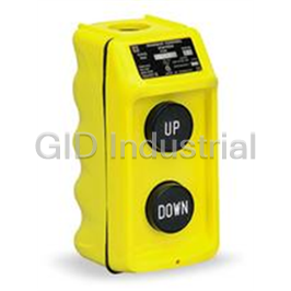
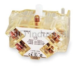
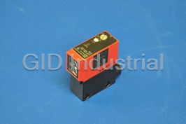

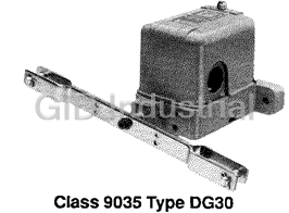


What they say about us
FANTASTIC RESOURCE
One of our top priorities is maintaining our business with precision, and we are constantly looking for affiliates that can help us achieve our goal. With the aid of GID Industrial, our obsolete product management has never been more efficient. They have been a great resource to our company, and have quickly become a go-to supplier on our list!
Bucher Emhart Glass
EXCELLENT SERVICE
With our strict fundamentals and high expectations, we were surprised when we came across GID Industrial and their competitive pricing. When we approached them with our issue, they were incredibly confident in being able to provide us with a seamless solution at the best price for us. GID Industrial quickly understood our needs and provided us with excellent service, as well as fully tested product to ensure what we received would be the right fit for our company.
Fuji
HARD TO FIND A BETTER PROVIDER
Our company provides services to aid in the manufacture of technological products, such as semiconductors and flat panel displays, and often searching for distributors of obsolete product we require can waste time and money. Finding GID Industrial proved to be a great asset to our company, with cost effective solutions and superior knowledge on all of their materials, it’d be hard to find a better provider of obsolete or hard to find products.
Applied Materials
CONSISTENTLY DELIVERS QUALITY SOLUTIONS
Over the years, the equipment used in our company becomes discontinued, but they’re still of great use to us and our customers. Once these products are no longer available through the manufacturer, finding a reliable, quick supplier is a necessity, and luckily for us, GID Industrial has provided the most trustworthy, quality solutions to our obsolete component needs.
Nidec Vamco
TERRIFIC RESOURCE
This company has been a terrific help to us (I work for Trican Well Service) in sourcing the Micron Ram Memory we needed for our Siemens computers. Great service! And great pricing! I know when the product is shipping and when it will arrive, all the way through the ordering process.
Trican Well Service
GO TO SOURCE
When I can't find an obsolete part, I first call GID and they'll come up with my parts every time. Great customer service and follow up as well. Scott emails me from time to time to touch base and see if we're having trouble finding something.....which is often with our 25 yr old equipment.
ConAgra Foods