

 Manufacturers
SEALEVEL SYSTEMS 1104
Description
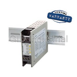
SERIAL I/O - Async Converters, DIN Rail RS-232 to RS-422/485, ports: 1, DIN485+
Part Number
1104
Price
Request Quote
Manufacturer
SEALEVEL SYSTEMS
Lead Time
Request Quote
Category
PRODUCTS - 1
Features
- Summary
Datasheet

Extracted Text
TM DIN485+ USER MANUAL Part # 1104 Sealevel Systems, Inc Phone: (864) 843-4343 155 Technology Place FAX: (864) 843-3067 P.O. Box 830 www.sealevel.com Liberty, SC 29657 USA Contents INTRODUCTION..................................................................................................1 OVERVIEW .............................................................................................................1 WHAT’S INCLUDED ...............................................................................................1 FACTORY DEFAULT SETTINGS ...............................................................................1 CARD SETUP ........................................................................................................2 RS-485 ENABLE MODES ......................................................................................2 LINE TERMINATION AND RECEIVER ECHO OFF/ON ................................................4 ELECTRICAL INTERFACE EXAMPLES (DIP SWITCH SW2).......................................5 OPERATING SYSTEM INSTALLATION (FOR WINDOWS USERS).......6 RS-422/RS-485 Four Wire Master/RS-485 Two Wire Auto Mode Installation .....................................................................................................6 RS-485 Two-Wire and RS-485 Four-Wire Slave Installation.................7 Other Operating Systems .............................................................................8 SYSTEM INSTALLATION..................................................................................9 TECHNICAL DESCRIPTION......................................................................... 10 CONNECTOR PIN ASSIGNMENTS.......................................................................... 10 Power/RS-232 Pin Assignments (6 Position Screw Terminal) ............. 10 RS-422/485 Pin Assignments (6 Position Screw Terminal).................. 10 SPECIFICATIONS ............................................................................................ 11 ENVIRONMENTAL SPECIFICATIONS ..................................................................... 11 MANUFACTURING.............................................................................................. 11 MEAN TIME BETWEEN FAILURES (MTBF)......................................................... 11 PHYSICAL DIMENSIONS ...................................................................................... 11 APPENDIX A - TROUBLESHOOTING........................................................ 12 APPENDIX B - HOW TO GET ASSISTANCE..ERROR! BOOKMARK NOT DEFINED. APPENDIX C - ELECTRICAL INTERFACE .............................................. 14 RS-232.............................................................................................................. 14 RS-422.............................................................................................................. 14 RS-485.............................................................................................................. 15 APPENDIX D - ASYNCHRONOUS COMMUNICATIONS ...................... 16 APPENDIX E - SILK-SCREEN....................................................................... 17 APPENDIX F - COMPLIANCE NOTICES .................................................. 18 FEDERAL COMMUNICATIONS COMMISSION STATEMENT.................................... 18 EMC DIRECTIVE STATEMENT............................................................................ 18 WARRANTY ....................................................................................................... 19 FIGURES Figure 1- Dip switch SW1, RS-422............................................................3 Figure 2 – Dip switch SW1, RS-485 ‘Auto’ Enable ...............................3 Figure 3 – Dip switch SW1, RS-485 ‘RTS’ Enable ................................3 Figure 4 – Dip switch SW1, RS-485 ‘Data’ Enable................................3 Figure 5 – Dip switch SW2, Line Termination and Echo Off/On .......4 Figure 6 – RS-422 with Termination and Receiver Echo ....................5 Figure 7 – RS-485 2-wire with Termination and Receiver No Echo.5 Figure 8 – RS-485 2-wire no Termination and Receiver No Echo.....5 Figure 9 - Asynchronous Communications Bit Diagram ...................16 © 2002a Sealevel Systems, Incorporated. All rights reserved. Introduction Introduction Overview The Sealevel Systems DIN485+ is a single channel RS-232 to RS-422/485 asynchronous converter. It is housed in a Din Rail mount enclosure to simplify installation in an industrial environment. It provides one field selectable RS422/485 serial port supporting asynchronous data rates up to 115.2K bps. The DIN485+ is self-powered allowing it to correctly drive multi-drop RS-485 networks. It requires an input DC supply of 10 (Min.) to 30 (Max.)VDC. This is a voltage range commonly found in an industrial environment i.e. 10VDC, 12VDC, or 24VDC. Configure the port as RS422 for long distance device connections up to 4000ft. where noise immunity and high data integrity are essential. Select RS- 485 and capture data from multiple peripherals in an RS485 multi-drop network. Up to 31 RS-485 devices can be connected to automate your data collection. In RS-422 and RS-485 Auto modes, the card works seamlessly with the standard operating system serial driver. Two additional methods are provided to control the communication line in RS-485 mode. The “Data Enable” mode uses the transmitted data to enable the transmitter and requires no software drivers. This mode has limitations that will be discussed in more detail later. The “RTS Enable” mode uses the UART modem control signal RTS to control the communication line and requires the Sealevel Systems’ serial driver. What’s Included The DIN485+ is shipped with the following items. If any of these items is missing or damaged, contact the supplier. · DIN485+ Serial I/O Adapter · Sealevel Software Factory Default Settings The DIN485+ factory default settings are as follows: Port # Electrical Specification Port 1 RS-422 To install the DIN485+ using factory default settings, refer to Installation. For your reference, record installed DIN485+ settings below: Port # Electrical Specification Port 1 Sealevel Systems DIN485+ Page 1 Card Setup Card Setup RS-485 Enable Modes RS-485 is ideal for multi-drop or network environments. RS-485 requires a tri-state driver that will allow the electrical presence of the driver to be removed from the line. The driver is in a tri-state or high impedance condition when this occurs. Only one driver may be active at a time and the other driver(s) must be tri-stated. The output modem control signal Request To Send (RTS) is typically used to control the state of the driver. Some communication software packages refer to RS-485 as RTS enable or RTS block mode transfer. Dip switch SW1 is used to control the RS-485 mode functions for the driver circuit. The selections are: ‘RS-422 Mode’ (Always). This is the factory default mode that ensures the transmitter is always enabled. This mode is intended for Full Duplex applications such as RS-422 or RS-485 4-wire Master mode where tri-state control of the transmitter is not required. ‘RS-485 Auto Mode’. This mode uses an onboard MicroChip PIC microcontroller to sense the baud rate and control the transmitter enable signal based on the detected baud rate. The logic assumes a minimum baud rate of 1200bps and a word length of 10 bits (1 start bit, 8 data bits, and 1 stop bit). For baud rates of 38.4K or less, line turnaround should not exceed 4 bit times, 57.6K should not exceed 10 bit times, and 115.2K should not exceed 20 bit times after successfully autobauding. ‘RS-485 RTS Enable Mode’. The ‘RTS’ enable mode uses the ‘RTS’ modem control signal to enable the RS-485 interface and provides backward compatibility with existing software products. Sealevel Systems’ serial driver should be used and configured for ‘RTS’ control providing a robust RS-485 solution. ‘RS-485 Data Enable Mode’. The ‘Data’ enable mode uses the transmit data stream to enable/disable the transmitter. When the data bit is High (logic 1), the transmitter will be tri-stated and relies on the line biasing resistors to place the line in the proper state. For this reason, line termination cannot be used thus reducing the data rate and maximum cable length. This mode should only be used in applications that prevent the use of the RS-485 Auto Mode or Sealevel Systems’ serial driver. Sealevel Systems DIN485+ Page 2 Card Setup Communication Mode Examples (Dip switch SW1) OFF ON 1 2 Figure 1- Dip switch SW1, RS-422 OFF ON 1 2 Figure 2 – Dip switch SW1, RS-485 ‘Auto’ Enable OFF ON 1 2 Figure 3 – Dip switch SW1, RS-485 ‘RTS’ Enable OFF ON 1 2 Figure 4 – Dip switch SW1, RS-485 ‘Data’ Enable Sealevel Systems DIN485+ Page 3 Card Setup Line Termination and Receiver Echo Off/On Typically, each end of the RS-485 bus must have a line-terminating resistor (RS-422 terminates at the receive end only). A 120-ohm resistor is across each RS-422/485 input in addition to a 1K-ohm pull-up/pull-down combination that biases the receiver inputs. Dip switch SW2 allows customization of this interface to specific requirements. Each dip switch position corresponds to a specific portion of the interface. If multiple DIN485+ adapters are configured in an RS-485 network, only the adapters on each end should have dip switch SW2 position 1 on. One adapter should have dip switch SW2 positions 2 and 3 on. Refer to the table below for each position’s operation. Dip switch SW2 position 6 is used to control the RS-485 enable/disable functions for the receiver circuit and determines the state of the RS-422/485 driver. The RS-485 ‘Echo’ is the result of connecting the receiver inputs to the transmitter outputs. Every time a character is transmitted, it is also received. This can be beneficial if the software can handle echoing (i.e. using received characters to throttle the transmitter) or it can confuse the system if the software does not. To enable the ‘No Echo’ mode dip switch SW2 position 6 should be on. SW2 Function 1 Adds or removes the 120-ohm termination 2 Adds or removes the 1K-ohm pull-up resistor in the RS-422/RS-485 receiver circuit (Receive data only) 3 Adds or removes the 1K-ohm pull-down resistor in the RS-422/RS- 485 receiver circuit (Receive data only) 4 Connects TX+ to RX+ for RS-485 two-wire operation 5 Connects TX- to RX- for RS-485 two-wire operation 6 Receiver Echo Off/On (On = Echo Off) OFF ON 1 2 3 4 5 6 Figure 5 – Dip switch SW2, Line Termination and Echo Off/On Sealevel Systems DIN485+ Page 4 Card Setup Electrical Interface Examples (Dip switch SW2) Electrical Interface Examples (Dip switch SW2) OFF ON 1 2 3 4 5 6 Figure 6 – RS-422 with Termination and Receiver Echo OFF ON 1 2 3 4 5 6 Figure 7 – RS-485 2-wire with Termination and Receiver No Echo OFF ON 1 2 3 4 5 6 Figure 8 – RS-485 2-wire no Termination and Receiver No Echo Sealevel Systems DIN485+ Page 5 Installation Operating System Installation (For Windows Users) RS-422/RS-485 Four Wire Master/RS-485 Two Wire Auto Mode Installation If your application is 4-wire Full Duplex RS-422 or 4-Wire RS-485 Master, where control of the transmitter is not required, or 2-wire RS-485 and you intend to use the Auto Mode to control the transmitter, simply connect the DIN485+ to an existing RS-232 COM: port. This will utilize the Operating System Serial Driver to control the COM: port. You will want to install Sealevels’ diagnostic utility, WinSSD, to test and verify proper operation of the port. Start by choosing Install Software at the beginning of the CD. Choose Asynchronous COM: Port Software, SeaCOM. Continue with the installation until the “Setup Type” dialog, as shown below, appears. Choose “WinSSD Utility” to install just the diagnostic tool. A Start Menu Program Group, “SeaCOM” will be created and WinSSD can be started from there. Sealevel Systems DIN485+ Page 6 Installation RS-485 Two-Wire and RS-485 Four-Wire Slave Installation If your application is 2-wire Half-Duplex RS-485 or 4-Wire Full-Duplex RS- 485 Slave that requires control of the transmitter, the DIN485+ provides 3 methods of control. The first method is ‘Auto Enable’ which uses an onboard microcontroller to sense the baud rate and control the transmitter enable. This mode assumes a minimum baud rate of 1200bps and a word length of 10 bits. This would be the preferred method, as it requires no software in order to work. This mode should be used with line termination since the transmitter is driving the line during transmission. The second method is ‘RTS Enable’ which uses Sealevels’ Windows based serial drivers to control the UART modem control signal RTS. RTS is connected to the transmitter enable circuit and thru software control, provides an efficient method of line-turnaround. This abstracts the application from the low level control and simplifies application development. This mode should be used with line termination since the transmitter is driving the line during transmission. The last method is ‘Data Enable’ which uses the transmitted data stream to enable the transmitter and requires no special software drivers. When the transmitted data is a low (0), the transmitter will be enabled to drive the line. When the transmitted data is a high (1), the transmitter will be tri-stated relying on the line biasing resistors to pull the line to the proper state. Due to this, termination must not be used and thus data rate and cable length are reduced accordingly. The choice of which method to use is simple. If your data stream permits the use of the ‘Auto Enable’ mode always use this option as it permits the simplest installation. If ‘Auto Enable’ is not an option and you are using the DIN485+ in a Windows based system, setup the transmitter control for ‘RTS Enable’ and install Sealevels’ SeaCOM software. Again, if ‘Auto Enable’ is not an option, and your system is not Windows based or if the port you are converting is not PC based, use ‘Data Enable’. If ‘RTS Enable’ mode is chosen, start by choosing Install Software at the beginning of the CD. Choose Asynchronous COM: Port Software, SeaCOM. Continue with the installation until the “Setup Type” dialog, as shown below, appears. Choose “Typical (complete)” to install the software including drivers and applications. A Start Menu Program Group, “SeaCOM” will be created and WinSSD can be started from there. Sealevel Systems DIN485+ Page 7 Installation Once the software installation is complete, the port must be configured for ‘RTS Enable’. This is accomplished by using the Device Manager in Windows 9X, ME, and Windows 2000. The port that the DIN485+ is attached must be selected under Ports (COM & LPT). Access the ‘RTS Enable’ checkbox via the ‘Advanced’ dialog. In Windows NT, Sealevels’ ‘Advanced Ports’ applet should be used for configuration. Other Operating Systems Linux includes a full featured serial driver that includes support not found in Microsoft’s serial driver. Most serial drivers offer a mechanism to control RTS from the application layer. While this is not as efficient and normally means using ‘Echo’ to know when to turn off the transmitter, for most applications this is adequate. The ‘Auto Enable’ and ‘Data Enable’ modes can also be used. Refer to your operating system documentation for specifics. Sealevel Systems DIN485+ Page 8 Installation System Installation The DIN485+ can be connected to any existing RS-232 port. A cable such as Sealevels’ CA-186 can be used to attach the DIN485+ to the PC’s DB-9M connector. 1. Locate an existing RS-232 COM: port and connect the DIN485+ via the provided 6-position screw terminal. Sealevels’ CA-186 cable can be utilized to connect to an existing D-Sub connector. 2. With the DIN485+ case open, configure dip switches SW1 and SW2 for your application. 3. Connect the wiring to your external device via the provided 6-position screw terminal. 4. Make sure all connections are secure and that strain relief is adequately installed. 5. Close the DIN485+ case and connect a DC supply voltage of 10 to 30VDC. 6. If the DIN485+ is in RS-422 mode, the EN led should now be on since the transmitter is always enabled. Installation is complete. Please Note: On power-up, the DIN485+ scans the Mode Select dip switch (SW1) one time to determine the communication mode and then branches to the selected control logic. No attempt is made to periodically check the switch for a mode change. This is done for two reasons. First, our experience shows that a device such as this is configured for the required application and the mode is not changed after this. Due to this reason, the product is not burdened with the overhead of always checking this switch. At higher baud rates this becomes especially critical due to the speed of the onboard microcontroller. The utmost priority is given to sampling the incoming data. What this means? If the DIN485+ has been configured for a particular mode, and for some reason it has become necessary to change the communication mode, remove power, reconfigure the Mode Select dip switch (SW1) for the new mode, and reapply power. Sealevel Systems DIN485+ Page 9 Technical Description Technical Description The Sealevel Systems DIN485+ converts an existing RS-232 serial port into a field selectable RS-422/485 port for industrial automation and control applications. Connector Pin Assignments Power/RS-232 Pin Assignments (6 Position Screw Terminal) Signal Name Pin # Mode TD Transmit Data 1 Input RD Receive Data 2 Output RT Request to Send 3 Input +V +DC Supply Input 4 Input -DC Supply Input 5 Input Shield 6 Input Note: These assignments meet EIA/TIA/ANSI-232E DTE Technical Note: The modem control signals are biased in the following fashion when using Sealevels’ CA-186 cable: RTS and CTS are connected, DTR is connected to DCD and DSR, and RI is tied inactive. RS-422/485 Pin Assignments (6 Position Screw Terminal) Signal Name Pin # Mode RDB R+ Receive Data Positive 7 Input RDA R- Receive Data Negative 8 Input TDB T+ Transmit Data Positive 9 Output TDA T- Transmit Data Negative 10 Output GND Ground 11 SHIELD Shield 12 Sealevel Systems DIN485+ Page 10 Specifications Specifications Environmental Specifications Specification Operating Storage Temperature 0º to 50º C -20º to 70º C Range (32º to 122º F) (-4º to 158º F) Humidity Range 10 to 90% R.H. 10 to 90% R.H. Non-Condensing Non-Condensing Manufacturing · All Sealevel Systems Printed Circuit boards are built to U. L. 94V0 rating and are 100% electrically tested. These printed circuit boards are solder mask over bare copper or solder mask over tin nickel. Mean Time Between Failures (MTBF) Greater than 150,000 hours. (Calculated) Physical Dimensions Package Depth 4.33 inches (11 cm) Package Width .88 inches (2.25 cm) Package Height 2.95 inches (7.5 cm) Sealevel Systems DIN485+ Page 11 Appendix A - Troubleshooting Appendix A - Troubleshooting Serial Utility test software is supplied with the Sealevel Systems adapter and should be used in the troubleshooting procedures. Using this software and following these simple steps, most common problems can be eliminated without the need to call Technical Support. 1. The DIN485+ is a level converter and therefore requires no system resources such as I/O ports or IRQ’s. The I/O resources of the host RS- 232 COM: port will be used to access the port. 2. If you are experiencing problems, a good starting point is to verify proper operation of the host RS-232 COM: port. Connect the host port TX and RX lines and use Sealevels’ WinSSD utility to perform a loopback test. If you cannot open the host port, ensure that it is enabled in the System BIOS. If using a Plug ‘n’ Play operating system, verify that it is recognized by the system. 3. If the host RS-232 port is working properly, verify that the DIN485+ is configured correctly for your application based on the ‘Card Setup’ section earlier in this manual. After attaching the DIN485+, you may perform a loopback test by connecting TX+ to RX+ and TX- to RX-. Keep in mind that this test will fail should you have dip switch SW2 position 6 on. This forces the DIN485+ into ‘No Echo’ mode and will prevent the loopback test from passing. For loopback purposes, always have dip switch SW2 position 6 off even if you will use No Echo in your actual application. 4. During the loopback test, pay attention to the TX and RX leds as both of these should be on. Failure of one or both of these to be on would indicate a hardware problem on the adapter. Sealevel Systems DIN485+ Page 12 Appendix B - How To Get Assistance Appendix B - How To Get Assistance 1. Begin by reading through the Trouble Shooting Guide in Appendix A. If assistance is still needed please see below. 2. When calling for technical assistance, please have your user manual and current adapter settings. If possible, please have the adapter installed in a computer ready to run diagnostics. 3. Sealevel Systems provides an FAQ section on its web site. Please refer to this for many commonly asked questions. This section can be found at http://www.sealevel.com/faq.htm . 4. Visit Sealevel’s website at www.sealevel.com for the latest software updates and newest manuals. 5. Technical support is available Monday to Friday from 8:00 a.m. to 5:00 p.m. eastern time. Technical support can be reached at (864) 843-4343. RETURN AUTHORIZATION MUST BE OBTAINED FROM SEALEVEL SYSTEMS BEFORE RETURNED MERCHANDISE WILL BE ACCEPTED. AUTHORIZATION CAN BE OBTAINED BY CALLING SEALEVEL SYSTEMS AND REQUESTING A RETURN MERCHANDISE AUTHORIZATION (RMA) NUMBER. Sealevel Systems DIN485+ Page 13 Appendix C – Electrical Interface Appendix C - Electrical Interface RS-232 Quite possibly the most widely used communication standard is RS-232. This implementation has been defined and revised several times and is often referred to as RS-232 or EIA/TIA-232. The IBM PC computer defined the RS-232 port on a 9 pin D sub connector and subsequently the EIA/TIA approved this implementation as the EIA/TIA-574 standard. This standard is defined as the 9-Position Non-Synchronous Interface between Data Terminal Equipment and Data Circuit-Terminating Equipment Employing Serial Binary Data Interchange. Both implementations are in wide spread use and will be referred to as RS-232 in this document. RS-232 is capable of operating at data rates up to 20 Kbps at distances less than 50 ft. The absolute maximum data rate may vary due to line conditions and cable lengths. RS-232 is a single ended or unbalanced interface, meaning that a single electrical signal is compared to a common signal (ground) to determine binary logic states. The RS-232 and the EIA/TIA-574 specification define two types of interface circuits, Data Terminal Equipment (DTE) and Data Circuit-Terminating Equipment (DCE). The DIN485+ is a DCE device. RS-422 The RS-422 specification defines the electrical characteristics of balanced voltage digital interface circuits. RS-422 is a differential interface that defines voltage levels and driver/receiver electrical specifications. On a differential interface, logic levels are defined by the difference in voltage between a pair of outputs or inputs. In contrast, a single ended interface, for example RS-232, defines the logic levels as the difference in voltage between a single signal and a common ground connection. Differential interfaces are typically more immune to noise or voltage spikes that may occur on the communication lines. Differential interfaces also have greater drive capabilities that allow for longer cable lengths. RS-422 is rated up to 10 Megabits per second and can have cabling 4000 feet long. RS-422 also defines driver and receiver electrical characteristics that will allow 1 driver and up to 32 receivers on the line at once. RS-422 signal levels range from 0 to +5 volts. RS-422 does not define a physical connector. Sealevel Systems DIN485+ Page 14 Appendix C – Electrical Interface RS-485 RS-485 is backwardly compatible with RS-422; however, it is optimized for partyline or multi-drop applications. The output of the RS-422/485 driver is capable of being Active (enabled) or Tri-State (disabled). This capability allows multiple ports to be connected in a multi-drop bus and selectively polled. RS-485 allows cable lengths up to 4000 feet and data rates up to 10 Megabits per second. The signal levels for RS-485 are the same as those defined by RS-422. RS-485 has electrical characteristics that allow for 32 drivers and 32 receivers to be connected to one line. This interface is ideal for multi-drop or network environments. RS-485 tri-state driver (not dual-state) will allow the electrical presence of the driver to be removed from the line. Only one driver may be active at a time and the other driver(s) must be tri-stated. RS-485 can be cabled in two ways, two wire and four wire mode. Two wire mode does not allow for full duplex communication, and requires that data be transferred in only one direction at a time. For half-duplex operation, the two transmit pins should be connected to the two receive pins (Tx+ to Rx+ and Tx- to Rx-). Four wire mode allows full duplex data transfers. RS-485 does not define a connector pin-out or a set of modem control signals. RS-485 does not define a physical connector. Sealevel Systems DIN485+ Page 15 Appendix D - Asynchronous Communications Appendix D - Asynchronous Communications Serial data communications implies that individual bits of a character are transmitted consecutively to a receiver that assembles the bits back into a character. Data rate, error checking, handshaking, and character framing (start/stop bits) are pre-defined and must correspond at both the transmitting and receiving ends. Asynchronous communications is the standard means of serial data communication for PC compatibles and PS/2 computers. The original PC was equipped with a communication or COM: port that was designed around an 8250 Universal Asynchronous Receiver Transmitter (UART). This device allows asynchronous serial data to be transferred through a simple and straightforward programming interface. A start bit, followed by a pre-defined number of data bits (5, 6, 7, or 8) defines character boundaries for asynchronous communications. The end of the character is defined by the transmission of a pre-defined number of stop bits (usually 1, 1.5 or 2). An extra bit used for error detection is often appended before the stop bits. Idle state of Odd, Even line or Remain Idle or 5 to 8 Data Bits Unused next start bit 1 P STOP BIT 0 1 1.5 2 Figure 9 - Asynchronous Communications Bit Diagram This special bit is called the parity bit. Parity is a simple method of determining if a data bit has been lost or corrupted during transmission. There are several methods for implementing a parity check to guard against data corruption. Common methods are called (E)ven Parity or (O)dd Parity. Sometimes parity is not used to detect errors on the data stream. This is refereed to as (N)o parity. Because each bit in asynchronous communications is sent consecutively, it is easy to generalize asynchronous communications by stating that each character is wrapped (framed) by pre-defined bits to mark the beginning and end of the serial transmission of the character. The data rate and communication parameters for asynchronous communications have to be the same at both the transmitting and receiving ends. The communication parameters are baud rate, parity, number of data bits per character, and stop bits (i.e. 9600, N, 8, 1). Sealevel Systems DIN485+ Page 16 Appendix E - Silk-Screen Appendix E - Silk-Screen 2.828 in Sealevel Systems DIN485+ Page 17 3.938 in Appendix F - Compliance Notices Appendix F - Compliance Notices Federal Communications Commission Statement FCC - This equipment has been tested and found to comply with the limits for Class A digital device, pursuant to Part 15 of the FCC Rules. These limits are designed to provide reasonable protection against harmful interference when the equipment is operated in a commercial environment. This equipment generates, uses, and can radiate radio frequency energy and, if not installed and used in accordance with the instruction manual, may cause harmful interference to radio communications. Operation of this equipment in a residential area is likely to cause harmful interference in such case the user will be required to correct the interference at his own expense. EMC Directive Statement Products bearing the CE Label fulfill the requirements of the EMC directive (89/336/EEC) and of the low-voltage directive (73/23/EEC) issued by the European Commission. To obey these directives, the following European standards must be met: • EN55022 Class A - “Limits and methods of measurement of radio interference characteristics of information technology equipment” • EN55024 -'Information technology equipment Immunity characteristics Limits and methods of measurement' • EN60950 (IEC950) - “Safety of information technology equipment, including electrical business equipment” Warning This is a Class A Product. In a domestic environment this product may cause radio interference in which case the user may be required to take adequate measures. Always use cabling provided with this product if possible. If no cable is provided or if an alternate cable is required, use high quality shielded cabling to maintain compliance with FCC/EMC directives. Sealevel Systems DIN485+ Page 18 Warranty Warranty Sealevel Systems, Inc. provides a lifetime warranty for this product. Should this product fail to be in good working order at any time during this period, Sealevel Systems will, at it's option, replace or repair it at no additional charge except as set forth in the following terms. This warranty does not apply to products damaged by misuse, modifications, accident or disaster. Sealevel Systems assumes no liability for any damages, lost profits, lost savings or any other incidental or consequential damage resulting from the use, misuse of, or inability to use this product. Sealevel Systems will not be liable for any claim made by any other related party. RETURN AUTHORIZATION MUST BE OBTAINED FROM SEALEVEL SYSTEMS BEFORE RETURNED MERCHANDISE WILL BE ACCEPTED. AUTHORIZATION CAN BE OBTAINED BY CALLING SEALEVEL SYSTEMS AND REQUESTING A RETURN MERCHANDISE AUTHORIZATION (RMA) NUMBER. Sealevel Systems, Incorporated 155 Technology Place P.O. Box 830 Liberty, SC 29657 USA (864) 843-4343 FAX: (864) 843-3067 www.sealevel.com email: support@sealevel.com Technical Support is available from 8 a.m. to 5 p.m. Eastern time. Monday - Friday Trademarks Sealevel Systems, Incorporated acknowledges that all trademarks referenced in this manual are the service mark, trademark, or registered trademark of the respective company. DIN485+ is a trademark of Sealevel Systems, Incorporated. Sealevel Systems DIN485+ Page 19
Frequently asked questions
What makes Elite.Parts unique?

What kind of warranty will the 1104 have?
Which carriers does Elite.Parts work with?
Will Elite.Parts sell to me even though I live outside the USA?
I have a preferred payment method. Will Elite.Parts accept it?


What they say about us
FANTASTIC RESOURCE
One of our top priorities is maintaining our business with precision, and we are constantly looking for affiliates that can help us achieve our goal. With the aid of GID Industrial, our obsolete product management has never been more efficient. They have been a great resource to our company, and have quickly become a go-to supplier on our list!
Bucher Emhart Glass
EXCELLENT SERVICE
With our strict fundamentals and high expectations, we were surprised when we came across GID Industrial and their competitive pricing. When we approached them with our issue, they were incredibly confident in being able to provide us with a seamless solution at the best price for us. GID Industrial quickly understood our needs and provided us with excellent service, as well as fully tested product to ensure what we received would be the right fit for our company.
Fuji
HARD TO FIND A BETTER PROVIDER
Our company provides services to aid in the manufacture of technological products, such as semiconductors and flat panel displays, and often searching for distributors of obsolete product we require can waste time and money. Finding GID Industrial proved to be a great asset to our company, with cost effective solutions and superior knowledge on all of their materials, it’d be hard to find a better provider of obsolete or hard to find products.
Applied Materials
CONSISTENTLY DELIVERS QUALITY SOLUTIONS
Over the years, the equipment used in our company becomes discontinued, but they’re still of great use to us and our customers. Once these products are no longer available through the manufacturer, finding a reliable, quick supplier is a necessity, and luckily for us, GID Industrial has provided the most trustworthy, quality solutions to our obsolete component needs.
Nidec Vamco
TERRIFIC RESOURCE
This company has been a terrific help to us (I work for Trican Well Service) in sourcing the Micron Ram Memory we needed for our Siemens computers. Great service! And great pricing! I know when the product is shipping and when it will arrive, all the way through the ordering process.
Trican Well Service
GO TO SOURCE
When I can't find an obsolete part, I first call GID and they'll come up with my parts every time. Great customer service and follow up as well. Scott emails me from time to time to touch base and see if we're having trouble finding something.....which is often with our 25 yr old equipment.
ConAgra Foods