

 Manufacturers
RED LION CONTROLS LNXC2000
Description
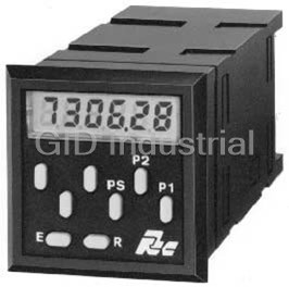
Red Lion Controls LNXC2000 Counter Dual Preset 115VAC Lynx Series
Part Number
LNXC2000
Price
Request Quote
Manufacturer
RED LION CONTROLS
Lead Time
Request Quote
Category
INPUT COUNTER
Specifications
AC Power Versions
115 VAC (±10%), 50/60 Hz, 6 VA. 230 VAC (±10%), 50/60 Hz, 6 VA.
DC Power Versions
11 to 14 VDC @ 180 mA. 21.5 to 30 VDC @ 180 mA.
Display
6-digit, 0.3" (7.6 mm) high LCD display.
Operating Temperature
0 to 50°C
Sensor Power
+12 VDC (±25%) @ 100 mA.
Storage Temperature
-40 to 70°C
Features
- 0.3" (7.6 mm) High, 6 Digit Display
- Ability To Lock Out Front Panel Functions
- Accepts Input Count Rates Up To 15 KHz (Single preset)
- Available In AC or DC Versions
- Bi-Directional Counting
- Display Scrolling (Selectable)
- Form C Relay Output(S)
- Front Panel Programmable Decimal Point
- Non-Volatile Memory (E2PROM)
- Prescale Capability With Disable Switch (Dual Preset)
- Programmable Timed Output(S)
- Remote Reset Capability
- Sealed Front Panel Construction (NEMA 4X/IP65)
- Solid-State Current Sinking Output(S)
Datasheet

Extracted Text
Bulletin No. LNXC1/2-D Drawing No. LP0289 Released 5/03 Tel +1 (717) 767-6511 Fax +1 (717) 764-0839 www.redlion-controls.com MODEL LNXC1 SINGLE PRESET COUNTER MODEL LNXC2 DUAL PRESET COUNTER � 0.3" (7.6 mm) HIGH, 6 DIGIT DISPLAY 2 � NON-VOLATILE MEMORY (E PROM) � DISPLAY SCROLLING (SELECTABLE) � BI-DIRECTIONAL COUNTING � PRESCALE CAPABILITY WITH DISABLE SWITCH (Dual Preset) � FORM C RELAY OUTPUT(S) � SOLID-STATE CURRENT SINKING OUTPUT(S) � PROGRAMMABLE TIMED OUTPUT(S) � REMOTE RESET CAPABILITY � ABILITY TO LOCK OUT FRONT PANEL FUNCTIONS � ACCEPTS INPUT COUNT RATES UP TO 15 KHz (Single preset) � AVAILABLE IN AC OR DC VERSIONS � FRONT PANEL PROGRAMMABLE DECIMAL POINT � SEALED FRONT PANEL CONSTRUCTION (NEMA 4X/IP65) DESCRIPTION SAFETY SUMMARY The Lynx Series of presettable counters is an economical and reliable All safety related regulations, local codes and instructions that appear in the solution to single or dual preset level requirements. The Model LNXC1 is the manual or on equipment must be observed to ensure personal safety and to single preset version and the Model LNXC2 is the dual preset version. Both prevent damage to either the instrument or equipment connected to it. If units have a solid-state output and a Form C relay output for each preset. These equipment is used in a manner not specified by the manufacturer, the protection units feature selectable input configurations, a full compliment of control provided by the equipment may be impaired. inputs, programmable timed outputs, prescale capability with disable switch Do not use this unit to directly command motors, valves, or other actuators (dual preset only), non-volatile memory, and many other features which will not equipped with safeguards. To do so, can be potentially harmful to persons satisfy most any single or dual preset application. or equipment in the event of a fault to the unit. The Lynx Counters have two main counting actions, Reset to Zero (RTZ) and Reset to Preset (RTP). There are eight modes of operation for the single preset SPECIFICATIONS unit and sixteen for the dual preset unit. 1. DISPLAY: 6-digit, 0.3" (7.6 mm) high LCD display. All parameters are programmed through the front panel buttons. The Lynx 2. POWER REQUIREMENTS: counters have an internal non-volatile memory device which eliminates the AC Power Versions: 115 VAC (±10%), 50/60 Hz, 6 VA need for battery back-up. When power is removed, this device will maintain all 230 VAC (±10%), 50/60 Hz, 6 VA data set-ups necessary for system operation. A Program Disable terminal is DC Power Versions: 11 to 14 VDC @ 180 mA. provided, which can be used to prevent accidental changes or tampering by 21.5 to 30 VDC @ 180 mA. unauthorized personnel to the preset(s), prescale or timed output values. The 3. SENSOR POWER: +12 VDC (±25%) @ 100 mA. front panel reset button can also be enabled or disabled by a rear panel DIP 4. COUNT INPUT: DIP switch selectable to accept count pulses from a variety switch. These counters also have an on-line self-test, which can be run at any of sources, including switch contacts, outputs from CMOS or TTL circuits, time without missing counts or missing a preset value. and all standard RLC sensors. Power, input, and output connections are made via removable terminal blocks Current Sourcing: Unit provides 3.9 KΩ pull-down load for sensors with at the rear of the unit. The Lynx Series of counters have a sealed high impact current sourcing outputs. (Max. input voltage, 28 VDC @ 7 mA.) plastic bezel and meet NEMA 4X/IP65 specifications for wash-down and/or Current Sinking: Unit provides 7.8 KΩ pull-up to +12 VDC for sensors dust, when properly installed. with current sinking outputs. (Max. sensor current, 1.6 mA.) Debounce: Damping capacitor provided for switch contact debounce. Limits count speed to 100 cps max. with 50% duty cycle. Lo Bias: Input Trigger levels V = 1.5 V, V = 3.75 V IL IH Hi Bias: Input Trigger levels V = 5.5 V, V = 7.5 V IL IH Note: Bias levels ±10% @ 12 VDC sensor voltage. These levels vary CAUTION: Read complete instructions prior CAUTION: Risk of electric shock. proportionally with the sensor supply voltage. to installation and operation of the unit. 5. PRESCALE VALUE RANGE: 0.00001 to 9.99999 (dual preset unit only). Note: Recommended minimum clearance (behind the panel) for mounting clip installation is 2.7" (68.6)H x 4.0" (101.6)W. DIMENSIONS In inches (mm) PANEL CUT-OUT 1 12. CERTIFICATIONS AND COMPLIANCES: SPECIFICATIONS (Cont’d) SAFETY 6. MAXIMUM COUNT RATES: IEC 1010-1, EN 61010-1: Safety requirements for electrical equipment High Frequency: For the single preset unit only - 15 KHz max. square wave for measurement, control, and laboratory use, Part 1. input for all electronic sensors, under all modes of operation. For dual IP65 Enclosure rating (Face only), IEC 529 preset units, the following chart lists the count rates for all the possible Type 4X Enclosure rating (Face only), UL50 prescale values. ELECTROMAGNETIC COMPATIBILITY DUAL PRESET UNITS ONLY Immunity to EN 50082-2 Prescale Value Frequency Electrostatic discharge EN 61000-4-2 Level 2; 4 Kv contact 0.00001 to 1 12 KHz Level 3; 8 Kv air 1.00001 to 2 9 KHz Electromagnetic RF fields EN 61000-4-3 Level 3; 10 V/m 2.00001 to 3 7 KHz 80 MHz - 1 GHz 3.00001 to 4 5.5 KHz 2 Fast transients (burst) EN 61000-4-4 Level 4; 2 Kv I/O 4.00001 to 5 4.5 KHz 1 Level 3; 2 Kv power 5.00001 to 6 4 KHz 1 RF conducted interference EN 61000-4-6 Level 3; 10 V/rms 6.00001 to 7 3.5 KHz 150 KHz - 80 MHz 7.00001 to 8 3 KHz Emissions to EN 50081-2 8.00001 to 9 3 KHz RF interference EN 55011 Enclosure class A 9.00001 to 9.99999 2.5 KHz Power mains class A Note: For prescale values greater than 7, the timed delay output is affected Notes: by the count speed (rate). 1. Power lines had an external EMI line filter (RLC #LFIL0000 or Low Frequency: both single and dual preset units - 100 Hz for switch equivalent) installed. contact closures. Note: These units will operate with VCM (E through H) 2. I/O cables routed in metal conduit connected to earth ground. modules. 7. CONTROL INPUTS: Active low (V = 0.5 V max.), internally pulled up IL Refer to the EMC Installation Guidelines section of the bulletin for to 5 VDC through a 10 KΩ resistor (I = 0.5 mA). SNK additional information. Remote Reset: Response time = 10 msec. A low will reset the unit and 13. CONSTRUCTION: Black plastic front bezel with black plastic insert. deactivate outputs. Front panel meets NEMA 4X/IP65 requirements for wash-down and dusty Program Disable: A low will inhibit the changing of presets, prescale, and environments, when properly installed. Installation Category II, Pollution timed outputs, as well as testing outputs in self-test. Degree 2. (Panel gasket, mounting clip, nut fasteners, and screws included Up/Down Control: Response time = 150 µsec. A low will cause the unit to with unit.) count down. A high will cause the unit to count up. 14. WEIGHT: 0.8 lbs (0.36 kg). 8. OUTPUTS: Solid-State: Current sinking NPN Open Collector Transistors. FRONT PANEL FUNCTION DESCRIPTION I = 100 mA max., V = 30 VDC max., V = 1 V @ 100 mA. SNK OH OL The units employ eight front panel buttons for control and data entry. The Relay: Form C contacts max. rating 5 amps @ 120/240 VAC, 28 VDC button functions are as described below: (resistive load), 1/8 H.P. @ 120 VAC (inductive load). The operate time is RESET “R”: Resets the counter to either zero or preset, depending on the 5 msec. nominal and the release time is 3 msec. nominal. mode of operation selected. For this button to operate, the enable/disable Relay Life Expectancy - 100,000 cycles at max. rating. (As load level reset switch at the rear of the unit must be set to the enable (EN.) position. decreases, life expectancy increases.) The reset button is also used in conjunction with the preset button(s), to view Programmable Timed Output: The timed output can be programmed from and change the timed output value(s). When reset is activated, all processes 0.01 sec. to 99.99 sec., ±0.1% + 10 msec. The timed output is set for 0.1 are stopped or interrupted (i.e. outputs turn off, display is reset, etc.). This is sec. at the factory. the case under any mode of operation, in any data entry mode. 2 9. MEMORY RETENTION: Non-volatile E PROM retains all programmed PRESET “P1” (“P2”): Labeled P1 and P2 (single preset units only have the information when power is removed or interrupted. P1 preset button). 10. INPUT, POWER, AND OUTPUT CONNECTIONS: Removable The preset 1 value is displayed when the P1 button is pressed, and the Preset terminal blocks. Value mode is accessed (See Program Preset Value). The value remains 11. ENVIRONMENTAL CONDITIONS: displayed for approximately 10 seconds after the button is released. The Operating Temperature: 0 to 50°C preset buttons are also used, in conjunction with the reset button, to view and Storage Temperature: -40 to 70°C change the timed output values (See Program Timed Output Value section.) Operating and Storage Humidity: 85% max. relative humidity ENTER “E”: Used when programming the Preset Value or the Timed Output (non-condensing) from 0°C to 50°C. Value. After the desired value is obtained on the display, pressing the E Altitude: Up to 2000 meters 2 button enters the value into the unit’s internal memory and takes effect 2. Never run Signal or Control cables in the same conduit or raceway with AC immediately. Also the “E” button can be used to exit self-test. power lines, conductors feeding motors, solenoids, SCR controls, and PRESCALE “PS”: Available only on a dual preset unit. When the “PS” button heaters, etc. The cables should be run in metal conduit that is properly is pressed, the prescale value can be programmed (See Program Prescale grounded. This is especially useful in applications where cable runs are long Value). This value remains displayed for approximately 10 seconds after the and portable two-way radios are used in close proximity or if the installation button is released. is near a commercial radio transmitter. 3. Signal or Control cables within an enclosure should be routed as far away as possible from contactors, control relays, transformers, and other noisy INPUT CONFIGURATION & FRONT PANEL components. RESET, DIP SWITCH SET-UP 4. In extremely high EMI environments, the use of external EMI suppression The DIP switches are located at the rear of the unit. DIP switches 1 to 3 devices, such as ferrite suppression cores, is effective. Install them on Signal configure the type of input signal, and DIP switch 4 enables or disables the front and Control cables as close to the unit as possible. Loop the cable through the panel reset button. Refer to the block diagram of the unit for the details of count core several times or use multiple cores on each cable for additional protection. and control circuitry. Install line filters on the power input cable to the unit to suppress power line interference. Install them near the power entry point of the enclosure. The following EMI suppression devices (or equivalent) are recommended: Ferrite Suppression Cores for signal and control cables: Fair-Rite # 0443167251 (RLC #FCOR0000) TDK # ZCAT3035-1330A Steward #28B2029-0A0 Line Filters for input power cables: Schaffner # FN610-1/07 (RLC #LFIL0000) Schaffner # FN670-1.8/07 Corcom #1VR3 Note: Reference manufacturer’s instructions when installing a line filter. 5. Long cable runs are more susceptible to EMI pickup than short cable runs. Therefore, keep cable runs as short as possible. 6. Switching of inductive loads produces high EMI. Use of snubbers across inductive loads suppresses EMI. Snubbers: RLC #SNUB0000 SWITCH SET-UP S1 - SNK.: Provides a 7.8 KΩ pull-up resistor for sensors with sinking outputs. WIRING CONNECTIONS SRC.: Provides a 3.9 KΩ pull-down resistor for sensors with sourcing All conductors should meet voltage and current ratings for each terminal. outputs. Also cabling should conform to appropriate standards of good installation, local S2 - HI FRQ.: Removes damping capacitor and allows operation up to the codes and regulations. It is recommended that power supplied to the unit (AC maximum frequency (See max count rates in specifications). or DC) be protected by a fuse or circuit breaker. LO FRQ.: Connects damping capacitor for switch contact de-bounce. When wiring the unit, remove the terminal block and use the numbers on the Limits count speed to 100 cps. Minimum count ON/OFF times - 5 label to identify the position number with the proper function. Strip the wire, msec. leaving approximately 1/4" bare wire exposed (stranded wires should be tinned S3 - HI BIAS: Sets input trigger levels at mid-range, to accept outputs from 2- with solder). Insert the wire into the terminal and tighten down the screw until the wire proximity sensors, resistive photo-cells, and logic pulses with wire is clamped tightly. Each terminal can accept up to one #14 AWG, two #18 full 0 to +12 V swings. (V = 5.5 V, V = 7.5 V). IL IH AWG or four #20 AWG wire(s). After the terminal block is wired, install it into LO BIAS: Sets input trigger levels to the low range, to accept logic pulses the proper location on the PC board. Wire each terminal block in this manner. with 0 to +5 V swings. (V = 1.5 V, V = 3.75 V). IL IH Caution: Terminal blocks should NOT be removed with power applied to the unit. S4 - DIS.RST.: Disables front panel reset. EN. RST.: Enables front panel reset. INPUT CONNECTIONS Input connections are made on POWER-UP DIAGNOSTICS terminal block TBA, refer to numbers Upon applying power, the Lynx counters perform an internal self-diagnostic on the label to identify the position test of all the stored data. If the tests do not agree, a “P” appears on the right side number with the proper function. of the display. Normal operation of the unit will continue while the “P” is (The input connections are the same displayed. Press the “E” button to remove the “P” and check all data set-up for single or dual preset counters.) values to be certain they are correct. The use of shielded cable is recommended. Follow the EMC EMC INSTALLATION GUIDELINES Installation Guidelines for shield Although this unit is designed with a high degree of immunity to connection. ElectroMagnetic Interference (EMI), proper installation and wiring methods Terminal 1 - “REM.RST.” (remote must be followed to ensure compatibility in each application. The type of the reset) When connected to common electrical noise, source or coupling method into the unit may be different for a manual reset is performed. The various installations. The unit becomes more immune to EMI with fewer I/O output(s) turn off (if activated) and connections. Cable length, routing and shield termination are very important the count display is reset. As long and can mean the difference between a successful installation or a troublesome as this terminal is low, the unit is installation. Listed below are some EMC guidelines for successful installation held at reset. in an industrial environment. Terminal 2 - “PGM.DIS.” (program disable) When this terminal is not connected to common, the following values can be programmed using the 1. Use shielded (screened) cables for all Signal and Control inputs. The shield front panel buttons: (screen) pigtail connection should be made as short as possible. The Preset Value(s) connection point for the shield depends somewhat upon the application. Prescale Value (if S9 is UP) Listed below are the recommended methods of connecting the shield, in order Decimal Point Position of their effectiveness. Timed Output Value(s) a. Connect the shield only at the panel where the unit is mounted to earth Outputs can also be tested during self-test under this condition (See Self-Test ground (protective earth). description for further details). When connected to common, changing these b. Connect the shield to earth ground at both ends of the cable, usually when the noise source frequency is above 1 MHz. values and testing the outputs is no longer possible. c. Connect the shield to common of the unit and leave the other end of the Terminal 3 - “UP/DN” (count direction control) When this terminal is not shield unconnected and insulated from earth ground. connected to common, the count direction is “UP”. When connected to common, the count direction is “DOWN”. 3 SECOND: Once the preset value is displayed, a specific digit can be INPUT CONNECTIONS (Cont’d) incremented by pressing the button directly beneath that digit. Pressing and Terminal 4 - “CNT.IN” (count input) When the signal is pulled low, a count holding the button down will continuously scroll the digit from 0 through 9, will be registered. (See Count Input and Count Rates under the Specifications then back to 0 again. When the desired value for that digit is reached, release Section.) the button. Repeat this step until the desired preset value is obtained. Terminal 5 - “COMM.” (common) Is the common line to which the sensor and THIRD: Press the “E” button to enter the value into the unit’s memory. As other input commons are connected. (Do NOT connect relay commons or Soon As the “E” button is pressed, the new preset value takes effect. If the solid-state output commons to this point.) “E” button is not pressed within 10 seconds, the unit returns to normal Terminal 6 - “DC OUT” (+12 V) This is for sensor supply and can provide up display operation with the previous value retained. to 100 mA of current. POWER & OUTPUT CONNECTIONS PROGRAM TIMED OUTPUT VALUE * The input power and relay output connections are made to the bottom The factory default Timed Output Value is 0.10 seconds, but can be terminal block (TBB), and the solid-state outputs are connected to the polarized programmed from 0.01 to 99.99 seconds. To enter a different value, the operator must enter the Timed Output Value Programming Mode by performing the three-pin connector. following steps. AC POWER WIRING Note: During the displaying, changing, and entering of a new timed output Primary AC power is connected to terminals 1 and 2 of TBB (marked VAC value, all functions of the unit are operational (i.e. counting, resetting, 50/60 Hz). To reduce the chance of noise spikes entering the AC line and outputs activating, etc.) affecting the unit, the power should be relatively “clean” and within the 10% FIRST: Set S4 Reset “EN./DIS.” switch to the “Enable” position. variation limit. Drawing power from heavily loaded circuits, or from circuits SECOND: Press and hold the “P1”, or “P2” button if a dual preset unit, and that also power loads that cycle on and off(contactors, relays, motors, then press the “R” button. The respective timed output value is displayed and machinery, etc.), should be avoided. remains displayed for approximately 10 seconds after release of the button. At this time, the timed output display mode can be exited, without change, by DC POWER WIRING pressing the “E” button. The DC power is connected to terminals 1 and 2 of TBB. The DC plus(+) THIRD: Once the timed output value is displayed, a specific digit can be power is connected to TBB 1 and the minus(-) is connected to TBB 2. incremented by pressing the button directly beneath that digit. Pressing and OUTPUT WIRING holding the button down will continuously scroll the digit from 0 through 9, Terminals 3, 4, and 5 of TBB are used to connect to output relay 1. Terminals then back to 0 again. When the desired value for that digit is reached, release 6, 7, and 8 of TBB (dual preset only) are used to connect to output relay 2 (Refer the button. Repeat this step until the desired timed output value is obtained. to block diagram). FOURTH: Press the “E” button to enter the value into the unit’s memory. As The solid-state output connector has three wires (two wires for the single Soon As the “E” button is pressed, the new timed output value takes effect. preset unit) for connections. If the “E” button is not pressed within 10 seconds, the unit returns to normal display operation with the previous value retained. Yellow wire - Solid-state output 1 (labeled 01 SNK.) internally connects to an NPN Open Collector transistor. PROGRAM PRESCALE VALUE * (Dual Preset Only) Black wire - common for the solid-state output(s). This terminal should NOT The factory default Prescale Value is 1.00000. To enter a different value, the be used as the common for the input or control terminals. operator must enter the Prescale Value Programming Mode by performing the Blue wire (dual preset only) - Solid-state output 2 (labeled 02 SNK.). following steps. internally connects to an NPN Open Collector transistor. Note: During the displaying, changing, and entering of a new prescale value, Relay Connections all functions of the unit are operational (i.e. counting, resetting, outputs To prolong contact life and suppress electrical noise interference due to the activating, etc.) switching of inductive loads, it is good installation practice to install a snubber FIRST: Set S9 Prescale “EN./DIS.” switch to the “Enable” position. across the contactor. Follow the manufacturer’s instructions for installation. SECOND: Press the “PS” button. This displays the prescale value which Note: Snubber leakage current can cause some electro-mechanical devices to be remains displayed for approximately 10 seconds after release of the button. held ON. At this time, the prescale mode can be exited without change by pressing the “E” button. DISPLAY SCROLLING THIRD: Once the prescale value is displayed, a specific digit can be To set the display to scroll, press and hold the “E” button and then press the incremented by pressing the button directly beneath that digit. Pressing and left- most button on the front panel. To stop the scrolling, repeat the above step. holding the button down will continuously scroll the digit from 0 through 9, DISPLAY SCROLLING SEQUENCE then back to 0 again. When the desired value for that digit is reached, release Single Preset Dual Preset the button. Repeat this step until the desired prescale value is obtained. P1 P1 Value of P1 Value of P1 FOURTH: Press the “E” (Enter) button to enter the value into the unit’s Count Value P2 memory. As Soon As the “E” button is pressed, the new prescale value takes Value of P2 effect. If the “E” button is not pressed within 10 seconds, the unit returns to Count Value normal display operation with the previous value retained. FIFTH: Return S9 to the “Disable” position if desired. PRESCALE ENABLE/DISABLE SWITCH (Dual Preset Only) PROGRAM DECIMAL POINT * The Dual Preset Lynx Counters have an extra switch next to the four mode The Lynx has the capability of displaying a decimal point in one of five DIP switches which is labeled “PS. EN./DIS.” (S9). When this switch is in the positions. The decimal point selection can be done at any time without missing enable position (UP), the prescale value can be changed (See Program Prescale counts or preset outputs. The factory default for the Decimal Point Position is Value). When this switch is in the disable position (DOWN), the prescale value none. To turn a decimal point on, the operator must enter the Decimal Point cannot be changed. Selection Mode by performing the following steps. The prescale value cannot be changed if Program Disable is activated even Note: During the displaying, changing, and entering of a new decimal point though the “PS. EN./DIS.” switch is in the Enable position. value, all functions of the unit are operational (i.e. counting, resetting, outputs activating) PROGRAM PRESET VALUE * FIRST: Press and release the left- most button on the front panel. This places The factory default values are set to 500 for preset 1 and 1,000 for preset 2. the Lynx in the decimal point select mode. To enter a different value, the operator must enter the Preset Value Programming SECOND: Press the digit button which corresponds to the desired decimal Mode by performing the following steps. point position. A decimal point will appear to the right of the digit selected. Note: During the displaying, changing, and entering of a new preset value, all If the right- most digit button (P1) is selected, the decimal point is turned off. functions of the unit are operational (i.e. counting, resetting, outputs THIRD: At the time the decimal point is selected, the unit automatically returns activating, etc.) to normal operation. No further action is required by the operator. FIRST: Press “P1”, (or “P2” if a dual preset unit). This displays the respective - To enter any new data into the Lynx, the “PGM.DIS.” terminal must * preset value, which remains displayed for approximately 10 seconds after not be connected to common. release of the button. At this time, the preset display mode can be exited, without change, by pressing the “E” button. 4 MODES OF OPERATION, DIP SWITCH SET-UP The DIP switches for the various operating modes are located on the side of front panel reset (if enabled) or remote reset overrides any condition or state the unit. For Reset to Zero modes, the UP/DN terminal is normally NOT of the counter and begins the cycle again. connected to common (count up). For Reset to Preset modes, the UP/DN Note: In modes four and twelve (Single preset) and in modes four, five, twelve, terminal is normally connected to common (count down). The unit will maintain and thirteen (Dual preset) the output may appear to be latched if the time normal operating functions if the direction is reversed. delay is longer than the time required to count from the reset condition to the Note: During automatic reset, no counts will be missed if the count rate does not preset point. exceed the maximum count rate specified. A manual reset, either from the MODES OF OPERATION FOR SINGLE PRESET LYNX COUNTER MODE 0 LATCH OUTPUT AT PRESET, MANUAL RESET TO ZERO MODE 8 LATCH OUTPUT AT ZERO, MANUAL RESET TO PRESET ✝ The unit counts from zero, when the preset value is reached, The unit counts from preset, when zero is reached the output the output turns on and counts continue to accumulate. When turns on and counts continue to accumulate . When a manual a manual reset is performed, the count resets to zero and the reset is performed, the unit resets to preset, the output turns off, output turns off. and the cycle starts again. MODE 1 TIMED OUTPUT AT PRESET, MANUAL RESET TO ZERO MODE 9 TIMED OUTPUT AT ZERO, MANUAL RESET TO PRESET ✝ The unit counts from zero, when the preset is reached the The unit counts from preset, when zero is reached, the output turns on for the amount of time programmed and output turns on for the amount of time programmed and counts counts continue to accumulate. When a manual reset is continue to accumulate. When a manual reset is performed, the performed, the unit resets to zero and starts the cycle again. unit resets to preset and starts the cycle again. MODE 2 & 3 - MODE 10 & 11 - * * MODE 4 TIMED OUTPUT AT PRESET, AUTOMATIC RESET TO ZERO AT PRESET MODE 12 TIMED OUTPUT AT ZERO, AUTOMATIC RESET TO PRESET AT ZERO ✝ The unit counts from zero, when the preset is reached, the The unit counts from preset, when zero is reached, the output turns on for the amount of time programmed. At preset, output turns on for the amount of time programmed. At zero, the unit automatically resets to zero and starts the counting the unit automatically resets to preset and starts the counting cycle over again. cycle again. MODE 5 - MODE 13 - * * MODE 6 TIMED OUTPUT AT PRESET, AUTOMATIC RESET TO ZERO AFTER THE MODE 14 TIMED OUTPUT AT ZERO, AUTOMATIC RESET TO PRESET AFTER THE TIMED OUTPUT TIMED OUTPUT✝ The unit counts from zero, when the preset is reached the The unit counts from preset, when zero is reached, the output turns on for the amount of time programmed. At the output turns on for the amount of time programmed. At the end end of the timed output, the unit automatically resets to zero of the timed output, the unit automatically resets to preset and and starts the cycle over again. starts the cycle over. MODE 7 - MODE 15 - * * - These modes are not applicable to the single preset Lynx counter (they are ✝ - When down count is desired, (such as reset to preset modes of operation) * used only for the dual preset counter unit). the “UP/DN” terminal must be tied to the “COMM.” terminal. MODES OF OPERATION FOR DUAL PRESET LYNX COUNTER MODE 0 LATCH OUTPUTS AT PRESET, MANUAL RESET TO ZERO MODE 4 OUTPUT 1 TURN OFF AT PRESET 2, TIMED OUTPUT 2 AT PRESET 2, AUTOMATIC RESET TO ZERO AT PRESET 2 The unit counts from zero, when preset 1 is reached, The unit counts from zero, when preset 1 is reached, output 1 turns on and counts continue to accumulate. When output 1 turns on. When preset 2 is reached, output 2 turns preset 2 is reached, output 2 turns on and counts continue to on for the amount of time programmed. At the beginning of accumulate. When a manual reset is performed, the count resets to zero and timed output 2, output 1 turns off and the unit automatically resets to zero. the outputs turn off. MODE 5 TIMED OUTPUTS AT PRESETS, AUTOMATIC RESET TO ZERO AT PRESET 2 MODE 1 TIMED OUTPUTS AT PRESET, MANUAL RESET TO ZERO The unit counts from zero, when preset 1 is reached, The unit counts from zero, when preset 1 is reached, output 1 turns on, and when preset 2 is reached, output 2 output 1 turns on. When preset 2 is reached, output 2 turns turns on. The outputs turn off at the end of their respective on. Counts continue to accumulate after the preset levels programmed time values. At preset 2, the count automatically resets to zero have been reached. The outputs turn off after their respective programmed and starts the cycle again. time values. When a manual reset is performed, the unit resets to zero and starts the cycle again. MODE 6 OUTPUT 1 TURN OFF AT PRESET 2, TIMED OUTPUT 2 AT PRESET 2, AUTOMATIC RESET TO ZERO AFTER TIMED OUTPUT 2 MODE 2 OUTPUT 1 TURN OFF AT PRESET 2, LATCH OUTPUT 2 AT PRESET 2, The unit counts from zero, when preset 1 is reached, MANUAL RESET TO ZERO output 1 turns on. When preset 2 is reached, output 2 turns The unit counts from zero, when preset 1 is reached, on for the amount of time programmed and output 1 turns output 1 turns on. When preset 2 is reached, output 2 turns off. At the end of timed output 2, the count automatically resets to zero and on and output 1 turns off. Counts continue to accumulate starts the cycle again. after the preset levels have been reached. Output 2 remains on until a manual reset occurs. Manual reset turns off both outputs and the count resets to zero. MODE 7 TIMED OUTPUTS AT PRESETS, AUTOMATIC RESET TO ZERO AFTER TIMED OUTPUT 2 MODE 3 OUTPUT 1 TURN OFF AT PRESET 2, TIMED OUTPUT 2 AT PRESET 2, The unit counts from zero, when preset 1 is reached, MANUAL RESET TO ZERO output 1 turns on, and when preset 2 is reached, output 2 The unit counts from zero, when preset 1 is reached, turns on. The outputs turn off at the end of their respective output 1 turns on. When preset 2 is reached, output 2 turns programmed time values. At the end of timed output 2, the unit automatically on for the amount of time programmed and output 1 turns resets to zero and starts the cycle again. off. Counts continue to accumulate after the preset levels have been reached. When a manual reset is performed, the count resets to zero. - Prescale EN./DIS. Switch. * 5 MODES OF OPERATION FOR DUAL PRESET LYNX COUNTER (Cont’d) MODE 12 OUTPUT 1 TURN OFF AT ZERO, TIMED OUTPUT 2 AT ZERO, AUTOMATIC MODE 8 LATCH OUTPUT AT PRESET 1 AND ZERO, MANUAL RESET TO PRESET 2 ✝ RESET TO PRESET 2 AT ZERO ✝ The unit counts from preset 2, when preset 1 is reached, The unit counts from preset 2, when preset 1 is reached, output 1 turns on, and when zero is reached, output 2 turns output 1 turns on. When zero is reached, output 2 turns on on. Counts continue to register after the outputs have for the amount of time programmed, output 1 turns off, and turned on. When a manual reset is performed, the count the unit automatically resets to preset 2. resets to preset 2 and the outputs turn off. MODE 13 TIMED OUTPUTS AT PRESET 1 AND ZERO, AUTOMATIC RESET TO MODE 9 TIMED OUTPUT AT PRESET 1 AND ZERO, MANUAL RESET TO PRESET 2 ✝ PRESET 2 AT ZERO ✝✝ The unit counts from preset 2, when preset 1 is reached, The unit counts from preset 2, when preset 1 is reached, output 1 turns on, and when zero is reached, output 2 turns output 1 turns on. When zero is reached, output 2 turns on on. The outputs turn off at the end of their respective and the count automatically resets to preset 2 and the cycle programmed time values. Counts continue to accumulate after the outputs starts over. The outputs turn off at the end of their respective programmed have activated. When a manual reset is performed, the count resets to preset time values. 2 and the cycle starts over. MODE 14 OUTPUT 1 TURN OFF AT ZERO, TIMED OUTPUT 2 AT ZERO, AUTOMATIC MODE 10 OUTPUT 1 TURN OFF AT ZERO, LATCH OUTPUT 2 AT ZERO, MANUAL RESET TO PRESET 2 AFTER TIMED OUTPUT 2 ✝✝ RESET TO PRESET 2 ✝ The unit counts from preset 2, when preset 1 is reached, The unit counts from preset 2, when preset 1 is reached, output 1 turns on. When zero is reached, output 2 turns on output 1 turns on. When zero is reached, output 2 turns on for the amount of time programmed and output 1 turns off. and output 1 turns off. Output 2 remains on until a manual At the end of timed output 2, the count automatically resets to preset 2 and the reset is performed. Counts continue to accumulate after preset levels have cycle starts over. been reached. Manual reset turns off all outputs, if activated, and the count MODE 15 TIMED OUTPUTS AT PRESET 1 AND ZERO, AUTOMATIC RESET TO resets to preset 2. PRESET 2 AFTER TIMED OUTPUT 2 ✝ MODE 11 OUTPUT 1 TURN OFF AT ZERO, TIMED OUTPUT 2 AT ZERO, MANUAL The unit counts from preset 2, when preset 1 is reached, RESET TO PRESET 2 ✝ output 1 turns on, and when zero is reached, output 2 turns The unit counts from preset 2, when preset 1 is reached, on. The outputs turn off at the end of their respective output 1 turns on. When zero is reached, output 2 turns on programmed time values. At the end of timed output 2, the count for the amount of time programmed and output 1 turns off. automatically resets to preset 2 and the cycle starts over. Counts continue to accumulate after the preset levels have been reached. When a manual reset is performed, the unit resets to preset 2. ✝ - When down count is desired, (such as reset to preset modes of operation) the “UP/DN” terminal must be tied to the “COMM.” terminal. - Prescale EN./DIS. Switch. * program disable (PGM.DIS). A zero represents a high at this terminal and a one SELF-TEST represents a low. A second set of digits are the settings of the mode select The self-test feature can be activated without affecting the count, missing a switches (the four DIP switches located along the side of the unit). This pattern preset point, affecting the timed output durations, or interfering with control directly corresponds to the number representing the mode of operation. If the functions. This test verifies that all digits operate. Also, the DIP switch settings switches are changed while at this point in the self-test, the settings can be seen and the relay outputs can be tested. to change. These changes do not affect counter operation immediately, but any If the outputs are not tested, the state(s) of the output(s) remain the same as changes will take effect when self-test is exited. When the switch is “DOWN”, they were prior to self-test. If the outputs are tested in self-test, the outputs will the digit shows a one. When the switch is “UP”, the digit shows a zero. be off after exiting self-test. During the time the mode switch settings are displayed, the outputs can be Rapid advance of the self-test routine can be done by pressing and releasing tested. To activate the output(s), press “P1” for output 1 or “P2” for output 2. If any of the front panel buttons except for the “R” button. (Pressing “R” at any no testing of the output(s) is required, press the “E” button until the unit exits time, except when entering the timed output mode, resets the unit.) self-test (the unit returns to normal display mode). Also, if no activity occurs on To enter self-test, press the two left-hand digit buttons (on the front panel) the switches or the front panel button within 18 seconds after the unit pauses at simultaneously. At this time, the display will cycle all the digits on the display the mode switch display, the unit automatically exits self-test. each for about half a second and in the sequence shown below. Note: The “PGM.DIS.” terminal must not be connected to common for the DIGITS CYCLED ON THE DISPLAY outputs to be activated. 000000 111111 Caution: The operator should use care when testing the outputs, so as not to 222222 cause any undesirable or hazardous conditions in the system. 333333 444444 555555 666666 INITIAL POWER-UP & FACTORY SETTINGS 777777 When the unit is shipped from the factory, the values and the following 888888 modes are set as shown. 999999 BLANK DISPLAY Preset 1 = 500 101010 Preset 2 = 1,000 (if a dual preset version) 121212 Prescale Value = 1.00000 (if a dual preset version) 323232 Count Value = 0 343434 Timed Output Value(s) = 0.10 second 545454 565656 767676 787878 DIP SWITCH SETTINGS 989898 All switches are moved to the “UP” position except for the reset enable switch, which is moved “DOWN”. With the switches set in these positions, the The next portion of self-test displays a group of four ones and zeros. The two unit is operating in mode zero (latch-on at preset, manual reset to zero). The left-most digits always appear as zeros. The third digit represents the prescale input is set for sinking type inputs, high frequency, and high bias operation. enable/disable DIP switch setting. With prescale enabled, the digit shows a zero, and with it disabled the digit shows a one. The fourth digit represents 6 CONNECTIONS & CONFIGURATION SWITCH SET-UPS FOR VARIOUS SENSOR OUTPUTS COUNT SWITCH OR ISOLATED TRANSISTOR OUTPUTS SENSORS WITH -EF SENSORS WITH CURRENT SINK CURRENT SOURCE CONNECTED CURRENT SINK CONNECTED OUTPUT CURRENT SRC. CONN. OUTPUT (NPN O.C.) (COUNT ON OPENING) (COUNT ON CLOSING) (COUNT ON FALLING EDGE) (COUNT ON TURN-ON) RLC SENSOR MODELS: ASTC, LMPC, LSC, PSAC, RLC SENSOR MODELS: PR & RR PHOTO-ELECTRICS RLC SENSOR MODELS: LMP-EC RPGB, RPGC, RPGH TWO WIRE PROXIMITY SENSORS INTERFACING WITH CMOS CIRCUITRY INTERFACING WITH TTL SENSORS WITH CURRENT SOURCE CURRENT SOURCE CONNECTED (B TYPE) OUTPUT (PNP O.C.) (COUNT ON CURRENT FALL) (COUNT ON TURN-OFF) NOTE: IF EXTERNAL SUPPLY IS USED TO POWER NOTE: CIRCUIT SHOWN FOR STD, TTL OUTPUT. TTL CMOS CIRCUIT, VOLTAGE MUST BE EQUAL TO CIRCUITS ARE AVAILABLE WITH OPEN COLLECTOR OR GREATER THAN DC OUT VOLTAGE. OUTPUTS ELIMINATING NEED FOR DIODE CLAMP. NOTES: 1. SENSOR SUPPLY VOLTAGE AND CURRENT electronic sensor outputs. The “LO FRQ.” mode can be used with any type The +12 V sensor supply voltage on the “DC OUT” Terminal is nominal of sensor output, provided count pulse widths never decrease below 5 msec, with ±25% variation due to line and internal load variations. All RLC sensors and the count rate does not exceed 100 cps. will accommodate this variation. 3. V and V levels given are nominal values ±10% when counter voltage on IL IH 2. HI/LO FRQ. SELECTION “DC OUT” Terminal is +12 VDC. These nominal values vary in proportion The “HI/LO FRQ.” Selection switch must be set on “LO FRQ.” when switch to the variations in “DC OUT” Terminal voltage, caused by line voltage and contacts are used to generate count input signals. The “LO FRQ.” mode also load changes. provides very high immunity against electrical noise pickup. It is 4. When shielded cable is used, the shield should be connected to “COMM.” at recommended that this mode also be used, whenever possible, with the counter and left unconnected at sensor end. INSTALLATION ENVIRONMENT The unit should be installed in a location that does not exceed the maximum operating temperature and provides good air circulation. Placing the unit near devices that generate excessive heat should be avoided. Continuous exposure to direct sunlight may accelerate the aging process of the bezel. The bezel should be cleaned only with a soft cloth and neutral soap product. Do NOT use solvents. Do not use tools of any kind (screwdrivers, pens, pencils, etc.) to operate the keypad of the unit. INSTALLATION The Lynx Counters meet NEMA 4X/IP65 requirements for indoor use, when properly installed. These units are intended to be mounted into an enclosed panel with a gasket to provide a water-tight seal. One mounting clip and two screws with tinnerman nuts are provided for easy installation. Consideration should be given to the thickness of the panel. Too thin of a panel may distort and not provide a water-tight seal. (Recommended minimum panel thickness is 0.125" [3.18 mm].) After the panel cut-out has been completed and deburred, carefully slide the panel gasket over the rear of the counter body to the back of the bezel. Insert the unit into the panel. As depicted in the drawing, install the two tinnerman nuts and two self-tapping screws onto the mounting clip. To install the mounting clip; hold the mounting clip with both hands so that the top corners rest on the index finger of each hand and the bottom corners rest on the middle finger of each hand. While doing this, place the thumb of each hand over the mounting screws. By pressing on the screws, flex the clip enough to slide it over the back end of the Lynx case until the clip snaps into Caution: Only minimum pressure is required to seal the panel. Do NOT the groove of the bezel. Tighten the two mounting screws. overtighten mounting screws. 7 CALCULATING THE PRESCALER (Dual Preset Only) The LYNX is factory set to provide 1 count on the display for each pulse that WHERE: is input to the unit. In many applications, there will not be a one to one DISPLAY UNITS - The number of units (revolutions, feet, 10ths of feet, correspondence between input pulses and display units. In these applications it meters, etc.) that would be acquired after the “Number of Pulses” has will be necessary for the LYNX to scale or multiply the input pulses by a occurred. prescaler to achieve the proper display units (feet, meters, gallons, widgets, NUMBER OF PULSES - The number of pulses required to achieve the etc.). number of “Display Units”. The “Prescale”, denoted as “K”, is simply the total amount of scaling required. It is obtained by dividing the “Display Units” by the “Number of Pulses” as shown in the Formula below. K = Display Units/Number of Pulses APPLICATION FOR DUAL LEVEL PRESET LYNX COUNTER CARPET ROLL MEASURING & CUTTING OPERATION This application requires the control of a motor which winds carpet onto a After programming is complete, activating the key switch connects roll. An early warning signal is required to slow the motor 10 yards before it Program Disable, “PGM.DIS.” to “COMM.” and prevents accidental changes is to be stopped. The roll length setting should be protected against to programmed values. “REMOTE RESET” is accomplished by connecting unauthorized changes and the system must be restarted from a remote location. the contacts of a pushbutton switch to the “REM.RST.” and “COMM.” A dual preset LYNX counter is used to satisfy all of the above requirements. terminals of the LYNX. The measurement of the carpet is done by using a double wheeled version of the LSC sensor. The LSCDY20F was chosen for its 10 pulses per yard output and its durable polyurethane wheels. As the carpet is wound onto the roll, the LYNX starts counting down from its preset value of 300 yards. With a prescale value of 0.10000, the counter decrements once for every 10 pulses and indicates the number of whole yards remaining. Relay 1 turns on when the counter reaches 10, signaling the motor controller to start the slowdown process. Relay 2 turns on when the counter reaches “0”, stopping the motor completely. The operator manually cuts the carpet and removes the full roll, replacing it with an empty one. The “REMOTE RESET” button and the “MOTOR START” button are pushed to start the sequence over again. Any roll length can be programmed into Preset 2 without changing Preset 1. Preset 1 will always turn on 10 yards from the end of the roll. The following is a list of the DIP switch settings and terminal connections to meet the process requirements. Set-Up DIP Switches Mode DIP Switches S1 SNK S5 Down S2 HI FRQ S6 Up S3 HI BIAS S7 Up S4 DIS RST S8 Up S9 Up (enable) TBA Connections Terminal 1 (REM.RST) Pushbutton switch Terminal 2 (PGM.DIS) Keyswitch Terminal 3 (UP/DN) Terminal 5 (COMM.) Terminal 4 (CNT.IN) Output of LSC Terminal 5 (COMM.) Common of LSC Terminal 6 (DC OUT) +12V of LSC TBB Connections Terminal 1 & 2 Primary Power Terminal 4 & 5 (Relay 1) Slow motor Terminal 7 & 8 (Relay 2) Stop motor Terminal 3 & 6 Not Used Front Panel Programming Preset 1 10 Preset 2 300 Prescale 0.10000 TROUBLESHOOTING For further technical assistance, contact technical support at the appropriate company numbers listed. ORDERING INFORMATION PART NUMBERS FOR AVAILABLE SUPPLY VOLTAGES MODEL NO. DESCRIPTION 12 VDC 24 VDC 230 VAC 115 VAC LNXC1 Lynx Single Preset Counter LNXC1020 LNXC1030 LNXC1010 LNXC1000 LNXC2 Lynx Dual Preset Counter LNXC2020 LNXC2030 LNXC2010 LNXC2000 *LNXCC Lynx Contact Input Counter LNXCC020 LNXCC030 LNXCC010 LNXCC000 For more information on Pricing, Enclosures & Panel Mount Kits, refer to the RLC Catalog or contact your local RLC distributor * For complete details on this version of the Lynx counter, refer to Bulletin No. LNXCC.
Frequently asked questions
What makes Elite.Parts unique?

What kind of warranty will the LNXC2000 have?
Which carriers does Elite.Parts work with?
Will Elite.Parts sell to me even though I live outside the USA?
I have a preferred payment method. Will Elite.Parts accept it?
Why buy from GID?

Quality
We are industry veterans who take pride in our work

Protection
Avoid the dangers of risky trading in the gray market

Access
Our network of suppliers is ready and at your disposal

Savings
Maintain legacy systems to prevent costly downtime

Speed
Time is of the essence, and we are respectful of yours
Related Products

COUNTER SINGLE PRESET 115VAC
SINGLE PRESET LYNX, 230V
COUNTER SINGLE PRESET 24VDC LYNX SERIES
COUNTER DUAL PRESET 230VAC LYNX SERIES
DUAL PRESET LYNX, 12VDC
DUAL PRESET LYNX, 24VDC
Request a Quote

The quote request has been received
Close

Facing challenges or have inquiries? Feel free to contact us!
Call Us +1-469-283-2440
What they say about us
FANTASTIC RESOURCE
One of our top priorities is maintaining our business with precision, and we are constantly looking for affiliates that can help us achieve our goal. With the aid of GID Industrial, our obsolete product management has never been more efficient. They have been a great resource to our company, and have quickly become a go-to supplier on our list!
Bucher Emhart Glass
EXCELLENT SERVICE
With our strict fundamentals and high expectations, we were surprised when we came across GID Industrial and their competitive pricing. When we approached them with our issue, they were incredibly confident in being able to provide us with a seamless solution at the best price for us. GID Industrial quickly understood our needs and provided us with excellent service, as well as fully tested product to ensure what we received would be the right fit for our company.
Fuji
HARD TO FIND A BETTER PROVIDER
Our company provides services to aid in the manufacture of technological products, such as semiconductors and flat panel displays, and often searching for distributors of obsolete product we require can waste time and money. Finding GID Industrial proved to be a great asset to our company, with cost effective solutions and superior knowledge on all of their materials, it’d be hard to find a better provider of obsolete or hard to find products.
Applied Materials
CONSISTENTLY DELIVERS QUALITY SOLUTIONS
Over the years, the equipment used in our company becomes discontinued, but they’re still of great use to us and our customers. Once these products are no longer available through the manufacturer, finding a reliable, quick supplier is a necessity, and luckily for us, GID Industrial has provided the most trustworthy, quality solutions to our obsolete component needs.
Nidec Vamco
TERRIFIC RESOURCE
This company has been a terrific help to us (I work for Trican Well Service) in sourcing the Micron Ram Memory we needed for our Siemens computers. Great service! And great pricing! I know when the product is shipping and when it will arrive, all the way through the ordering process.
Trican Well Service
GO TO SOURCE
When I can't find an obsolete part, I first call GID and they'll come up with my parts every time. Great customer service and follow up as well. Scott emails me from time to time to touch base and see if we're having trouble finding something.....which is often with our 25 yr old equipment.
ConAgra Foods