

 Manufacturers
RED LION CONTROLS GL350
Description
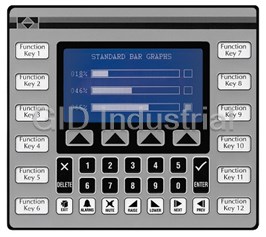
Red Lion GL350 Graphical Operator Terminal
Part Number
GL350
Price
Request Quote
Manufacturer
RED LION CONTROLS
Lead Time
Request Quote
Category
SPECIALTY PRODUCT
Specifications
Altitude
Up to 2000 meters
Construction
Steel rear metal enclosure with NEMA 4/IP65 aluminum front plate when correctly fitted with the gasket provided. This unit is rated for NEMA 4/IP65 indoor use. Installation Category II, Pollution Degree 2
Display
256 x 128 pixel full graphic display with cold cathode backlight. Automatic temperature compensation. Text formats upto 16 x 40 characters.
Keypad
4 screen legendable soft keys, 12 User user-legendable function keys, numeric pad and raise, lower, next, previous, enter, delete, exit, alarms and mute keys all are embossed and have tactile feedback
Memory
256K (192K user) battery backed RAM (Battery life expectancy 3 years 50/50 on/off cycle). Optional expansion to 768K (704K user).
Mounting Requirements
Max. panel thickness is 0.375" (9.5 mm) For NEMA 4/IP65 scaling, a steel panel with a minimum thickness of 0.125" (3.175 mm) is recommended.
Operating and Storage Humidity
20 to 80% max. RH (non-condensing) from 0°C to 40°C.
Operating Temperature
0 to 40°C
Physical Dimensions
L: 8.82" (224 mm), H: 7.84" (199 mm), D: 2.64" (67 mm).
Power Requirements
11 to 30 VDC @ 4.8 W
Power Up Current
2.5 A for 1 msec. max. Must use a Class 2 or SELV rated power supply.
SERIAL PORTS
Data Format and Baud Rates for each port is individually software programmable up to 19200 baud. Port 1: Programming Port - RS-232 on an RJ-11 jack. Port 2: RS-232 Port on a Plug-In Screw Terminal Block. Port 3: RS-485 Port on a Plug-In Screw Terminal Block (Up to 29 Units can be connected and individually addressed.) Note: LED Indicators show communications status on Ports 2 & 3
Storage Temperature
-20 to 80°C
Features
- 32 BIT / FLOATING POINT MATH
- 500 ALARM POINT LOGGER
- COMPREHENSIVE REPORT GENERATION
- CRYSTAL DISPLAY
- DIRECT, NETWORK (Including Multiple Protocol) OR MODEM LINK TO PLC
- EXPRESSION EVALUATION
- MONOCHROME 256 x 128 PIXEL CCFL LIQUID
- NEMA 4/IP65
- REAL TIME CLOCK BATTERY BACKED
- UNLIMITED PASSWORD PROTECTION
Datasheet

Extracted Text
Bulletin No. GL350-E Drawing No. LP0452 Released 2/06 Tel +1 (717) 767-6511 Fax +1 (717) 764-0839 www.redlion.net MODEL GL350 GRAPHICAL OPERATOR TERMINAL O MONOCHROME 256 x 128 PIXEL CCFL LIQUID CRYSTAL DISPLAY O 500 ALARM POINT LOGGER O COMPREHENSIVE REPORT GENERATION O UNLIMITED PASSWORD PROTECTION O REAL TIME CLOCK BATTERY BACKED O EXPRESSION EVALUATION O 32 BIT / FLOATING POINT MATH O DIRECT, NETWORK (Including Multiple Protocol) OR MODEM LINK TO PLC O NEMA 4/IP65 UL Recognized Component, File # E179259 DESCRIPTION SPECIFICATIONS The Paradigm operator interface Model GL350 was designed to meet the 1. POWER REQUIREMENTS: 11 to 30 VDC @ 4.8 W industrial demands of application power, versatility, reliability, and ease of use. Power Up Current: 2.5 A for 1 msec. max. The GL350 has provision, common to all Paradigm Family products, allowing Must use a Class 2 or SELV rated power supply. for future product upgrades and new options and capabilities are developed. 2. DISPLAY: 256 x 128 pixel full graphic display with cold cathode backlight. Automatic temperature compensation. Text formats upto 16 x 40 characters. 3. KEYPAD: 4 screen legendable soft keys, 12 User user-legendable function SAFETY SUMMARY keys, numeric pad and raise, lower, next, previous, enter, delete, exit, alarms All safety related regulations, local codes and instructions that appear in the and mute keys all are embossed and have tactile feedback manual or on equipment must be observed to ensure personal safety and to 4. MEMORY: 256K (192K user) battery backed RAM (Battery life expectancy prevent damage to either the instrument or equipment connected to it. If 3 years 50/50 on/off cycle). Optional expansion to 768K (704K user). equipment is used in a manner not specified by the manufacturer, the protection 5. ENVIRONMENTAL CONDITIONS: provided by the equipment may be impaired. Operating Temperature: 0 to 40°C Do not use this unit to directly command motors, valves, or other actuators Storage Temperature: -20 to 80°C not equipped with safeguards. To do so, can be potentially harmful to persons Operating and Storage Humidity: 20 to 80% max. RH (non-condensing) or equipment in the event of a fault to the unit. from 0°C to 40°C. The protective conductor terminal is bonded to conductive Altitude: Up to 2000 meters parts of the equipment for safety purposes and must be 6. PHYSICAL DIMENSIONS: L = 8.82" (224 mm), H = 7.84" (199 mm), connected to an external protective earthing system. D = 2.64" (67 mm). 7. CONSTRUCTION: Steel rear metal enclosure with NEMA 4/IP65 aluminum front plate when correctly fitted with the gasket provided. This unit is rated for NEMA 4/IP65 indoor use. Installation Category II, Pollution Degree 2 8. MOUNTING REQUIREMENTS: Max. panel thickness is 0.375" (9.5 mm) CAUTION: Risk of Danger CAUTION: Risk of electric shock. Read complete instructions prior to For NEMA 4/IP65 scaling, a steel panel with a minimum thickness of 0.125" installation and operation of the unit. (3.175 mm) is recommended. DIMENSIONS In inches (mm) PANEL CUT-OUT 1 9. CERTIFICATIONS AND COMPLIANCES: 10. FIELD CONNECTIONS: Removable screw terminal blocks. SAFETY 11. WEIGHT: 3.04 lb. (1.38 Kg.) UL Recognized Component, File #E179259, UL61010-1, CSA C22.2 No.61010-1 INPUT/OUTPUT COMMUNICATIONS SPECS Recognized to U.S. and Canadian requirements under the Component 1. SERIAL PORTS: Data Format and Baud Rates for each port is individually Recognition Program of Underwriters Laboratories, Inc software programmable up to 19200 baud. Type 4 Enclosure rating (Face only), UL50 Port 1: Programming Port - RS-232 on an RJ-11 jack. IECEE CB Scheme Test Certficate # US/9737/UL, Port 2: RS-232 Port on a Plug-In Screw Terminal Block CB Scheme Test Report #E179259-V01-S04 Port 3: RS-485 Port on a Plug-In Screw Terminal Block Issued by Underwriters Laboratories, Inc. (Up to 29 Units can be connected and individually addressed.) IEC61010-1, EN 61010-1:Safety requirements for electrical equipment for Note: LED Indicators show communications status on Ports 2 & 3 measurement, control, and laboratory use, Part 1. 2. COMMUNICATION MODES: Any of the three ports can be used to IP65 Enclosure rating (Face only), IEC 529 communicate with Serial Devices. ELECTROMAGNETIC COMPATIBILITY Model - (unit name) may communicate in Master mode with a different Immunity to EN 50082-2 device protocol on each port (See Note & Exception). Electrostatic discharge EN 61000-4-2 Level 2; 4 Kv contact However, only one of Ports 2 and 3 may be configured if either is selected as Level 3; 8 Kv air a Slave protocol. Electromagnetic RF fields EN 61000-4-3 Level 3; 10 V/m Note: Ports 2 and 3 may be configured as different device protocols in 80 MHz - 1 GHz Master mode and Port 1 may be used simultaneously in Slave mode for Fast transients (burst) EN 61000-4-4 Level 4; 2 Kv I/O a third device protocol. Level 3; 2 Kv power Exception: If Allen Bradley DH485 is selected on either Port 2 or 3, only 1 RF conducted interference EN 61000-4-6 Level 3; 10 V/rms Port 1 will be available for a separate Device Protocol. 150 KHz - 80 MHz Emissions to EN 50081-1 ORDERING INFORMATION RF interference EN 55022 Enclosure class B MODEL NO. DESCRIPTION PART NUMBER CCFL, 16 X 40, 12 Function, 4 Soft keys, 256 K memory GL350000 Note: GL350 CCFL, 16 X 40, 12 Function, 4 Soft keys, 768 K memory GL350010 1. Self-recoverable loss of performance during EMI disturbance at 10 Vrms: EDICT-97 Development Kit Communications error may occur during EMI disturbance. Includes Software, Manual and 9-pin RS232 SFEDT For operation without loss of performance: Programming cables I/O cables are routed in metal conduit connected to earth ground. Communication Cables P895xxxZ Battery Replacement BAL3R004 COMMON FEATURES FOR GRAPHIC BASED OPERATOR TERMINALS PROGRAMMABILITY ALARMS The Paradigm unit can monitor and log up to 500 alarms. Such triggers as a Event Driven Configuration Tool simple bit level transition, a PLC coil activation, or a complex application Edict 97, an extremely powerful Windows 95/3.11 based software program, algorithm can activate an alarm. The alarms can be time and date stamped, with provides for the intuitive configuration of every aspect of the operator an automatic screen display and/or downloading to a printer for hard copy interface’s behavior. The requirement for time consuming PLC ladder logic is recording purposes. drastically reduced by the unique event driven approach of EDICT 97. The capability of this program, in conjunction with the PLC and the Paradigm RECIPE HANDLING operator interface unit, ensures a great deal of advanced functionality for your Recipe handling in the Paradigm Operator Interfaces can be tailored to your system. This powerful PLC/Paradigm system provides many of the capabilities requirements. Using the “Data Files” section of Named Data, one can set up and features normally associated with the more complicated and costly arrays with meaningful titles, and select, edit, and maintain, recipe data up to PC/SCADA systems. Display pages are easily generated, including PLC and 8000 elements per file. In conjunction with User Programs, and the flexible data internal variables, text strings, or bar charts. All dynamic elements are also displays, the operator can select desired recipe, by number or by title, and either available as alarms, recipes, triggers, and reports for the run time software. After upload from, or download to, the target system. All the functions of EDICT97 completion of the programming, the program is directly downloaded to the are available, so the programmer can password protect the editing of the recipes operator interface from your PC, without any compiling or saving requirement. and allow for the transfer of data from a host system. When you require a change in your program, EDICT 97 loads only the change, not the entire program, saving valuable on-line time. REAL TIME SCHEDULE Real time schedule allows for repetitive or one time task to take place in the DYNAMIC DISPLAY PAGE ELEMENTS system. Typically a schedule action similar to...At 1:55 PM on Monday, Each display page has provisions to show static and dynamic information, Wednesday, and Friday print the production report...is required in the including data variables, text messages, time, and date. application. In conjunction with the recipe capabilities, a downloading of a Data Variables can be either PLC derived or internally generated, either in data special recipe can be requested by the real time schedule feature. entry or display only mode. The Paradigm unit has an extremely powerful math capability, allowing the operator to manipulate the variables to meet the USER PROGRAMS specific application’s demands. If required, the display can be formatted to This feature offers the user the ability to incorporate custom application BCD, binary, hex, floating point, and string. Upper and lower limits of data requirements via a powerful program language. For example, a program entry variables are fully supported and password protected. designated “Calculate Volume” which determines the amount of fluid in a round tank at specific temperatures could be created. This program would be triggered Text Message Animation enables several different types of animated text from a local or global message table to be displayed. The message displayed is to run and display each time the page denoted as “Volume Now” is requested. The ability to customize to your applications specialized needs is easily solved dependent on the condition of the particular controlling expression. The controlling expression may be a PLC bit level, a timer value, preset counter with the user program capability. condition, or any one of a wide variety of message triggers. KEYBOARD EDITING Time and Date in the Paradigm unit has the capability to display in any All the interface keys can be programmed to perform virtually unlimited combination of year, month, day, hours, minutes, and seconds. functions with each key, having multiple actions assigned to three types of key Bar Graphs in horizontal format are easily attached to data variables. The events: key pressed, key held down (auto repeat), and key released. Typical key partial or full length bar graph displays can be scaled and offset to optimize actions would be Gotopage, set value, load recipe, view alarms, print report, and the required display effect. many more. SECURITY The password protection scheme provides the ultimate in tamper-proof capability. Access can be limited on a unit, page, recipe, or even individual data entries. 2 COMMUNICATIONS BATTERY BACKUP ISSUES With over 70 communication drivers available, the Paradigm operator The Operator Interface is supplied with a Lithium Battery designed to interface offers a wide range of connectivity including: PLCs, Variable Speed maintain the internal memory and real-time clock during power outages. Drives, Temperature Controllers, Bar Code Readers, etc. Utilizing real PLC data Assuming the operator interface terminal is powered up for 50% of the time, references, the automatic comms configuration optimizes the system’s this battery should last over 4 years. A “Battery Low” system variable is communication performance. In the event that your specific driver does not available so that the programmer can choose specific action(s) to occur when appear on the Paradigm drivers list, let us know, as this list is always being the battery voltage drops below its nominal voltage. expanded to meet our customers’ needs. It is possible to replace the battery without losing the contents of the Operator Interface’s memory, but this does not reduce the importance of ensuring that a GRAPHIC UNITS copy of the terminal’s configuration is kept readily at hand to allow the terminal In addition to all the features of the character-based units, the GL and GX will to be re-loaded in the case of mishaps. Please remember that although an image provide exceptional value in displaying trend graphs, process schematics and of the database contents can be uploaded, this file is not editable, so the flow, and others, limited only by the imagination of the designer. The importance of keeping a copy on disk cannot be over stressed. programmer can use the built-in standard symbols, or construct them. A sequence of graphical symbols can be assigned to a PLC location, and the CHANGING THE BATTERY powerful software will step through the sequence without the necessity of programming multiple expressions for each bitmap. Some of the inherent features of the Graphical Display units: O Data Logging O Process symbols, such as tanks, valves, etc. O Extraordinary color displays on the VX-500 and VX-550. O Memory expansion is field-upgradeable. O Plus all the functions available in EDICT 97, the powerful event driven configuration tool that allows one to configure a system to do what is needed. ANIMATED GRAPHICS Graphical pages are constructed using both bitmaps and object graphics. Animation items such as tending, tank filling, horizontal and vertical bar graphs, valves, etc., make your display pages aesthetically pleasing as well as informative to the operator. HARDWARE INFORMATION This bulletin contains a variety of information related to the installation and operation of the Operator Interface supplied. Ideally, you should read this To change the internal battery, follow these steps... document thoroughly before attempting to use the equipment. For information Remove the power and PLC communications connector from the unit. about the software aspects of the terminal, please consult other documentation. Remove the four screws from the rear-cover, and remove rear cover. If you wish to avoid losing the terminal’s configuration, reconnect the CONTENTS OF PACKAGE power connector and re-apply power. Note that this will require the The Operator Interface is supplied in a packaging box containing the panel to be powered-up and, as such, only suitably qualified staff should following... carry out this procedure. The interface terminal itself. CAUTION: RISK OF ELECTRIC SHOCK A NEMA 4/IP65 rated mounting gasket. The inverter board, attached to the bottom of the main board, A bag containing panel hardware. supplies the high voltage to operate the backlight. Touching the inverter board may result in injury to personnel. This hardware bulletin. The battery is located in a holder on the main circuit board. This should If any of these items is missing, please contact your supplier be clearly visible. Remove the battery from its holder. immediately. Place the new battery in the holder. The terminal’s power supply can POWER SUPPLY REQUIREMENTS now be disconnected, if you re-applied power in the step above. The Operator Interface requires a 11-30 VDC power supply rated at 4.8 W Replace the lid, screws and connector by following the above procedure unless otherwise stated on the label. in reverse. You may like to make a note of the date the battery was The terminal may take as little as 100 mA in certain circumstances, so be replaced to allow planned maintenance to be carried out. sure that the chosen power supply can operate correctly with this load. Large switch-mode supplies tend to need a certain minimum load before If you did not keep the unit powered-up during battery replacement, hold they will operate correctly. down the EXIT and MUTE keys on the keyboard and cycle power. In any case, it is very important that the power supply is mounted correctly if Release the keys and follow the menu guides to clear the memory. The the unit is to operate reliably. A very high proportion of reported problems are unit is now ready for a configuration database to be reloaded. caused by incorrect power supply installation, so please take care to observe the following points... Please note that the old battery must be disposed of in a manner which The power supply must be mounted close to the unit, with usually not complies with your local waste regulations. Also, the battery must not be more than 6 feet of cable between the supply and the Operator Interface. disposed of in fire or in a manner whereby it may be damaged and its contents Ideally, as short a length as is possible should be used. come into contact with human skin. The wire used to connect the Operator Interface’s power supply should be of at least 22 gage wire. If a longer cable run is used, you should use heavier gage wire. The routing of the cable should be kept away from large contactors, inverters and other devices which may generate significant electrical noise. 3 Developer’s Kit. The cable is designed for a 9-way serial port. Please contact INSTALLATION & CONNECTIONS your supplier if you require a 25-way version. The unit meets NEMA 4/IP65 requirements for indoor use, when properly installed. The units are intended to be mounted into an enclosed panel. PROGRAMMING PORT PIN OUT The protective conductor terminal is bonded to conductive The Operator Interface’s programming port is sometimes used to connect parts of the equipment for safety purposes and must be other RS-232 devices, such as printers. The following illustration and table connected to an external protective earthing system. gives the pin-out of this port to enable such connections to be made. INSTALLATION ENVIRONMENT The unit should be installed in a location that does not exceed the maximum operating temperature and provides good air circulation. Placing the unit near devices that generate excessive heat should be avoided. Continuous exposure to direct sunlight may accelerate the aging process of the bezel. The bezel should be cleaned only with a soft cloth and neutral soap product. Do NOT use solvents. Do not use tools of any kind (screwdrivers, pens, pencils, etc.) to operate the keypad of the unit. Rear View of Unit MOUNTING INSTRUCTIONS The Operator Interfaces are designed for through-panel mounting. A The above table denotes the pin names of the programming port. When neoprene gasket is provided, to enable sealing to NEMA 4/IP65 specification. connecting, the pin name at the programming port is connected to the opposite The panel cut-out diagram for the model supplied is provided. All mounting of that pin name at the destination device. holes should be drilled for 0.14" (3.5 mm) clearance. Care should be taken to remove any loose material from the mounting hole to avoid such metal falling FUNCTION KEY STRIPS into the Operator Interface itself during installation. The function keys on the Models GL350, have clear windows that permit the user to insert labels appropriate to the process. A formatted page is supplied CONNECTING TO A PLC upon which the user can enter function names (e.g. RUN, PRINT, etc.). These The Operator Interface is designed to operate with a PLC. A serial strips are inserted from the rear of the panel through slots below the function communication connection must be made between the operator interface keys located underneath the gasket. terminal and PLC, and the details of this connection vary according to which Take care that the ink applied will not rub off of the paper, or else blemishes PLC is used. will be left on the inside of the window. Laminated paper or plastic film can The following section lists the connection details for the PLC to be used . prove easier to insert than normal photocopier paper. It also heips if the starting edge of the paper has about 0.25 inches of its corners cut off at a 45 degree angle. PLC TYPE Details on how to connect to most PLCs are available on request from RLC. Note: Add an additional 1.5" to label length to allow for easier insertion and removal. ® CONNECTING TO AN IBM PC/AT The Operator Interface is programmed via software running on an IBM TROUBLESHOOTING PC/AT or a compatible computer. The connection between the PC/AT and the For further technical assistance, contact technical support at the appropriate operator interface terminal is made via a custom cable provided with the EDICT company numbers listed. © 2002, RED LION CONTROLS, ALL RIGHTS RESERVED. Information in this document is subject to change without notice and does not represent a commitment by Red Lion Controls. Software, which includes any database supplied therewith, described in this document may be furnished subject to a license agreement or a nondisclosure agreement. It is against the Law to copy the software except as specifically allowed in the license or nondisclosure agreement. No part of this document may be reproduced in any form or by any means, electronic or mechanical, including photocopying and recording, for any purpose, without the express written permission of Red Lion Controls. PowerPoint and Windows are registered trademarks of Microsoft Corporation. Other product and company names mentioned herein may be the trademarks of their respective owners. Disclaimer Red Lion Controls, hereinafter referred to as RLC, will under no circumstances be responsible for direct, indirect, special, incidental or consequential damages, death or personal injury arising from the use or misuse of all or part of this documentation or the products and software described herein. Notwithstanding the above, RLC does not exclude any liability for death or personal injury caused by its negligence. RLC does not warrant any of its software products to be free from error or to be fit for any particular purpose. Neither is the software guaranteed to provide operation without interruption. The customer's sole remedy in case of failure is the refund of the purchase price of the software. The customer, in applying the products and software described herein, accepts that the products are wholly or partly programmable electronic systems that are inherently complex and which cannot thus be guaranteed to be free of errors. In doing so, the customer accepts the responsibility to ensure that the products are correctly programmed, configured, installed, commissioned, operated and maintained by competent and suitably trained staff and according to any instructions or safety instructions provided and as dictated by good engineering practices. This documentation, and the software and products described herein, is subject to continuous development and improvement. All information is given in good faith, but RLC shall not be liable for any omissions or errors herein or within the software herein described. Red Lion Controls AP Red Lion Controls Red Lion Controls BV 31, Kaki Bukit Road 3, 20 Willow Springs Circle Basicweg 11b #06-04/05 TechLink York PA 17402 NL - 3821 BR Amersfoort Singapore 417818 Tel +1 (717) 767-6511 Tel +31 (0) 334 723 225 Tel +65 6744-6613 Fax +1 (717) 764-0839 Fax +31 (0) 334 893 793 Fax +65 6743-3360
Frequently asked questions
What makes Elite.Parts unique?

What kind of warranty will the GL350 have?
Which carriers does Elite.Parts work with?
Will Elite.Parts sell to me even though I live outside the USA?
I have a preferred payment method. Will Elite.Parts accept it?
Why buy from GID?

Quality
We are industry veterans who take pride in our work

Protection
Avoid the dangers of risky trading in the gray market

Access
Our network of suppliers is ready and at your disposal

Savings
Maintain legacy systems to prevent costly downtime

Speed
Time is of the essence, and we are respectful of yours
Related Products

3-Way Isolation of Analog Signals Switch Selectable Inputs & Outputs 100 Different Input and Outpu...
0(4) to 20 mA Passive Loop Powered Isolator Provides Input/Output Isolation
Protects Against Phase Loss, Unbalance, Under Voltage, and Phase Reversal Available in 230, 380 or ...
Unregulated +12 VDC Supply (APS) Unregulated +24 VDC Supply with Current Sources (APSIS) Octal Plu...
Unregulated +12 VDC Supply (APS) Unregulated +24 VDC Supply with Current Sources (APSIS) Octal Plu...
Easily Installs to NEMA Type "C" Face Motor Frames Magnetic Pickup Versions for High Speed Applicat...
Request a Quote

The quote request has been received
Close

Facing challenges or have inquiries? Feel free to contact us!
Call Us +1-469-283-2440
What they say about us
FANTASTIC RESOURCE
One of our top priorities is maintaining our business with precision, and we are constantly looking for affiliates that can help us achieve our goal. With the aid of GID Industrial, our obsolete product management has never been more efficient. They have been a great resource to our company, and have quickly become a go-to supplier on our list!
Bucher Emhart Glass
EXCELLENT SERVICE
With our strict fundamentals and high expectations, we were surprised when we came across GID Industrial and their competitive pricing. When we approached them with our issue, they were incredibly confident in being able to provide us with a seamless solution at the best price for us. GID Industrial quickly understood our needs and provided us with excellent service, as well as fully tested product to ensure what we received would be the right fit for our company.
Fuji
HARD TO FIND A BETTER PROVIDER
Our company provides services to aid in the manufacture of technological products, such as semiconductors and flat panel displays, and often searching for distributors of obsolete product we require can waste time and money. Finding GID Industrial proved to be a great asset to our company, with cost effective solutions and superior knowledge on all of their materials, it’d be hard to find a better provider of obsolete or hard to find products.
Applied Materials
CONSISTENTLY DELIVERS QUALITY SOLUTIONS
Over the years, the equipment used in our company becomes discontinued, but they’re still of great use to us and our customers. Once these products are no longer available through the manufacturer, finding a reliable, quick supplier is a necessity, and luckily for us, GID Industrial has provided the most trustworthy, quality solutions to our obsolete component needs.
Nidec Vamco
TERRIFIC RESOURCE
This company has been a terrific help to us (I work for Trican Well Service) in sourcing the Micron Ram Memory we needed for our Siemens computers. Great service! And great pricing! I know when the product is shipping and when it will arrive, all the way through the ordering process.
Trican Well Service
GO TO SOURCE
When I can't find an obsolete part, I first call GID and they'll come up with my parts every time. Great customer service and follow up as well. Scott emails me from time to time to touch base and see if we're having trouble finding something.....which is often with our 25 yr old equipment.
ConAgra Foods