

 Manufacturers
RAULAND BORG DAX60
Description
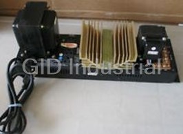
Rauland Borg DAX60 60 WATT POWER AMP
Part Number
DAX60
Price
Request Quote
Manufacturer
RAULAND BORG
Lead Time
Request Quote
Category
PRODUCTS - D
Datasheet

Extracted Text
Installation and Service KI-1480B DAX60 60-Watt Power Amplifier DAX120 120-Watt Power Amplifier Rauland-Borg Corporation Issued: 07/08/98 Page 1 of 18 Copyright 1998 by Rauland-Borg Corporation, all rights reserved. This document contains user’s information on technology that is proprietary to Rauland-Borg Corporation. Permitted transmittal, receipt, or possession of this document does not express license or imply any rights to use, sell, design or manufacture this information. No reproduction, publication, or disclosure of this information, in whole or in part, shall be made without prior written authorization from an officer of Rauland-Borg Corporation. © Rauland-Borg Corporation Rauland-Borg Corporation 3450 West Oakton Street Skokie, Illinois 60076-2958 (847) 679-0900 www.rauland.com Table of Contents GENERAL INFORMATION .............................................................................................................................................. 4 DESCRIPTION ..................................................................................................................................................................... 4 REVISION HISTORY............................................................................................................................................................. 4 DRAWINGS, DIAGRAMS, AND OTHER GRAPHICS .................................................................................................................. 5 PACKING LIST/UNPACKING PROCEDURE.............................................................................................................................. 5 INSTALLATION ................................................................................................................................................................... 5 Rack-Mounting ............................................................................................................................................................. 6 Turret-Mounting (DAX6O only) .................................................................................................................................... 6 Input Connections ......................................................................................................................................................... 7 Output Connections....................................................................................................................................................... 7 Selecting Balanced or Unbalanced Output Connections................................................................................................. 7 Grounding the Center Tap............................................................................................................................................. 8 Split-Center-Tap Operation........................................................................................................................................... 8 Auxiliary DC Power Supply........................................................................................................................................... 8 POWER CONNECTION.......................................................................................................................................................... 9 Converting the Amplifiers to 240 VAC........................................................................................................................... 9 SETTING THE "INPUT LEVEL” CONTROL .............................................................................................................................. 9 REPLACING THE FUSE......................................................................................................................................................... 9 INITIAL TROUBLESHOOTING...............................................................................................................................................10 SERVICE INFORMATION...............................................................................................................................................11 Locating the Test Points ...............................................................................................................................................11 Measuring DC Voltages ...............................................................................................................................................11 Measuring AC Voltages................................................................................................................................................12 Locating the Driver and Power Transistors ..................................................................................................................12 Removing and Replacing Transistors............................................................................................................................13 Testing Transistors.......................................................................................................................................................14 DAX6O Circuit Description .........................................................................................................................................14 DAX12O Circuit Description........................................................................................................................................14 APPENDIX A: LIMITED WARRANTY/SERVICE POLICY..........................................................................................17 LIMITED WARRANTY.........................................................................................................................................................17 ERVICE OLICY S P ................................................................................................................................................................18 NKI1480B DAX60 and DAX120 Amplifiers—Installation 1 General Information Description The Rauland DAX Series amplifiers are designed for use with Rauland's institutional program and communication Systems. They offer high-quality sound and dependability. They can be driven to their rated power output by an input signal as low as 0.3 volts. Their transformer-isolated, 25-volt balanced output matches the output of Rauland's communication panels; they also have a 70.7-volt balanced output. Their outputs can operate with a split center tap with Rauland's ® ® Telecenter 5000 and Responder 3000 systems. The amplifiers are listed by Underwriters Laboratories. The DAX amplifiers offer helpful power connections for related equipment: three 120-VAC three-pin grounded outlets, and a floating auxiliary DC power output (28 VDC, 1.2 A) that can be used for Rauland's Director Series control panels, preamplifiers, graphic equalizer, and other equipment. The amplifiers come with black-enamel face panels. Optional brushed-chrome dress panels-the RP2525 (DAX6O) and RP2700 (DAX12O)—are available. Revision History This manual has been reformatted. No substantial changes were made during the reformatting process. Page 4 of 18 (Jul-98) NKI1480B DAX60 and DAX120 Amplifiers—Installation Drawings, Diagrams, and Other Graphics This document includes the following drawings, diagrams, and/or supplemental graphics: 9 Transistor Replacement Drawing—Exploded (IL0253) Packing List/Unpacking Procedure Although the amplifier was thoroughly checked at the factory, we recommend that you inspect the amplifier, the enclosed parts, and the shipping container for signs of improper handling during shipment. In case of damage, immediately place a claim with the dealer, the distributor from whom you purchased the unit, or—if the unit was shipped directly to you—with the carrier. The following parts are included with the amplifier: Quantity Part Part Number 4 Rack-mounting screws for tapped holes (10-32 WA202 x ½ hex-head, SEMS, unslotted, machine) 4 Rack-mounting screws for untapped holes (10 WA102 x ½ pan-head, slotted, thread-forming) 4 #10 Tinnerman “U” type speed nuts for AB1889 untapped rack holes Installation The amplifier should be rack-mounted where there is adequate ventilation, a moderate temperature, an AC power outlet, and provisions for grounding. The rack should have the standard 19-inch width and a vertical space of at least 5 1/4 inches (DAX6O) or 7 inches (DAX12O). It is recommended that additional space be left above and below the amplifier to prevent hum from being introduced into adjacent equipment (such as preamplifiers), to provide additional ventilation, Page 5 of 18 (Jul-98) NKI1480B DAX60 and DAX120 Amplifiers—Installation and to allow easier access for servicing. Allowing an inch of space behind the amplifier for connections, the rack requires a total depth of seven inches. A cooling fan is recommended when the rack is enclosed and any of the following conditions exists: 9 The combined rated output power of all the equipment exceeds 250 watts RMS; or 9 The input from the AC power line exceeds 500 watts; or Restricted air flow in the rack may create extreme heat.9 Important: Failure to observe the preceding precautions could result in overheating that could damage the equipment or create a fire hazard. Rack-Mounting The DAX Series amplifiers are designed to be mounted into a standard 19-inch rack. #10 "U" nuts (AB1889) and two kinds of mounting screws are supplied with each amplifier. untapped 1. If the rack's holes are , select the #10 thread-forming screws (WA102). Push the #10 "U" nuts, their flat side facing outward, onto the proper holes in the rack. (you may have to leave the "U" nuts off if the holes are extruded). tapped 2. If the rack's holes are , select the #10 machine screws (WA202). Turret-Mounting (DAX6O only) The rack-mounting procedures can be used to install the DAX6O in a Rauland Control Turret. However, if the turret’s internal rails are used and the amplifier is oriented with its front panel facing the rear of the turret, an optional MK1O Mounting Kit will be needed. This special-order kit must be installed by factory- trained personnel. Important: 9 Do not connect AC power to the amplifier until all of the necessary input and output connections have been completed. 9 Do not disconnect the third wire on the power plug. This wire grounds the amplifier's chassis to prevent a possible shock hazard. If an adapter is used to connect the plug to a two-prong socket, make sure that the amplifier’s chassis is connected to a proven earth ground. Page 6 of 18 (Jul-98) NKI1480B DAX60 and DAX120 Amplifiers—Installation Input Connections The input is unbalanced. The input screw terminals are labeled "COM" (-) and "INPUT" (+), respectively. The terminal strip is located on the lower right corner, as viewed from the rear of the chassis. The signal source should deliver at least 300 millivolts into a 13-kilohm load. To prevent coupling, route the input cables as far from the speaker cables as possible. Output Connections The output screw terminals are located on the upper right corner, as viewed from the rear of the chassis. The following illustration shows how the output transformer's split windings are connected with a factory-installed link for most applications (for applications with the link removed, see "Split-Center-Tap Operation," below). Figure 1 The output impedances are as follows: DAX60 70.7V = 83.3 ohms 25V = 10.4 ohms DAX120 70.7V = 41.6 ohms 25V = 5.2 ohms Selecting Balanced or Unbalanced Output Connections The balanced outputs for 70.7 volts and 25 volts are for speakers designed for constant-voltage lines. Each speaker must have a line-matching transformer, and the speakers must be connected in parallel. The impedance taps on the primaries of the line-matching transformers indicate how much power will be taken from the line. Speakers can be added as required until the total wattage absorbed by all of the transformers is equal to the rated power output of the amplifier. However, it is good practice to allow an amplifier a headroom of 10% to 20%. For a 60-watt Page 7 of 18 (Jul-98) NKI1480B DAX60 and DAX120 Amplifiers—Installation amplifier, the maximum speaker load should be approximately 50 watts; for a 120- watt amplifier, the maximum speaker load should be approximately 100 watts. For unbalanced operation, place a jumper between one of the speaker terminals and “GND." Do not ground the center tap when you use unbalanced operation. Grounding the Center Tap If required by the installation, the center-tap terminals may be jumpered to the "GND” terminal when the balanced speaker output is used. The "GND" terminal is next to the negative "AUX POWER" terminal on the DAX6O; on the DAX12O, the "GND" terminal is next to the "COM" input terminal. When the two center-tap terminals are linked together, either one of them may be connected to the "GND" terminal. Important: Do not install a jumper between "GROUND" and "CT" with the unbalanced speaker connection: connecting both points to "GROUND" would create a short circuit across the output transformer Split-Center-Tap Operation The amplifier output transformer can be configured for split-center-tap operation with symmetrical output voltages on both sides of the center tap. This is intended ® for special applications with Rauland systems such as the Telecenter 5000 and the ® Responder 3000. When a DAX amplifier is used with the TC5OOO or the NCS3OOO, (a) no more than 50 watts of power may be drawn through the system, and (b) a TC5007 Transformer Module is required (see KI-1486). If the installation requires an isolated, split-center-tapped output, remove the supplied link from the two "CT" terminals; this will separate the two halves of the output windings (see "OUTPUT CONNECTIONS," above, and the attached KMO7BO). Important: There is a large capacitor inside the TC5OOO and the NCS3OOO that provides a low AC impedance across the center taps. The split windings are not designed to be used independently. Auxiliary DC Power Supply The 28-VDC terminals (on the right side of the DAX6O; below the output transformer of the DAX12O) can provide up to 1.2 Amperes to preamplifiers, Director Series control panels, and other auxiliary devices requiring DC power. Since this supply is floating, it can also be used for devices requiring an isolated Page 8 of 18 (Jul-98) NKI1480B DAX60 and DAX120 Amplifiers—Installation power source, such as Rauland's Model 6430 Pink-Noise Source and Model 6431 1/3-Octave Equalizer. Do not mix floating and grounded accessories. Power Connection Plug the power cord into a 120-V, 60-Hz, three-wire grounded outlet that can provide at least 935 watts (DAX6O) or 11O5 watts (DAX12O). Although the amplifier circuits by themselves consume no more than 175 watts (DAX6O) or 345 watts (DAX120), connecting another device to the DC output could consume another 40 watts of power, and a total load of 720 watts could be connected to the three AC sockets. Check the local regulations before installing permanent AC lines and plugging in the equipment. Converting the Amplifiers to 240 VAC If operation from a 240-VAC power source is desired, remove the front cover and locate the "120V/240V" switch inside the amplifier, on the right. Use a small screwdriver to slide the switch to the "240V" side. Re-secure the front cover. Replace the fuse with a fast-blow, 240-volt fuse with half the current rating of the supplied fuse; the new value would be 1.25 Amps for the DAX6O, 2.5 Amps for the DAX12O (see "REPLACING THE FUSE," below). Replace the plug on the power cord with one approved for 240-VAC operation. Important: When the amplifier is connected to a 240-volt supply, its three "120 VAC" convenience outlets will supply 240 volts. Accordingly, they should not be used when the amplifier is connected to 240 volts Setting the "Input Level” Control The input-level control, marked "LEVEL" on the rear chassis below the output transformer, can be adjusted with a 1/4-inch flat-blade screwdriver: turning the control clockwise will increase the output level. This control should be set so that the maximum possible input signal will not cause the output to clip. After this control has been adjusted by the installer, it should be left alone. Replacing the Fuse A current surge during operation may cause the fuse to blow. To restore power to the amplifier, first ascertain what the problem is and correct it before replacing the Page 9 of 18 (Jul-98) NKI1480B DAX60 and DAX120 Amplifiers—Installation fuse. Use a fast-blow fuse: 2.5 Amps for the DAX6O, 5 Amps for the DAX12O (but only half of these values if the amplifier is operating from a 240-VAC line). The fuse holder is on the rear of the amplifier, below the power transformer. You will need a Phillips screwdriver to remove the center plug; you may find a scissors- nosed pliers helpful in removing the fuse. If the replacement fuses continue to blow, unplug the amplifier and consult a qualified service representative. Initial Troubleshooting Consult the following troubleshooting table when experiencing any difficulties: Problem Possible Causes Check whether all the input and output connections are properly made and fastened. Low volume or distorted sound. Turn the volume down to determine if the speakers are being overdriven. Make sure the power cord is plugged in to an operating outlet. Examine the input and output lines for (1) obvious shorts (among themselves and between them and the chassis or surrounding equipment) Amplifier does not operate. and/or (2) broken connections. Replace the fuse, if all else checks out. Unplug the unit and contact your local distributor (if all else fails). There are two circuit breakers protecting this output. CB2 is a 1.6-Amp thermal breaker that shuts down the circuit when the DC current flow significantly exceeds the output’s 1.2- ampere rating, then automatically resets. It will continue cycling off and on until the problem is corrected. If the amplifier remains off, CBl (3.15 Amps) may have tripped. Check for a The 28-VDC output cycles off short in the connections; then try manually and on, or remains off. resetting CB1—by poking a small screwdriver through the access hole in the front cover (at the upper left corner of the DAX6O,or the lower left corner of the DAX12O). If the problem does not lie in the load or the connections, one of the breakers may be defective. Disconnect the load and call your Rauland distributor. Page 10 of 18 (Jul-98) NKI1480B DAX60 and DAX120 Amplifiers—Installation 2 Service Information Do not attempt to service your amplifiers unless you are an authorized technician. Important: The information that follows is intended for qualified service technicians only Locating the Test Points Whenever possible, take the voltage readings on the large connector on the main printed circuit board. You will have to remove the front cover to access it. The DAX6O has a single 16-pin connector labeled "T” on the schematic; the pins are numbered from bottom to top on the board. The DAX12O has two 16-pin connectors: the top connector and the top half of the bottom connector are referred to as "J1" on the schematic, and the rest of the bottom connector is referred to as "J2" on the schematic. The pins are numbered 1- 24 and 1-8, from top to bottom on the board. Measuring DC Voltages DC voltages are printed in rectangular boxes at various points on the schematic. When measuring these voltages on the amplifier, use a DC meter with a resistance of 1 megohm per volt and proceed as follows: Step 1. Place the amplifier on a suitable work surface and make sure that no signal is present at the input terminals. Disconnect the speakers and connect a suitable resistive load in their place: DAX6O: The load should have at least a 60-watt power rating and a value of 10.4 ohms across the 25-volt output or 83.3 ohms across the 70.7-volt output. DAX12O: The load should have at least a 120-watt power rating and a value of 5.2 ohms across the 25-volt output or 41.6 ohms across the 70.7-volt output. Step 2. Plug the amplifier into a 12Q-VAC, 60-Hz source. Step 3. On the DAX6O: Connect the meter's negative lead to the amplifier common at Connector “T-14." As you locate each DC voltage on the schematic, note the number of the nearest "T" terminal in that leg of the circuit and, if possible, take the readings between such a "T" terminal and “T-14." Page 11 of 18 (Jul-98) NKI1480B DAX60 and DAX120 Amplifiers—Installation On the DAX12O: Connect the meter's negative lead to the amplifier common at Connector "J1-13." As you locate each DC voltage on the schematic, note the number of the nearest "J" terminal in that leg of the circuit and, if possible, take the readings between such a “J” terminal and "J1-13." Measuring AC Voltages AC voltages are printed without boxes at various points on the schematic. When measuring these voltages on the amplifier, use an AC meter with a one-megohm impedance and proceed as follows: Step 1. Place the amplifier on a suitable work surface. Disconnect the speakers and replace them with a suitable resistive load: DAX6O: The load should have at least a 60-watt power rating and a value of 10.4 ohms across the 25-volt output (or 83.3 ohms across the 70.7-volt output). DAX12O: The load should have at least a 120-watt power rating and a value of 5.2 ohms across the 25-volt output or (41.6 ohms across the 70.7-volt output). Step 2. Disconnect any input device and connect a one-kilohertz signal source in its place. The source should be able to provide an amplitude of approximately 300 millivolts. Leave its output level turned down. Step 3. Plug the amplifier into a 120-VAC, 60-Hz source. Turn the input-level control fully clockwise, for maximum gain. Step 4. Connect the test leads across the 25-V or 70.7-V outputs. Slowly increase the output from the 1-KHz signal source until you obtain the rated output voltage from the DAX. Check the input level required to obtain the rated output: a reading of 300 millivolts or less is an indication that the amplifier gain is functioning properly. Step 5. On the DAX6O: Connect the meter’s negative lead to the amplifier common at Connector "T-14." As you locate each AC voltage on the schematic, note the number of the nearest "T" terminal in that leg of the circuit and, if possible, take the readings between such a “T” terminal and "T-14." On the DAX12O: Connect the meter's negative lead to the amplifier common at Connector "J1-13." As you locate each AC voltage on the schematic, note the number of the nearest "J" terminal in that leg of the circuit and, if possible, take the readings between such a "J" terminal and "J1-13." Locating the Driver and Power Transistors On both amplifiers, driver transistors Q505 and Q506 are screwed to the "L" bracket that is fastened to the large heat sink from inside the chassis. The power transistors (Q507-Q508 on the DAX6O, Q501-Q504 on the DAX12O) are fastened directly to the large heat sink from the outside (to access them, remove the protective cover). The transistors are numbered in ascending order, with the lowest number at the bottom. Page 12 of 18 (Jul-98) NKI1480B DAX60 and DAX120 Amplifiers—Installation Removing and Replacing Transistors Transistors are inherently long-lived devices that normally should not need replacement. If, however, systematic troubleshooting indicates a problem, observe these precautions when removing and replacing transistors: (1) Transistors can be damaged by excessive heat, so use a small soldering iron when removing or replacing a transistor with solder connections. (2) Transistors come with a wide variety of cases and leads. To avoid a costly mistake, make a careful sketch of the lead connections before removing a transistor from a printed circuit board or tie points. (3) Before installing a power transistor (Q507-Q508 on the DAX6O, Q501- ® insulator. If a mica insulator Q504 on the DAX12O), obtain an appropriate Silpad is used instead, coat both sides of it with silicone grease (Dow-Corning DC4 or an equivalent). Fit the insulator between the transistor and the heat sink, as shown below. Figure 2 After installing a power transistor, check for a short circuit: Step 1. On the DAX12O, isolate the circuit common from the chassis by disconnecting the wire between the negative side of C503 (the large electrolytic capacitor nearest the auxiliary 120-VAC outlets) and the star connector at the right end of the amplifier (as viewed from the front). This capacitor is not grounded to the chassis in the DAX6O. Step 2. Use an ohmmeter to check for a short between the transistor case and the heat sink. If there is a low-resistance reading, check the insulator, the screws, etc., as possible causes. Page 13 of 18 (Jul-98) NKI1480B DAX60 and DAX120 Amplifiers—Installation Step 3. After obtaining a high-resistance reading (at least 100 kilohms) between each transistor case and the heat sink, re-establish the connection between the negative side of C503 and the standard connector (DAXI2O only). Testing Transistors The best way to test a transistor is to use a transistor tester. However, if one is not available, use an ohmmeter. Most failures result in a short or an open circuit between the collector and the emitter. Connect the ohmmeter leads to the collector and the emitter, then use the low ohm range to read the resistance. If the reading in this range remains the same when the leads are reversed, the transistor is shorted. If the readings are “infinite" for both connections, the transistor is open. DAX6O Circuit Description Refer to the attached schematic, KC1546, to trace the circuit descriptions that follow. Input and Preamplifier Circuits: Resistor Ri and Capacitors Cl and C507 reject Radio Frequency Interference (RFI). RV1 is the input LEVEL control (potentiometer), which controls the signal level that is applied to the DAX's preamplifier circuits. Capacitors C2 and C8 govern the low-frequency response of the input signal, to protect horn-type speakers. Transistor Qi is a common-emitter amplifier that provides the preamplifier gain. It is also a common-base inverter for the feedback entering its emitter. Power-Amplifier Circuits: Transistor Q2 is a high-voltage-gain amplifier that drives Transistors Q3 and Q4. The latter are phase splitters that form a unity-gain configuration. Diode D503 is a negative-temperature-coefficient device mounted on the heat sink. This diode controls the DC bias for the drive and the output transistors. Transistors Q505 and Q506 are current amplifiers (drivers) that supply high base current to the output transistors, Q507 and Q508. The latter are push-pull power amplifiers that drive the output transformer. Capacitor C506 blocks DC from the output transformer and limits the low-frequency output to protect horn-type speakers. Protective Circuits: There are several protections against excessive current. Resistors R16 and R19 are current limiters; if a short occurs across the audio output, each resistor will drop 10 VDC. An excessive current surge will cause the fuse to open. In the 28-VDC supply, a short circuit on the DC output or a DC load that draws significantly more current than 1.2 Amperes will cause thermal Breaker CB2 to open within 70 seconds. It will try to reset within 15 seconds, then continue opening and closing until the short or the excessive load is removed, at which time it will remain closed for normal operation. A more serious problem will cause CB1 to open; it must be reset manually. DAX12O Circuit Description Refer to KC1547 (attached) to trace the circuit descriptions that follow. Page 14 of 18 (Jul-98) NKI1480B DAX60 and DAX120 Amplifiers—Installation Input and preamplifier circuits: Resistor R1 and Capacitors Cl and C507 filter Radio Frequency Interference (RFI). RV1 is the input LEVEL control (potentiometer), which controls the signal that is applied to the preamplifier circuits. Capacitors C2 and C9 govern the low-frequency response of the input signal, to protect horn-type speakers. Transistor Qi is a common-emitter amplifier that provides the preamplifier gain. It is also a common-base inverter for the feedback entering its emitter. Q2 is an emitter follower. Power-amplifier circuits: Transistor Q3 is a high-voltage-gain amplifier that drives Transistors Q5 and Q6. The latter, operating as phase splitters in a unity-gain configuration, provide the drive for Transistors Q505 and Q506. Q505 and Q506 are the drivers for the output transistors (Q501-Q504). Diode D503 is a negative- temperature-coefficient device mounted on the heat sink. This diode controls the DC bias for the driver and output transistors. Transistors Q501 through Q504 are push-pull power amplifiers that drive the output transformer. Capacitor C505 blocks DC from the output transformer and limits he low-frequency output to protect horn-type speakers. Protective circuits: There are several protections against excessive current. Transistors Q4 and Q7 are current limiters. If a short occurs across the audio output, the following sequence of events will occur: (1) the DC voltage across Resistors R29 and R32 will drop; (2) this drop will drive Transistors Q4 and Q7 into conduction; (3) the output of Q4 and Q7 will limit the drive to Transistors Q5 and Q6; and (4) the reduced output from Q5 and Q6 to the power transistors will reduce the overall gain (and, thereby, the total power) of the amplifier. An excessive current surge will cause the fuse to open. In the 28-VDC supply, a short circuit on the DC output or a DC load that draws significantly more current than 1.2 Amperes will cause Thermal Breaker CB2 to open within 70 seconds. It will try to reset within 15 seconds, then continue opening and closing until the short or the excessive load is removed, at which time it will remain closed for normal operation. A more serious problem will cause CB1 to open; it must be reset manually. Specifications DAX6O: 60 watts RMS Rated Power Output DAX12O: 120 watts RMS Frequency Response +-1.5 dB from 40 Hz to 15 kHz at -3 dB from RPO. Less than 3% from 60 Hz to 15 kHz Harmonic Distortion 84 dB with LEVEL control at maximum setting 90dB Noise Level with LEVEL control at minimum setting Input Impedance 13 kilohms Input Sensitivity for Rated 0.3 V Power Output DAX6O: 105-130 VAC, 60 Hz, 935 watts (including the AC and DC outputs) Power Requirements DAX12O: 105-130 VAC, 60 Hz, 1105 watts (including the AC and DC outputs) Supplies 1.2 Amperes at 28 VDC Auxiliary DC Output DAX60 DAX120 AC Power Consumption No Signal 12 Watts 12 Watts (28 VDC Auxiliary Output Disconnected) 1/3 RPO 105 Watts 210 Watts Page 15 of 18 (Jul-98) NKI1480B DAX60 and DAX120 Amplifiers—Installation Full RPO 175 Watts 345 Watts DAX60 DAX120 AC Power Consumption No Signal 50 Watts 50 Watts (28 VDC Auxiliary Output 1/3 RPO 145 Watts 250 Watts Fully Loaded) Full RPO 215 Watts 385 Watts AC Convenience Outlets 720 watts maximum 0 0 0 0 Operating Temperature 0 F to 130 F (-17.8-0 C to 54.4 C) Fast-blow fuse: 2.5A (DAX6O), 5A (DAX12O) Line Protection 1.6-Amp thermal breaker, auto reset; 28 VDC Protection 3.15-Amp breaker, manually reset DAX6O: 19" W, 5-1/4" H, 6-1/2" D (48.3 cm x 13.3 cm x 16.5 cm) Size DAX12O: 19" W, 6-3/4" H, 6-1/2" D (48.3 cm x 17.2 cm x 16.5 cm) DAX6O: 23 lb. (10.42 kg) Unit Weight DAX12O: 27lb (12.23 kg) Page 16 of 18 (Jul-98) NKI1480B DAX60 and DAX120 Amplifiers—Installation A Appendix A: Limited Warranty/Service Policy Limited Warranty This warranty supersedes any warranty or guarantee that may appear on any printed material packed with any product or any warranty or guarantee previously issued by Rauland-Borg Corporation. Rauland-Borg Corporation warrants equipment manufactured by it to be free from defects in material and workmanship arising from normal usage for a period of one year from date of shipment by Rauland-Borg. Our obligation under this warranty is limited to repairing any such defect and/or replacing any such defective part, provided the unit and/or the defective part is returned to us, transportation prepaid, within one year after date of original shipment by Rauland-Borg and found by our inspection to be defective in materials and workmanship. The obligation of Rauland-Borg Corporation is limited to the above and does not include either the cost or the furnishing of any labor in connection with the repair of any such defect and/or replacement of any such defective part unless accomplished at Rauland-Borg, nor does it include responsibility for any transportation expense. This warranty is extended only to the original purchaser chaser from Rauland-Borg and is not transferable, and covers only equipment either installed by or under the direct supervision of a factory-trained arid authorized Rauland distributor. This warranty does not extend to any product which has been subject to misuse, neglect, accident, improper repair, or alteration. Accessories not of our manufacture used with this equipment are not covered by this warranty. All implied warranties, including but not limited to implied warranties of fitness and merchantability, are limited in duration to a period ending one year from the dale of shipment by' Rauland-Borg. Page 17 of 18 (Jul-98) NKI1480B DAX60 and DAX120 Amplifiers—Installation All material returned to Rauland-Borg Corporation under this warranty must be accompanied with information concerning the nature of the defect, the original date of shipment, original invoice number, and, if a defective component, the model number of the unit from which it was removed. This warranty is in lieu of all other agreements arid warranties, general or special, expressed or implied, and no representative or person is authorized to assume for us any other liability in connection with the sale or use of our products. Service Policy The entire Rauland-Borg organization is interested in the proper maintenance of your equipment for as long as you own it. Our national network of Rauland-Borg distributors is at the service of all purchasers of our products. Should you have a problem with your equipment, or require any advice or assistance, contact your local Rauland-Borg distributor. If you are not able to locate a local Rauland-Borg distributor, the information or action that you want can be obtained by writing to our Sales Engineering Department, at the address shown above. No end-user replaceable components are contained within this equipment. Refer servicing to your local Rauland-Borg distributor. Important: Any attempt at self-service of this equipment may result in exposure to electrical shock, or in extensive damage to the equipment and possible voiding of the equipment warranty. Page 18 of 18 (Jul-98)
Frequently asked questions
What makes Elite.Parts unique?

What kind of warranty will the DAX60 have?
Which carriers does Elite.Parts work with?
Will Elite.Parts sell to me even though I live outside the USA?
I have a preferred payment method. Will Elite.Parts accept it?


What they say about us
FANTASTIC RESOURCE
One of our top priorities is maintaining our business with precision, and we are constantly looking for affiliates that can help us achieve our goal. With the aid of GID Industrial, our obsolete product management has never been more efficient. They have been a great resource to our company, and have quickly become a go-to supplier on our list!
Bucher Emhart Glass
EXCELLENT SERVICE
With our strict fundamentals and high expectations, we were surprised when we came across GID Industrial and their competitive pricing. When we approached them with our issue, they were incredibly confident in being able to provide us with a seamless solution at the best price for us. GID Industrial quickly understood our needs and provided us with excellent service, as well as fully tested product to ensure what we received would be the right fit for our company.
Fuji
HARD TO FIND A BETTER PROVIDER
Our company provides services to aid in the manufacture of technological products, such as semiconductors and flat panel displays, and often searching for distributors of obsolete product we require can waste time and money. Finding GID Industrial proved to be a great asset to our company, with cost effective solutions and superior knowledge on all of their materials, it’d be hard to find a better provider of obsolete or hard to find products.
Applied Materials
CONSISTENTLY DELIVERS QUALITY SOLUTIONS
Over the years, the equipment used in our company becomes discontinued, but they’re still of great use to us and our customers. Once these products are no longer available through the manufacturer, finding a reliable, quick supplier is a necessity, and luckily for us, GID Industrial has provided the most trustworthy, quality solutions to our obsolete component needs.
Nidec Vamco
TERRIFIC RESOURCE
This company has been a terrific help to us (I work for Trican Well Service) in sourcing the Micron Ram Memory we needed for our Siemens computers. Great service! And great pricing! I know when the product is shipping and when it will arrive, all the way through the ordering process.
Trican Well Service
GO TO SOURCE
When I can't find an obsolete part, I first call GID and they'll come up with my parts every time. Great customer service and follow up as well. Scott emails me from time to time to touch base and see if we're having trouble finding something.....which is often with our 25 yr old equipment.
ConAgra Foods