Intellicom
Models OP6600 and OP6700
User’s Manual
019–0078 • 090529–J
Intellicom User’s Manual
Part Number 019-0078 • 090529–J • Printed in U.S.A.
©2000–2009 Digi International Inc. • All rights reserved.
No part of the contents of this manual may be reproduced or transmitted in any form or by any means
without the express written permission of Digi International.
Permission is granted to make one or more copies as long as the copyright page contained therein is
included. These copies of the manuals may not be let or sold for any reason without the express written
permission of Digi International.
Digi International reserves the right to make changes and
improvements to its products without providing notice.
Trademarks
Rabbit and Dynamic C are registered trademarks of Digi International Inc.
Rabbit 2000 and RabbitCore are trademarks of Digi International Inc.
The latest revision of this manual is available on the Rabbit Web site, www.rabbit.com,
for free, unregistered download.
Digi International Inc.
www.rabbit.com
Intellicom (OP6600/OP6700)
TABLE OF CONTENTS
Chapter 1. Introduction 1
1.1 Features.................................................................................................................................................1
1.2 Development and Evaluation Tools......................................................................................................3
1.2.1 Tool Kit .........................................................................................................................................3
1.2.2 Software ........................................................................................................................................3
1.3 CE Compliance .....................................................................................................................................4
1.3.1 Design Guidelines .........................................................................................................................5
1.3.2 Interfacing the Intellicom to Other Devices..................................................................................5
Chapter 2. Getting Started 7
2.1 Power Supply Connections...................................................................................................................8
2.2 Demonstration Program on Power-Up ...............................................................................................10
2.3 Programming Cable Connections .......................................................................................................12
2.4 Installing Dynamic C ..........................................................................................................................13
2.5 Starting Dynamic C ............................................................................................................................14
2.6 PONG.C..............................................................................................................................................15
2.7 Where Do I Go From Here? ...............................................................................................................16
Chapter 3. Subsystems 17
3.1 Intellicom Subsystems ........................................................................................................................18
3.1.1 Digital Inputs...............................................................................................................................19
3.1.2 Digital Outputs............................................................................................................................19
3.2 Serial Communication ........................................................................................................................20
3.2.1 RS-232 ........................................................................................................................................23
3.2.2 RS-485 ........................................................................................................................................23
3.2.3 Programming Port.......................................................................................................................26
3.3 Programming Cable ............................................................................................................................27
3.3.1 Changing Between Program Mode and Run Mode ....................................................................27
3.4 Memory...............................................................................................................................................28
3.4.1 SRAM .........................................................................................................................................28
3.4.2 Flash Memory .............................................................................................................................28
3.4.3 Dynamic C BIOS Source Files ...................................................................................................28
3.5 Speaker................................................................................................................................................29
3.6 Vacuum Fluorescent Display..............................................................................................................29
3.7 Other Hardware...................................................................................................................................30
3.7.1 Clock Doubler.............................................................................................................................30
3.7.2 Spectrum Spreader ......................................................................................................................30
Chapter 4. Software 31
4.1 Running Dynamic C ...........................................................................................................................31
4.1.1 Upgrading Dynamic C ................................................................................................................33
4.1.1.1 Patches and Bug Fixes........................................................................................................ 33
4.1.1.2 Upgrades............................................................................................................................. 33
4.2 Sample Programs ................................................................................................................................34
4.2.1 General Intellicom Operation......................................................................................................34
4.3 Dynamic C Libraries...........................................................................................................................36
User’s Manual
4.4 Intellicom Function Calls................................................................................................................... 37
4.4.1 Board Initialization..................................................................................................................... 37
4.4.2 Digital I/O................................................................................................................................... 37
4.4.3 Serial Communication ................................................................................................................ 38
4.4.4 Keypad Controls......................................................................................................................... 39
4.4.5 Display Controls......................................................................................................................... 41
4.4.6 Speaker Controls ........................................................................................................................ 44
Chapter 5. Using the TCP/IP Features 45
5.1 TCP/IP Connections........................................................................................................................... 45
5.2 Running TCP/IP Sample Programs.................................................................................................... 47
5.3 How to Set IP Addresses in the Sample Programs.............................................................................49
5.4 How to Set Up Your Computer’s IP Address For Direct Connect .................................................... 50
5.5 Run the PINGME.C Demo................................................................................................................. 51
5.6 Running More Demo Programs With a Direct Connection ............................................................... 51
5.7 Where Do I Go From Here?............................................................................................................... 52
Appendix A. Intellicom Specifications 53
A.1 Electrical and Mechanical Specifications.......................................................................................... 54
A.2 Conformal Coating............................................................................................................................ 56
A.3 Jumper Configurations ...................................................................................................................... 57
Appendix B. Keypad and Plastic Enclosure 59
B.1 Keypad Insert..................................................................................................................................... 60
B.2 Plastic Enclosure................................................................................................................................ 62
B.2.1 Assembling Intellicom Enclosure.............................................................................................. 64
B.2.1.1 Custom Mounting In An Opening .................................................................................... 64
B.2.1.2 Supplied Outer Casing ...................................................................................................... 65
Appendix C. Power Management 67
C.1 Power Supplies .................................................................................................................................. 67
C.2 Batteries and External Battery Connections...................................................................................... 68
C.2.1 Battery-Backup Circuit.............................................................................................................. 68
C.2.2 Power to VRAM Switch............................................................................................................ 69
C.2.3 Reset Generator.......................................................................................................................... 70
C.2.4 Replacing the Backup-Battery Board ........................................................................................ 70
C.3 Chip Select Circuit............................................................................................................................. 71
Appendix D. Running Sample Programs 73
D.1 Connecting Demonstration Board ..................................................................................................... 74
D.2 Running Sample Program DEMOBRD1.C....................................................................................... 75
D.2.1 Single-Stepping ......................................................................................................................... 76
D.2.1.1 Watch Expression ............................................................................................................. 76
D.2.1.2 Break Point ....................................................................................................................... 76
D.2.1.3 Editing the Program.......................................................................................................... 77
D.2.1.4 Watching Variables Dynamically..................................................................................... 77
D.2.1.5 Summary of Features........................................................................................................ 77
D.2.2 Cooperative Multitasking .......................................................................................................... 78
D.2.3 Advantages of Cooperative Multitasking .................................................................................. 80
Index 81
Schematics 85
Intellicom (OP6600/OP6700)
1. INTRODUCTION
The Intellicom intelligent terminal interface is a high-perfor-
mance, C-programmable terminal that offers built-in I/O and
®
Ethernet connectivity. A Rabbit 2000 microprocessor operating
at 18.5 MHz provides fast data processing.
1.1 Features
• C-programmable to create a custom user interface
4 protected logic-level digital inputs
4 protected sinking digital outputs
High-visibility backlit 4 × 20 LCD
10Base-T Ethernet interface
TCP/IP capability
RS-232 and RS-485 serial ports
128K SRAM and 256K–512K flash EPROM
Self-healing lens is scratch, impact, and abrasion-resistant
Real-time clock
Watchdog supervisor
Voltage regulator
Backup battery
Can be programmed to emulate a serial terminal
Splash-resistant when panel-mounted using the supplied gasket
Can be wall-mounted or panel-mounted
Appendix A provides detailed specifications for the Intellicom.
User’s Manual 1
Two versions of the Intellicom are available. Their standard features are summarized in
Table 1.
Table 1. Intellicom Series Features
Model Features
Standard terminal without Ethernet interface and only
OP6600
256K flash EPROM.
Full-featured terminal with Ethernet interface and 512K
OP6700
flash EPROM.
Both models are available with a vacuum fluorescent display instead of the LCD.
Visit our Web site for up-to-date information about additional add-ons and features as they
become available. The Web site also has the latest revision of this user’s manual.
2 Intellicom (OP6600/OP6700)
1.2 Development and Evaluation Tools
1.2.1 Tool Kit
The Tool Kit has the essentials that you need to understand and program your own Rabbit-
based display unit.
The items in the Tool Kit and their use are as follows:
Intellicom Getting Started instructions.
Dynamic C CD-ROM, with complete product documentation on disk.
Demonstration Board. The Demonstration Board includes pushbutton switches and
LEDs, and can be connected to the Intellicom board. Programs that run on the Demon-
stration Board can be used to flash the LEDs and otherwise demonstrate the capabilities
of the Intellicom terminal.
Programming cable. The programming cable is used to connect your PC serial port to
the Intellicom to write and debug C programs that run on the Intellicom board.
Wire assembly to connect Intellicom board to Demonstration Board.
Screwdriver.
Universal AC adapter (includes Canada/Japan/U.S., Australia/N.Z., U.K., and Euro-
pean style plugs). The AC adapter is used to power the Intellicom board. A power supply
of 12 V at up to 500 mA is recommended. The Intellicom can also be powered from
any DC voltage source between 9.0 V and 40 V.
1.2.2 Software
The Intellicom is programmed using Rabbit’s Dynamic C. A compatible version is included
on the Tool Kit CD-ROM. Dynamic C v. 9.60 includes the popular µC/OS-II real-time oper-
ating system, point-to-point protocol (PPP), FAT file system, RabbitWeb, and other select
libraries that were previously sold as individual Dynamic C modules.
Rabbit also offers for purchase the Rabbit Embedded Security Pack featuring the Secure
Sockets Layer (SSL) and a specific Advanced Encryption Standard (AES) library. In addi-
tion to the Web-based technical support included at no extra charge, a one-year telephone-
based technical support subscription is also available for purchase. Visit our Web site at
www.rabbit.com for further information and complete documentation, or contact your
Rabbit sales representative or authorized distributor.
User’s Manual 3
1.3 CE Compliance
Equipment is generally divided into two classes.
CLASS A CLASS B
Digital equipment meant for light industrial use Digital equipment meant for home use
Less restrictive emissions requirement:
More restrictive emissions requirement:
less than 40 dB µV/m at 10 m
30 dB µV/m at 10 m or 100 µV/m
(40 dB relative to 1 µV/m) or 300 µV/m
These limits apply over the range of 30–230 MHz. The limits are 7 dB higher for frequencies
above 230 MHz. Although the test range goes to 1 GHz, the emissions from Rabbit-based
systems at frequencies above 300 MHz are generally well below background noise levels.
The OP6700 operator interface has been tested and was found to be in
conformity with the following applicable immunity and emission stan-
dards. The OP6600 operator interface is also CE qualified as it is a sub-
version of the OP6700 operator interface. Boards that are CE-compli-
ant have the CE mark.
NOTE: Earlier versions of the Intellicom sold before 2003 that do not have the CE mark
are not CE-complaint.
Immunity
The Intellicom series of operator interfaces meets the following EN55024/1998 immunity
standards.
EN61000-4-2 (ESD)
EN61000-4-3 (Radiated Immunity)
EN61000-4-4 (EFT)
EN61000-4-6 (Conducted Immunity)
Additional shielding or filtering may be required for a heavy industrial environment.
Emissions
The Intellicom series of operator interfaces meets the following emission standards emis-
sion standards with the Rabbit 2000 spectrum spreader turned on and set to the normal
mode. The spectrum spreader is only available with Rev. C or higher of the Rabbit 2000
microprocessor. This microprocessor is used on the Intellicom operator interfaces that
carry the CE mark.
EN55022:1998 Class B
FCC Part 15 Class B
Your results may vary, depending on your application, so additional shielding or filtering
may be needed to maintain the Class B emission qualification.
4 Intellicom (OP6600/OP6700)
1.3.1 Design Guidelines
Note the following requirements for incorporating the Intellicom series of operator inter-
faces into your application to comply with CE requirements.
General
The power supply provided with the Tool Kit is for development purposes only. It is the
customer’s responsibility to provide a CE-compliant power supply for the end-product
application.
When connecting the Intellicom to outdoor cables, the customer is responsible for pro-
viding CE-approved surge/lighting protection.
Rabbit recommends placing digital I/O or analog cables that are 3 m or longer in a
metal conduit to assist in maintaining CE compliance and to conform to good cable
design practices.
When installing or servicing the Intellicom, it is the responsibility of the end-user to use
proper ESD precautions to prevent ESD damage to the Intellicom.
Safety
All inputs and outputs to and from the Intellicom must not be connected to voltages
exceeding SELV levels (42.4 V AC peak, or 60 V DC).
The lithium backup battery circuit on the Intellicom has been designed to protect the
battery from hazardous conditions such as reverse charging and excessive current
flows. Do not disable the safety features of the design.
1.3.2 Interfacing the Intellicom to Other Devices
Since the Intellicom operator interfaces are designed to be connected to other devices,
good EMC practices should be followed to ensure compliance. CE compliance is ulti-
mately the responsibility of the integrator. Additional information, tips, and technical
assistance are available from your authorized Rabbit distributor, and are also available on
our Web site at www.rabbit.com.
User’s Manual 5
6 Intellicom (OP6600/OP6700)
2. GETTING STARTED
Chapter 2 explains how to connect the power supply to the Intel-
licom board and how to connect the programming cable from
the Intellicom board to your PC. Once you run a sample pro-
gram to demonstrate that you have connected everything cor-
rectly, you will be ready to go on and finish developing your
system.
User’s Manual 7
� �
� �
!�
!�
!�
�
!�
#�
#�
#�
#�
�"
�"
���
���
���
����
��
� �
��
�� $��!%
2.1 Power Supply Connections
1. Remove and set aside outer casing and rubber gasket.
Before proceeding, remove and set aside the outer casing, rubber gasket, screws, and
panel-mount brackets included with your Intellicom unit, shown in Figure 1. The outer
casing and rubber gasket are not attached to the front panel when the Intellicom is shipped.
Take care not to damage the rubber gasket.
���������
�����������������
����������������
��������������������
�� � � � �
�� � � � �����
Figure 1. Remove and Set Aside Outer Casing and Accessory Parts
2. Position Intellicom board.
The Intellicom board is attached to the back of the front panel. Turn the front panel assem-
bly over so that the Intellicom board is facing up as shown in Figure 2.
�� �&85>&�4;5*�95>&, �� �� @
���� ��
�� ��
��
� ��"�������
� � �� �
��
-.4&,*�*)1�-.*5�4;5*
��
��� ���
�� ��
�� ��� ���
�� ����������
�
����������� ��
���
��
���������� �� ���
�� ���
��
���
����
���
��
��
�����
����
�.):�:;02�-.*5�:;)9&
� ��� �� ����
��
�� �����
����
����
�����
��� ��� ����
��� ����
���� �� ���������4+56.7
���
�� �58&�958:5.&.*4
),&�;)-’�50*�4;-2+*;<
��� �� ��� ����
����� ���� ’-==&,&.*;<�5.�5;’&,
����
��
�� ����� >&,4-5.4?
����
���
��
��� ���
��"�������
���
�� ���
���
��� ���
��
��!� ���
�� ��
���
���
�!��
���
���
��� ���
���
� ��
�
���
��� ���
�
� ���
���
�� ��� ���
���
��� ��
�� ��
��� ���
�� ���
��� ��� ���
��� ��� ���
���
���
���
��� ���
��� ���
���
��
���
���
��
��
��� ��� ��� �� �� ��� ���
��
���
��� ��� ��� ���
���
������ ��� ��� ��� ��� ���������������������
��
� � ��
�
����� ���� ���� � ����
� 3
�&’
(&)*��+,-./
�01-.2
Figure 2. Power Supply Connections
8 Intellicom (OP6600/OP6700)
���
�� ���
���
��
��
��
���
���
���
���
��� ��� ���
���
���
���
��
��
���
��� ��� ���
���
���
��
��� ���
���
��� ���
���
���
��� ���
���
���
���
���
���
���
���
���
���
��
���
���
���
���
���
���
��� ���
���
���
���
���
���
���
���
���
��� ���
�
�
���
���
3. Connect Power Supply to the Intellicom
Board
First, prepare the AC adapter for the country
�
����� ���� ����
where it will be used by selecting the plug. The
Intellicom Tool Kit presently includes Can-
3
�
ada/Japan/U.S., Australia/N.Z., U.K., and Euro- �&’
(&)*��+,-./
pean style plugs. Snap in the top of the plug
�01-.2
assembly into the slot at the top of the AC adapter
as shown in Figure 2, then press down on the
spring-loaded clip below the plug assembly to
Figure 3. Power Supply Connections—
allow the plug assembly to click into place.
Detailed View
Connect the positive lead (indicated with red heat-shrink tubing on the AC adapter
included with the Tool Kit) to the PWR connector on header J7 on the Intellicom Board
and connect the negative lead to GND on header J7 as shown in Figure 2 and Figure 3.
CAUTION: Be careful to hook up the positive and negative power leads exactly as
described. Otherwise, the Intellicom board will not function.
4. Apply power.
Plug in the AC adapter. The Intellicom board is now ready to be used.
NOTE: A hardware RESET is accomplished by unplugging the AC adapter, then plug-
ging it back in.
User’s Manual 9
2.2 Demonstration Program on Power-Up
The following sequence of messages will be displayed on the LCD when power is first
applied to the Intellicom board. Note that the programming cable must not be connected.
��������� ((((((((((((
�
�
)�*+���"�
�����������������
���������������� � ,,���
��������������������
((((((((((((
�������������� ------------
�
�
���������������� �,��+��
���� ���!�"������� �������
����#�����$$$ ------------
%%%%%%%%%%%% ............
�
�
��& ������ � ����
�������� ��/�����
’’’’’’’’’’’’ ............
��#�0� ���12
10 Intellicom (OP6600/OP6700)
The contrast, backlight, speaker volume, and cursor positions will change automatically
through the demonstration. Then there is an opportunity for you to vary these settings by
responding to prompts on the LCD.
1. Choose which feature (LCD con-
trast, backlight on/off, speaker, or
������345���������
cursor) you wish to change.
������365�)�*+���"�
������375��,��+��
������385�� ����
2. Press [1] to select the contrast
adjustment demonstration.
9�*+���� ,������*"2
������345
3. Press [1] to increase contrast, press
[6] to decrease contrast, or press
[Enter] to get to choose another
feature.
)����������*+���#�
������3:5
������3�����5�������
4. Press [2] to select the backlight
���"����
demonstration. Press [2] to toggle
���"�����
backlight on or off, or press [Enter]
������365
to get to choose another feature.
������3�����5�������
5. Press [3] to select the speaker dem-
onstration. Press [1]–[4] to set the
;�� ��-�������345<385
desired speaker volume ([1] is min,
=��>-�������3?5����3@5
[4] is max), press [5] or [0] to
;�� �����/��
increase or decrease frequency, or
=��>���/��
press [Enter] to get to choose
another feature. The volume and
frequency are displayed.
385
6. Press [4] to select the cursor dem-
3A5�������+�1��3@5
onstration. Press keys as shown to
3B5
move cursor, or press [Enter] to get ������3�����5�������
to choose another feature.
This demonstration will be replaced by a new program when the programming cable is
attached and the new program is compiled and run. The demonstration is available for
future reference in the Dynamic C SAMPLES directory as ICOMDEMO.C.
User’s Manual 11
� �
� �
�#��
!�
!�
��!�
!�
�
!�
#�
#�
#�
#�
�"
�"
���
���
���
����
��
� �
��
�� $��!%
2.3 Programming Cable Connections
1. Connect the programming cable to the Intellicom board.
Connect the 10-pin PROG connector of the programming cable to header J4 on the Intelli-
com board as shown in Figure 4. Be sure to orient the red edge of the cable towards pin 1 of
the connector. (Do not use the DIAG connector, which is used for a normal serial connection.)
NOTE: Never disconnect the programming cable by pulling on the ribbon cable.
Carefully pull on the connector to remove it from the header.
NOTE: Some PCs now come equipped only with a USB port. It may be possible to use an
RS-232/USB converter (Part No. 20-151-0178) with the programming cable supplied
with the Intellicom Tool Kit. Note that not all RS-232/USB converters work with
Dynamic C.
�� �� ��
���� ��
�� �� ��
� � �� ��"������� �
��
��
��� ���
�� �� ��� �� ���
��
��
����������� �� �
���
��
�� ���
�� ���
��
���
����
���
��
��
����� ����
�� ����
��� ��
�� ����� ����
����
��� �����
��� ����
��� ����
���� ��
���
��
��� �� ��� ����
����� ����
�� ����
�� �����
����
���
��
��� ���
��"�������
��� �5
�� ���
���
���
���
��� ��
��!� ��
�� ��� �������:5,*
�!�� ���
��� ���
��� ���
���
� ��
�
���
��� ���
� �
��� ���
��� ���
��� ��
��� ��
�� ��� �� ���
�� ���
��� ��� ��� �5;5,&’�4-’&
��� ��� ��� ���
���
��� ��� ���
��� ��� ’56.
���
��� ��
���
��
��
��� ��� ��� �� �� ��� ���
��
���
��� ��� ��� ���
���
������ ��� ��� ��� ��� ���������������������
��
� � ��
�
����� ���� ����
� ����
� 3
�&’
(&)*��+,-./
�01-.2
Figure 4. Programming Cable Connections
NOTE: Be sure to use the programming cable (Part No. 101-0513) supplied with the
Intellicom Tool Kit—the programming cable has red shrink wrap around the RS-232
converter section located in the middle of the cable. Programming cables from other
Rabbit kits are not designed to work with the Intellicom.
2. Apply power.
Reset the Intellicom by unplugging the AC adapter, then plugging it back in. The Intelli-
com board is now ready to be used.
NOTE: A hardware RESET is accomplished by unplugging the AC adapter, then plug-
ging it back in.
To power down the Intellicom, unplug the AC adapter. You should disconnect power
before making any circuit adjustments or changing any connections to the board.
12 Intellicom (OP6600/OP6700)
���
�� ���
���
��
��
��
���
���
���
���
��� ���
���
���
���
���
��
��
��� ���
��� ���
���
���
��
���
���
���
��� ���
���
���
���
���
���
���
���
���
���
���
��� ���
���
��
���
���
���
���
���
���
��� ���
���
���
���
���
���
���
���
���
��� ���
�
�
2.4 Installing Dynamic C
If you have not yet installed Dynamic C, do so now by inserting the Dynamic C CD from
the Intellicom Tool Kit in your PC’s CD-ROM drive. The CD will auto-install unless you
have disabled auto-install on your PC.
If the CD does not auto-install, click Start > Run from the Windows Start button and
browse for the Dynamic C setup.exe file on your CD drive. Click OK to begin the
installation once you have selected the setup.exe file.
The online documentation is installed along with Dynamic C, and an icon for the docu-
mentation menu is placed on the workstation’s desktop. Double-click this icon to reach the
menu. If the icon is missing, create a new desktop icon that points to default.htm in the
docs folder, found in the Dynamic C installation folder.
The latest versions of all documents are always available for free, unregistered download
from our web sites as well.
The Dynamic C User’s Manual provides detailed instructions for the installation of
Dynamic C and any future upgrades.
NOTE: If you have an earlier version of Dynamic C already installed, the default instal-
lation of the later version will be in a different folder, and a separate icon will appear on
your desktop.
User’s Manual 13
2.5 Starting Dynamic C
Once the Intellicom is connected to your PC and to a power source, start Dynamic C by double-
clicking on the Dynamic C icon on your desktop or in your Start menu.
If you are using a USB port to connect your computer to the Intellicom, choose Options >
Project Options and select “Use USB to Serial Converter.” Click OK.
Dynamic C defaults to using the serial port on your PC that you specified during installa-
tion. If the port setting is correct, Dynamic C should detect the Intellicom and go through
a sequence of steps to cold-boot the Intellicom and to compile the BIOS. (Some versions
of Dynamic C will not do the initial BIOS compile and load until the first time you com-
pile a program.)
If you receive the message No Rabbit Processor Detected, the programming
cable may be connected to the wrong COM port, a connection may be faulty, or the target
system may not be powered up. First, check both ends of the programming cable to ensure
that it is firmly plugged into the PC and the programming port with the marked (colored)
edge of the programming cable towards pin 1 of the programming header.
If there are no faults with the hardware, select a different COM port within Dynamic C.
From the Options menu, select Communications. Select another COM port from the list,
then click OK. Press to force Dynamic C to recompile the BIOS. If Dynamic C
still reports it is unable to locate the target system, repeat the above steps until you locate the
active COM port. You should receive a Bios compiled successfully message
once this step is completed successfully.
If Dynamic C appears to compile the BIOS successfully, but you then receive a communi-
cation error message when you compile and load a sample program, it is possible that your
PC cannot handle the higher program-loading baud rate. Try changing the maximum
download rate to a slower baud rate as follows.
Locate the Serial Options dialog in the Dynamic C Options > Communications
menu. Select a slower Max download baud rate.
If a program compiles and loads, but then loses target communication before you can
begin debugging, it is possible that your PC cannot handle the default debugging baud
rate. Try lowering the debugging baud rate as follows.
Locate the Serial Options dialog in the Dynamic C Options > Communications
menu. Choose a lower debug baud rate.
14 Intellicom (OP6600/OP6700)
2.6 PONG.C
You are now ready to test your set-up by running a sample program.
Find the file PONG.C, which is in the Dynamic C SAMPLES folder. To run the program,
open it with the File menu (if it is not still open), compile it using the Compile menu, and
then run it by selecting Run in the Run menu. The STDIO window will open and will dis-
play a small square bouncing around in a box.
This program does not test the serial ports, the I/O, or the TCP/IP part of the board, but
does ensure that the board is basically functional. The sample program in Section 5.5,
“Run the PINGME.C Demo,” tests the TCP/IP portion of the board.
User’s Manual 15
2.7 Where Do I Go From Here?
NOTE: If you purchased your Intellicom through a distributor or Rabbit partner, contact
the distributor or partner first for technical support.
If there are any problems at this point:
Use the Dynamic C Help menu to get further assistance with Dynamic C.
Check the Rabbit Technical Bulletin Board and forums at www.rabbit.com/support/bb/
and at www.rabbit.com/forums/.
Use the Technical Support e-mail form at www.rabbit.com/support/.
If the sample program ran fine, you are now ready to go on to explore other Intellicom fea-
tures and develop your own applications.
Chapter 3, “Subsystems,” provides a description of the Intellicom board’s features,
Chapter 4, “Software,” describes the Dynamic C software libraries and introduces some
sample programs, and Chapter 5, “Using the TCP/IP Features,” explains the TCP/IP fea-
tures.
16 Intellicom (OP6600/OP6700)
3. SUBSYSTEMS
Chapter 3 describes the principal subsystems for the Intellicom.
• Intellicom Subsystems
• Serial Communication
• Memory
• Speaker
• Other Hardware
User’s Manual 17
3.1 Intellicom Subsystems
Figure 5 shows the Rabbit-based subsystems designed into the Intellicom.
���3 ��� ��� ���3��� ���
���3���
��� ���3��� ���
��� ���
������
������ ������
���
� �@�� �3� �
������������ ����������
������
���
/�����$0
��������������
� �@�� �3� �
���3���
����-(�)��$���*
���&��))��&
���3��� ��3���
�������������
����
%������&
#!��
’�(�)���
#!��
#��$������
���3��� ���������� ���,������ ��A �
������ �!"� � � �
$���*���"+���
���*"!�������.
��� �����
�"!!���
Figure 5. Intellicom Rabbit-Based Subsystems
The Intellicom board has 15 pins on header J7, one RJ-12 jack for RS-232 or RS-485
serial communication, and one Ethernet jack (OP6700 only). The pinouts are shown in
Figure 6.
*�+�(�,
()���!&’���� !�%�
� !"#�$%!&’���� !�%� �&(�%!&’���� !�%�
-�.�/��
�� �� ��
������$��!%����� ������$��!%����� ������$��!%�����
�� !��� �� !��� ��
!���
�� �� ��
�� !��� �� !��� ��
!���
�?�����
�?����� �?�����
�� !��� � �� !���
� � � �� !��� � �
�?����� �?����� �?�����
�?������ �?���"� �?���"�
�� !��� �� !���
�� !���
�?�����3 �?���"� �?���"�
�� ��
#�� �?����� #�� �?����� �� #��
�?�����
�?����� �?�����
�?�����
�� ��
#�� #�� �� #��
� �
#�� #�� � #��
� �
#�� ������ �( �� ������ #�� ������ �( �� ������ � #��
������ �( �� ������
� �
�"� �� �"� � ���
�� ��
� �
�"� �"� � ���
� � � �
�?�� B�C� � �?�� B�C� �
�?�� B�C�
�
��� � ��� � ���
�?�� B�C3 �?�� B�C3
�?�� B�C3
�
���3 �?�� B�C� � �"� �?�� B�C� � �"� �?�� B�C�
�?�� B�C3 �?�� B�C3 �?�� B�C3
�
���� � �"� � �"�
� ��� � ��� � ���
� ��� � ��� � ���
����804*�1&�-.4*);;&’�=5,��������4-2.);4�5.���? ����804*�1&�,&85>&’�=5,��������4-2.);4�5.���? ����804*�1&�,&85>&’�=5,��������4-2.);4�5.���?
Figure 6. Intellicom I/O Pinout
RJ-45 pinouts are sometimes numbered opposite to the way shown in Figure 6. Regardless
of the numbering convention followed, the pin positions relative to the spring tab position
(located at the bottom of the RJ-45 jack in Figure 6) are always absolute, and the RJ-45
connector will work properly with off-the-shelf Ethernet cables.
18 Intellicom (OP6600/OP6700)
��
��
��
� �
� �
!�
!�
!�
!�
#�
#�
#�
#�
�"
�"
���
���
���
����
��
� �
��
��
$��!%
3.1.1 Digital Inputs
Pins 8–11 on header J7 have the four digital inputs IN0–IN3. Each of the four digital 0 V
to 5 V inputs is protected over a range of –36 V to +36 V. The Intellicom is factory-config-
ured for the digital inputs to be pulled up to +5 V, but the digital inputs can also be pulled
down by moving the surface-mounted jumper at JP4. The jumper settings and the location
of JP4 are shown in Figure 7.
���
��� ���
��
���
��
���
��� �� ���
��
���
��� ��� ���
��� ��� ��� ���
���
��� ��� ���
���
���
���
��
���
���
��
��
��� ��� ��� �� �� ��� ���
��
���
��� ��� ��� ���
���
������ ��� ��� ��� ��� ���������������������
��
� � ��
�
��
��� ���� ���� � ����
1�� 1��
��
�
�
���������4+56.7
������ ������ �58&�958:5.&.*4
�
�
),&�;)-’�50*�4;-2+*;<
�� ���� �
� ’-==&,&.*;<5.�5;’&,
>&,4-5.4?
-’0’�����)�/��
Figure 7. Surface-Mounted Jumper Configurations for Selecting
Pullup/Pulldown on the Digital Inputs
3.1.2 Digital Outputs
Pins 12–15 on header J7 have the four digital outputs OUT0–OUT3. Each of the four
open-collector digital outputs can sink up to 200 mA at 40 V DC.
User’s Manual 19
���
���
���
���
���
���
���
���
���
��
���
���
���
���
���
���
���
���
���
���
���
���
��� ���
���
���
���
���
���
���
��� ���
�
��� ���
���
���
� �
� �
���
���
���
���
���
���
��� ���
���
���
���
���
���
���
���
���
��� !�
!�
���
!�
��
!�
���
#�
���
#�
���
���
#�
���
#�
���
���
�"
���
���
�"
���
���
���
���
���
��� ���
���
���
����
��
���
� �
��
�� $��!%
3.2 Serial Communication
In the factory-default configuration, the Intellicom has one RS-232 (3-wire) serial channel,
one RS-485 serial channel, and one synchronous CMOS serial channel. The Intellicom may
be configured for 5-wire RS-232 or two 3-wire RS-232 channels. The exact configuration
instructions depend on the version of Intellicom board you have. This information is
etched on the bottom side of the printed circuit board, or you can readily determine your
version by examining the diagrams below to find the one that matches your board.
Version 175-0188 Rev. A & B
The RS-232 transceiver may be used as a 5-wire RS-232 channel or as two 3-wire RS-232
channels at the expense of the RS-485 channel by adding 0 Ω surface-mounted resistors at
R61 and R62 as shown in Figure 8(a). The RS-485 chip (U10) and the associated bias and
termination resistors (R58, R59, and R60) shown in Figure 9(a) must be removed when
configuring the Intellicom for either one 5-wire RS-232 or two 3-wire RS-232.
���
���
��� �� ��
���
��
�� ���
��� ��� ��� ����E�C�
��� ��� ���
���
F�����D�����G
��� ���
���
��� ���
��� ��
�
���
�� �C�E���
��
�� �� ��� ��� F����G
��
���
��-
��-���
��
�2�
���3E�C�
��� ��� ��� ���
F�����D�����G
���
���
���
������������ ��� ��� ��� ��� ���������������������
�
�C�E���
��
� � ��
F����G
��
�� ����� ��� ���� ����
���� � ����
���
��������������� ���������������
�����
�������� ������������� ���
�
����E�C�
*�+�(�,
F����G
-�.�/�� ���
�����
������ ������ �
1��!�1## ���3E�C�
��� ��� F����G
���
�&>?���D��
�����
��� ���
��’������’()�
Figure 8(a). Intellicom RS-232/RS-485 Serial Communication Options
Table 2(a) summarizes the options. Note that the parameters in the serMode software
function call must also be set to match the hardware configuration being used.
Table 2(a). Serial Communication Configurations (Version 175-0188 Rev. A & B)
One 3-wire RS-232
Item Two 3-wire RS-232 One 5-wire RS-232
��
& RS-485
R58–R60 In Out Out
R61–R62 Out In In
U10 In Out Out
J7-3 & J5-3 RS-485+ TxB TxB
J7-4 & J5-4 RS-485– RxB RxB
J7-6 TxC TxC RTS
J7-7 RxC RxC CTS
20 Intellicom (OP6600/OP6700)
�
��� ���
���
���
� �
� �
���
���
���
���
���
���
���
���
���
���
���
���
���
���
���
���
���
���
!�
���
!�
���
!�
��
!�
���
#�
���
#�
��� ��� ���
���
#�
���
��� #�
���
�"
���
���
�"
���
���
��� ��� ��� ���
���
���
��� ���
����
��
� �
��
��
$��!%
Version 175-0188 Rev. C
The RS-232 transceiver may be used as a 5-wire RS-232 channel or as two 3-wire RS-232
channels at the expense of the RS-485 channel, which is connected through 0 Ω surface-
mounted resistors at R82 and R83 as shown in Figure 8(b). R82 and R83, shown in
Figure 8(b), must be removed when configuring the Intellicom for either one 5-wire RS-232
or two 3-wire RS-232. U10 and the associated bias and termination resistors (R58, R59,
and R60) must also be removed, but R82 and R83 are left installed, if you wish the TxB
and RxB RS-232 signals to be available on header J5.
���
��� �� ��
���
���
��
�� ���
��� ��� ���
��� ��� ��� ����E�C�
���
��� F����G
���
���
���
���
��
���
��� �
��
�C�E���
��
�� �� ��� ���
��� F����G
��
��-
��-��� ���
�2� ��
���3E�C�
��� ��� ��� ���
F����G
���
��� ���
��� ��� ��� ��������� ��� ��� ��� ��� ���������������������
�
�� �C�E���
� � ��
F����G
��
��� ���
�� ����� ��� ���� ����
���� � ����
���
���
���
��������������� ��������������� ���������������
�������� ������������� ������������� �����
���
�
����E�C�
�5��������5.��� �C�E�C��5.���
F����G
*�+�(�,
���
-�.�/��
�����
�
���3E�C�
��� ���
��� F����G
��� ���
��� ���
��� ��� ��� ������ ��� ��� ��� ������ �����
��� ��� ��� ������
��’������’()�
1��!�1##
�&>?��
Figure 8(b). Intellicom RS-232/RS-485 Serial Communication Options
Table 2(b) summarizes the options. Note that the parameters in the serMode software
function call must also be set to match the hardware configuration being used.
Table 2(b). Serial Communication Configurations (Version 175-0188 Rev. C)
One 3-wire RS-232 Two 3-wire One 5-wire RS-232
Item
��
& RS-485 RS-232 RS-232 on J5
R58–R60 In — — Out
R61–R62 Out In In In
R82–R83 In Out Out In
U10 In In In Out
J7-3 RS-485+ TxB TxB TxB
J7-4 RS-485– RxB RxB RxB
J7-6 TxC TxC RTS TxC or RTS
J7-7 RxC RxC CTS RxC or CTS
J5-3 RS-485+ — — TxB
J5-4 RS-485– — — RxB
User’s Manual 21
�
� �
� �
!�
!�
!�
!�
#�
#�
#�
#�
�"
�"
���
���
���
����
��
� �
��
�� $��!%
Version 175-0206
The RS-232 transceiver may be used as a 5-wire RS-232 channel or as two 3-wire RS-232
channels at the expense of the RS-485 channel, which is connected through jumpers
across header JP7 as shown in Figure 8(c). The jumper configurations are shown in
Figure 8(c).
���
���
��� �� ���
��
���
��� �� ���
�� ��
��� ��� ���
��� ���
��� ��� ��� ���
���
��� ��� ���
��� ���
���
��
���
��� �
��
�C�E���
��
�� �� ��� ���
��� ��� ��� F����G
��
��
���
��� ��� ��� ���
���
��� ���
������ ��� ��� ��� ������ ������������
�
�C�E���
��
� � ��
F����G
���
�
� �
����� ���� ����
� ����
�
���3E�C� � ����E�C�
F����G F����G
�
�
���
��������������� ���������������
�������� ������������� �����
���
�
����E�C�
��� ���
���
F����G
���
� � � �
� �
�����
�� �
���3E�C�
� � � � � �
F����G
� � � � � � ���
�����
��’������’()�
1��!����
Figure 8(c). Intellicom RS-232/RS-485 Serial Communication Options
Table 2(c) summarizes the options. Note that the parameters in the serMode software
function call must also be set to match the hardware configuration being used.
Table 2(c). Serial Communication Configurations (Version 175-0206)
One 3-wire RS-232 Two 3-wire One 5-wire RS-232
Item
��
& RS-485 RS-232 RS-232 on J5
3–5 1–3 1–3 1–5
Header JP7
4–6 2–4 2–4 2–6
1–2 No jumpers
Header JP6 — —
5–6 installed
U10 In In In Out
J7-3 RS-485+ TxB TxB —
J7-4 RS-485– RxB RxB —
J7-6 TxC TxC RTS TxC or RTS
J7-7 RxC RxC CTS RxC or CTS
J5-3 RS-485+ — — TxB
J5-4 RS-485– — — RxB
22 Intellicom (OP6600/OP6700)
���
���
���
���
���
���
���
���
���
��
���
�5�������
5.���
���
���
���
���
���
���
���
���
���
���
���
��� ���
���
���
���
���
���
���
���
���
�
3.2.1 RS-232
The Intellicom’s RS-232 serial channel is connected to an RS-232 transceiver, U11. U11
provides the voltage output, slew rate, and input voltage immunity required to meet the
RS-232 serial communication protocol. Basically, the chip translates the Rabbit 2000’s 0
V to +Vcc signals to RS-232 signal levels. Note that the polarity is reversed in an RS-232
circuit so that +5 V is output as approximately -10 V and 0 V is output as approximately
+10 V. U11 also provides the proper line loading for reliable communication.
The maximum baud rate is 115,200 bps. RS-232 can be used effectively at this baud rate
for distances up to 15 m.
3.2.2 RS-485
The Intellicom has one RS-485 serial channel, which is connected to the Rabbit 2000
serial port B through U10, an RS-485 transceiver. The chip’s slew rate limiters provide for
a maximum baud rate of 250,000 bps, which allows for a network of up to 1200 m (or
4000 ft). The half-duplex communication uses the Rabbit 2000’s PC0 pin to control the
data enable on the communication line.
The RS-485 signals are available on pins 3 and 4 of header J7, and on J5, the RJ-12 jack.
The Intellicom can be used in an RS-485 multidrop network. Connect the 485+ to 485+
and 485– to 485– using single twisted-pair wires (nonstranded, tinned) as shown in
Figure 9.
Alternatively, the RS-485 multidrop network may be hooked up using cables with RJ-12
plugs. Note that the RJ-12 jack has +RAW_485 and GND, which means that only one
Intellicom needs to be connected to an external power source via an AC adapter. When
doing so, ensure that the AC adapter has sufficient capacity for the network — each Intel-
licom unit nominally draws 100 mA at 24 VDC.
CAUTION: If you plan to connect a power supply to more than one Intellicom unit
in an RS-485 network using the RJ-12 jacks, rework the RS-485 cables so they do not
connect +RAW_RS485 through the RJ-12 jack to the boards in the network.
NOTE: The RS-485 port is available only in the factory default configuration. The RS-485
port will not be available when you select the configuration option for both 3-wire
RS-232 ports or one 5-wire RS-232 port.
User’s Manual 23
� � �
� �
� �
!�
!�
!�
!�
#�
#�
#�
#�
������ ��&�
�"
�"
���
�’�(��� $��
��� �,50.’�,&9588&.’&’
���
����
��
� �
��
�� $��!%
� �
� �
���� ����
!�
!�����
!�
!�
"�����# $��%
!�
#�
#�
#�
#�
�"
�"
���
���
���
����
��
� �
��
�� $��!%
� �
� �
!�
!�
!�
!�
#�
#�
#�
#�
�"
�"
���
���
���
����
��
� �
��
�� $��!%
Figure 9. Multidrop Intellicom Network
24 Intellicom (OP6600/OP6700)
��� ��� ���
��� ��� ��� ���
��� �� ��� ��� �� ��� ��� ��
�� �� ��� ��
��� ��� ��� ��
��� �� ��� ��� �� ��� ���
��
�� ��� ��� �� ��� ��� ��� ��� ��� ���
��� ��� ��� ��� ��� ��� ���
��� ��� ��� ��� ��� ��� ��� ��� ���
��� ��� ���
��� ��� ��� ��� ��� ��� ���
��� ���
��� ��� ��� ��� ���
���
��� ��� ���
��
��� �� ��� �� ���
��� ��� ���
�� ��
��
�� �� ��
�� �� ��� ��� ��� ��� ��� �� �� ��� ��� ��� ��� ��� �� �� ��� ���
��� ��� ���
��
�� ��
��� ��� ���
��� ��� ��� ��� ��� ��� ��� ���
��� ��� ��� ���
��� ���
���
��� ��� ������ ��� ��� ��� ��� ���������������������
������ ��� ��� ��� ��� ��������������������� ������ ��� ��� ��� ������ ������������
�� �� ��
� �
� � �� � � �� ��
�
� �
����� ���� ���� ����� ���� ���� ����� ���� ����
� ���� � ���� � ����
���
���
���
���
���
���
���
���
���
��
���
���
���
���
���
���
���
���
���
���
��� ���
��� ���
���
���
���
���
���
���
��� ���
���
���
���
���
���
���
���
���
���
��
���
���
���
���
���
���
���
���
���
���
���
���
��� ���
���
���
���
���
���
���
��� ���
���
���
���
���
���
���
���
���
���
��
���
���
���
���
���
���
���
���
���
���
���
���
���
���
���
���
���
���
���
���
��� ���
!�
!�
!�
!�
#�
#�
#�
#�
�"
�"
���
���
���
����
��
� �
��
��
$��!%
The Intellicom comes with a 220 Ω termination resistor and two 680 Ω bias resistors installed
and enabled with jumpers across pins 1–2 and 5–6 on header JP6, as shown in Figure 10.
�2�
*�+�(�,
� �
-�.�/��
� �
� �
��
���
����
��
��� ��� ���
���
��� ��� ���
���
��� ���
����
���
�����
���
�
� �
��� ��� ��� ��� �� �� ��� ���
������
��
������
�����
�
� �
���
��� ��� ��� ���
���
����
���
�����
������ ��� ��� ��� ��� ���������������������
��
���3
�
����� ���� ����
Figure 10. RS-485 Termination and Bias Resistors
The bias and termination resistors in a multidrop network should only be enabled on both
end nodes of the network. Disable the termination and bias resistors on the intervening
Intellicom units in the network by removing both jumpers from header JP6. Note that
older versions of the Intellicom do not have this jumper feature, and the surface-mounted
bias and termination resistors shown in Figure 10 have to be removed in networks contain-
ing more than 10 Intellicom units.
User’s Manual 25
���
���
���
���
���
���
���
���
���
��
���
���
�
3.2.3 Programming Port
The Intellicom has a 10-pin programming header labeled J4. The programming port uses
the Rabbit 2000’s serial port A for communication. The programming port uses the Rabbit
2000’s Serial Port A for communication. Dynamic C uses the programming port to down-
load and debug programs.
The programming port is also used for the following operations.
Cold-boot the Rabbit 2000 on the Intellicom after a reset.
Remotely download and debug a program over an Ethernet connection using the
RabbitLink EG2110.
Fast copy designated portions of flash memory from one Rabbit-based board (the
master) to another (the slave) using the Rabbit Cloning Board.
Alternate Uses of the Programming Port
All three clocked Serial Port A signals are available as
a synchronous serial port
an asynchronous serial port, with the clock line usable as a general CMOS input
The programming port may also be used as a serial port via the DIAG connector on the
programming cable.
In addition to Serial Port A, the Rabbit 2000 startup-mode (SMODE0, SMODE1), status,
and reset pins are available on the programming port header.
The two startup mode pins determine what happens after a reset—the Rabbit 2000 is
either cold-booted or the program begins executing at address 0x0000.
The status pin is used by Dynamic C to determine whether a Rabbit microprocessor is
present. The status output has three different programmable functions:
1. It can be driven low on the first op code fetch cycle.
2. It can be driven low during an interrupt acknowledge cycle.
3. It can also serve as a general-purpose output.
The /RESET_IN pin is an external input that is used to reset the Rabbit 2000 and the Intel-
licom onboard peripheral circuits.
Refer to the Rabbit 2000 Microprocessor User’s Manual for more information.
26 Intellicom (OP6600/OP6700)
� �
� �
!�
!�
!�
�
!�
#�
#�
#�
#�
�"
�"
���
���
���
����
��
� �
��
�� $��!%
� �
� �
�#��
!�
!�
��!�
!�
�
!�
#�
#�
#�
#�
�"
�"
���
���
���
��� ���
����
��
� �
��
��
$��!%
3.3 Programming Cable
The programming cable is used to connect the Intellicom tprogramming port o a PC serial
COM port. The programming cable converts the RS-232 voltage levels used by the PC
serial port to the voltage levels used by the Rabbit 2000.
When the PROG connector on the programming cable is connected to the Intellicom
programming port, programs can be downloaded and debugged over the serial interface
between the PC and the Rabbit 2000.
The DIAG connector of the programming cable may be used on header J4 of the Intellicom
with the Intellicom operating in the Run Mode. This allows the programming port to be
used as a regular serial port.
3.3.1 Changing Between Program Mode and Run Mode
The Intellicom is automatically in Program Mode when the PROG connector on the pro-
gramming cable is attached, and is automatically in Run Mode when no programming
cable is attached. When the Rabbit 2000 is reset, the operating mode is determined by the
status of the SMODE pins. When the programming cable’s PROG connector is attached,
the SMODE pins are pulled high, placing the Rabbit 2000 in the Program Mode. When the
programming cable’s PROG connector is not attached, the SMODE pins are pulled low,
causing the Rabbit 2000 to operate in the Run Mode.
2�(0�����(��
�/)��(��
�� �� �� �� �� ��
���� �� �� ���� ��
�� �� �� �� ��
��"�������
�� � � �� � � � �� ��"������� �
��
�� ��
��� ���
�� ��� ���
�� ��� �� ��� �� �� ��� �� ���
�� �� �� ��
�
����������� �� ����������� �� �
���
�� ���
��
�� ��� �� ���
�� �� ���
�� �� ���
��� ���
���� ����
��� �� ���
��
�� ��
����� ���� �����
����
��� �� ���� ��
�� ����� �� ��� ���� ��
���� �� ����� ����
����� ���� ����
��� ��� ���� ��� �����
��� ����
��� ���� ��� ����
���� �� ���� ��
��� ���
�� ��
��� �� ���
���� ��� �� ��� ����
�����
���� ����� ����
�� ����
�� ����� �� ����
���� �� ����� ����
��� ���
��
��
��� ���
��� ���
��"������� ��"�������
��� �5
��� �� ��� �� ��� ���
���
��� ��� ���
���
�� ��
��!� ��� ��!� ���
�� ��� �� �������:5,* �� ��
���
�!�� ��� ���
��� �!��
��� ��� ���
��� ��� ��� ���
��� ���
� �� �
��
�
��� �
��� ��� ���
� � � � ��� ���
��� ��� ��� ���
���
��� �� ��� �� ��� ���
��� �� �� ���
�� ��� �� ��� ��� ��
��� �� ���
�� ��� ��
��� ��� ��� �5;5,&’�4-’& ��� ��� ��� ���
��� ��� ��� ��� ��� ��� ��� ���
��� ���
��� ��� ��� ���
��� ���
��� ��� ’56. ���
���
��� ���
��� �� ��� ��
��� ���
�� ��
��
��
��� ��� ��� �� �� ��� ��� �� �� ��� ���
��� ��� ���
�� ��
���
���
��� ��� ��� ���
��� ��� ��� ���
��� ���
��� ��� ��� ��� ��� ���������������������
��� ������ ��� ��� ��� ��� ���������������������
��
��
� � �� � � ��
� �
����� ���� ���� ����� ���� ����
� ���� � ����
��3��
��3��
����(� ��������)�3��������&��&�)���4
��)#����������""*��
�5������)�,��&������������&�!��&��))��&���+���
Figure 11. Intellicom Program Mode and Run Mode Set-Up
A program “runs” in either mode, but can only be downloaded and debugged when the
OP6800 is in the Program Mode.
Refer to the Rabbit 2000 Microprocessor User’s Manual for more information on the pro-
gramming port and the programming cable.
User’s Manual 27
���
�� ���
���
��
��
��
���
���
���
���
��� ��� ���
���
���
���
��
��
���
��� ��� ���
���
���
��
��� ���
���
��� ���
���
���
��� ���
���
���
���
���
���
���
���
���
���
��
���
���
��� ���
���
���
��� ���
���
��� ���
���
���
���
���
���
��� ���
���
�� ���
���
��
��
��
���
���
���
���
��� ���
���
���
���
���
��
��
��� ��� ��� ���
���
���
��
���
���
���
��� ���
���
���
���
���
���
���
���
���
���
���
���
���
���
��
���
���
��� ���
���
��� ��� ���
���
��� ���
���
���
���
���
���
��� ���
�
�
�
�
���
���
���
��
���
���
���
���
���
�
���
��
��
3.4 Memory
3.4.1 SRAM
The Intellicom is designed to accept 32K to 512K of SRAM packaged in an SOIC case.
The standard models come with 128K of SRAM. Figure 12 shows the locations and the
jumper settings for the jumpers at JP1 used to set the SRAM size. The “jumpers” are 0 Ω
surface-mounted resistors.
���
*���3��2���
(��+ �(�+ (��+*��,+ �(�+
��
!�����- ���-����,,..�- %
��
1�� 1�� ���)�����"� %-�/����
1��
1��
� � � � �
�
��%� ����� ����0� ���%���-���
� � � � � �
6��7")!���8�%�4 ������1�2���%� ��’��3
1�� 1��
��
��
��
�� ��
��
� ��"������� �
��
��
��� ���
��
�� ��� �� ���
��
��
�
���
��
��
����� ������
���
����
���
��
��
����
���
��� ����
����� ��
�� ����
��
����
�����
��� ����
���
����
���� ��
���
��
���
��� ����
����� ����
�� ����
�� �����
����
���
��
��� ���
��"�������
��� ��� ���
��
���
Figure 12. Intellicom Jumper Settings
for SRAM and Flash EPROM Size
3.4.2 Flash Memory
The Intellicom is also designed to accept 128K to 512K of flash memory packaged in a
TSOP case.
The Intellicom OP6700 comes with two 256K flash memory chips, and the Intellicom
OP6600 comes with one 256K flash memory. Figure 12 shows the locations and the
jumper settings for the jumpers at JP2 and JP3 used to set the flash memory size. The
“jumpers” are 0 Ω surface-mounted resistors.
NOTE: Rabbit recommends that any customer applications should not be constrained by
the sector size of the flash EPROM since it may be necessary to change the sector size
in the future.
A Flash Memory Bank Select jumper configuration option exists at JP5 with 0 Ω surface-
mounted resistors. This option, used in conjunction with some configuration macros, allows
Dynamic C to compile two different co-resident programs for the upper and lower halves of
the 256K flash in such a way that both programs start at logical address 0000. This is useful
for applications that require a resident download manager and a separate downloaded pro-
gram. See Technical Note 218, Implementing a Serial Download Manager for a 256K
Flash, for details.
3.4.3 Dynamic C BIOS Source Files
The Dynamic C BIOS source files handle different standard RAM and flash EPROM sizes
automatically.
28 Intellicom (OP6600/OP6700)
��
���
���
���
���
���
��
���
���
���
���
���
3.5 Speaker
The Intellicom comes with a 35 Ω speaker that is controlled through the Dynamic C func-
tion spkrOut. Both the volume and the frequency of the signal are set with this function
call. The maximum average volume was measured to be 75 dBA @ 30 cm (12 inches) from
the speaker. Figure 13 shows typical volume measurements for various frequencies with the
speaker grille open and closed to maintain water resistance for the front mounting panel.
110
100
Grille open
90
80
70
60
50
Grille closed
40
0 2000 4000 6000 8000 10000 12000 14000
FREQUENCY (Hz)
Figure 13. Intellicom Speaker Sound Pressure Level
30 cm (12 inches) from Speaker
3.6 Vacuum Fluorescent Display
A vacuum fluorescent display (VFD) may be
-� 2��5
substituted for the LCD by removing R22 and
4�� 56�
��
substituting a VFD for LCD. Note that a VFD
has no backlighting and no contrast control.
��
��"�������
�� �
NOTE: Contact your Rabbit sales repre-
�
���
sentative for information on ordering this ��
������
����
���
��
option from the factory.
����
���
����
��
�����
�� ����
����
�����
���
����
����
��
The instructions for accessing the display are ���
��
����
�����
����
����
��
�� �����
similar to those for accessing the keypad insert ����
���
��
���
��"�������
��� ��� ���
in Appendix B, “Keypad and Plastic Enclosure.” ��
���
Figure 14. Location of Display Control
Resistor, R22
User’s Manual 29
SOUND PRESSURE LEVEL (dBA)
3.7 Other Hardware
3.7.1 Clock Doubler
The Intellicom uses an 18.432 MHz crystal, and so its clock doubler is disabled automati-
cally in the BIOS.
3.7.2 Spectrum Spreader
Intellicom boards that carry the CE mark have a Rabbit 2000 microprocessor that features
a spectrum spreader, which helps to mitigate EMI problems. By default, the spectrum
spreader is on automatically for Intellicom boards that carry the CE mark when used with
Dynamic C 7.32 or later versions, but the spectrum spreader may also be turned off or set
to a stronger setting. The means for doing so is through a simple global macro as shown
below.
1. Select the “Defines” tab from the Dynamic C Options > Project Options menu.
2. Normal spreading is the default, and usually no entry is needed. If you need to specify
normal spreading, add the line
ENABLE_SPREADER=1
For strong spreading, add the line
ENABLE_SPREADER=2
To disable the spectrum spreader, add the line
ENABLE_SPREADER=0
NOTE: The strong spectrum-spreading setting is not needed for the Intellicom.
3. Click OK to save the macro. The spectrum spreader will now remain off whenever you
are in the project file where you defined the macro.
There is no spectrum spreader functionality for Intellicom boards that do not carry the CE
mark or when using any Intellicom with a version of Dynamic C prior to 7.30.
30 Intellicom (OP6600/OP6700)
4. SOFTWARE
Dynamic C is an integrated development system for writing
embedded software. It runs on an IBM-compatible PC and is
®
designed for use with controllers based on the Rabbit micro-
processor.
Chapter 4 provides the libraries, function calls, and sample pro-
grams related to the Intellicom.
4.1 Running Dynamic C
You have a choice of doing your software development in the flash memory or in the static
RAM included on the Intellicom. The flash memory and SRAM options are selected with
the Options > Compiler menu.
The advantage of working in RAM is to save wear on the flash memory, which is limited
to about 100,000 write cycles. The disadvantage is that the code and data might not both
fit in RAM.
NOTE: An application can be developed in RAM, but cannot run standalone from RAM
after the programming cable is disconnected. All standalone applications can only run
from flash memory.
NOTE: Do not depend on the flash memory sector size or type. Due to the volatility of
the flash memory market, the Intellicom and Dynamic C were designed to accommo-
date flash devices with various sector sizes.
Developing software with Dynamic C is simple. Users can write, compile, and test C and
assembly code without leaving the Dynamic C development environment. Debugging
occurs while the application runs on the target. Alternatively, users can compile a program
to a binary image file for later loading. Dynamic C runs on PCs under Windows 95 or
later. Programs can be downloaded at baud rates of up to 230,000 bps after the program
compiles.
User’s Manual 31
Dynamic C has a number of standard features.
Full-feature source and/or assembly-level debugger, no in-circuit emulator required.
Royalty-free TCP/IP stack with source code and most common protocols.
Hundreds of functions in source-code libraries and sample programs:
X Exceptionally fast support for floating-point arithmetic and transcendental functions.
X RS-232 and RS-485 serial communication.
X Analog and digital I/O drivers.
2
X I C, SPI, GPS, file system.
X LCD display and keypad drivers.
Powerful language extensions for cooperative or preemptive multitasking
Loader utility program to load binary images into Rabbit targets in the absence of
Dynamic C.
Provision for customers to create their own source code libraries and augment on-line
help by creating “function description” block comments using a special format for
library functions.
Standard debugging features:
X Breakpoints—Set breakpoints that can disable interrupts.
X Single-stepping—Step into or over functions at a source or machine code level, µC/OS-II aware.
X Code disassembly—The disassembly window displays addresses, opcodes, mnemonics, and
machine cycle times. Switch between debugging at machine-code level and source-code level by
simply opening or closing the disassembly window.
X Watch expressions—Watch expressions are compiled when defined, so complex expressions
including function calls may be placed into watch expressions. Watch expressions can be updated
with or without stopping program execution.
X Register window—All processor registers and flags are displayed. The contents of general registers
may be modified in the window by the user.
X Stack window—shows the contents of the top of the stack.
X Hex memory dump—displays the contents of memory at any address.
X STDIO window—printf outputs to this window and keyboard input on the host PC can be
detected for debugging purposes. printf output may also be sent to a serial port or file.
32 Intellicom (OP6600/OP6700)
4.1.1 Upgrading Dynamic C
4.1.1.1 Patches and Bug Fixes
Dynamic C patches that focus on bug fixes are available from time to time. Check the Web
site www.rabbit.com/support/ for the latest patches, workarounds, and bug fixes.
The default installation of a patch or bug fix is to install the file in a directory (folder) dif-
ferent from that of the original Dynamic C installation. Rabbit recommends using a differ-
ent directory so that you can verify the operation of the patch without overwriting the
existing Dynamic C installation. If you have made any changes to the BIOS or to libraries,
or if you have programs in the old directory (folder), make these same changes to the
BIOS or libraries in the new directory containing the patch. Do not simply copy over an
entire file since you may overwrite a bug fix. Once you are sure the new patch works
entirely to your satisfaction, you may retire the existing installation, but keep it available
to handle legacy applications.
4.1.1.2 Upgrades
Dynamic C software supplied with the Tool Kit is designed for use with the board it is
included with, and is included at no extra charge. Dynamic C is a complete software
development system, but does not include all of Dynamic C's features and upgrade path.
These extra features include the popular µC/OS-II real-time operating system, as well as
PPP, Advanced Encryption Standard (AES), and other select libraries. A one-year mainte-
nance agreement for telephone tech support and an upgrade path for all new Dynamic C
releases is also available.
User’s Manual 33
4.2 Sample Programs
Sample programs are provided in the Dynamic C SAMPLES folder. The sample program
PONG.C demonstrates the output to the STDIO window. The various directories in the
SAMPLES folder contain specific sample programs that illustrate the use of the correspond-
ing Dynamic C libraries.
The SAMPLES\ICOM and SAMPLES\TCPIP folders provides sample programs specific to
the Intellicom board. Each sample program has comments that describe the purpose and
function of the program. Follow the instructions at the beginning of the sample program.
To run a sample program, open it with the File menu (if it is not still open), compile it using
the Compile menu, and then run it by selecting Run in the Run menu. The Intellicom must
be in Program mode (see Section 3.3, “Programming Cable,”) and must be connected to a
PC using the programming cable as described in Section 2.3, “Programming Cable Con-
nections.”
More complete information on Dynamic C is provided in the Dynamic C User’s Manual.
4.2.1 General Intellicom Operation
COFTERMA.C—Demonstrates cofunctions, the cofunction serial library, and using a
serial ANSI terminal such as Hyperterminal from an available PC COM port connec-
tion.
DEMOBRD1.C—Flashes LEDs on Demonstration Board included in Development Kit.
See Appendix D for hookup instructions for the Demonstration Board.
DEMOBRD2.C—Flashes LEDs on Demonstration Board included in Development Kit
and illustrates the Dynamic C runwatch function. See Appendix D for hookup
instructions for the Demonstration Board.
DEMOBRD3.C—Flashes LEDs on Demonstration Board included in Development Kit
and demonstrates the use of costatements. See Appendix D for hookup instructions for
the Demonstration Board.
HTTPDEMO.C—Allows a Web browser to view and change the state of the Intellicom
board. See Appendix D for hookup instructions for the Demonstration Board.
ICOM232.C—Demonstrates a simple RS-232 loopback.
ICOM485.C—Demonstrates a simple RS-485 transmission from master to slave.
ICOM5WIRE.C—Demonstrates a 5-wire RS-232 loopback in an Intellicom set up for 5-
wire RS-232.
ICOMDEMO.C—Demonstration program to illustrate Intellicom features. This demon-
stration program comes up when the Intellicom is first powered up before new pro-
grams are compiled and run.
ICOMIO.C—Demonstrates how to turn the digital I/O on and off.
KEYLCD.C—Demonstrates use of LCD and keypad.
34 Intellicom (OP6600/OP6700)
MBOXDEMO.C—Implements a Web server that allows e-mail messages to be entered
and then shown on the LCD display. See Appendix D for hookup instructions for the
Demonstration Board.
MUSIC.C—Speaker demonstration: plays one line of "Bicycle Built For Two" (with lyrics).
MUSIC2.C—Speaker demonstration: plays one line of "Für Elise" as background music
while other processing is going on.
REMOTE1.C—Demonstrates simple serial data communication using a remote ANSI
terminal such as Hyperterminal from an available PC COM port connection.
SMTPDEMO.C—Uses the TCPIP\SMTP.LIB library to send an e-mail when a key on
the keypad or a switch on the Demonstration Board is pressed. See Appendix D for
hookup instructions for the Demonstration Board.
SPEAKER.C—Demonstrates how to adjust the speaker frequency and volume.
TCP_RESPOND.C—Shows how to receive messages and respond.
TCP_SEND.C—Shows how to send message to specific addresses and ports.
The programs TCP_SEND.C and TCP_RESPOND.C are meant to be executed on two dif-
ferent Intellicom boards so that the two boards communicate with each other. In the
absence of a second board, PCSEND.EXE (used with TCP_SEND.C) and PCRESPOND.EXE
(used with TCP_RESPOND.C) in the SAMPLES\ICOM\WINDOWS directory can be used on
the PC console side at the command prompt. Both the executables and the C source code
are located in the WINDOWS directory.
Using PCSEND
PCSEND.C is the source code for PCSEND.EXE used on the PC console side to communi-
cate with an Intellicom board. The executable PCSEND.EXE is similar to TCP_SEND.C,
but is run at the command prompt to communicate with an Intellicom board running
TCP_RESPOND.C.
Using PCRESPOND
PCRESPOND.C is the source code for PCRESPOND.EXE used on the PC console side to
communicate with an Intellicom board. The executable PCRESPOND.EXE is similar to
TCP_RESPOND.C, but is run at the command prompt to communicate with an Intellicom
board running TCP_SEND.C.
User’s Manual 35
4.3 Dynamic C Libraries
Two library directories are specific to the Intellicom.
ICOM—libraries associated with features specific to the Intellicom unit.
TCPIP—libraries specific to using TCP/IP functions on the Intellicom board.
Other functions applicable to all devices based on the Rabbit microprocessors are
described in the Dynamic C Function Reference Manual.
The TCP/IP functions are described in the Dynamic C TCP/IP User’s Manual included in
the manual set with the Dynamic C User’s Manual. Additional TCP/IP libraries are added
on an ongoing basis.
36 Intellicom (OP6600/OP6700)
4.4 Intellicom Function Calls
4.4.1 Board Initialization
void brdInit (void);
Initializes port registers for the operation of the board. Call this function at the beginning of the applica-
tion.
RETURN VALUE
None
SEE ALSO
dispInit, keyInit
4.4.2 Digital I/O
void digOut (int channel, int value);
Sets the state of a digital output.
PARAMETERS
channel is the output channel number (0, 1, 2, or 3).
value is the output value (0 or 1).
RETURN VALUE
None.
SEE ALSO
digIn
int digIn (int channel);
Reads the state of a digital input.
PARAMETERS
channel is the input channel number (0, 1, 2, or 3).
RETURN VALUE
The state of the input (0 or 1).
SEE ALSO
digOut
User’s Manual 37
4.4.3 Serial Communication
Library files included with Dynamic C provide a full range of serial communications sup-
port. The RS232.LIB library provides a set of circular-buffer-based serial functions. The
PACKET.LIB library provides packet-based serial functions where packets can be delim-
ited by the 9th bit, by transmission gaps, or with user-defined special characters. Both
libraries provide blocking functions, which do not return until they are finished transmit-
ting or receiving, and nonblocking functions, which must be called repeatedly until they
are finished. For more information, see the Dynamic C Function Reference Manual and
Technical Note 213, Rabbit 2000 Serial Port Software.
The following function calls are specific to the Intellicom.
int serMode (int mode);
User interface to set up serial communication lines for the Intellicom board. Call this function after
serXOpen().
PARAMETERS
mode is the defined serial port configuration of the devices installed.
Serial Port
Mode
B C
0 RS-485 RS-232, 3-wire
1 RS-232, 3-wire RS-232, 3-wire
2 RS-232, 5-wire CTS/RTS
RETURN VALUE
0 if correct mode, 1 if not.
SEE ALSO
serB485Tx, serB485Rx
void serB485Tx();
Sets pin 3 (DE) high to disable Rx and enable Tx.
SEE ALSO
serMode, serB485Rx
void serB485Rx();
Resets pin 3 (DE) low to enable Rx and disable Tx.
SEE ALSO
serMode, serB485Tx
38 Intellicom (OP6600/OP6700)
4.4.4 Keypad Controls
void keyProcess (void);
Scans and processes keypad data (up to 8 × 8 matrix) for key assignment, debouncing, press and release,
and repeat. Provides debouncing, user-definable key code, separate press and release code (both
optional), two- and three-speed auto repeat.
RETURN VALUE
None.
SEE ALSO
keyConfig, keyGet, keypadDef
void keyConfig (char cRaw, char cPress,
char cRelease, char cCntHold, char cSpdLo,
char cCntLo, char cSpdHi);
Assigns user-defined keys to keypad positions. Defines ticks for key debouncing and speed.
PARAMETERS
cRaw is the Raw Key Code Index, a 2 × 6 keypad matrix with the following raw keycode index assign-
ments.
Col 5 Col 4 Col 3 Col 2 Col 1 Col 0
Row 1 5 4 3 2 1 0
Row 0 13 12 11 10 9 8
cPress is the Key Press Code, an 8-bit value returned when a key is pressed (0 = Unused). See
keypadDef for default press codes.
cRelease is the Key Release Code, an 8-bit value to be returned when a key is released (0 = Unused).
cCntHold is Hold Ticks, how long to hold before repeating (0 = No Repeat).
cSpdLo is Low-Speed Repeat Ticks, how many times to repeat (0 = None).
cCntLo is Low-Speed Hold Ticks, how long to hold before going to high-speed repeat (0 = Slow
Only).
cSpdHi is High-Speed Repeat Ticks, how many times to repeat after low-speed repeat (0 = None).
RETURN VALUE
None.
SEE ALSO
keyProcess, keyGet, keypadDef
User’s Manual 39
char keyGet (void);
Gets next keypress.
RETURN VALUE
The next keypress, or 0 if none.
SEE ALSO
keyConfig, keyProcess, keypadDef
void keyInit (void);
Initializes keypad process.
RETURN VALUE
None.
SEE ALSO
brdInit
void keypadDef();
Configures keypad to default layout:
[ 1 ] [ 2 ] [ 3 ] [ 4 ] [ 5 ] [ . ]
[ 6 ] [ 7 ] [ 8 ] [ 9 ] [ 0 ] [Enter]
RETURN VALUE
None.
SEE ALSO
keyConfig, keyGet, keyProcess
40 Intellicom (OP6600/OP6700)
4.4.5 Display Controls
void dispContrast (char vcontrast);
Sets display contrast.
PARAMETERS
Suggested values are 40–128 for high to low contrast, although 4–252 can be used. Contrast adjustment
not supported on VFDs.
RETURN VALUE
None.
SEE ALSO
dispOnoff, dispBacklight
void dispCursor (unsigned int wStyle);
Sets cursor type: on, off, or blinking.
PARAMETERS
wStyle is one of the following cursor macros:
DISP_CUROFF for cursor off
DISP_CURON for cursor on
DISP_CURBLINK for cursor blink
RETURN VALUE
None.
SEE ALSO
dispClear, dispGoto
void dispGoto (unsigned wX, unsigned wY);
Positions the cursor.
PARAMETERS
wX is the column position, 0 to 19.
wY is the row position, 0 to 3.
RETURN VALUE
None.
SEE ALSO
dispClear, dispCursor
User’s Manual 41
void dispClear (void);
Clears the display and homes cursor.
RETURN VALUE
None.
SEE ALSO
dispGoto, dispCursor
void dispPutc (char cByte);
Puts a character on the display.
PARAMETER
cByte is the character to display.
RETURN VALUE
None.
SEE ALSO
dispPrintf
void dispPrintf (char *pcFormat, ...);
Prints formatted string to the display, similar to printf call.
PARAMETER
pcFormat is the formatted string.
RETURN VALUE
None.
SEE ALSO
dispPutc
void dispOnoff (int onOff);
Turns the display on or off.
PARAMETERS
Set or write 1 to turn the display on. Clear or write 0 to turn the display off.
RETURN VALUE
None.
SEE ALSO
dispContrast, dispBacklight
42 Intellicom (OP6600/OP6700)
void dispBacklight (int onOff);
Sets the backlight on or off. Not supported on VFDs.
PARAMETERS
Set or write 1 to turn the backlight on. Clear or write 0 to turn the backlight off.
RETURN VALUE
None.
SEE ALSO
dispContrast, dispOnoff
void dispInit();
Initializes the display. Specifically, the function reinitializes the display controller, clears the display, and
puts a nonblinking underline cursor in the top left position.
RETURN VALUE
None.
SEE ALSO
brdInit
User’s Manual 43
4.4.6 Speaker Controls
void spkrOut (unsigned int wFreq, unsigned int wAmp);
Outputs speaker frequency and volume with various frequency and voltage values.
PARAMETERS
wFreq—suggested frequency values are from 575 Hz to 3,000 Hz: for example, enter 1000 for 1 kHz.
Values less than 575 (575 Hz) will be ignored.
wAmp—voltage amplitude (volume) values are 0, 1, 2, and 3: 0 = off, and 3 = loudest volume.
RETURN VALUE
None.
44 Intellicom (OP6600/OP6700)
5. USING THE TCP/IP FEATURES
Chapter 5 provides an introduction to using the TCP/IP features
on your Intellicom.
5.1 TCP/IP Connections
Before proceeding you will need to have the following items.
If you don’t have Ethernet access, you will need at least a 10Base-T Ethernet card
(available from your favorite computer supplier) installed in a PC.
Two RJ-45 straight through Ethernet cables and a hub, or an RJ-45 crossover Ethernet
cable.
The Ethernet cables and Ethernet hub are available from Rabbit in a TCP/IP tool kit. More
information is available at www.rabbit.com.
1. Connect the AC adapter and the programming cable as shown in Chapter 2, “Getting
Started.”
2. Ethernet Connections
If you do not have access to an Ethernet network, use a crossover Ethernet cable to con-
nect the Intellicom to a PC that at least has a 10Base-T Ethernet card.
If you have an Ethernet connection, use a straight-through Ethernet cable to establish
an Ethernet connection to the Intellicom from an Ethernet hub. These connections are
shown in Figure 15.
3. Apply Power
Plug in the AC adapter. The Intellicom board is now ready to be used.
NOTE: A hardware RESET is accomplished by unplugging the AC adapter,
then plugging it back in.
When working with the Intellicom board, the green LNK light is on when a program is
running and the board is properly connected either to an Ethernet hub or to an active Eth-
ernet card. The red ACT light flashes each time a packet is received.
User’s Manual 45
� �
� �
� �
� �
�#��
�#��
!�
!�
!�
!�
��!�
��!�
!�
!� �
�
!� !�
#�
#�
#�
#�
#�
#�
#� #�
�" �"
�"
�"
���
���
���
���
���
���
���� ����
��
��
� � � �
�� ��
��
�� $��!% $��!%
�� �� ��
���� ��
�� �� ��
� � �� ��"������� �
��
��
��� ���
�� �� ��� �� ���
��
��
�
����������� ��
���
��
�� ���
�� �� ���
���
����
���
��
��
����� ����
��� �� ����
�� ��
����� ����
����
�����
��� ��� ����
��� ����
���� ��
��� ��
��� �� ���
����
����� ����
�� ����
�� �����
����
���
��
��� ���
��"�������
�5
���
�� ���
���
���
���
��
��!� ��� �������:5,*
�� ��� ��
���
�!��
��� 2�
��� ���
���
���
�
��
�
���
� ��� ���
� ���
��� &’�3
��� ���
��� ��
��� ��
�� ��� �� ���
�� ���
��� ��� ��� �5;5,&’�4-’&
��� ��� ��� ���
���
1�����!�
��� ��� ��� �5
’56.
��� ���
���
��� ��
��� *+&,.&*�9),’
��
�� ��3��)��
�� �� ��� ���
��� ��� ���
��
+���
���
��� ��� ��� ���
���
�,5445>&,
������ ��� ��� ��� ��� ���������������������
9)1;&
��
� �
��
�
����� ���� ���� � ����
� 3
�&’
(&)*��+,-./
�01-.2
6’��1�����!����3��)���������)����(��(7��������
�� �� ��
���� ��
�� ��
��
� � ��"������� �
�� ��
��
��� ���
��
�� ��� �� ���
�� ��
����������� �� �
���
��
�� ���
�� ���
��
���
����
���
��
��
�����
����
��
��� ���� ��
�� ����� ����
����
�����
��� ��� ����
��� ����
���� ��
���
��
�� ���
��� ����
����� ����
�� ����
�� �����
����
���
��
��� ���
��"�������
��� �5
�� ���
���
���
���
��
��!� ���
�� ��� �� �������:5,*
���
�!��
���
���
��� ���
���
�
��
�
���
� ��� ��� 2�
� ���
���
��� ���
��� ��
��� ��
�� ��� �� ���
�� ���
��� ��� ��� �5;5,&’�4-’&
��� ��� ��� ��� &’�3
���
��� ��� ���
��� ��� ’56.
���
��� ��
��� 1�����!�
��
��
�� �� ��� ���
��� ��� ���
��
��3��)��
���
��� ��� ��� ���
��� +���
������ ��� ��� ��� ��� ���������������������
��
� � ��
�
����� ���� ���� � ����
�*,)-2+*��+,502+
9)1;&4
3
�
�&’
(&)*��+,-./
�01-.2
��3��)��
�5
8/�
*+&,.&*�9),’
6’��1�����!����3��)���8/���)�� ���’03�!�3�(/03������
Figure 15. Ethernet Connections
46 Intellicom (OP6600/OP6700)
���
��� �� ���
�� ���
��� ���
�� ��
�� ��
��
��
���
���
���
���
��� ���
���
���
��� ��� ��� ��� ���
���
���
���
���
���
��� ���
�� ��
��
�� ��� ���
��� ��� ��� ��� ��� ���
���
���
���
���
��
��
��� ��� ���
���
���
���
���
��� ��� ���
���
���
���
���
��� ���
��� ��� ���
���
���
��� ���
��� ���
���
���
��� ���
���
���
��� ���
��� ���
���
��
�� ���
���
���
���
���
��� ���
���
���
���
��� ��� ���
��� ��� ���
���
���
��� ���
��� ���
���
��� ���
���
���
���
���
���
���
���
��� ���
��� ���
�
�
�
�
5.2 Running TCP/IP Sample Programs
We have provided a number of sample programs demonstrating various uses of TCP/IP for
networking embedded systems. These programs require that the user connect his PC and
the Intellicom board together on the same network. This network can be a local private
network (preferred for initial experimentation and debugging), or a connection via the
Internet.
Obtaining IP addresses to interact over an existing, operating, network can involve a num-
ber of complications, and must usually be done with cooperation from your ISP and/or
network systems administrator (if your company has one). For this reason, it is suggested
that the user begin instead by using a direct connection between a PC and the Intellicom
board using an Ethernet crossover cable or a simple arrangement with a hub. (A crossover
cable should not be confused with regular straight through cables.) The hub and a wide
variety of cables can also be purchased from a local computer store.
In order to set up this direct connection, the user will have to use a new PC (right out of
the box), or disconnect a PC from the corporate network, or as yet another approach install
a second Ethernet adapter and set up a separate private network attached to the second
Ethernet adapter. Disconnecting your PC from the corporate network may be easy or
nearly impossible, depending on how it is set up. Mobile PCs, such as laptops, are
designed to be connected and disconnected, and will present the least problem. If your PC
boots from the network or is dependent on the network for some or all of its disks, then it
probably should not be disconnected. If a second Ethernet adapter is used, be aware that
Windows TCP/IP will send messages to one adapter or the other, depending on the IP
address and the binding order in Microstate products. Thus you should have different
ranges of IP addresses on your private network from those used on the corporate network.
If both networks service the same IP address, then Windows may send a packet intended
for your private network to the corporate network. A similar situation will take place if
you use a dial-up line to send a packet to the Internet. Windows may try to send it via the
local Ethernet network if it is also valid for that network.
The following private IP addresses are set aside for local networks and are not allowed on
the Internet: 10.0.0.0 to 10.255.255.255, 172.16.0.0 to 172.31.255.255, and 192.168.0.0 to
192.168.255.255.
The Intellicom board uses a 10Base-T type of Ethernet connection, which is the most
common scheme. The RJ-45 connectors are similar to U.S. style telephone connectors, are
except larger and have 8 contacts.
An alternative to the direct connection using a crossover cable is a direct connection using
a hub. The hub relays packets received on any port to all of the ports on the hub. Hubs are
low in cost and are readily available. The Intellicom board uses 10 Mbps Ethernet, so the
hub or Ethernet adapter must be either a 10 Mbps unit or a 10/100 Mbps unit.
User’s Manual 47
Intellicom
Intellicom
Board
Board
User’s PC
Ethernet
cables
Ethernet
To additional
crossover
network
cable
Hub
elements
Direct Connection
Direct Connection Using a Hub
(Network of 2 computers)
In a corporate setting where the Internet is brought in via a high-speed line, there are typi-
cally machines between the outside Internet and the internal network. These machines
include a combination of proxy servers and firewalls that filter and multiplex Internet traf-
fic. In the configuration below, the Intellicom board could be given a fixed address so any
of the computers on the local network would be able to contact it. It may be possible to
configure the firewall or proxy server to allow hosts on the Internet to directly contact the
controller, but it would probably be easier to place the controller directly on the external
network outside of the firewall. This avoids some of the configuration complications by
sacrificing some security.
Hub(s)
T1 in
Firewall
Adapter
Proxy
Server
Network
Ethernet Ethernet
Intellicom
Board
Typical Corporate Network
If your system administrator can give you an Ethernet cable along with its IP address, the
netmask and the gateway address, then you may be able to run the sample programs with-
out having to setup a direct connection between your computer and the Intellicom board.
You will also need the IP address of the nameserver, the name or IP address of your mail
server, and your domain name for some of the sample programs.
48 Intellicom (OP6600/OP6700)
5.3 How to Set IP Addresses in the Sample Programs
With the introduction of Dynamic C 7.30 we have taken steps to make it easier to run
many of our sample programs. You will see a TCPCONFIG macro. This macro tells
Dynamic C to select your configuration from a list of default configurations. You will
have three choices when you encounter a sample program with the TCPCONFIG macro.
1. You can replace the TCPCONFIG macro with individual MY_IP_ADDRESS,
MY_NETMASK, MY_GATEWAY, and MY_NAMESERVER macros in each program.
2. You can leave TCPCONFIG at the usual default of 1, which will set the IP configurations
to 10.10.6.100, the netmask to 255.255.255.0, and the nameserver and gateway
to 10.10.6.1. If you would like to change the default values, for example, to use an IP
address of 10.1.1.2 for the Intellicom board, and 10.1.1.1 for your PC, you can edit
the values in the section that directly follows the “General Configuration” comment in
the TCP_CONFIG.LIB library. You will find this library in the LIB\TCPIP directory.
3. You can create a CUSTOM_CONFIG.LIB library and use a TCPCONFIG value greater
than 100. Instructions for doing this are at the beginning of the TCP_CONFIG.LIB
library in the LIB\TCPIP directory.
There are some other “standard” configurations for TCPCONFIG that let you select differ-
ent features such as DHCP. Their values are documented at the top of the
TCP_CONFIG.LIB library in the LIB\TCPIP directory. More information is available in
the Dynamic C TCP/IP User’s Manual.
IP Addresses Before Dynamic C 7.30
Most of the sample programs use macros to define the IP address assigned to the board and
the IP address of the gateway, if there is a gateway. Instead of the TCPCONFIG macro, you
will see a MY_IP_ADDRESS macro and other macros.
#define MY_IP_ADDRESS "10.10.6.170"
#define MY_NETMASK "255.255.255.0"
#define MY_GATEWAY "10.10.6.1"
#define MY_NAMESERVER "10.10.6.1"
In order to do a direct connection, the following IP addresses can be used for the Intellicom:
#define MY_IP_ADDRESS "10.1.1.2"
#define MY_NETMASK "255.255.255.0"
// #define MY_GATEWAY "10.10.6.1"
// #define MY_NAMESERVER "10.10.6.1"
In this case, the gateway and nameserver are not used, and are commented out. The IP
address of the board is defined to be 10.1.1.2. The IP address of you PC can be defined
as 10.1.1.1.
User’s Manual 49
5.4 How to Set Up Your Computer’s IP Address For Direct Connect
When your computer is connected directly to the Intellicom board via an Ethernet connec-
tion, you need to assign an IP address to your computer. To assign the PC the address
10.10.6.101 with the netmask 255.255.255.0, do the following.
Click on Start > Settings > Control Panel to bring up the Control Panel, and then dou-
ble-click the Network icon. Depending on which version of Windows you are using, look
for the TCP/IP Protocol/Network > Dial-Up Connections/Network line or tab. Double-
click on this line or select Properties or Local Area Connection > Properties to bring
up the TCP/IP properties dialog box. You can edit the IP address and the subnet mask
directly. (Disable “obtain an IP address automatically.”) You may want to write down the
existing values in case you have to restore them later. It is not necessary to edit the gate-
way address since the gateway is not used with direct connect.
Intellicom
Board
IP 10.10.6.101
Netmask
255.255.255.0
User’s PC
Ethernet
crossover
cable
Direct Connection PC to Intellicom Board
50 Intellicom (OP6600/OP6700)
5.5 Run the PINGME.C Demo
In order to run this program, edit the IP address and netmask in the PINGME.C program
(SAMPLES\TCPIP\ICMP) to the values given above (10.1.1.2 and 255.255.255.248).
Compile the program and start it running under Dynamic C. The crossover cable is con-
nected from your computer’s Ethernet adapter to the Intellicom board’s RJ-45 Ethernet
connector. When the program starts running, the green LNK light on the Intellicom board
should be on to indicate an Ethernet connection is made. (Note: If the LNK light does not
light, you may not have a crossover cable, or if you are using a hub perhaps the power is
off on the hub.)
The next step is to ping the board from your PC. This can be done by bringing up the MS-DOS
window and running the pingme program:
ping 10.1.1.2
or by Start > Run
and typing the entry
ping 10.1.1.2
Notice that the red ACT light flashes on the Intellicom board while the ping is taking
place, and indicates the transfer of data. The ping routine will ping the board four times
and write a summary message on the screen describing the operation.
5.6 Running More Demo Programs With a Direct Connection
The programs STATIC.C and SSI3.C (SAMPLES\TCPIP\HTTP) demonstrate how to
make the Intellicom board be a Web server. This program allows you to turn the LEDs on
an attached Demonstration Board from the Development Kit on and off from a remote
Web browser. In order to run these sample programs, edit the IP address as for the pingme
program, compile the program and start it executing. Then bring up your Web browser and
enter the following server address: http://10.1.1.2.
This should bring up the Web page served by the sample program.
The sample program RXSAMPLE.C (SAMPLES\TELNET) allows you to communicate with
the Intellicom board using the Telnet protocol. To run this program, edit the IP address,
compile the program, and start it running. Run the Telnet program on your PC (Start >
Run telnet 10.1.1.2). Each character you type will be printed in Dynamic C's STDIO
window, indicating that the board is receiving the characters typed via TCP/IP.
User’s Manual 51
5.7 Where Do I Go From Here?
NOTE: If you purchased your Intellicom through a distributor or Rabbit partner, contact
the distributor or partner first for technical support.
If there are any problems at this point:
Use the Dynamic C Help menu to get further assistance with Dynamic C.
Check the Rabbit Technical Bulletin Board and forums at www.rabbit.com/support/bb/
and at www.rabbit.com/forums/.
Use the Technical Support e-mail form at www.rabbit.com/support/.
If the sample programs ran fine, you are now ready to go on.
Refer to the Dynamic C TCP/IP User’s Manual to develop your own applications. An
Introduction to TCP/IP provides background information on TCP/IP, and is included on
the CD, and is also available on our Web site.
52 Intellicom (OP6600/OP6700)
APPENDIX A.
INTELLICOM SPECIFICATIONS
Appendix A provides the specifications for the Intellicom and
describes the conformal coating.
User’s Manual 53
� �
� �
!�
!�
!�
�
!�
#�
#�
#�
#�
�"
�"
���
���
���
����
��
� �
��
��
$��!%
A.1 Electrical and Mechanical Specifications
Figure A-1 shows the mechanical dimensions for the Intellicom board.
�� �� ��
����
��
��
�� ��
� ��"������� �
� ��
��
��
��� ���
��
�� ��� �� ���
��
��
����������� �� �
���
��
�� ���
�� �� ���
���
����
���
��
��
�����
����
��� �� ����
�� ����� ��
����
����
�����
���
��� ����
��� ����
���� ��
���
��
��� �� ���
����
����� ����
�� ����
�� �����
����
���
��
��� ���
��"�������
���
�� ���
���
���
���
��
��!� ���
��
��
���
���
�!��
���
���
��� ���
���
� ��
�
���
��� ���
�
�
���
���
���
�� ���
���
��� ��
��
��� �� ���
�� ���
��� ��� ���
��� ��� ���
���
���
��� ���
���
��� ���
���
��
���
���
��
��
�� �� ��� ���
��� ��� ���
��
���
��� ��� ��� ���
���
������ ��� ��� ��� ��� ���������������������
��
� � ��
�
����� ���� ����
� ����
�?���
F���?�G
�?��
F���G
Figure A-1. Intellicom Board Dimensions
54 Intellicom (OP6600/OP6700)
���
�� ���
���
��
��
��
���
���
���
���
��� ���
���
���
���
���
��
��
���
���
��� ���
���
���
��
���
���
���
���
���
���
���
��� ���
���
���
���
���
���
���
���
���
���
��
���
���
���
���
���
���
��� ���
���
���
���
���
���
���
���
���
��� ���
�?��
F���G
�?��
F���G
�
�
Table A-1 lists the electrical, mechanical, and environmental specifications for the Intelli-
com board.
Table A-1. Intellicom Board Specifications
Feature OP6600 OP6700
Microprocessor Rabbit 2000™ at 18.432 MHz
Ethernet Port None 10Base-T, RJ-45
512K (2×256K)
Flash EPROM 256K
SRAM 128K (standard)
On backup battery board, 3 V lithium coint-type,
Backup Battery
1000 mA·h, supports RTC and SRAM
2 × 6 domed tactile keypad with customizable legend,
Keypad/Display
supertwist 4 × 20 LCD with backlighting
Digital Inputs 4 protected to ± 36 V DC
Digital Outputs 4 open collector, sinking (200 mA, 40 V DC max.)
Speaker Output Software-adjustable volume and frequency
3 serial ports:
one 5 V CMOS-compatible programming port
Serial Ports
either two RS-232 (3-wire), one RS-485 and one RS-232
(3-wire), or one RS-232 (5-wire)
Max. burst rate = CLK/32
Serial Rate
Max. sustained rate = Burst/2
Connectors 15 screw terminals, 1 RJ-12, and 1 RJ-45
Real-Time Clock Yes
5 eight-bit timers (four cascadable from the first) and one
Timers
10-bit timer with two match registers
Watchdog/Supervisor Yes
Power 9–40 V DC, 2.4 W (backlighting on)
Operating Temperature 0°C to +50°C
Storage Temperature –20°C to +60°C
Humidity 5% to 95%, noncondensing
Board Size (with backup 4.30" × 4.71" × 0.80"
battery board) (109 mm × 120 mm × 20.3 mm)
5.7" × 6.7" × 2.0"
Enclosure Size
(145 mm × 170 mm × 51 mm)
User’s Manual 55
� �
� �
!�
!�
!�
�
!�
#�
#�
#�
#�
�"
�"
���
���
���
����
��
� �
��
��
$��!%
A.2 Conformal Coating
The areas around the crystal oscillator and the battery-backup circuit on the Intellicom
have had the Dow Corning silicone-based 1-2620 conformal coating applied. The confor-
mally coated areas are shown in Figure A-2. The conformal coating protects these high-
impedance circuits from the effects of moisture and contaminants over time.
��
�� ��
���� ��
��
�� ��
��"�������
� � �� �
��
��
��� ���
�� �� ��� �� ���
��
��
����������� �� �
���
��
�� ���
�� ���
��
���
����
���
��
��
�����
����
��� �� ����
�� ����� ��
����
����
�����
���
��� ����
��� ����
����
��
���
��
�().(�����,
���
��� �� ����
����� ����
�� ����
�� ����� +(���������
����
���
��
��� ���
��"�������
���
�� ���
���
���
���
��
��!� ���
�� ��
���
���
�!��
���
���
��� ���
���
� ��
�
���
��� ���
� �
���
���
��� ���
��� ��
��� ��
��
��� �� ���
�� ���
��� ��� ���
��� ��� ��� ���
���
��� ���
���
��� ���
���
��� ��
���
��
��
��� ��� ��� �� �� ��� ���
��
���
��� ��� ��� ���
���
������ ��� ��� ��� ��� ���������������������
��
� � ��
�
����� ���� ����
� ����
Figure A-2. Intellicom Areas Receiving Conformal Coating
Any components in the conformally coated area may be replaced using standard soldering
procedures for surface-mounted components. A new conformal coating should then be
applied to offer continuing protection against the effects of moisture and contaminants.
NOTE: For more information on conformal coatings, refer to Technical Note 303, Con-
formal Coatings.
56 Intellicom (OP6600/OP6700)
���
�� ���
���
��
��
��
���
���
���
���
��� ���
���
���
���
���
��
��
���
��� ��� ���
���
���
��
���
���
���
���
���
���
���
���
���
���
���
���
���
���
���
���
���
���
��
���
���
���
���
���
��� ��� ���
���
��� ���
���
���
���
���
���
��� ���
�
�
� �
� �
�
�
��
$��!%
A.3 Jumper Configurations
Figure A-3 shows the header locations used to configure the various Intellicom options via
jumpers.
����
��"�������
�� �
��
���
���
���
��
���
��
��"�������
��!�
�!��
��
���
��� ���
��
9�:
���
��
� � ��
� ����
Figure A-3. Location of Intellicom Configurable Positions
User’s Manual 57
��� ���
Table A-2 lists the configuration options.
Table A-2. Intellicom Jumper Configurations
Factory
Header Description Pins Connected
Default
1–2 128K
×
JP1 SRAM Size
2–3 512K
None 32K
1–2 128K/256K
×
JP2 Flash 1 Memory Size (U5)
2–3 512K
1–2 128K/256K
×
JP3 Flash 2 Memory Size (U6)
2–3 512K
1–2 Pulled up
×
Digital Input Pull-Up/Pull-Down
JP4
Resistors
2–3 Pulled down
1–2 Normal Mode
×
JP5 Flash Memory Bank Select
2–3 Bank Mode
1–2 Bias and termination resistors
×
5–6 connected
RS-485 Bias and Termination
JP6
Resistors
Bias and termination resistors not
None
connected
1–3 RS-232 TxB/RxB (also TxC/RxC
2–4 or RTS/CTS) signals on J7
3–5 RS-232 TxC/RxC and
JP7 RS-232/RS-485 Select
×
4–6 RS-485 signals on J7
1–5 RS-232 TxB/RxB signals on J5
2–6 (U10 must be removed)
NOTE: Only headers JP6 and JP7 use actual jumpers. The other connections are made
using 0 Ω surface-mounted resistors.
58 Intellicom (OP6600/OP6700)
APPENDIX B.
KEYPAD AND PLASTIC ENCLOSURE
User’s Manual 59
B.1 Keypad Insert
The keypad is designed to accept paper inserts prepared on regular paper. The templates
shown below in Figure B-1 can be used to create custom inserts. The numbers shown on
the upper template correspond to the codes returned by Dynamic C when that key is
pressed.
�
��� � �
�� � ���� ��
�?�� �?��
F�?�G F��G
�?�� �?��
F�?�G F��G
�?��
F��G
Figure B-1. Intellicom 2 × 6 Keypad Template
These instructions describe how to change the keypad insert.
1. Set the outer plastic casing aside and lay the front panel face down on a soft cloth so
that the Intellicom board is facing up.
2. Unplug the speaker and the keypad as shown in Figure B-2.
3. Remove the four screws shown in Figure B-2 that hold the Intellicom board to the front
panel.
4. Lift the Intellicom board up front the front panel and set it aside. Note that the LCD is
attached permanently to the Intellicom board.
5. Remove the four screws shown in Figure B-3 that hold the keypad to the front panel.
6. Remove the old insert and place the new insert in between the keypad and the mylar
front. You may tape down the portion of the insert that extends beyond the keypad.
7. Line up the keypad over the front panel and replace the four 2-56 screws as shown in
Figure B-3. Line up the Intellicom board/LCD and replace the four screws as shown in
Figure B-2. Reconnect the keypad and the speaker to the Intellicom board.
60 Intellicom (OP6600/OP6700)
�?��
F��?�G
�?��
F�?�G
�?��
F�?�G
�?�� �?��
F��G F�?�G
��� ���
���
���
� �
��� � �
���
���
���
���
���
���
��� ���
���
���
���
���
���
��
���
���
���
���
���
��� ���
���
���
���
��� ���
���
���
���
!�
���
!�
���
!�
�
��
���
!�
���
��� ���
��
#�
���
#�
���
���
#�
���
��
#�
���
���
�"
���
��� ���
���
�"
���
���
���
��
���
���
��
��� ���
���
���
���
����
��
���
� �
��
�� $��!%
��� 7��
��
�� ��
��
��
�� ��
� � ��"������� �
��
��
��
��� ���
��
�� ��� �� ���
��
��
����������� �� �
���
��
�� ��
��
�����
������
���
����
���
��
��
����
���
���
��� ��� ����
��
�����
���� ����
��
��
����
�����
���
�� �� ����
���
����
����
��� ��
���
��
���
��� ������ ���
���
����
��� ���
����� ����
���
�� ����
�� �����
����
��� �� ��
��
���
��� ��
���
��� ���
�� ���
��"�������
��� ��� ���
��
���
���
��
��!�
��
���
�!��
��� ���
�
���
�
��� ���
�
�
���
���
��
��� ��
�� ���
��
��� ��� ���
��� ��� ���
���
��� ���
��� ���
��
���
���
��
��
�� �� ��� ���
��
��� ��� ��� ���
���
���
������������ ��� ��� ��� ��� ���������������������
��
� �
��
�
��
��� ���� ���� � ����
+�)� �
Figure B-2. Removing Intellicom Board from Front Panel
Figure B-3. Removing Keypad from Front Panel
User’s Manual 61
��
�
�
B.2 Plastic Enclosure
Figure B-4 shows the dimensions of the Intellicom front panel bezel.
�?���
F���?�G
�?���
F���?�G
-’����,������/��
�?���
F��?�G �?����H��?���
F��?��H���?�G
�?��� �?���
F���?�G F���?�G
4�,���������/��
�?���
F��?�G
�?����H��?���
F��?��H���?�G
�?���
F��?�G
Figure B-4. Intellicom Front Panel Bezel Dimensions
62 Intellicom (OP6600/OP6700)
Figure B-5 shows the dimensions of the outer casing, including the attached front panel.
�?���
F���?�G
�?���
F���?�G
�?���
F��?�G
�?���
�?���
F���?�G F���?�G
�?���
F��?�G
�?���
F��?�G
�?���
F��?�G
�?���
F��?�G
�?���
F��?�G
�?�����
F��?�G
Figure B-5. Intellicom Outer Casing Dimensions
User’s Manual 63
B.2.1 Assembling Intellicom Enclosure
There are two recommended assemblies possible for the Intellicom:
1. Mount the front panel bezel in an opening you have created. This option allows you to
have a splash-resistant unit by using the gasket supplied with the Intellicom to form a
splash-resistant seal between the front panel bezel and your opening.
2. Mount the front panel bezel using the outer casing supplied with the Intellicom.
B.2.1.1 Custom Mounting In An Opening
Prepare an opening to accommodate the Intelli-
com front panel bezel shown in Figure B-4. The
thickness of the surface the Intellicom front bezel
is mounted on should be either 0.0625 inches
(1.6 mm) or 0.125 inches (3.2 mm). Use the
brackets on the plastic tree included with the Intel-
licom (see Figure B-6) to attach the front panel
bezel to the surface.
A splash-resistant mounting is also possible.
First, remove the speaker from the front panel
bezel, and insert the speaker plug to close the
holes in the speaker grille. Apply some hot glue
around the edges of the plug to form a splash-
resistant seal. Replace the speaker—a dab of glue
Figure B-6. Mounting Brackets and
around the edge of the speaker will hold it in place.
Speaker Plug
Place the rubber gasket supplied with the Intellicom between the front panel bezel and the
surface the Intellicom will be mounted. A splash-resistant seal will result when the brack-
ets are attached.
%50.*-.2��0,=)9&
�)4/&*
�)����’+(�
=,5.*�:).&;
���9�����/0
’)������
Figure B-7. Splash-Resistant Mounting of Intellicom
64 Intellicom (OP6600/OP6700)
B.2.1.2 Supplied Outer Casing
Once the desired wires have been connected to header J7 on the Intellicom board, the
Intellicom may be mounted in the plastic outer casing as shown in Figure B-8. Secure the
plastic casing with the six screws supplied with the Intellicom
���������
�����������������
����������������
��������������������
�� � � � �
�� � � � �����
Figure B-8. Mounting Intellicom in Plastic Outer Casing
If you are using the RJ-45 jack at J6
for an Ethernet connection with the
��2�&����$$���$���
Intellicom installed in the plastic "��2��’�������8��- �
���8%������9������#�2
outer casing, remove the protective
rubber boot around the Ethernet
cable RJ-45 jack that plugs into the
Intellicom board. This will ensure
that the Ethernet cable can bend
Figure B-9. Remove Rubber Boot from RJ-45
back within the depth of the plastic
Connection to Intellicom
outer casing.
The outer casing has a knockout for a conduit on one side. The casing is symmetric, and so
the conduit knockout can face up or down. Use a small hacksaw to remove the knockout if
you are using a conduit. The conduit opening has an O.D. of 0.826 inches (21.0 mm),
which accommodates standard trade size ½ or 17 mm diameter conduit.
When routing cables through the conduit, our has found that an Ethernet cable (minus the
rubber boot on the RJ-45 plug) should be routed first, followed by the RS-485 cable with
the RJ-12 plug, followed by other wire.
User’s Manual 65
Figure B-10 shows an Intellicom wired through a conduit.
Figure B-10. Rear View of Intellicom with Outer Casing
Showing Wiring from Conduit
66 Intellicom (OP6600/OP6700)
APPENDIX C. POWER MANAGEMENT
Appendix C describes the power circuitry distributed on the
Intellicom.
C.1 Power Supplies
Power is supplied to the Intellicom board from an external source either through header J7
or from another Intellicom through header J5, the RJ-12 jack.
The Intellicom board itself is protected against reverse polarity by Shottky diodes at D6
and D7 as shown in Figure C-1. The Shottky diode has a low forward voltage drop, 0.3 V,
which keeps the minimum DCIN required to power the Intellicom lower than a normal sil-
icon diode would allow.
���� ��#�
��#��(#����!� ��� �����!� �99
��
��
�%����
�
�� �
��
��
��
���
���
�
� �
� �� ����
���IA
�� ����I( ����IA
�
� �
��
��
��
��
������
����B�����
Figure C-1. Intellicom Power Supply Schematic
Capacitor C28 provides surge current protection for the voltage regulator, and allows the
external power supply to be located some distance away from the Intellicom board. A
switching power regulator is used. The input voltage range is from 9 V to 40 V.
User’s Manual 67
�!� �
#�
C.2 Batteries and External Battery Connections
A battery board with a 1000 mA·h lithium coin cell provides power to the real-time clock
and SRAM when external power is removed from the circuit. This allows the Intellicom to
continue to keep track of time and preserves the SRAM memory contents.
Figure C-2 shows the battery-board circuit.
�1 ��
���� �#� ����
� � �
� ���
� � ��� � � �#�
Figure C-2. Intellicom Backup-Battery Board
Alternatively, starting with the 175-0206 version of the Intellicom, there is provision to
add a soldered-in battery directly on the Intellicom board.
The drain on the battery is typically less than 20 µA when there is no external power
applied. The battery can last more than 5 years:
1000 mA·h
-- -- -- --- -- --- -- -- --- -- --- - = 5.7 years.
20 µA
The drain on the battery is typically less than 4 µA when external power is applied. The
battery can last for its full shelf life:
1000 mA·h
--------------------------- = 28.5 years (shelf life = 10 years).
4 µA
Since the shelf life of the battery is 10 years, the battery can last for its full shelf life when
external power is applied to the Intellicom.
C.2.1 Battery-Backup Circuit
The battery-backup circuit serves two purposes:
It reduces the battery voltage to the real-time clock, thereby reducing the current con-
sumed by the real-time clock and lengthening the battery life.
It ensures that current can flow only out of the battery to prevent charging the battery.
68 Intellicom (OP6600/OP6700)
Figure C-3 shows the battery-backup circuitry on the Intellicom board.
��
���
����� "�
���%
��/�
���
/:���� ��; ����)
� ����������
���/�
���
���/�
�99
���
�?��/�
��
��
���
���
���
����
:-.��
���/� ���/�
��� ���
��.A ��.A
Figure C-3. Intellicom Battery-Backup Circuit
The battery-backup circuit serves three purposes:
It reduces the battery voltage to the SRAM and to the real-time clock, thereby limiting
the current consumed by the real-time clock and lengthening the battery life.
It ensures that current can flow only out of the battery to prevent charging the battery.
A voltage, VOSC, is supplied to U13, which keeps the 32.768 kHz oscillator working
when the voltage begins to drop.
VRAM and Vcc are nearly equal (<100 mV, typically 10 mV) when power is supplied to
the Intellicom. VRAM is also available on pin 34 of header J2 to facilitate battery backup
of the external circuit. Note that the recommended minimum resistive load at VRAM is
100 kΩ, and new battery life calculations should be done to take external loading into
account.
C.2.2 Power to VRAM Switch
The VRAM switch, shown in Figure C-4, allows the battery backup to provide power
when the external power goes off. The switch provides an isolation between Vcc and the
battery when Vcc goes low. This prevents the Vcc line from draining the battery.
User’s Manual 69
��� ���%
���
���
��
A������
���
���/�
���
��
E� �
%%������
���/�
Figure C-4. VRAM Switch
Transistor Q3 is needed to provide a very small voltage drop between Vcc and VRAM
(<100 mV, typically 10 mV) so that the processor lines powered by Vcc will not have a
significantly different voltage than VRAM.
When the Intellicom is not resetting (pin 2 on U4 is high), the /RES line will be high. This
turns on Q4, causing its collector to go low. This turns on Q3, allowing VRAM to nearly
equal Vcc.
When the Intellicom is resetting, the /RES line will go low. This turns off Q3 and Q4, pro-
viding an isolation between Vcc and VRAM.
The battery-backup circuit keeps VRAM from dropping below 2 V.
C.2.3 Reset Generator
The Intellicom uses a reset generator, U2, to reset the Rabbit 2000 microprocessor when
the voltage drops below the voltage necessary for reliable operation. The reset occurs
between 4.50 V and 4.75 V, typically 4.63 V.
C.2.4 Replacing the Backup-Battery Board
The pluggable backup-battery board makes it easy to replace the backup battery with a
fresh backup battery on another backup battery board. Before replacing the backup-battery
board, make sure that the Intellicom is receiving power from the standard power supply.
This makes sure that data in RAM are not lost when the battery-backup board is removed
temporarily.
To replace the backup-battery board, remove the screw and unplug the old battery board as
shown in Figure C-5.
70 Intellicom (OP6600/OP6700)
��
���
��
���
��
���
���
���
�� ��
����
��
� �
��
�� ��
��
��
����������� ��
��
�� ��
���
��
��� ���
�� ��
�� ��
���
�.:;02�15),’?
�&85>&�49,&6?
���
���
��� ������ ���
�)**&,<
��� ���
���
��� �� ��
��
���
���
��
���
���
��
���
Figure C-5. Replacing Backup-Battery Board
Then align the replacement battery board over the outline, and plug it in. Be careful to
align the connectors. Replace the screw.
Do not attempt to recharge the old battery and do not dispose of it in regular trash to avoid
any risk of explosion or fire. You may either return the old backup-battery board to Rabbit
for recycling or send the battery yourself to an approved recycling facility.
C.3 Chip Select Circuit
Figure C-6 shows a schematic of the chip select circuit.
���%
���
E����%
��
E���
��
���%
���
���
���/�
����/�
���
E� � ��
���/�
��
���
���
����/�
�����:A
Figure C-6. Chip Select Circuit
User’s Manual 71
�
The current drain on the battery in a battery-backed circuit must be kept at a minimum.
When the Intellicom is not powered, the battery keeps the SRAM memory contents and
the real-time clock (RTC) going. The SRAM has a powerdown mode that greatly reduces
power consumption. This powerdown mode is activated by raising the chip select (CS)
signal line. Normally the SRAM requires Vcc to operate. However, only 2 V is required
for data retention in powerdown mode. Thus, when power is removed from the circuit, the
battery voltage needs to be provided to both the SRAM power pin and to the CS signal
line. The CS control circuit accomplishes this task for the CS signal line.
In a powered-up condition, the CS control circuit must allow the processor’s chip select
signal /CS1 to control the SRAM’s CS signal /CSRAM. So, with power applied, /CSRAM
must be the same signal as /CS1, and with power removed, /CSRAM must be held high
(but only needs to be battery voltage high). Q5 and Q6 are MOSFET transistors with
opposing polarity. They are both turned on when power is applied to the circuit. They
allow the CS signal to pass from the processor to the SRAM so that the processor can peri-
odically access the SRAM. When power is removed from the circuit, the transistors will
turn off and isolate /CSRAM from the processor. The isolated /CSRAM line has a 100 kΩ
pullup resistor to VRAM (R29). This pullup resistor keeps /CSRAM at the VRAM voltage
level (which under no power condition is the backup battery’s regulated voltage at a little
more than 2 V).
Transistors Q5 and Q6 are of opposite polarity so that a rail-to-rail voltage can be passed.
When the /CS1 voltage is low, Q5 will conduct. When the /CS1 voltage is high, Q6 will
conduct. It takes time for the transistors to turn on, creating a propagation delay. This
delay is typically very small, about 10 ns to 15 ns.
The signal that turns the transistors on is a high on the processor’s reset line, /RES. When
the Intellicom is not in reset, the reset line will be high, turning on n-channel Q5 and Q7.
Q7 is a simple inverter needed to turn on Q6, a p-channel MOSFET. When a reset occurs,
the /RES line will go low. This will cause C14 to discharge through R32 and R34. This
small delay (about 160 µs) ensures that there is adequate time for the processor to write
any last byte pending to the SRAM before the processor puts itself into a reset state. When
coming out of reset, CS will be enabled very quickly because D1 conducts to charge
capacitor C14.
72 Intellicom (OP6600/OP6700)
APPENDIX D.
RUNNING SAMPLE PROGRAMS
Appendix D shows how to connect the Demonstration Board to
the Intellicom board, and goes through a detailed look at one
sample program and the associated features in Dynamic C.
User’s Manual 73
� �
� �
��
(�
��$$ �
������
���������
!�
� ��
������
���������
!�
� ��
������
���
������
!�
������� ��
!� ���������
������� ��
#�
�������
#�
#�
���������
#�
���
������
�"
���
������
�"
���
������
���
���������
���������
���
� �
��
$��!%
D.1 Connecting Demonstration Board
Before running sample programs based on the Demonstration Board, you will have to con-
nect the Demonstration Board from the Intellicom Development Kit to the Intellicom board.
Proceed as follows.
1. Use the wires included in the Intellicom Tool Kit to connect header J1 on the Demon-
stration Board to header J7 on the Intellicom board. The connections are shown in
Figure D-1.
2. Make sure that your Intellicom board is connected to your PC and that the power sup-
ply is connected to the Intellicom board and plugged in as described in Chapter 2, “Get-
ting Started,”
#�� ��#�!%��!���
��
��
� � ��
�
����� ���� ����
� ����
3
�
($�# ����,���!)��������� ��)����������������
/;������1’0 /;������1�0
��� ���
��� ���
#� ���
#� ���
(� � ����� ����� ����� ��
#� ���
��������
#� ���
�������� ��$$ �
� %!��!���
!� � ��
��������
!� � ��
!� � ��
!� � ��
������������������������������
Figure D-1. Connections Between Intellicom Board and Demonstration Board
74 Intellicom (OP6600/OP6700)
D.2 Running Sample Program DEMOBRD1.C
The sample program DEMOBRD1.C in the SAMPLES\ICOM folder will be used to illustrate
some of the functions of Dynamic C.
Now, open DEMOBRD1.C. The program will appear in a window, as shown in Figure D-2
below (minus some comments). Use the mouse to place the cursor on the function name
WrPortI in the program and type . This will bring up a documentation box for the
function WrPortI. In general, you can do this with all functions in Dynamic C libraries,
including libraries you write yourself. Close the documentation box and continue.
C programs begin with main
Set up Port D to output
main(){
to LED1 and LED2
int j;
WrPortI(PDDDR,&PDDDRShadow,0x03);
WrPortI(PDDCR,&PDDCRShadow,0x00);
Start a loop
Turn on LED1 and
while(1) {
turn off LED2
BitWrPortI(PDDR,&PDDRShadow,0xFF,0);
BitWrPortI(PDDR,&PDDRShadow,0x00,1);
Time delay by counting
for(j=0; j<20000; j++);
to 20,000
BitWrPortI(PDDR,&PDDRShadow,0x00,0);
Turn off LED1 and
BitWrPortI(PDDR,&PDDRShadow,0xFF,1); turn on LED2
for(j=0; j<20000; j++);
Time delay by counting
to 20,000
} // end while(1)
End of the endless loop
} // end of main
Note: See the Rabbit 2000 Microprocessor User’s Manual
(Software chapter) for details on the routines that read and
write I/O ports.
Figure D-2. Sample Program DEMOBRD1.C
To run the program DEMOBRD1.C, open it with the File menu, compile it using the Compile
menu, and then run it by selecting Run in the Run menu. LED1 and LED2 on the Demon-
stration Board should start going on and off if everything went well. If this doesn’t work,
review the following points.
The target should be ready, which is indicated by the message “BIOS successfully com-
piled...” If you did not receive this message or you get a communication error, recom-
pile the BIOS by typing or select Recompile BIOS from the Compile menu.
User’s Manual 75
A message reports “No Rabbit Processor Detected” in cases where the wall transformer
is either not connected or is not plugged in.
The programming cable must be connected to the Intellicom board. (The colored wire
on the programming cable is closest to pin 1 on header J4 on the Intellicom board, as
shown in Figure 1.) The other end of the programming cable must be connected to the
PC serial port. The COM port specified in the Dynamic C Options menu must be the
same as the one the programming cable is connected to.
To check if you have the correct serial port, select Compile, then Compile BIOS, or
type . If the “BIOS successfully compiled …” message does not display, try a
different serial port using the Dynamic C Options menu until you find the serial port
you are plugged into. Don’t change anything in this menu except the COM number.
The baud rate should be 115,200 bps and the stop bits should be 1.
D.2.1 Single-Stepping
Compile or re-compile DEMOBRD1.C by clicking the Compile button on the task bar. The
program will compile and the screen will come up with a highlighted character (green) at
the first executable statement of the program. Use the F8 key to single-step. Each time the
F8 key is pressed, the cursor will advance one statement. When you get to the for(j=0,
j< ... statement, it becomes impractical to single-step further because you would have
to press F8 thousands of times. We will use this statement to illustrate watch expressions.
D.2.1.1 Watch Expression
Type or chose Add/Del Watch Expression in the Inspect menu. A box will
come up. Type the lower case letter j and click on add to top and close. Now continue sin-
gle-stepping with F8. Each time you step, the watch expression (j) will be evaluated and
printed in the watch window. Note how the value of j advances when the statement j++ is
executed.
D.2.1.2 Break Point
Move the cursor to the start of the statement:
for(j=0; j<20000; j++);
To set a break point on this statement, type F2 or select Breakpoint from the Run menu. A
red highlight will appear on the first character of the statement. To get the program run-
ning at full speed, type F9 or select Run on the Run menu. The program will advance until
it hits the break point. The break point will start flashing both red and green colors. Note
that LED1 on the Demonstration Board is now solidly turned on. This is because we have
passed the statement turning on LED1.
To remove the break point, type F2 or select Toggle Breakpoint on the Run menu. To
continue program execution, type F9 or select Run from the Run menu. Now LED1
should be flashing again because the program is running at full speed.
You can set break points while the program is running by positioning the cursor to a state-
ment and using the F2 key. If the execution thread hits the break point, a break point will
76 Intellicom (OP6600/OP6700)
take place. You can toggle the break point off with the F2 key and continue execution with
the F9 key. Try this a few times to get the feel of things.
D.2.1.3 Editing the Program
Click on the Edit box on the task bar. This will set Dynamic C into the edit mode so that
you can change the program. Use the Save as choice on the File menu to save the file with
a new name so as not to change the demo program. Save the file as MYTEST.C. Now
change the number 20000 in the for (.. statement to 10000. Then use the F9 key to
recompile and run the program. The LEDs will start flashing, but it will flash much faster
than before because you have changed the loop counter terminal value from 20000 to
10000.
D.2.1.4 Watching Variables Dynamically
Go back to edit mode (select edit) and load the program DEMOBRD2.C using the File menu
Open command. This program is the same as the first program, except that a variable k
has been added along with a statement to increment k each time around the endless loop.
The statement:
runwatch();
has been added. This is a debugging statement that makes it possible to view variables
while the program is running.
Use the F9 key to compile and run DEMOBRD2.C. Now type to open the watch
window and add the watch expression k to the top of the list of watch expressions. Now
type . Each time you type , you will see the current value of k, which is
incrementing about 5 times a second.
As an experiment add another expression to the watch window:
k*5
Then type several times to observe the watch expressions k and k*5.
D.2.1.5 Summary of Features
So far you have practiced using the following features of Dynamic C.
Loading, compiling and running a program. When you load a program it appears in an
edit window. You can compile by selecting Compile on the task bar or from the Com-
pile menu. When you compile the program, it is compiled into machine language and
downloaded to the target over the serial port. The execution proceeds to the first state-
ment of main where it pauses, waiting for you to command the program to run, which
you can do with the F9 key or by selecting Run on the Run menu. If want to compile
and start the program running with one keystroke, use F9, the run command. If the pro-
gram is not already compiled, the run command will compile it first.
Single-stepping. This is done with the F8 key. The F7 key can also be used for single-
stepping. If the F7 key is used, then descent into subroutines will take place. With the
F8 key the subroutine is executed at full speed when the statement that calls it is
stepped over.
User’s Manual 77
Setting break points. The F2 key is used to turn on or turn off (toggle) a break point at
the cursor position if the program has already been compiled. You can set a break point
if the program is paused at a break point. You can also set a break point in a program
that is running at full speed. This will cause the program to break if the execution
thread hits your break point.
Watch expressions. A watch expression is a C expression that is evaluated on command
in the watch window. An expression is basically any type of C formula that can include
operators, variables and function calls, but not statements that require multiple lines
such as for or switch. You can have a list of watch expressions in the watch window. If
you are single-stepping, then they are all evaluated on each step. You can also com-
mand the watch expression to be evaluated by using the command. When a
watch expression is evaluated at a break point, it is evaluated as if the statement was at
the beginning of the function where you are single-stepping. If your program is running
you can also evaluate watch expressions with a if your program has a run-
watch() command that is frequently executed. In this case, only expressions involv-
ing global variables can be evaluated, and the expression is evaluated as if it were in a
separate function with no local variables.
D.2.2 Cooperative Multitasking
Cooperative multitasking is a convenient way to perform several different tasks at the
same time. An example would be to step a machine through a sequence of steps and at the
same time independently carry on a dialog with the operator via a human interface. Coop-
erative multitasking differs from a different approach called preemptive multitasking.
Dynamic C supports both types of multitasking. In cooperative multitasking each separate
task voluntarily surrenders its compute time when it does not need to perform any more
activity immediately. In preemptive multitasking control is forcibly removed from the task
via an interrupt.
Dynamic C has language extensions to support multitasking. The major C constructs are
called costatements, cofunctions, and slicing. These are described more completely in the
Dynamic C User’s Manual. The example below, sample program DEMOBRD3.C, uses cos-
tatements. A costatement is a way to perform a sequence of operations that involve pauses
or waits for some external event to take place. A complete description of costatements is
in the Dynamic C User’s Manual. The DEMOBRD3.C sample program has two indepen-
dent tasks. The first task flashes LED2 once a second. The second task uses button SW1
on the Demonstration Board to toggle the logical value of a virtual switch, vswitch, and
flash LED1 each time the button is pressed. This task also debounces button SW1.
Note that the Demonstration Board has to be connected to the Intellicom board as
described in Section D.1 to be able to run DEMOBRD3.C.
78 Intellicom (OP6600/OP6700)
main() {
int vswitch; // state of virtual switch controlled by button S1
WrPortI(PDDDR, &PDDDRShadow, 0x03); // set port D bits 0-1 as outputs
WrPortI(PDDCR, &PDDCRShadow, 0x00); // set port D to not open drain mode
vswitch = 0; // initialize virtual switch as off
(1) while (1) { // endless loop
// First task will flash LED4 for 200 ms once per second.
(2) costate {
BitWrPortI(PDDR, &PDDRShadow, 0xFF, 1); // turn LED on
(3) waitfor(DelayMs(200)); // wait 200 ms
BitWrPortI(PDDR, &PDDRShadow, 0x00, 1); // turn LED off
waitfor(DelayMs(800)); // wait 800 ms
(4) }
// Second task - debounce SW1 and toggle vswitch
costate {
(5) if (!BitRdPortI(PDDR, 2)) abort; // if button not down skip out
waitfor(DelayMs(50)); // wait 50 ms
if(!BitRdPortI(PDDR, 2)) abort; // if button not still down exit
vswitch = !vswitch; // toggle since button was down 50 ms
while (1) {
waitfor(!BitRdPortI(PDDR, 2)); // wait for button to go up
waitfor(DelayMs(200)); // wait additional 200 ms
if (!BitRdPortI(PDDR, 2))
break; // if button still up break out of while loop
}
} // end of costate
// make LED1 agree with vswitch
(6) BitWrPortI(PDDR, &PDDRShadow, vswitch, 0);
(7) } // end of while loop
} // end of main
The numbers in the left margin are reference indicators, and are not a part of the code.
Load and run the program. Note that LED2 flashes once per second. Push button SW1
several times and note how LED1 is toggled.
The flashing of LED2 is performed by the costatement starting at the line marked (2). Cos-
tatements need to be executed regularly, often at least every 25 ms. To accomplish this, the
costatements are enclosed in a while loop. The term while loop is used as a handy way
to describe a style of real-time programming in which most operations are done in one loop.
The while loop starts at (1) and ends at (7).
User’s Manual 79
The statement at (3) waits for a time delay, in this case 200 ms. The costatement is being
executed on each pass through the big loop. When a waitfor condition is encountered
the first time, the current value of MS_TIMER is saved and then on each subsequent pass
the saved value is compared to the current value. If a waitfor condition is not encoun-
tered, then a jump is made to the end of the costatement (4), and on the next pass of the
loop, when the execution thread reaches the beginning of the costatement, execution
passes directly to the waitfor statement. Once 200 ms has passed, the statement after the
waitfor is executed. The costatement has the property that it can wait for long periods of
time, but not use a lot of execution time. Each costatement is a little program with its own
statement pointer that advances in response to conditions. On each pass through the big
loop, as little as one statement in the costatement is executed, starting at the current posi-
tion of the costatement’s statement pointer. Consult the Dynamic C User’s Manual for
more details.
The second costatement in the program debounces the switch and maintains the variable
vswitch. Debouncing is performed by making sure that the switch is either on or off for a
long enough period of time to ensure that high-frequency electrical hash generated when
the switch contacts open or close does not affect the state of the switch. The abort state-
ment is illustrated at (5). If executed, the internal statement pointer is set back to the first
statement within the costatement, and a jump to the closing brace of the costatement is
made.
At (6) a use for a shadow register is illustrated. A shadow register is used to keep track of
the contents of an I/O port that is write only - it can’t be read back. If every time a write is
made to the port the same bits are set in the shadow register, then the shadow register has
the same data as the port register. In this case a test is made to see the state of the LED and
make it agree with the state of vswitch. This test is not strictly necessary, the output regis-
ter could be set every time to agree with vswitch, but it is placed here to illustrate the con-
cept of a shadow register.
To illustrate the use of snooping, use the watch window to observe vswitch while the
program is running. Add the variable vswitch to the list of watch expressions. Then tog-
gle vswitch and the LED. Then type to observe vswitch again.
D.2.3 Advantages of Cooperative Multitasking
Cooperative multitasking, as implemented with language extensions, has the advantage of
being intuitive. Unlike preemptive multitasking, variables can be shared between different
tasks without having to take elaborate precautions. Sharing variables between tasks is the
greatest cause of bugs in programs that use preemptive multitasking. It might seem that
the biggest problem would be response time because of the big loop time becoming long
as the program grows. Our solution for that is a device caused slicing that is further
described in the Dynamic C User’s Manual.
80 Intellicom (OP6600/OP6700)
INDEX
digital outputs ....................... 19
A E
sinking ............................... 19
AC adapter .......................... 3, 9 EMI
dimensions
spectrum spreader feature . 30
bezel .................................. 62
B
Ethernet cables ................ 45, 65
front panel ......................... 62
Ethernet connections ....... 45, 46
Intellicom board ................ 54
backup battery board ............. 70
Ethernet cable ................... 65
outer casing ....................... 63
replacing ............................ 70
steps ..................................45
display
battery backup circuit ........... 68
vacuum fluorescent display
battery connections ............... 68
F
option ........................ 2, 29
battery life ............................. 68
features .................................... 1
display controls
bezel ......................................61
flash memory
function calls ..................... 41
disassembling Intellicom .. 61
liefetime write cycles ........ 31
dispClear .......................42
board initialization
front panel bezel dimensions 62
dispContrast ..................41
function calls ..................... 37
dispCursor .....................41
brdInit ............................ 37
H
dispGoto ........................ 41
C
dispOnoff ......................42
headers
dispPrintf ....................... 42
Demonstration Board
CE compliance ........................ 4
dispPutc ......................... 42
H1 .................................. 74
design guidelines ................. 5
Dynamic C ........................ 3, 31
H2 .................................. 74
chip select circuit .................. 71
break point ........................ 76
JP1 ..................................... 25
clock doubler ........................ 30
COM port .......................... 14
conduit ..................................65
I
debugging features ............ 31
conformal coating ................. 56
Dynamic C modules .......... 33
I/O pinout .............................. 18
connections
editing the program ........... 77
Intellicom
Ethernet cable ................... 46
features .............................. 77
features
power supply ................... 8, 9
handling different memories in
software demonstration . 11
programming cable ........... 12
BIOS ............................. 28
introduction ......................... 1
libraries .............................36
D introduction ............................. 1
memory
IP addresses .......................... 50
Demonstration Board .............. 3
BIOS .............................28
how to set .......................... 49
hookup instructions ........... 74
multitasking ................78, 80
how to set PC IP address .. 50
jumper configurations ....... 74
Rabbit Embedded Security
demonstration program ......... 10 J
Pack ................................3
digital I/O
single-stepping .................. 76
jumper configurations ..... 57, 58
function calls ..................... 37
standard features ............... 32
Demonstration Board ........ 74
digIn ..............................37
debugging ...................... 32
JP1 (RS-485 bias and termina-
digOut ...........................37
starting ..............................14
tion resistors) ................ 25
SMODE0 ..........................26
telephone-based technical
JP1 (SRAM size) .............. 58
SMODE1 ..........................26
support ............................3
JP2 (flash memory bank
digital inputs ......................... 19
upgrades and patches ........ 33
select) ............................ 28
pullup/pulldown configuration
watch expression ............... 76
JP2 (flash memory size) .... 58
....................................... 19
watching variables
JP3 (flash memory size) .... 58
dynamically ..................77
User’s Manual 81
jumper configurations (cont’d) plastic casing .............62, 63, 65 MUSIC2.C ........................35
JP4 (digital input pull-up/pull- assembly ......................64, 65 PINGME.C ........................51
down resistors) ..............58 attaching conduit ...............65 PONG.C ............................15
JP5 (flash memory bank Ethernet cable ....................65 power-up demonstration
select) ............................58 mounting ...........................65 program .........................10
JP6 (RS-485 bias and termina- mounting brackets .............64 REMOTE1.C .....................35
tion resistors) .................58 splash-resistant mounting ..64 running TCP/IP sample
JP7 (RS-232/RS-485 select) power management ...............67 programs .......................47
........................................58 power supplies .......................67 RXSAMPLE.C ..................51
jumper locations ....................57 Backup battery board ........68 SAMPLES\ICOM\
battery backup ...................68 WINDOWS directory ...35
K
battery backup circuit ........68 SMTPDEMO.C .................35
battery life .........................68 SPEAKER.C .....................35
keypad
chip select circuit ...............71 SSI3.C ...............................51
disassembling from bezel ..61
switching voltage regulator 67 STATIC.C .........................51
keypad controls
VRAM switch ...................69 TCP/IP ...............................47
function calls .....................39
power-up TCP_RESPOND.C ............35
keyConfig ......................39
demonstration program .....10 TCP_SEND.C ...................35
keyGet ...........................40
programming using PCRESPOND ..........35
keyInit ............................40
flash vs. RAM ...................31 using PCSEND ..................35
keypadDef .....................40
programming cable ........3, 12 serial communication ......20, 38
keyProcess .....................39
programming port ..............26 function calls
keypad insert .........................60
programming cable serB485Rx .....................38
changing ............................60
PROG connector ...............27 serB485Tx .....................38
keypad matrix ........................39
serMode .........................38
R
programming port ..............26
M
RS-232 description ............23
reset ...................................9, 12
memory .................................28
RS-232/RS-485 options
reset generator ...................70
BIOS ..................................28
...........................20, 21, 22
RS-232 ..................................23
flash EPROM configuration
RS-485 description ............23
RS-485 ..................................23
for different sizes ..........28
RS-485 network ..........23, 24
termination and bias resistors
SRAM configuration for
common power supply ..23
25
different sizes ................28
RS-485 termination and bias
RS-485 network ....................24
models .....................................2
resistors .........................25
running TCP/IP sample pro-
OP6600 ................................2
serial communication pinout .18
grams .............................47
OP6700 ................................2
software .................................36
libraries
S
O
ICOM.LIB .....................36
sample programs ...................34
PACKET.LIB ................38
OP6600 ....................................2
COFTERMA.C .................34
RS232.LIB .....................38
OP6700 ....................................2
DEMOBRD1.C .....34, 75, 76
TCPIP.LIB .....................36
outer casing
DEMOBRD2.C ...........34, 77
speaker ..................................29
removal ................................8
DEMOBRD3.C ...........34, 78
output characteristics .........29
how to run .........................73
P
speaker controls
how to set IP address .........49
function calls .....................44
pinout
HTTPDEMO.C .................34
spkrOut ..........................44
Ethernet port ......................18
ICOM232.C .......................34
specifications .........................53
I/O ......................................18
ICOM485.C .......................34
electrical ............................55
RJ-12 connector .................18
ICOM5WIRE.C ................34
front panel bezel dimen-
RJ-45 connector .................18
ICOMDEMO.C ...........11, 34
sions ..............................62
serial communication ........18
ICOMIO.C ........................34
mechanical dimensions
KEYLCD.C .......................34
Intellicom board ............54
MBOXDEMO.C ...............35
outer casing dimensions ....63
MUSIC.C ..........................35
temperature ........................55
82 Intellicom (OP6600/OP6700)
spectrum spreader ................. 30
U
splash-resistant mounting ..... 64
USB/serial port converter ..... 12
subsystems ............................18
Dynamic C settings ........... 14
T
V
TCP/IP connections .. 45, 46, 48
vacuum fluorescent display 2, 29
10Base-T ...........................47
changing PCB configura-
10Base-T Ethernet card .... 45
tion ................................ 29
additional resources .......... 52
Ethernet cable ................... 65
Ethernet cables .................. 47
Ethernet hub ...................... 45
IP addresses ....................... 47
steps ..................................45
template
keypad insert ..................... 60
Tool Kit ................................... 3
AC adapter .......................... 3
Demonstration Board .......... 3
Dynamic C software ........... 3
programming cable ............. 3
software ............................... 3
User’s Manual ..................... 3
wire assembly ..................... 3
User’s Manual 83
84 Intellicom (OP6600/OP6700)
SCHEMATICS
090-0095 Intellicom Schematic
www.rabbit.com/documentation/schemat/090-0095.pdf
090-0042 Demonstration Board Schematic
www.rabbit.com/documentation/schemat/090-0042.pdf
090-0128 Programming Cable Schematic
www.rabbit.com/documentation/schemat/090-0128.pdf
You may use the URL information provided above to access the latest schematics directly.
User’s Manual 85


 Manufacturers


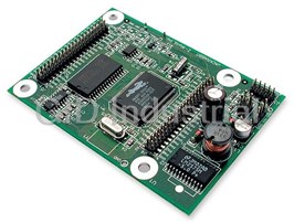
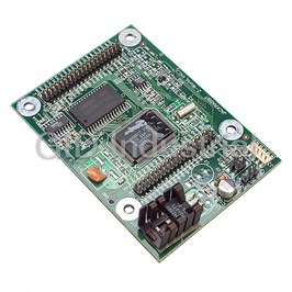
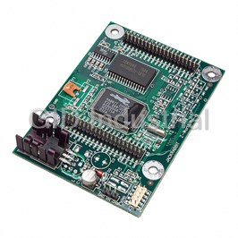
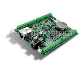


What they say about us
FANTASTIC RESOURCE
One of our top priorities is maintaining our business with precision, and we are constantly looking for affiliates that can help us achieve our goal. With the aid of GID Industrial, our obsolete product management has never been more efficient. They have been a great resource to our company, and have quickly become a go-to supplier on our list!
Bucher Emhart Glass
EXCELLENT SERVICE
With our strict fundamentals and high expectations, we were surprised when we came across GID Industrial and their competitive pricing. When we approached them with our issue, they were incredibly confident in being able to provide us with a seamless solution at the best price for us. GID Industrial quickly understood our needs and provided us with excellent service, as well as fully tested product to ensure what we received would be the right fit for our company.
Fuji
HARD TO FIND A BETTER PROVIDER
Our company provides services to aid in the manufacture of technological products, such as semiconductors and flat panel displays, and often searching for distributors of obsolete product we require can waste time and money. Finding GID Industrial proved to be a great asset to our company, with cost effective solutions and superior knowledge on all of their materials, it’d be hard to find a better provider of obsolete or hard to find products.
Applied Materials
CONSISTENTLY DELIVERS QUALITY SOLUTIONS
Over the years, the equipment used in our company becomes discontinued, but they’re still of great use to us and our customers. Once these products are no longer available through the manufacturer, finding a reliable, quick supplier is a necessity, and luckily for us, GID Industrial has provided the most trustworthy, quality solutions to our obsolete component needs.
Nidec Vamco
TERRIFIC RESOURCE
This company has been a terrific help to us (I work for Trican Well Service) in sourcing the Micron Ram Memory we needed for our Siemens computers. Great service! And great pricing! I know when the product is shipping and when it will arrive, all the way through the ordering process.
Trican Well Service
GO TO SOURCE
When I can't find an obsolete part, I first call GID and they'll come up with my parts every time. Great customer service and follow up as well. Scott emails me from time to time to touch base and see if we're having trouble finding something.....which is often with our 25 yr old equipment.
ConAgra Foods