

 Manufacturers
POWER-ONE RPM5QFQFKBS615
Description
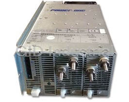
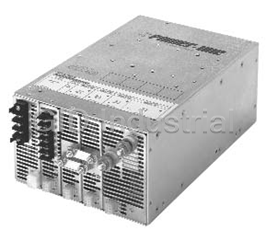
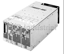
Power-One RPM5QFQFKBS615 Modular Industrial Power Supply, 3-Phase Input
Part Number
RPM5QFQFKBS615
Price
Request Quote
Manufacturer
POWER-ONE
Lead Time
Request Quote
Category
PRODUCTS - R
Features
- Active PFC models meet EN61000-3-2 and EN60555-2.
- Demonstrated DC output module MTBF of greater than 5 million hours.
- EN60950/UL1950 approved. CE Marked to the Low Voltage Directive.
- Metric mounting available on selected models.
- Modular construction; over 10 million configurations available.
- No minimum loads required on most outputs.
- Parallelable outputs with current sharing.
- Ruggedized AC input sections incorporate extensive transient protection.
- Single outputs fully regulated and isolated.
- System inhibit and individual module output inhibit capability.
- Up to 21 outputs per power supply from 1.0 to 48 VDC.
- Vibration tested at 6 GRMS, 3 axis, 10 to 2000 Hz.
Datasheet

Extracted Text
High Power Modular Products Data Sheet Description Table of Contents Power-One’s high power modular products can be Product Overview . . . . . . . . . . . . . . . . . . . . . . . . . . .2 configured to provide up to 21 outputs in over 10 Modular System Overview and Selection . . . . . . . . .4 million voltage and current combinations. Eighteen chassis are available from 1000 to 4000 watts; Configuring a Power System . . . . . . . . . . . . . . . . . . .5 including power factor corrected, three-phase input, and metric mounting hardware models. Over 90 DC Output Module Selection . . . . . . . . . . . . . . . . . . .6 output modules are available to provide voltages from Paralleled Module Configurations . . . . . . . . . . . . . . .8 1 to 48VDC. Output modules have a field demonstrated MTBF of greater than 5 million hours. DC Module Specifications . . . . . . . . . . . . . . . . . . . . .9 Other features include a comprehensive array of Chassis Electrical Specifications . . . . . . . . . . . . . . .11 module and system interface signals, extensive input transient protection, and international regulatory Exceptional AC Input Transient Immunity . . . . . . . .15 agency approvals. These high-performance products have a proven track record in high reliability DC Output Modules Demonstrated MTBF . . . . . . .17 communications, semiconductor test, and industrial applications. Modular High Power Mechanical Drawings (These may be downloaded from www.power-one.com by using the AC-DC Configurable Modular Link.) NUCLEAR AND MEDICAL APPLICATIONS - Power-One products are not designed, intended for use in, or authorized for use as critical components in life support systems, equipment used in hazardous environments, or nuclear control systems without the express written consent of the respective divisional president of Power-One, Inc. TECHNICAL REVISIONS - The appearance of products, including safety agency certifications pictured on labels, may change depending on the date manufactured. Specifications are subject to change without notice. REV. AUG 10, 2005 Page 1 of 19 www.power-one.com High Power Modular Products Data Sheet PRODUCT OVERVIEW RELIABILITY FLEXIBILITY PERFORMANCE • Demonstrated DC output module MTBFModular construction; over 10Single outputs fully regulated and of greater than 5 million hours. million configurations available. isolated. Ruggedized AC input sectionsUp to 21 outputs per power supplyActive PFC models meet EN61000-3-2 incorporate extensive transient protection. from 1.0 to 48 VDC. and EN60555-2. Vibration tested at 6 GRMS, 3 axis, Parallelable outputs with currentEN60950/UL1950 approved. CE 10 to 2000 Hz. sharing. Marked to the Low Voltage Directive. Two-year warranty.System inhibit and individual module No minimum loads required on most output inhibit capability. outputs. Metric mounting available on selected models. Modular High Power Series Product Overview METRIC MOUNTING SMF3 HMF3 HMF5 SMM3 SMM5 HMM5 HMM7 RMF5 RMM5 CHASSIS STANDARD SPF3 HPF3 HPF5 SPM3 SPM5 HPM5 HPM7 RPF5 RPM5 OUTPUT POWER AND POWER FACTOR .99 PFC to meet EN60555 YES YES YES N/A N/A N/A N/A YES N/A Max output wattage at high range line input 1350 2000 2000 1000 1500 2000 2500 3000 4000 Max output wattage at low range line input* 1000 1500 1500 1000 1500 N/A N/A N/A N/A INPUT VOLTAGE SPECIFICATIONS** High range VAC input 160-264 160-264 160-264 175-264 175-264 180-264 180-264 160-264 180-264 Low range VAC input 85-159 85-159 85-159 90-132 90-132 N/A N/A N/A N/A VAC input selection Wide Range Wide Range Wide Range Manual Manual N/A N/A N/A N/A VAC input phases Single Single Single Single Single Single Single Single Three OUTPUT MODULE SPECIFICATIONS Max # of outputs 9 9 15 9 15 15 21 15 15 # of module slots 335355755 MECHANICAL SPECIFICATIONS Chassis size H x W x L, inches 5 x 5.5 x 12.5 5 x 5.5 x12.5 5 x 8 x 11 5 x 5.5 x 11 5 x 8 x 11 5 x 8 x 11 5 x 11 x 13 5 x 8 x 12.5 5 x 8 x 15 Chassis size H x W, millimeters 127 x 140 127 x 140 127 x 203 127 x 140 127 x 203 127 x 203 127 x 280 127 x 203 127 x 203 Chassis size x L, millimeters x 318 x 318 x 280 x 280 x 280 x 280 x 330 x 318 x 381 INPUT TRANSIENT PROTECTION SPECIFICATIONS ESD Immunity Level 4 Level 4 Level 4 Level 4 Level 4 Level 4 Level 4 Level 4 Level 4 EN61000-4-2, 15kV/8kV15kV/8kV15kV/8kV15kV/8kV15kV/8kV15kV/8kV15kV/8kV15kV/8kV15kV/8kV RF Susceptibility Level 3 Level 3 Level 3 Level 3 Level 3 Level 3 Level 3 Level 3 Level 3 EN61000-4-3 10V/m 10V/m 10V/m 10V/m 10V/m 10V/m 10V/m 10V/m 10V/m Fast Transient/Burst Level 3 Level 3 Level 3 Level 3 Level 3 Level 3 Level 3 Level 3 Level 3 EN61000-4-4 +2kV +2kV +2kV +2kV +2kV +2kV +2kV +2kV +2kV Surge Immunity Class 4 Class 4 Class 4 Class 4 Class 4 Class 4 Class 4 Class 4 Class 4 EN61000-4-5 (Line-Line) 2kV 2kV 2kV 2kV 2kV 2kV 2kV 2kV 2kV Surge Immunity Class 4 Class 4 Class 4 Class 4 Class 4 Class 4 Class 4 Class 4 Class 4 EN61000-4-5 (line-Gnd) 4kV 4kV 4kV 4kV 4kV 4kV 4kV 4kV 4kV *Maximum wattage above 100VAC input for SPF/HPF REV. AUG 10, 2005 Page 2 of 19 www.power-one.com High Power Modular Products Data Sheet From 1000 to 4000 Watts Models with active Power Factor Correction (PFC) are EN61000-3-2 compliant SPM3/SMM3 SPM5/SMM5 SPF3/SMF3 1000 WATTS 1500 WATTS 1350 WATTS .99 PFC ACTIVE PFC HPF5/HMF5 HPF3/HMF3 HPM5/HMM5 2000 WATTS 2000 WATTS 2000 WATTS .99 PFC .99 PFC ACTIVE PFC ACTIVE PFC RPM5/RMM5 RPF5/RMF5 HPM7/HMM7 4000 WATTS 3000 WATTS 2500 WATTS 3 PHASE INPUT ACTIVE PFC PASSIVE PFC REV. AUG 10, 2005 Page 3 of 19 www.power-one.com High Power Modular Products Data Sheet MODULAR SYSTEM OVERVIEW AND SELECTION Selection Modular System Overview Power-One’s Modular High Power Series products are The modularity of these high power products allows the user to specify a power system configured from a wide configured with separate switch-mode DC output modules to provide the voltage and current ratings selection of standard off-the-shelf, plug-in modules. The power system is delivered completely assembled, burned required by each specific application. in, and tested. A part number comprised of a series The system is based on a 300 VDC system power bus designation, module listing, and options can be configured derived from either the AC utility line, or a user-supplied as follows: 300 VDC source. This 300 VDC bus provides the bulk 1. Choose a chassis based on required wattage, number DC required by each output module for conversion to its specified output voltage and current ratings. of outputs, and power factor. 2.Select modules following the guidelines in the As shown in the block diagram, this independent modular configuration section. approach provides complete isolation between the outputs, as well as all other system elements. Also, the 3. Decide on the options. Standard options are listed in the switching circuitry of each output module is clocked and configuration section. Please call the factory for special synchronized by the sync & bias supply section to reduce requirements, such as logic option cards. electrical interference between the outputs. ACTIVE RECTIFIER EMI AC INPUT SOFT & FILTER START FILTER 3 0 115/230 VAC SELECT 0 INRUSH LIMIT 300VDC DC OUTPUT MODULE #1 & INPUT V (OPTIONAL) POLARIZATION MOSFET RECTIFIER D DC OUTPUT #1 POWER & SWITCH FILTER C S MODULE Y CONTROL CONTROL S SIGNALS T SYNC & BIAS SUPPLY E DC OUTPUT MODULES #2, #3, #4, #5, #6 M OMITTED FOR CLARITY #1 RECTIFIER/FILTER & P DC OUTPUT MODULE #7 SYNC O MOSFET RECTIFIER W POWER & DC OUTPUT #7 BIAS SUPPLY RECTIFIER/FILTER & SYNC E SWITCH FILTER INVERTER CIRCUITS #2, #3, #4 R OMITTED FOR CLARITY B MODULE CONTROL U CONTROL RECTIFIER/FILTER SIGNALS S DC FAN #5 RECTIFIER/FILTER & SYNC SYSTEM SYSTEM CONTROL CONTROL SIGNALS REV. AUG 10, 2005 Page 4 of 19 www.power-one.com High Power Modular Products Data Sheet CONFIGURATION NOTES AND OPTIONS Configuration Notes • Not all modules can be used in all slots. Refer to the • Modules are designated left to right in the part number but compatibility table below. are installed right to left in the chassis. • Fill blank slots with K or L option. • Single and double wide modules occupy one and two chassis slots, respectively. Confirm that the total number of slots SLOT SLOT SLOT SLOTS required does not exceed the chassis slot capacity. #5 #4 #3 #2 & #1 EXAMPLE: OUTPUTS SELECTED 5V @ 150A 12V @ 20A –12V @ 20A INPUT K B1 B1 A2 SECTION All chassis slots are numbered in right-to-left sequence Standard Options INPUT POWER FAIL WARNING SYSTEM INHIBIT (OPT M, N & P) (OPT A, B & C) OTHER OPTIONS OPTION SIGNAL OUTPUT OPTION SIGNAL OUTPUT POWER OUTPUT DESCRIPTION OPTION INHIBIT ENABLE K – Single-Width Slot Blank Open Collector Hi To Lo Std N Conducts Std Logic Low Open Ckt. or L – Double-Width Slot Blank Transition To Give Signal Logic High See Paralleled Module Configurations on Page 8 for Additional Options A Logic High Open Ckt. or Logic Low B Open Ckt. Logic Low Open Collector or Logic High Lo To Hi M P Opens To Transition C Open Ckt. Give Signal Logic High or Logic Low Module and Chassis Compatibility slot compatibility of 1 in the slot closest to the input Confirm that the number listed in the compatibility column section, but can use any module with a compatibility number of four or less in the other two slots. Bold lines of the module selector guide is equal to or less than the lowest number specified for the module slots pictured designate adjoining slots that can be used for double wide modules. below. Example: The SPF3 can only use modules with a HPF5/HMF5/RPF5/RMF5 RPM5/RMM5 HPM7/HMM7 SPM3/SMM3 SPM5/SMM5/HPM5/HMM5 REV. AUG 10, 2005 Page 5 of 19 www.power-one.com High Power Modular Products Data Sheet MODULE SELECTOR GUIDE SINGLE VOLTAGE OUTPUT MODULES (For Preset Voltage Information, Consult Factory) NOMINAL ADJUSTMENT CURRENT (AMPS) SLOTS SLOT NOISE & RIPPLE (mV PK-PK) OUTPUT MODULE VOLTAGE RANGE @ 50°C (NOTE A) USED COMPATIBILITY TYPICAL/MAX (NOTE B) CONNECTION 1.5V 1.5 - 1.8V 35 T1 1 1 30/50 Type II 1.5V 1.5 - 1.8V 60 T6 1 1 30/50 Type I 1.5V 1.5 - 1.8V 250 T4 2 2 30/50 Type III 2V 1.8 - 2.2V 80 F8 1 3 25/40 Type I 2V 2 - 2.2V 35 F1 1 1 20/50 Type II 2V 2 - 2.2V 60 AG (Note C) 1 1 30/50 Type I 2V 2 - 2.2V 60 F6 1 1 30/50 Type I 2V 2 - 2.2V 150 F2 2 2 30/50 Type III 2V 2 - 2.2V 180 CS 2 5 30/50 Type III 2V 2 - 2.2V 250 F4 2 2 30/50 Type III 2V 2 - 2.2V 320 F7 2 5 30/100 Type III 2.3V 2.07 - 2.53 35 BJ 1 1 30/50 Type II 3.3V 2.97 - 3.63 35 H1 1 1 30/50 Type II 3.3V 2.97 - 3.63 60 H6 1 1 30/50 Type I 3.3V 2.97 - 3.63 80 H8 1 3 40/50 Type I 3.3V 2.97 - 3.63 90 DA 1 5 30/50 Type I 3.3V 2.97 - 3.63 150 H2 2 2 30/40 Type III 3.3V 2.97 - 3.63 250 H4 2 2 30/50 Type III 3.3V 2.97 - 3.63 320 H7 2 5 50/100 Type III 5V 4.5 - 5.5 35 A1 1 1 35/50 Type II 5V 4.5 - 5.5 60 A6 1 1 15/50 Type I 5V 4.5 - 5.5 80 A8 1 3 15/50 Type I 5V 4.5 - 5.5 90 DT 1 5 15/50 Type I 5V 4.5 - 5.5 150 A2 2 2 30/50 Type III 5V 4.5 - 5.5 220/250 A4 (Note D) 2 3/4 30/50 Type III 5V 4.5 - 5.5 320 A7 2 5 30/100 Type III 5V 4.5 - 5.5 375 QA 2 5 30/50 Type III 6V 5.4 - 6.6 35 AU 1 1 65/90 Type II 6V 5.4 - 6.6 80 FD 1 3 30/60 Type I 6V 5.4 - 6.6 100 CT 1 5 40/60 Type I 6V 5.4 - 6.6 120 BY 2 2 40/60 Type III 6V 5.4 - 6.6 250 CU 2 5 40/100 Type III 8V 7.2 - 8.8 65 AJ 2 2 53/80 Type III 8V 7.2 - 8.8 160 FA 2 5 40/200 Type III 8V 7.2 - 8.8 50 GM 1 4 40/60 Type I 8.5V 7.65 - 9.35 20 CF 1 1 50/75 Type II 10V 9 - 11 20 AW 1 1 66/100 Type II 10V 9 - 11 40 BE 1 3 40/60 Type I 10V 9 - 11 50 CV 1 5 66/100 Type I 10V 9 - 11 65 AQ 2 2 66/100 Type III 10V 9 - 11 160 CW 2 5 100/200 Type III 12V 10.8 - 13.2 20 B1 1 1 80/120 Type II 12V 10.8 - 13.2 40 B6 1 3 40/60 Type I 12V 10.8 - 13.2 50 B8 1 4 40/60 Type I 12V 10.8 - 13.2 65 B2 2 2 80/120 Type III 12V 10.8 - 13.2 80 BC 2 3 80/120 Type III 12V 10.8 - 13.2 135 DE 2 5 120/240 Type III 15V 13.5 - 16.5 16 AF (Note E) 1 1 15/35 Type II 15V 13.5 - 16.5 16 C1 1 1 100/150 Type II 15V 13.5 - 16.5 33 C6 1 3 30/60 Type I 15V 13.5 - 16.5 50 C5 1 5 100/150 Type I 15V 13.5 - 16.5 52 C2 2 2 100/150 Type III 18V 16.2 - 19.8 44 GD 1 4 80/120 Type I 24V 21.6 - 26.4 10 D1 1 1 160/240 Type II 24V 21.6 - 26.4 15 D6 1 2 80/120 Type II 24V 21.6 - 26.4 29 D8 1 4 70/110 Type I 24V 21.6 - 26.4 32 D2 2 2 160/240 Type III 24V 21.6 - 26.4 33 D5 1 5 60/100 Type I 24V 21.6 - 26.4 42 GH 1 5 50/100 Type I 28V 25.2 - 30.8 8.6 E1 1 1 200/280 Type II 28V 25.2 - 30.8 16 E7 (Note F) 1 1 50/100 Type I 28V 25.2 - 30.8 26 E8 1 4 70/100 Type I Modules that are highlighted in yellow or shaded are not recommended for new designs. REV. AUG 10, 2005 Page 6 of 19 www.power-one.com High Power Modular Products Data Sheet MODULE SELECTOR GUIDE SINGLE VOLTAGE OUTPUT MODULES (Continued) NOMINAL ADJUSTMENT CURRENT (AMPS) SLOTS SLOT NOISE & RIPPLE (mV PK-PK) OUTPUT MODULE VOLTAGE RANGE @ 50°C (NOTE A) USED COMPATIBILITY TYPICAL/MAX (NOTE B) CONNECTION 28V 25.2 - 30.8 27 E2 2 2 150/280 Type III 28V 25.2 - 30.8 29 E5 1 5 70/100 Type I 30V 27 - 33 8 EG 1 1 30/40 Type II 36V 32.4 - 39.6 20 J8 1 4 100/200 Type I 36V 32.4 - 39.6 21 J2 2 2 100/200 Type III 36V 32.4 - 39.6 23 J5 1 5 100/200 Type I 48V 43.2 - 52.8 5 G1 1 1 400/480 Type II 48V 43.2 - 52.8 12.5 G4 (Note E) 1 3 40/60 Type I 48V 43.2 - 52.8 16 G2 2 2 135/200 Type III 48V 43.2 - 52.8 16 G8 1 4 60/100 Type I 48V 43.2 - 52.8 19 G6 1 5 60/100 Type I WIDE-RANGE SINGLE OUTPUT, VARIABLE VOLTAGE MODULES NOMINAL ADJUSTMENT CURRENT (AMPS) SLOTS SLOT NOISE & RIPPLE (mV PK-PK) OUTPUT MODULE VOLTAGE RANGE @ 50°C (NOTE A) USED COMPATIBILITY TYPICAL/MAX (NOTE B) CONNECTION 1.0V 0.7 - 2.1V 320 ER 2 5 30/100 Type III 2.0V 1.5 - 2.8V 375 QF (Note C) 2 5 50/50 Type III 1.9V to 3V 1.9V to 3V 150 AB 2 2 50/50 Type III 3.3V 2.5V to 4V 375 QH 2 5 30/75 Type III 14V to 24V 14V to 24V 10 W1 1 1 80/120 Type II 14V to 24V 14V to 24V 32 BS 2 2 135/200 Type III DUAL VOLTAGE OUTPUT MODULES NOMINAL CURRENT (AMPS) SLOTS SLOT NOISE & RIPPLE (mV PK-PK) OUTPUT MODULE VOLTAGE @ 50°C (NOTE A) USED COMPATIBILITY TYPICAL/MAX (NOTE B) CONNECTION 12/12 10/4 M4 (Note G) 1 1 120/240 Type II ±12 10/10 B4 (Note H) 1 1 120/240 Type II ±15 8/8 C4 (Note H) 1 1 150/300 Type II ±20 5/5 BQ (Note H) 1 1 80/100 Type II ±24 5/5 D4 (Note H) 1 1 80/120 Type II TRIPLE OUTPUT VOLTAGE MODULES (Note G) NOMINAL CURRENT (AMPS) SLOTS SLOT NOISE & RIPPLE (mV PK-PK) OUTPUT MODULE VOLTAGE @ 50°C (NOTE A) USED COMPATIBILITY MAXIMUM (NOTE B) CONNECTION 5/1.5/3.3 15/10/10 FC 1 1 100/100/100 Type II 5/1.5/12 10/10/10 CA 1 1 100/100/120 Type II 5/2.2/12 10/10/10 W6 1 1 100/100/120 Type II 5/12/12 10/10/10 M6 1 1 50/120/120 Type II 5.2/12/12 15/8/8 BA 1 1 100/180/180 Type II 5.2/12/12 5/16/7 AE 1 1 60/160/120 Type II 5/12/24 10/10/5 U6 1 1 50/120/240 Type II 5/15/15 10/8/8 V6 1 1 50/150/150 Type II 5/24/24 10/5/5 R6 1 1 50/240/240 Type II 12/12/12 10/10/10 N6 1 1 120/120/120 Type II 5/15/12 10/8/10 EC 1 1 50/150/120 Type II 24/12/12 5/10/10 P6 1 1 240/120/120 Type II NOTES: A) For ambient temperatures above 50 °C, output current must be linearly derated to 50% at the maximum operational ambient temperature, 70 °C. B) The output noise and ripple measurement is bandwidth limited to 20 MHz. C) Module is designed to accommodate output cable losses of up to one volt. D) A4 module provides 220A in chassis with slot compatibility rating of 3, and 250A in chassis with slot compatibility rating of 4. E) Module is designed for use in applications demanding low noise and ripple. Consult factory for further specifications. F) Not to be used with SPM2 and SPM3 chassis. G) All triple output modules, as well as the M4 dual-output module, have floating outputs. Like voltages may be shared within the same module. All triple output adjustments and interface signals are for output #1. Consult factory for more information. H) The dedicated negative (-) output is quasi-regulated. Both outputs require a small minimum load to perform to specification. Consult factory for more information. Modules that are highlighted in yellow or shaded are not recommended for new designs. REV. AUG 10, 2005 Page 7 of 19 www.power-one.com High Power Modular Products Data Sheet PARALLELED MODULE CONFIGURATIONS Single output, similar-voltage output modules can be configured for parallel operation to provide output currents up to 840 amps. Factory standard paralleling suffixes are shown below. All paralleling suffixes include factory-installed bus bars and internally-connected current sharing. Please consult factory for paralleling configurations not shown. • Choose appropriate chassis and modules as described in the Selection and Configuration Notes sections. • Select the required output connection type as shown in the Module Selector Guide. • Select the paralleling suffix that corresponds to the selected output modules. (The paralleling suffix follows after all other option codes.) CHASSIS CHASSIS SLOT PARALLELING 7 6 5 4 3 2 1 SUFFIX EXAMPLE: REQUIREMENT: 5V @ 300A 3 SLOT CHASSIS: SPM3, SMM3 II YA Select Chassis: HPF3 SPF3, SMF3 III YBSelect Modules: A4 (5V @ 250A), A6 (5V @ 60A) HPF3, HMF3 II I I YCChoose Corresponding Paralleling Suffix: YD Final Part Number: HPF3A4A6YD I III YD II III YE LIMITATIONS FOR STANDARD PARALLELING SYSTEM 5 SLOT CHASSIS: SPM5, SMM5 II YF Single output modules only HPM5, HMM5 III YGRipple and noise limit will be 20% N/U HPF5, HMF5 I II YJ over the largest value paralleled For paralleling modules over 320A, RPM5, RMM5 I III YJ consult factory RPF5, RMF5 II I III YM I I III YN OUTPUT CONNECTIONS I III YP Type I = #10-32 studs III III YH Type II = Barrier Block II III III YR Type III = 5/16"-18 studs I III III YS 7 SLOT CHASSIS: HPM7, HMM7 II YF III YG N/U I II YJ I III YJ I I III YN I III YP III III YH I III III YS III III III YT REV. AUG 10, 2005 Page 8 of 19 www.power-one.com High Power Modular Products Data Sheet DC OUTPUT MODULE SPECIFICATIONS SINGLE AND DUAL OUTPUT MODULES PARAMETER CONDITIONS/DESCRIPTION MIN NOM MAX UNITS Output Voltage Adjustment Range (V2 output is not adjustable) -10 +10 % Output Current At 0°C to 50°C ambient. See Module Selector Guide. Ambient Temperature Range 100% rated load. 0 50 °C Derated linearly to 50% load. 0 70 Initial Voltage Setting Factory set V1 output -1 +1 % Output Voltage Adjustment V1 output -10 +10 % Margining/Remote Range (provided for V1 output only). -10 +10 % Voltage Adjustment Programming sensitivity from 2.0V (provided for V1 output only). -4 -5 -6 %/V Remote Voltage Sense Total cable drop (provided for V1 output only). 0.5 V Temperature Coefficient At 0°C to 50°C ambient. 0.01 0.02 %/°C Long-term Voltage Drift 1000 hours. 0.1% Line Regulation Over input operating range. 0.05 0.1 % 5 Volt Modules Load Regulation 0% to 100% load with remote sense. < 10 mV Single Output Modules 0% to 100% load without remote sense. < 60 mV Consult Factory For > 5 Volt Modules Specific Ratings 0% to 100% load with remote sense. < 30 mV 0% to 100% load without remote sense. < 75 mV Cross Regulation Between Single 0% to 100% load change. 0 % Output Modules in One Chassis Load Regulation, Dual Output Modules Positive Output 0% to 100% load with remote sense. < 30 mV 0% to 100% load without remote sense. < 75 mV Load Regulation, Dual Output Modules Negative Output 0% to 100% load. 5 % Cross Regulation, Dual Output Modules Positive Output 0% to 100% load change. 0.1 mV Cross Regulation, Dual Output Modules Negative Output 10% to 100% load change. 5 % Minimum Load Current Dual output modules only. See factory data sheets. 1 Amp Current Limit Factory set. As a % of full rated Io. Dual output modules use 110% 115% 120% Amp primary power limiting. See module ratings. Short Circuit Current As a % of full rated Io. 100% Amp Current Sharing Current sharing accuracy as a % of full rated Io. (V1 output) 1 % Overvoltage Protection (V1 output) Trip point as a % of V0 for V0 equal to or greater than 5V. 115% 120% 125% V Resettable by recycling input. Reverse Polarity Protection Reverse current as a % of full rated Io. Reverse voltage externally applied. 100% Amp Logic LO = off 0.9 V Inhibit Sink current. 0.4 mA Logic HI = on 2 V Source current. 20 µA Logic LO (when V0 deviates ±3% to ±5% from adjusted set point). 0.9 V Output Good Signal (V1 output) Sink current. 40 mA Logic HI (with internal pull-up to 5V). 1.5 k� Noise and Ripple 20 MHz bandwith. See module ratings. mVPP Transient Response For V0 equal to or greater than 5V, 75% to 100% load step. 2% mVPK 50% to 100% load step. 4% Recovering to 1% within 400 µSec, Slew rate = 1A/µSec. Turn-On Delay After input applied. 1 Sec After inhibit released. 50 ms Rise Time 5% to 95% of V0. 50 ms Overshoot Overshoot as a % of V0 at turn-on. 0% V Turn-Off Delay After inhibit or OVP trip. 500 µs Specifications in this section are general and may vary according to specific modules. REV. AUG 10, 2005 Page 9 of 19 www.power-one.com High Power Modular Products Data Sheet DC OUTPUT MODULE SPECIFICATIONS TRIPLE OUTPUT MODULES PARAMETER CONDITIONS/DESCRIPTION OUTPUT #1 OUTPUT #2 OUTPUT #3 MIN. NOM. MAX MIN. NOM. MAX MIN. NOM. MAX UNITS Output Current At 0°C to 50°C ambient. See module ratings. Ambient Temperature Range 100% rated load. 0 50 0 50 0 50 °C Derated linearly to 50% load. 70 70 70 Initial Voltage Setting Initial voltage set point as a % of V0. -1% +1% -1% +1% -1% +1% V Output Voltage Adjustment Range -10% +10% -10% +10% -10% +10% V Margining/Remote Range. -10% +10% V Voltage Adjustment Programming sensitivity, from 2.5V. -4 -5 -6 %/V Remote Voltage Sense Total cable drop. 0.5 V Temperature Coefficient At 0°C to 50°C ambient. 0.01 0.02 0.01 0.02 0.01 0.02 %/°C Long Term Voltage Drift 1000 hours. 0.1% 0.1% 0.1% Line Regulation Over input operating range. 0.05 0.1 0.05 0.1 0.05 0.1 % 0% to 100% load w/remote sense 0.1 0.2 % Load Regulation 0% to 100% load w/o remote sense (Note 1) 1 5 1 5 1 5 mV/Amp Cross Regulation 0% to 100% load change. 0 0 0 % Minimum Load Current 0 0 0 Amp Current Limit Factory set. As a % of full rated Io. 105% 120% 105% 120% 105% 120% Amp Short Circuit Current As a % of full rated Io. 100% 100% 100% Amp Current Sharing (Note 2) Current sharing accuracy as a % of 5 5 5 % full rated Io. Factory calibrated at 100% load. Reverse Voltage Protection Reverse current as a % of full rated 100% 100% 100% Amp Io. Reverse voltage externally applied. Logic LO = off 0.4 V Sink current. 0.4 mA Inhibit Logic HI = on 2.5 V Source current. 20 µA Logic LO upon current limit detection, OVP, or shut down. Output Fault Signal Logic LO (with 3 mA sink). 0.7 0.7 0.7 V Logic HI (internal pull-up to 5V) 1.5 1.5 1.5 k� Turn-On Delay After input applied. 1 1 1 Sec After inhibit released. 50 50 50 ms Rise Time 5% to 95% of V0.505050ms Overshoot Overshoot as a % of V0.3% 3%3%V Turn-Off Delay After inhibit or OVP trip. 500 500 500 µs Overvoltage Protection Provided on output #1 only. 5V Output: 130%, ±5% of V0. Trip point as a % of V0. 12V Output: 120%, ±5% of V0. Resettable by recycling input. 24V Output: 115%, ±5% of V0. Output Voltage V0 5V 12V 15V 24V 20 MHz bandwidth. NOM. 65 80 100 160 Noise and Ripple mVPP MAX. 100 120 150 240 NOM. 20 20 25 40 200 MHz bandwidth. mVRMS MAX. 30 30 38 60 Output Voltage V0 5V 12V 15V 24V 75% to 100% load change @ 0.4A/µs. 150 240 240 480 Transient Response mVPP 50% to 100% load change @ 0.4A/µs. 300 480 480 960 Recovery to 1% within 400 µs. NOTES: 1) 20 mV max below 5% load. 2) Identical voltages can be paralleled at the factory. Please consult the factory. REV. AUG 10, 2005 Page 10 of 19 www.power-one.com High Power Modular Products Data Sheet CHASSIS SPECIFICATIONS: SPF3 / SMF3* HPF3 / HMF3* HPF5 / HMF5* RPF5 / RMF5* INPUT PARAMETER CONDITIONS MIN. NOM. MAX. UNITS Input Voltage AC Input 85 264 VAC �=70% 115 VAC; 1000W 12.8 115 VAC; 1300W 16.2 ARMS Input Current 115 VAC; 1500W 19.2 230 VAC; 1350W 8.6 230 VAC; 1500W 9.6 230 VAC; 2000W 12.8 230 VAC; 3000W 19.0 85 - 264 VAC; >500W (SPF3, HPF3, HPF5) 0.98 Power Factor W/VA 180 - 264 VAC; >750W (RPF5) 0.98 Inrush Surge Current Vin = 132VAC (one cycle) 20 APK Vin = 264VAC (one cycle) 40 Input Frequency AC Input 47 63 Hz Start Up Time From time AC is applied to Vout is in regulation 1.5 Sec Hold-up Time 85 - 264 VAC at rated maximum power 23 ms Input Power Fail Warning Logic signal time before regulation dropout due to loss of input power 5 ms Overtemperature Warning Advance warning before shutdown 10 ms SAFETY AND EMI UL1950 Agency Approvals CSA 22.2 No. 950 EN60950 (TÜV) Line Harmonic Disturbance EN60555-2 EN61000-3-2 Dielectric Withstand Voltage Input to Output (“Y” capacitors disconnected) 4300 Input to Chassis 2300 VDC Output to Chassis 500 Leakage Current Per UL1950 and CSA 22.2 No. 950 1.5 mA Per EN60950 2.5 Electromagnetic Interference FCC CFR title 47 Part 15, Sub-Part B Conducted Level A EN55022 / CISPR 22, Conducted GENERAL SPF3 Full Load, 85-100 VAC input 875 SPF3 Full Load, 101-159 VAC input 1000 SPF3 Full Load, 160-264 VAC input 1350 Output Power Watts HPF3/HPF5 Full Load, 85-100 VAC input 1300 HPF3/HPF5 Full Load, 101-159 VAC input 1500 HPF3/HPF5 Full Load, 160-264 VAC input 2000 RPF5 Full Load, 160-264 VAC input 3000 Efficiency Full Load, Nominal Line Input 75 % Vibration Random Vibration, 10 Hz to 2 kHz, 3 axis 6 GRMS Shock Operating, peak acceleration 20 GPK Operating Temperature At 100% load 0 50 °C Derate linearly above 50°C to 50% 70 Storage Temperature -40 85 °C Altitude Operating 10,000 Feet Non-Operating 50,000 Relative Humidity Non-Condensing 95 % Acoustical Noise “A” Weighted @ 1 meter 50 dB Cooling Static pressure through system enclosure 0.05 In of H O 2 *Metric mounting chassis meet all specifications of non-metric models. REV. AUG 10, 2005 Page 11 of 19 www.power-one.com High Power Modular Products Data Sheet CHASSIS SPECIFICATIONS: SPM3 / SMM3* INPUT PARAMETER CONDITIONS MIN. NOM. MAX. UNITS AC Input Low range 90 115 132 VAC Input Voltage High range 175 230 264 VAC DC Input 250 300 350 VDC 1000 Watt Load Vin = 90 VAC 25 ARMS Input Current Vin = 175 VAC 13 ARMS Vin = 250 VDC 3 ADC SPM3 Inrush Surge Current Vin = 132 VAC 19 APK Vin = 264 VAC 38 Input Frequency With AC Input 47 440 Hz Hold-up Time After last AC line peak with 115/230 VAC Input 23 ms Input Power Fail Warning Logic signal before regulation ms 5 dropout due to loss of input power Overtemperature Shutdown System shutdown due to excessive 75 85 °C internal temperature Thermal Warning Advanced warning before overtemperature shutdown 10 ms SAFETY AND EMI UL1950 Agency Approvals CSA22.2 #950 EN60950 (TÜV) Input to Output 4300 Dielectric Withstand Voltage Input to Chassis 2300 VDC Output to Chassis 500 Input to Output 10 Insulation Resistance Input to Chassis 10 M� Output to Chassis 2 Leakage Current SPM3 1.75/1.25 mA Primary to Secondary 8 Safety Spacing mm Primary to Chassis 4 Electromagnetic FCC CFR title 47 Part 15, Sub-Part B Conducted Level A Interference EN55022 / CISPR 22, Conducted GENERAL Output Power (Max) SPM3 1000 Watts Efficiency Full load, typical modules. 75 % Power Factor 115/230 VAC input 0.7 W/VA Vibration Random vibration from 10Hz to 2 kHz, (3 axis) 6.0 GRMS Shock Operating: peak acceleration 20 GPK At 100% Load 50 Operating Temp. 0 ÞC Derate to 50% at 70ÞC 70 Storage Temp. –40 85 ÞC Operating 10,000 Feet Altitude (Consult factory for operation above 10,000 feet) Non-operating 50,000 Feet Relative Humidity Non-condensing 95 % Acoustical Noise “A” weighted, anechoic at 1 meter 50 dB Cooling Internal Fan Cooled (At Sea Level) 50 CFM *Metric mounting chassis meet all specifications of non-metric models. REV. AUG 10, 2005 Page 12 of 19 www.power-one.com High Power Modular Products Data Sheet CHASSIS SPECIFICATIONS: SPM5 / SMM5* HPM5 / HMM5* HPM7 / HMM7* INPUT PARAMETER CONDITIONS MIN. NOM. MAX. UNITS AC Input Low range-SPM5 only 90 115 132 VAC Input Voltage High range 175 230 264 VAC HPM5/HPM7 Operate Only On High Range DC Input DC Input Range 250 300 350 VDC Vin = 90 VAC 2 ARMS/100 Watts Load Input Current Vin = 175 VAC 1 ARMS/100 Watts Load Vin = 250 VDC 0.53 ADC/100 Watts Load Vin = 132 VAC 19 Inrush Surge Current APK Vin = 264 VAC 38 Input Frequency With AC Input 47 440 Hz After last AC line peak with Hold-up Time ms 30 115/230 VAC Input Logic signal before regulation Input Power Fail Warning ms 3 dropout due to loss of input power Thermal Warning Warning before overtemperature shutdown 10 ms SAFETY AND EMI UL1950 Agency Approvals CSA22.2 #950 EN60950 (TÜV) Input to Output 4300 Dielectric Withstand Input to Chassis 2300 VDC Voltage Output to Chassis 500 Input to Output 10 Insulation Resistance Input to Chassis 10 M� Output to Chassis 10 Leakage Current Per UL1950 and CSA 22.2 No. 950 1.5 mA Per EN60950 2.5 Primary to Secondary 8 Safety Spacing mm Primary to Chassis 4 Electromagnetic FCC CFR Title 47 Part 15, Sub-Part B Conducted Level A Interference EN55022 / CISPR 22, Conducted GENERAL Output Power (Max) - SPM5/HPM5/HPM7 1500/2000/2500 Watts Efficiency Full Load 75 % Power Factor 115/230 VAC input, typical modules. 0.7 W/VA MIL-STD-810D, Method 514.3, Vibration 6GRMS Category I, Proc I MIL-STD-810D, Method 516.3, Shock 20 GPK Proc II, IV, VI At 100% Load 50 Operating Temp. 0 ÞC Derate to 50% at 70ÞC 70 Storage Temp. -40 85 ÞC Operating (Consult factory for operation Altitude above 10,000 feet) 10,000 Feet Non-operating 50,000 Feet Relative Humidity Non-condensing 95 % Acoustical Noise “A” weighted, anechoic at 1 meter 50 dB Cooling Internal Fan 80 CFM *Metric mounting chassis meet all specifications of non-metric models. REV. AUG 10, 2005 Page 13 of 19 www.power-one.com High Power Modular Products Data Sheet CHASSIS SPECIFICATIONS: RPM5 / RMM5* INPUT PARAMETER CONDITIONS MIN. NOM. MAX. UNITS Input Voltage** AC Input Three Phase with Ground Phase-to-Phase 180 230 264 VAC DC Input 250 300 350 VDC 180 VAC 23 208 VAC 20 ARMS Input Current 220 VAC 19 250 VDC 23 ADC Inrush Surge Current Vin = 264 VAC (one cycle) 38 APK Input Frequency With AC Input 47 63 Hz Hold-up Time After last AC line peak 208 VAC 20 ms 220 VAC 25 Input Power Fail Warning Logic signal before regulation ms 5 dropout due to loss of input power Overtemperature Shutdown System shutdown due to excessive 70 80 °C internal temperature Thermal Warning Advanced warning before shutdown 10 ms SAFETY AND EMI UL1950 Agency Approvals CSA 22.2 No. 950 EN60950 (TÜV) Input to Output 4300 Dielectric Withstand Voltage Input to Chassis 2300 VDC Output to Chassis 300 Input to Output 10 Insulation Resistance Input to Chassis 10 M� Output to Chassis 2 Leakage Current Per UL1950 and CSA 22.2 No. 950 1.5 mA Per EN60950 2.5 Electromagnetic FCC CFR title 47 Part 15, Sub-Part B Conducted Level A Interference with 3-phase input and EN55022/CISPR 22, Conducted no external filtering GENERAL Output Power*** Full Load, 230 VAC 4000 Watts Efficiency Full Load, 230 VAC 75 % Power Factor > 2000 watts @ 60 Hz, > 3000 watts 0.9 W/VA @ 50 Hz with 3-phase input Vibration Random vibration from 10Hz to 2 KHz, (3 axis) 6 GRMS Shock Operating, peak acceleration 20 GPK At 100% Load 50 Operating Temp. 0 ÞC Derate linearly above 50°C to 50% 70 Storage Temp. –40 85 ÞC Altitude Operating 10,000 Feet Non-operating 50,000 Relative Humidity Non-condensing 95 % Acoustical Noise “A” weighted at 1 meter 60 dB Cooling Static pressure through system closure 0.05 In of H 0 2 *Metric mounting chassis meet all specifications of non-metric models. ** For single-phase operation, please consult factory. *** 2800W, MAX with single-phase, 180 - 264VAC. Consult factory. REV. AUG 10, 2005 Page 14 of 19 www.power-one.com High Power Modular Products Data Sheet EXCEPTIONAL AC INPUT TRANSIENT IMMUNITY Initial Analysis Power-One has been working with customers to improve our high power products for over ten years. Because these products are often used in industrial environments, some of our customers were concerned with AC input transient immunity. This prompted us to implement an extensive data collection and analysis project which provided the following information: 1) AC input monitoring data taken at end-users (our customers’ customers) sites revealed extreme input transients with differential transients beyond the highest levels, and longest durations, of the new ISO1000/EN61000-4-5 specification. 2) A review of our failure analysis database revealed primary-side component failures which appeared t be caused by excessive input transients. In addition, some customers reported similar failures with high power products manufactured by companies other than Power-One. 3) The AC input monitoring data, mentioned in item #1, was used as a starting point in engineering lab testing and Spice modeling. Both methodologies confirmed the failure modes mentioned in item #2. Other Factors Given the very high demonstrated MTBF hours of the DC output modules, failures that were thought to be caused by AC input line transients became a significant percentage of overall customer returns. Therefore, the plan to enhance overall reliability included increasing the robustness of the AC input section. We found that AC input transient immunity is most critical to equipment that is not powered from a standard 115VAC wall socket, and where line impedances (resistive and inductive) are relatively high, and aid in the absorption of transient line conditions. Experience has also shown that the primary cause of damage is differential voltage events (between the lines), not common mode (between line(s) and ground). REV. AUG 10, 2005 Page 15 of 19 www.power-one.com High Power Modular Products Data Sheet EXCEPTIONAL AC INPUT TRANSIENT IMMUNITY Improvements Enhancing the input board design was accomplished by specifying oversized input components and adding Metal Oxide Varistors (MOV’s) to protect against both common and differential-mode transients. Before putting the enhanced input board into production, an extensive qualification program was performed which confirmed that the following standards were exceeded: Specification Description Classification Volts EN61000-4-2 ESD Immunity Level 4 8kV EN61000-4-3 RF Susceptibility Level 3 10V/m EN61000-4-4 Fast Transient/Burst Immunity Level 3 4kV EN61000-4-5 Surge Immunity Common-mode Class 4 4kV Differential-mode Class 4 2kV It is important to note that these are the most stringent levels of each of these specifications. In the case of the critical differential surge immunity level, Power-One’s internal design and test levels for high power products are over twice the maximum specification level shown above. Field Data Results The field data results were impressive. After a year, and over 10,000 units shipped with enhanced AC input sections, our customers have not returned any products that were diagnosed to have AC input transient related failures. This clearly shows that we have significantly improved the field reliability of our high power products and have set a new standard in the industry for AC input transient immunity. To complement the robustness of the AC input chassis, the DC output modules have a demonstrated MTBF of over 5 million hours. The next three pages describe how the exceptional MTBF of the DC output modules also contributes to making Power-One’s high power products the most reliable in the industry. REV. AUG 10, 2005 Page 16 of 19 www.power-one.com High Power Modular Products Data Sheet DC OUTPUT MODULES DEMONSTRATED MTBF OF 5 MILLION HOURS Overview This report summarizes the methodology, calculations, and results that were used to document the field reliability of standard high power product modules (non-RPM5), and to predict the reliability of the enhanced performance high density modules for the 4,000 Watt RPM5 Series power supply. Based on this data, the typical output module demonstrated MTBF is five million hours with an ambient temperature of 25 °C. Basis for Prediction At the beginning of 1996, Power-One initiated the design of the 4,000 Watt RPM5. This design project produced one of the highest power density AC/DC power supplies in the industry. To support this program, Power-One started an extensive effort to update field reliability information for existing (non-RPM5) modules. In addition to quantifying the reliability for these modules, this information was also used as the basis for predicting the reliability of the new high density RPM5 module designs. Power-One created a 33-page proprietary report analyzing the field history (by power supply, by module), utilizing years of data. The customer’s end-product used in this report operated 24 hours per day, 7 days per week, and accumulated over 140 million unit-hours of field data for this analysis. In addition, three years of field failure data were gathered from Power-One’s on-line failure analysis database. Power-One believes this actual demonstrated field history is more valuable and provides a more realistic reliability estimation than that represented by the theoretical calculated predictions of MIL-HDBK-217 or Bellcore TR-332. Methodology The minimum and maximum MTBF (80% confidence level) was established by applying the Chi-Squared method to the collected data. To improve the usefulness of the results in the original report, this report includes similar modules (same/similar PCB and mechanical structure). In the case of the RPM5 Series modules, the respective base module data was used as a starting point and was then modified to reflect new stress levels, new components, modified cooling, etc. Results The data on the following pages present the resulting field reliability of 48 modules. This data includes minimum and maximum 9 FITs (Failures In Time - 10 hours) and MTBF at 25 °C for each of the modules. Vibration testing is performed in three orthogonal axis from 10 to 2000 Hz, at 6.15 GRMS as part of STRIFE testing. Thermal shock testing includes a 15 °C per minute ramp rate from -30 °C to +80 °C while input power is cycled and outputs are driven to full- rated load. This is also a part of STRIFE testing. REV. AUG 10, 2005 Page 17 of 19 www.power-one.com High Power Modular Products Data Sheet DC OUTPUT MODULES DEMONSTRATED MTBF OF 5 MILLION HOURS Details of MTBF Information Please refer to the table on the following page for MTBF data for specific modules. Field data included: 3 year shipment history • 19 unique power supply configurations • 21 types of output modules • 4 million to 71 million operating hours • for individual modules Data adjustments were objectively made to: Eliminate customer induced and other similar failures • Provide for confidence factors (80%) • Eliminate non-operating time prior to installation • Group similar modules with similar failure • rates to improve accuracy of data Make minor extrapolations for modules that • Computer Aided Design (CAD) had minor technical variations from subject modules provides thermal modeling, vibration analysis, and circuit simulation data before a prototype is built. Extensive use of computer-based modeling programs contributes to reliability. Power-One’s modular products have been proven in high-reliability communications and semiconductor test equipment applications. REV. AUG 10, 2005 Page 18 of 19 www.power-one.com High Power Modular Products Data Sheet REV. AUG 10, 2005 Page 19 of 19 www.power-one.com High Power DC Output Module Reliability Based Upon 140,000,000 Unit-Hours of Field Data 9 FITS (Failures/10 Hours) MTBF (millions of Hours) 25°C AMBIENT 25°C AMBIENT MODULE WIDTH TYPE MINIMUM MAXIMUM MINIMUM MAXIMUM A1 Single Standard 117 254 3.94 8.55 A2 Double Standard 139 205 4.88 7.19 A4 Double Standard 139 205 4.88 7.19 A6 Single Standard 117 254 3.94 8.55 A7 Double High Density 185 273 3.66 5.41 A8 Single Standard 117 254 3.94 8.55 AB Double Standard 139 205 4.88 7.19 AG Single Standard 117 254 3.94 8.55 AJ Double Standard 139 205 4.88 7.19 AQ Double Standard 139 205 4.88 7.19 AU Single Standard 117 254 3.94 8.55 B1 Single Standard 117 254 3.94 8.55 B2 Double Standard 139 205 4.88 7.19 B4 Single Standard 117 254 3.94 8.55 B6 Single Standard 117 254 3.94 8.55 BC Double Standard 139 205 4.88 7.19 BE Single Standard 117 254 3.94 8.55 BJ Single Standard 117 254 3.94 8.55 BQ Single Standard 117 254 3.94 8.55 C1 Single Standard 117 254 3.94 8.55 C2 Double Standard 139 205 4.88 7.19 C4 Single Standard 117 254 3.94 8.55 C5 Single High Density 156 338 2.96 6.41 C6 Single Standard 117 254 3.94 8.55 CS Double Standard 139 205 4.88 7.19 CT Single Standard 117 254 3.94 8.55 CU Double High Density 185 273 3.66 5.41 CV Single Standard 117 254 3.94 8.55 CW Double High Density 185 273 3.66 5.41 D1 Single Standard 117 254 3.94 8.55 D4 Single Standard 117 254 3.94 8.55 D5 Single High Density 156 338 2.96 6.41 DA Single Standard 117 254 3.94 8.55 DE Double High Density 185 273 3.66 5.41 E1 Single Standard 117 254 3.94 8.55 E5 Single High Density 156 338 2.96 6.41 F1 Single Standard 117 254 3.94 8.55 F2 Double Standard 139 205 4.88 7.19 F4 Double Standard 139 205 4.88 7.19 F6 Single Standard 117 254 3.94 8.55 F7 Double High Density 139 205 4.88 7.19 G1 Single Standard 117 254 3.94 8.55 G4 Single Standard 117 254 3.94 8.55 H1 Single Standard 117 254 3.94 8.55 H2 Double Standard 139 205 4.88 7.19 H4 Double Standard 139 205 4.88 7.19 H6 Single Standard 117 254 3.94 8.55 H7 Double High Density 185 273 3.66 5.41
Frequently asked questions
What makes Elite.Parts unique?

What kind of warranty will the RPM5QFQFKBS615 have?
Which carriers does Elite.Parts work with?
Will Elite.Parts sell to me even though I live outside the USA?
I have a preferred payment method. Will Elite.Parts accept it?


What they say about us
FANTASTIC RESOURCE
One of our top priorities is maintaining our business with precision, and we are constantly looking for affiliates that can help us achieve our goal. With the aid of GID Industrial, our obsolete product management has never been more efficient. They have been a great resource to our company, and have quickly become a go-to supplier on our list!
Bucher Emhart Glass
EXCELLENT SERVICE
With our strict fundamentals and high expectations, we were surprised when we came across GID Industrial and their competitive pricing. When we approached them with our issue, they were incredibly confident in being able to provide us with a seamless solution at the best price for us. GID Industrial quickly understood our needs and provided us with excellent service, as well as fully tested product to ensure what we received would be the right fit for our company.
Fuji
HARD TO FIND A BETTER PROVIDER
Our company provides services to aid in the manufacture of technological products, such as semiconductors and flat panel displays, and often searching for distributors of obsolete product we require can waste time and money. Finding GID Industrial proved to be a great asset to our company, with cost effective solutions and superior knowledge on all of their materials, it’d be hard to find a better provider of obsolete or hard to find products.
Applied Materials
CONSISTENTLY DELIVERS QUALITY SOLUTIONS
Over the years, the equipment used in our company becomes discontinued, but they’re still of great use to us and our customers. Once these products are no longer available through the manufacturer, finding a reliable, quick supplier is a necessity, and luckily for us, GID Industrial has provided the most trustworthy, quality solutions to our obsolete component needs.
Nidec Vamco
TERRIFIC RESOURCE
This company has been a terrific help to us (I work for Trican Well Service) in sourcing the Micron Ram Memory we needed for our Siemens computers. Great service! And great pricing! I know when the product is shipping and when it will arrive, all the way through the ordering process.
Trican Well Service
GO TO SOURCE
When I can't find an obsolete part, I first call GID and they'll come up with my parts every time. Great customer service and follow up as well. Scott emails me from time to time to touch base and see if we're having trouble finding something.....which is often with our 25 yr old equipment.
ConAgra Foods