

 Manufacturers
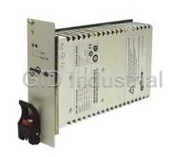
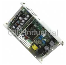
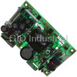
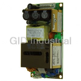
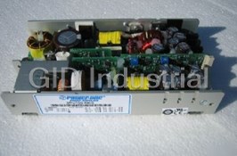
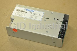
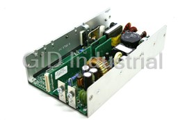
POWER-ONE CPD250-4530
Description
Power One CPD250-4530 Power Supply. 5, 3.3, 12, -12 V | 250 W | 82.2 % typ. Eff. | Case Size: 3U x 8HP
Part Number
CPD250-4530
Price
Request Quote
Manufacturer
POWER-ONE
Lead Time
Request Quote
Category
POWER SUPPLY
Specifications
Chassis
3U x 8HP
Efficiency
80%min, 82.2%typ
Input Range
36 (48) 75VDC
Options
L: Output Current Latch, A: Face Plate without Logo, C: Protective Lacquer, G: RoHS
Output Vo1
5V, 25A (40max)
Output Vo2
3.3V, 20A (40max)
Output Vo3
12V, 4A (5.5max)
Output Vo4
-12V, 1A (2max)
Output W
250W
Features
- 4 high current outputs with flexible load distribution
- 47 pin connector, type Positronic
- Compliant to PICMG® CompactPCI® specifications
- Extremely high efficiency and high power density
- Hot-swap capability
- Inhibit and enable inputs
- Integrated ORing FETs / diodes for true redundancy
- Low inrush current
- Overtemperature, overvoltage, overcurrent, and overpower protection
- Remote sense lines
- RoHS lead-free-solder and lead-solder-exempted products available
- Single-wire current share function for 3 outputs
- Wide range DC or AC input with PFC
Datasheet

Extracted Text
CPA, CPD Series Data Sheet ® 200 – 550 Watt CompactPCI AC-DC and DC-DC Converters ® 100 3.94" 3 U 162.5 40.6 6.4" 1.6" 8 HP 233.3 7.8" 6 U Features 162.5 40.4 6.4" 1.6" • RoHS lead-free-solder and lead-solder-exempted 8 HP products available ® ® • Compliant to PICMG CompactPCI specifications Description • Wide range DC or AC input with PFC • Extremely high efficiency and high power density The CPA and CPD Series are highly reliable power supplies ® for CompactPCI systems, which are increasingly used in • Low inrush current communications, industrial, military, aerospace, and other • 4 high current outputs with flexible load distribution applications. These power supplies offer high power density • Integrated ORing FETs / diodes for true redundancy ® in plug-in modules that meet the requirements of the PICMG ® • Inhibit and enable inputs power interface specification for CompactPCI systems. TM • Remote sense lines The converters use the patented EDGE technology and provide important advantages such as flexible output power, • Single-wire current share function for 3 outputs extremely high efficiency, excellent reliability, full input-to- • Hot-swap capability output isolation, negligible inrush current, hot-swap • 47 pin connector, type Positronic capability, soft start, and overtemperature protection. • Overtemperature, overvoltage, overcurrent, and over- The input is protected by a transient suppressor (varistor) power protection against surges and transients occurring on the source lines and cover an operating input voltage range from either 90 to Safety-approved to EN 60950-1/A12:2011 and 264 VAC or 36 to 75 VDC. nd UL/CSA 60950-1 2 Ed +A1 The outputs are protected against continuous overload, open-circuit, and short-circuit. Full n+1 redundant operating mode is made possible by integrated ORing FETs or ORing diodes. When several converters are connected in parallel, a Table of Contents Page Page Description ........................................................................... 1 Electromagnetic Compatibility (EMC) ................................ 13 Model Selection .................................................................... 2 Immunity to Environmental Conditions.............................. 15 Functional Description.........................................................3 Mechanical Data................................................................. 16 Electrical Input Data ............................................................. 5 Safety and Installation Instructions .................................... 17 Electrical Output Data ........................................................... 7 Options ............................................................................... 19 Auxiliary Functions .............................................................. 10 BCD20005-G Rev. AG2, 20-Dec-2012 Page 1 of 19 www.power-one.com CPA, CPD Series Data Sheet ® 200 – 550 Watt CompactPCI AC-DC and DC-DC Converters ® single-wire connection between converters ensures proper the status of the converter. The aluminum case acts as a heat current sharing. sink and as an RFI shield. It is designed for vertical insertion into 19" rack systems, but it can also be mounted in any other The converters are designed with two or three separate position, as long as the necessary airflow is ensured. The forward converters with fixed switching frequency and connector is a 47 pin type from Positronic or similar. synchronous rectifiers at their output. Several options are available to meet different requirements. LEDs on the front panel and various warning signals display Model Selection Table 1: Standard models 1 2 4 Model Output Operating input Rated power Efficiency Case Options range η η η η η 1 No. V I I V – V P min typ o nom o nom o max i min i max o nom [ V] [A] [A] f – f [W] [%] [%] i min i max CPD200-4530 Vo1 5.0 20 40 36...(48)...75 VDC 200 80 82.2 3U x 8HP G Vo2 3.3 20 40 Vo3 12 2.5 5.5 Vo4 –12 0.5 2 CPD250-4530 Vo1 5.0 25 40 250 80 82.2 3U x 8HP L , A, C , G Vo2 3.3 20 40 Vo3 12 4 5.5 Vo4 –12 1 2 CPD500-4530G Vo1 5.0 40 50 500 83 84.5 6U x 8HP CG Vo2 3.3 50 60 Vo3 12 8 12 Vo4 –12 3 4 CPA200-4530 Vo1 5.0 20 40 90...(230)...264 200 81.5 83 3U x 8HP G Vo2 3.3 20 40 VAC 3 Vo3 12 2.5 5.5 47 – 63 Hz Vo4 –12 0.5 2 CPA250-4530 Vo1 5.0 25 40 250 81.5 82.6 3U x 8HP L , A, C , G Vo2 3.3 20 40 Vo3 12 4 5.5 Vo4 –12 1 2 CPA500-4530 Vo1 5.0 40 50 500 83 84.5 6U x 8HP L, A, F, C, Vo2 3.3 50 60 G Vo3 12 8 12 Vo4 –12 3 4 CPA550-4530 Vo1 5.0 50 50 550 83 84.5 6U x 8HP G Vo2 3.3 50 60 Vo3 12 8 12 Vo4 –12 3 4 1 The sum of the power of all outputs may not exceed the total power for the specified required forced-air cooling. 2 Efficiency at T = 25 °C, V , I . A i nom o nom 3 Rated input voltage range is 100 – 240 VAC, rated input frequency range is 50 – 60 Hz. 4 See Options at the end of this data sheet! Note: The sequence of options in the model designation must follow the order above. G is always placed at the end. NFND: Not for new designs Preferred for new designs BCD20005-G Rev. AG2, 20-Dec-2012 Page 2 of 19 www.power-one.com CPA, CPD Series Data Sheet ® 200 – 550 Watt CompactPCI AC-DC and DC-DC Converters ® Product Marking nominal output voltages and output currents, degree of protection, batch no., serial no., and data code including Label with specific type designation, applicable safety production site, modification status, and date of production. approvals and recognition marks, CE mark, warnings, Identification of LEDs on the front panel. Power-One patents, company logo, input voltage range, The models CPD500 (fig. 1b) and CPA500/550 (fig. 1c) exhibit Functional Description a third forward converter for both outputs Vo3 and Vo4. The The inputs of all converters are protected against surges and outputs Vo1 an Vo2 provide up to 50 and 60 A. transients occurring on the source lines. A highly efficient All outputs are fully regulated and protected from the bus by input filter and an active inrush current limiter ensure a very decoupling FETs or diodes. A current monitor calculates the low inrush current of short duration. This prevents circuit output power. As soon as the output power exceeds the breakers and fuses from tripping at switch-on. maximum threshold level, the converter starts to reduce the All CPA models have an additional bridge rectifier and a boost output power by decreasing the output voltages. converter to provide active power factor correction (PFC) In contrast to the outputs Vo1 (5 V), Vo2 (3.3 V), and Vo3 according to EN 61000-3-2. (+12 V) with active current sharing, output Vo4 (–12 V) has a The CPx200/250 models (see fig.1a) are equipped with two droop characteristic for passive current sharing. independent high efficient 2-switch forward converters, If for some reason the voltage of any output exceeds the switching 180° out of phase to minimize the ripple current at nominal value significantly, the converter is permanently shut the input. down. If option L is fitted, this occurs as well, if the max. output On the secondary side, two high-current synchronous current is exceeded for a predefined time. To reset, the input rectifiers supply Vo1 (5 V) and Vo2 (3.3 V) with up to 40 A. The voltage must be removed for a short time. secondary-controlled Vo3 (+12 V) post regulator is supplied Power-One's Efficient Dual Geometric Edge Technology by an additional winding of the 3.3 V main transformer. The TM (EDGE ) facilitates high current density, increases reliability linear regulator for Vo4 (–12 V) is supplied from the output by reducing component stresses, and decreases the amount choke of the Vo3 output. The output filters reduce ripple and of heat dissipated. The backbone of this patented technology noise to a minimum without compromising the dynamic is an interleaved, multi-channel forward converter utilising a response. 1 03110f Only CPA models have a bridge rectifier and a boost converter ACN +DCIN Forward 46 + ORing + converter V o1 FET C ≈135 kHz Y ACL + C –DCIN Y 47 C b Inrush current limiter Forward + ORing + C converter Y V o2 FET ≈135 kHz 45 C Y RTN (22) + + ORing INH# V o3 Inhibit FET 39 logic EN# C Y 27 – ORing V Linear o4 diode + regulator Fig. 1a C y Block diagram of CPA/CPD200 and CPA/CPD250 models. For the pin allocation, see Mechanical Data. BCD20005-G Rev. AG2, 20-Dec-2012 Page 3 of 19 www.power-one.com Fuse Input filter Bridge 1 rectifier 1 Boost converter ≈135 kHz Primary Primary control control circuit circuit Secondary Secondary Secondary control control control circuit circuit circuit + CPA, CPD Series Data Sheet ® 200 – 550 Watt CompactPCI AC-DC and DC-DC Converters ® All models have a separate auxiliary supply for the primary transitional resonant switching technique and proprietary circuits, the CPD500 as well for the secondary circuits. The leading and trailing-edge pulse-width modulation. It has a proven track record in high-availability power solutions. secondary bias voltage of the other models is generated by the forward converters. Only the forward converters are The switching frequency is typically 135 kHz. Some models controlled by the inhibit and enable inputs; see Auxiliary (CPx200/250 version V117, CPA500/550 version V110) exhibit Functions. a crystal oscillator with 131 kHz. +DCIN 46 JM041a Forward V i ORing converter + + C V Y + o1 FET ≈135 kHz C b C –DCIN Y 47 Forward C Y + ORing + converter V o2 FET ≈135 kHz 45 V PBias C Auxiliary Y V SBias con- verter Forward RTN + + ORing (22) converter V o3 FET ≈135 kHz INH# Inhibit 39 C Y logic EN# 27 Fig. 1b – + ORing Block diagram of CPD500 models. V o4 diode + For the pin allocation, see Mechanical Data. C Y ACN JM014b nd 2 fuse 46 (option F) V i Forward + ORing + converter C b + V o1 FET C ≈135 kHz Y C ACL Y 47 Inrush current limiter Forward + ORing + converter C V Y o2 FET 45 ≈135 kHz V PBias C Auxiliary Y con- verter Forward RTN + + ORing converter (22) V o3 FET ≈135 kHz INH# Inhibit 39 C V Y SBias logic EN# 27 – + ORing Fig. 1c V o4 diode C + Block diagram of CPA500/550 models. Y For the pin allocation, see Mechanical Data. BCD20005-G Rev. AG2, 20-Dec-2012 Page 4 of 19 www.power-one.com Fuse Fuse Input filter Input filter VDR Bridge rectifier Inrush current limiter with reverse polarity protecton Dual interleaved boost Boost converter ≈135 kHz converter ≈105 kHz Primary Primary Primary Primary Primary Primary control control control control control control circuit circuit circuit circuit circuit circuit Secondary Secondary Secondary Secondary Secondary Secondary Secondary Secondary control control control control control control control control circuit circuit circuit circuit circuit circuit circuit circuit CPA, CPD Series Data Sheet ® 200 – 550 Watt CompactPCI AC-DC and DC-DC Converters ® Electrical Input Data General Conditions: T = 25 °C, unless T is specified. A C Table 2a: Input data of CPD models Input CPD200/250 CPD500 Unit Characteristics Conditions min typ max min typ max V Operating input voltage I = 0 – I 36 75 36 75 VDC i o o max V Nom. input voltage T – T 48 48 i nom C min C max V Input voltage limits without damage 0 80 0 80 i abs 2 I Typical input current V , I 5.1/6.3 12.5 A i i nom o nom 2 2 I Max. input current V , I 7.0/8.7 7.6/9.5 17 17.5 i max i min o nom I Peak inrush current V , I 12 25 inr p i max o nom P No-load input power V , I = 0 14 28.6 W i0 i min o V , I = 0 18 28 i nom o V , I = 0 27 30 27.5 31 i max o P Input power, when inhibited V – V 3.2 9.4 i inh i min i max C Input capacitance 1360 15 µF i f Switching frequency V , I 135 135 kHz switch i nom o nom t Hold-up time V → 0 V, I45 ms h i min o nom 4 t Brown-out time V , I 45 bo i nom o nom t Start-up time V , I 150 200 1500 su i nom o nom Table 2b: Input data of CPA models Input CPA200/250 CPA500/550 Unit Characteristics Conditions min typ max min typ max 1 V Rated input voltage range I = 0 – I 100 240 100 240 VAC i o o max V Operating input voltage T – T 90 264 90 264 i op C min C max 1 V Nom. input voltage 50 – 60 Hz 230 230 i nom 5 V Input voltage limits without damage 0 280 0 280 i abs 2 3 I Typical input current V , I 1.1/1.4 2.8/3.1 A i i nom o nom 2 2 3 I Max. input current V , I 2.9/3.6 3.2/4.0 7.1/7.8 i max i min o nom I Peak inrush current V , I 15 20 inr p i max o nom P No-load input power V – V 23 30 26 32 W i0 i min i max I = 0 o P Input power, when inhibited V – V 3.2 3.2 i inh i min i max C Input capacitance 1 4 µF i f Switching frequency V , I 135 135 kHz switch i nom o nom t Hold-up time V → 0 V, I 20 20 ms h i min o nom 4 t Brown-out time V , I bo i nom o nom t Start-up time V , I 150 150 su i nom o nom Power factor V , I 0.95 0.95 W/VA i nom o nom 1 Rated input frequency: 50 – 60 Hz, operating input frequency range: 47 – 63 Hz 2 nd First value for CPD/CPA200, 2 value for CPD/CPA250 3 nd First value for CPA500, 2 value for CPA550 4 Short interruption of V without affecting the outputs i 5 CPA200/250 with version V117 or higher, as they are equipped with an input overvoltage trigger BCD20005-G Rev. AG2, 20-Dec-2012 Page 5 of 19 www.power-one.com JM018a JM042 CPA, CPD Series Data Sheet ® 200 – 550 Watt CompactPCI AC-DC and DC-DC Converters ® Input Fuse and Reverse Polarity Protection Efficiency A metal oxide varistor (voltage dependent resistor VDR) The efficiency is specified in table 1. Its dependence upon the together with the input filter form an effective protection input voltage V is shown in fig. 2a (CPA models) and fig. 2b i against high input voltage transients, which typically occur in (CPD500 models). The efficiency of CPD200/250 models most installations. depends only marginally upon V . i An incorporated fuse protects the converter against further η [%] damage in the case of a failure. 90 Note: The fuse is not customer-accessible. Table 3: Fuse specification 86 CPA500/550 Model Fuse rating Reference CDP200/250 250 V, 12.5 A T Schurter SPT 5x20, 0001.2515 82 CPA200/250 250 V, 5 A T Schurter SPT 5x20, 0001.2511 CPA200/250 CPD500 80 V, 25 A F Littlefuse FKS, 166.7000.525 78 CPA500/550 250 V, 10 A T Schurter MXT250, 0034.6925 0 50 100 150 200 250 VAC To avoid unwanted power losses, the CPD200/250 models are not protected against reverse polarity at the input by a Fig. 2a serial diode, but only with an antiparallel diode. In the case of CPA Series: Efficiency versus input voltage reversed input voltage, the input fuse will blow; however no further damage will occur. η [%] The CPD500 models are protected against reverse polarity by a special circuitry, which generates no losses. The converter 86 will simply not start-up, but no damage will occur. The CPA Series converters are designed for AC input and have a rectifier bridge on the input. 85 CPD500 Input Current Limitation 84 All converters incorporate an active inrush current limiter in the input circuitry, which reduces the peak inrush current value by a factor of 10 – 15 to protect connectors and switching 83 devices from damage. 40 50 60 70 V Note: The inrush current limitation is achieved using electronic circuitry. For effective limitation the converter should not be Fig. 2b switched on and off more frequently than every 8 seconds. CPD500 Series: Efficiency versus input voltage Input Undervoltage Shutdown CPD200/250 models start at approx. V = 22 V, when the input i voltage is applied; at decreasing V , they switch off at approx. i 21 V. Note: The input current I may exceed I , if V ≤ V . i i max i i min CPD500 models start at V = 35 V and switch off at V = 33 V. i i CPA models exhibit an undervoltage trigger controlling start- up and shutdown. The threshold is between 80 and 90 VAC. See also Power Fail Signal. Note: CPA200/250 with version ≤V116 should not be operated at V ≤ V , as these models have no undervoltage shutdown i i min and will therefore operate with a high input current at full load. BCD20005-G Rev. AG2, 20-Dec-2012 Page 6 of 19 www.power-one.com CPA, CPD Series Data Sheet ® 200 – 550 Watt CompactPCI AC-DC and DC-DC Converters ® Electrical Output Data General Conditions for table 4: – T = 25 °C, unless T is specified. A c – CPD/CPA200: 250 LFM (1.25 m/s), CPD/CPA250: 400 LFM (2 m/s) – Sense lines connected directly at the connector Table 4a: Output data of CPD/CPA200 and CPD/CPA250 Output Vo1 (5.0 V) Vo2 (3.3 V) Unit Characteristics Conditions min typ max min typ max V Output voltage V , 50% I 4.95 5.0 5.05 3.25 3.3 3.35 V o i nom o nom 1 I Nominal output current 20/25 20 A o nom I Max. output current V – V 40 40 o max i min i max T – T C min C max I Output current limit 50 50 oL I Minimum load no min. load required no min. load required o min v Output Switch. frequ. V , I 20 20 mV o i nom o nom pp 4 voltage BW = 20 MHz 4 Total 45 60 40 60 noise C = 22 µF + 100 nF ext ΔV Static line regulation V – V , I ±10 ±10 mV oV i min i max o nom ΔV Static load regulation V , 50 – 100% I ±10 ±10 oL i nom o max ΔV Overshoot at switch on/off 0 0 oS v Dynamic Voltage Vo1: ΔI = 10 A, dI /dt = 2 A/µs ± 120 ± 120 o d o1 o1 load deviation Vo2: ΔI = 10 A, dI /dt = 2 A/µs o2 o2 regulation t Recovery time 100 100 µs d αV Temperature coefficient T – T ±0.3 ±0.2 mV/K o C min C max of output voltage 0 – I , V – V o nom i min i max Table 4b: Output data of CPD/CPA200 and CPD/CPA250 Output Vo3 (+12 V) Vo4 (–12 V) Unit Characteristics Conditions min typ max min typ max V Output voltage V , 50% I 11.76 12.0 12.24 –11.30 –12.0 –12.48 V o i nom o nom 1 1 I Nominal output current 2.5/4 0.5/1 A o nom I Max. output current V – V 5.5 2 o max i min i max T – T C min C max I Output current limit 7 3.5 oL 2 I Minimum load I > 75% I no min. load required o min o3 o4 v Output Switch. frequ. V , I mV o i nom o nom pp 4 voltage BW = 20 MHz 4 noise Total C = 22 µF + 100 nF 120 120 ext ΔV Static line regulation V – V , I ±10 ±10 mV oV i min i max o nom 3 ΔV Static load regulation V , I = 1 – 2 A ±30 – 380 oL i nom o ΔV Overshoot at switch on/off 0 0 oS v Dynamic Voltage Vo3: ΔI = 2 A, dI /dt = 2 A/µs ± 200 ± 200 o d o3 o3 load deviation Vo4: ΔI = 0.5 A, dI /dt = 2 A/µs o4 o4 t regulation d Recovery time 500 500 µs αV Temperature coefficient T – T ±0.3 ±0.5 mV/K o C min C max of output voltage 0 – I , V – V o nom i min i max 1 First value for CPD200/CPA200, second value for CPD250/CPA250 2 Minimum load is only required to maintain regulation of output Vo4 3 Droop characteristic for passive current sharing 4 Measured with a probe according to IEC/EN 61204, annex A BCD20005-G Rev. AG2, 20-Dec-2012 Page 7 of 19 www.power-one.com CPA, CPD Series Data Sheet ® 200 – 550 Watt CompactPCI AC-DC and DC-DC Converters ® General conditions for table 5: – T = 25 °C, unless T is specified. A c – CPD500, CPA500: 300 LFM (1.5 m/s), CPA550: 400 LFM (2 m/s) – Sense lines connected directly at the connector Table 5 a: Output data of CPD500 and CPA500/550 Output Vo1 (5.0 V) Vo2 (3.3 V) Unit Characteristics Conditions min typ max min typ max V Output voltage V , 50% I 4.95 5.0 5.05 3.25 3.3 3.35 V o i nom o nom 1 1 I Nominal output current 40/50 50/50 A o nom I Max. output current V – V 50 60 o max i min i max T – T C min C max I Output current limit 52.2 62 63 74 oL I Minimum load no min. load required no min. load required o min v Output Switch. frequ. V , I mV o i nom o nom pp 2 voltage BW = 20 MHz 2 Total 50 50 noise C = 22 µF + 100 nF ext ΔV Static line regulation V – V , I ±10 ±10 mV oV i min i max o nom ΔV Static load regulation V , 50 – 100% I ±10 ±10 oL i nom o max ΔV Overshoot at switch on/off 0 0 oS v Dynamic Voltage Vo1: ΔI = 20 A, dI /dt = 2 A/µs ±150 ±150 o d o1 o1 load deviation Vo2: ΔI = 40 A, dI /dt = 2 A/µs o2 o2 regulation t Recovery time 300 300 µs d αV Temperature coefficient T – T ±0.3 ±0.2 mV/K o C min C max of output voltage 0 – I , V – V o nom i min i max Table 5b: Output data of CPD500 and CPA500/550 Output Vo3 (+12 V) Vo4 (–12 V) Unit Characteristics Conditions min typ max min typ max V Output voltage V , 50% I 11.76 12.0 12.24 –11.52 –12.0 –12.48 V o i nom o nom I Nominal output current 8 3 A o nom I Max. output current V – V 12 4 o max i min i max T – T C min C max I Output current limit 13.5 4.3 oL I Minimum load no min. load required no min. load required o min v Output Switch. frequ. V , I mV o i nom o nom pp 2 voltage BW = 20 MHz 2 Total 120 noise C = 22 µF + 100 nF 120 ext ΔV Static line regulation V – V , I ±10 ±10 mV oV i min i max o nom 3 ΔV Static load regulation V , I = 2 – 4 A ±50 – 220 oL i nom o ΔV Overshoot at switch on/off 0 0 oS v Dynamic Voltage Vo3: ΔI = 4 A, dI /dt = 2 A/µs ±200 ±150 o d o3 o3 load deviation Vo4: ΔI = 1 A, dI /dt = 2 A/µs o4 o4 t regulation Recovery time 300 300 µs d αV Temperature coefficient T – T ±0.3 ±0.5 mV/K o C min C max of output voltage 0 – I , V – V o nom i min i max 1 First value for CPA500, second value for CPA550 2 Measured with a probe according to IEC/EN 61204, annex A 3 Droop characteristic for passive current sharing BCD20005-G Rev. AG2, 20-Dec-2012 Page 8 of 19 www.power-one.com CPA, CPD Series Data Sheet ® 200 – 550 Watt CompactPCI AC-DC and DC-DC Converters ® condition. If an overvoltage of 120 – 130% is detected, the Hold-up Time of CPD Models converter is permanently disabled. To reset, the input voltage For extended hold-up time of CPD models, use external must be removed for 10 – 20 seconds. output capacitors or decoupling diodes and input capacitors Note: The models CPA500/550 with version number before of adequate size. V110 need approx. 60 s to recover. Formula for additional external input capacitor: Thermal Considerations and Protection • (t – t ) • 100 2 • P o h total h = ––––––––––––––––––––– C i ext 2 2 – V ) η • (V ti i min If a converter is mounted in the upright position with airflow as specified in the general conditions of the tables 4 and 5, whereas: allowing unrestricted forced-air cooling, and is operated at its C = external input capacitance [mF] i ext nominal input voltage and power at maximum ambient P = output power [W] o temperature T (see Temperatures), the temperature at the A max h = efficiency [%] measurement point of the case temperature T (see C t = total hold-up time [ms] h total Mechanical Data) will approach after an initial warm-up t = hold-up time [ms] h phase the indicated maximum value of T (105 °C). C max V = minimum input voltage [V] i min However, the relationship between T and T depends heavily A C V = threshold level [V] ti on the operating conditions and the system integration. The Note: After V was removed, the outputs maintain their voltage i thermal conditions are significantly influenced by the input for the time t . Even if V comes back during t , but after t , the h i h h voltage, the output current, the airflow, and the temperature of output voltage might be affected. the adjacent elements and surfaces. T is therefore, A max contrary to T , an indicative value only. Redundant Operation and Hot Swap C max Due to the integrated ORing FETs/diodes, the converters are Caution: The installer must ensure that under all operating conditions T remains within the limits shown in the diagrams designed to be operated in redundant systems. C fig. 4. Hot swap is also possible, but the output voltages of each P /P o o nom bus may deviate dynamically by ≤5% during the plug-in / plug- out operation. JM011a 1.0 Note: We recommend connecting some capacitors parallel to the bus to limit voltage deviations during hot swapping and during switch-on / switch-off of the input voltage of one of the 250 LFM = 1.25 m/s Convection cooling parallel-connected converters. in upright position 0.6 Output Characteristic and Protection 0.5 All outputs are fully protected against continuous open-circuit (no load) and continuous short-circuit conditions. All outputs of CPx200/250 models have a constant current limitation with a rectangular characteristic; see figure 3. In addition, the total power from outputs Vo1, Vo2, and Vo3 is 0 T 40 50 60 70 80 90 °C limited to P , resulting in a free choice of load distribution A min o max between these outputs. Output Vo4 is disabled in the case of Fig. 4a overtemperature generated by overcurrent. Output power versus temperature T at V (CPD/ A i nom CPA200) In CPA500/550 and CPD500 models, the total power of all four outputs is limited to P . o max P /P o o nom In all models, all outputs are monitored for an overvoltage 05190c 1.0 V /V o o nom 200 LFM = 1 m/s 05186b I I I o nom o max o L 1.0 0.95 Convection cooling 400 LFM = 2 m/s in upright position 0.5 0.5 0 T 40 50 60 70 80 90 °C A min I 0 o Fig. 3 Fig. 4b Typical output characteristic V versus I Output power versus temperature T at V (CPD/CPA250) A i nom o o BCD20005-G Rev. AG2, 20-Dec-2012 Page 9 of 19 www.power-one.com CPA, CPD Series Data Sheet ® 200 – 550 Watt CompactPCI AC-DC and DC-DC Converters ® drops back below this limit; see Temperature Warning and P /P o o nom 300 LFM = 1.5 m/s (CPA/CPD500) Shutdown. 400 LFM = 2 m/s (CPA550) JM012b 1.0 Output Filter Convection cooling The output ripple voltage can be reduced by an external filter to in upright position less then 5 mV . Recommended values: pp CPA/CPD500 • C1, C2: Low ESR capacitor, e.g., OS-CON 100 – 470 µF 0.6 0.5 • L1, L2: Choke 1 – 4.7 µH with appropriate rated current, ® CPA550 e.g., Coiltronics HC2LP 1 µH /33 A or 2.2 µH /24 A. JM010 Vo1SENSE 30 0 L 1 T 40 50 60 70 80 90 °C Vo1 A min 46 1 – 4 5 V Fig. 4c Vo2SENSE Output power versus T at V (CPA500/550, CPD500) A i nom 33 L 2 Vo2 Note: Forced-air cooling (or an additional heat sink on 13 –18 3.3 V customer-specific models) can improve the reliability or allow + + C C 2 for higher T , as shown in the diagrams fig. 4, but T shall 1 A C max never be exceeded. RTN 47 5 –12 Gnd A temperature sensor fitted on the main PCB provides approx. 20 °C below T a warning signal (DEG#), at which the C max Fig. 5 control logic begins to reduce the output power. The output Output filter reducing the output ripple of Vo1 and Vo2 power returns to the normal value, when the temperature is applied. When INH# is low, the converter cannot be Auxiliary Functions activated by the EN# pin Inhibit and Enable Note: If this function is not used, the inhibit pin 39 can be left open-circuit (not connected). If pin 39 is connected to a return The inhibit input INH# enables (logic high) or disables (logic pin (e.g. pin 22), the internal logic will disable all outputs. The low, pull down) all outputs, when a logic signal (TTL, CMOS) is inhibit input is protected by a decoupling diode. applied. In systems consisting of several converters this EN# (pin 27) is CMOS-compatible. However, we recommend feature may be used to control the activation sequence of the to connect it directly with a return pin (e.g. pin 22) to enable the converters or to enable the source to start-up, before full load converter. Pin 27 is shorter than the others, ensuring start-up only, after all other pins were connected to the system. This provides true hot-swap capability. 06153d Note: When a CPA or CPD500 converter is disabled by INH# and/ or EN#, the PFC booster remains active, keeping the boost 46 INH# 39 capacitor C (fig. 1) charged. As a result, there is no inrush b current at restart. Note: When a CPD 500/550 converter is disabled, on outputs 3 EN# 27 V and 4 may appear a little voltage under no-load condition. This INH# can be avoided by a small preload. RTN 06155a (22) V /V 47 o o nom 1 Fig. 6 Inhibit and enable inputs 0.1 t 0 t t r f Table 6: Inhibit data Inhibit Characteristics Conditions min typ max Unit 1 V Inhibit V = off V – V –2 0.8 V inh o i min i max voltage I = 0 – I 0 t o o max V = on 2.4 50 o t Rise time 120 ms r Fig. 7 t Fall time depending on I Typical output response as function of inhibit voltage. f o BCD20005-G Rev. AG2, 20-Dec-2012 Page 10 of 19 www.power-one.com Input CPA, CPD Series Data Sheet ® 200 – 550 Watt CompactPCI AC-DC and DC-DC Converters ® Temperature Warning and Shutdown The threshold levels for V correspond to approx. 34 V for CPD i models and 80 – 90 VAC for CPA models. A temperature warning circuitry monitors the case temperature T . Its output signal V changes from high to Note: CPD200/250 (and CPA200/250 up to version V116) C DEG# provide only the signal FAL#, but the converter is not inhibited. low impedance, when the T exceeds the upper threshold C Note: V of CPA models is considered as insufficient, when level, and changes back to high impedance, when T falls i min C – V remains for typ. 30 ms below √2 • V . i i min below the lower threshold level, which is 85 °C ± 5 °C. Connector pin 42 (signal V ) is internally connected via the FAL# Pin 38 (degrade signal DEG#) is internally connected via the drain-source path of a JFET (self-conducting type) to the collector-emitter path of an NPN transistor to the signal return signal return pin 22. The current I should not exceed FAL# pin 22. The current I through pin 38 should not exceed 40 DEG# 10 mA. V should not exceed 40 V, as the JFET is not FAL# mA, and V should not exceed 40 V. DEG# protected against overvoltage. If T exceeds 105 °C, the converter will be disabled. It C resumes operation automatically, once T falls below 105 °C. C JM110 46 Vo+ 11056a Vo+ 46 R p I 42 FAL# R p FAL# I 38 DEG# V FAL# DEG# 47 22 V DEG# RTN 22 47 RTN Fig.10 Power Fail: JFET output, I ≤ 10 mA FAL# Fig. 8 Degrade signal: NPN output V ≤40 V, I ≤20 mA DEG# DEG# Sense Lines V [V] DEG# This feature is available only for the outputs Vo1, Vo2, Vo3, 05189c 10 and allows the compensation of voltage drops across the 1 connector contacts and if necessary, across the load lines. thermal shutdown 8 0.8 To ensure correct operation, all sense lines S+ (Vo1SENSE, Vo2SENSE, and Vo3SENSE) should be connected to the 6 0.6 signal DEG# respective power outputs. The common sense return S– (SRTN) should be connected to RTN (pin 5 – 12). 4 0.4 Note: Open sense lines are admissible, but the output voltage regulation will be poor. 2 0.2 The voltage difference between any sense line at its 0 0 respective power output pin (as measured on the connector) 70 80 100 110 °C 60 90 should not exceed the following values. Note: If the sense lines S+ and S– compensate for a Fig. 9 considerable voltage drop, the output loads shall be reduced in Degrade signal V versus case temperature T DEG# C order to respect the maximum output power. Power Fail Signal Table 7: Sense line data The power fail circuitry monitors the input voltage V and all i Output Total voltage difference between sense lines output voltages. The signal V changes from high to low FAL# [V] and their respective outputs impedance (<0.5 V), when one of the monitored voltages falls 3.3 0.8 V below the threshold. V changes back to high impedance, FAL# when all monitored voltages exceed their threshold level. 51 V 12 1 V The threshold level for V corresponds to approx. 90% of o V . o nom BCD20005-G Rev. AG2, 20-Dec-2012 Page 11 of 19 www.power-one.com P /P o o max Input Input 05188c CPA, CPD Series Data Sheet ® 200 – 550 Watt CompactPCI AC-DC and DC-DC Converters ® Active Current Sharing for Vo1, Vo2, Vo3 ΔV o The current share facility, consisting of a single-wire link, –4% should be used, where several converters are operated in CPx200/250 parallel connection, for example, high reliability n+1 +2% redundant systems or systems providing higher output V o4 set power. CPx500/550 Note: Maximum six converters can be connected in parallel. –2% Using this feature reduces the stress of the individual –4% converters and improves the reliablity of the system. Interconnection of the current sharing terminals causes the I /I o o nom converters to share the output current evenly. In n+1 0.01 0.5 1 redundant systems a failure of a single converter will not lead Fig. 11 to a system failure, since the outputs are already decoupled Output voltage V versus output current I . by FETs and diodes internally. o4 o4 Passive Current Sharing for Vo4 The output voltage changes slightly with the output current (droop characteristic) ensuring automatic current sharing without further precautions when several converters are LEDs connected in parallel. An increase in output current A green LED "Input OK" and a red LED "Fault" are incorporated decreases the output voltage according to fig. 11. in the front panel. 06156a Input OK LEDs "Input OK" and "Fault" status versus input voltage. Fault Conditions: P – P , T – T , V = open V o o max C C max inh i V V i min i max Fault LED "Fault" status versus output current. I O Conditions: V – V T – T , V = open i min i max, C C max inh I oL Fault LED "Fault" status versus case temperature. T C Conditions: P – P , V – V , V = open o o max i min i max inh T C max V inh threshold LED "Fault" status versus V . Fault inh V i inh Conditions: P – P , V – V , T – T o o max i min i max C C max +0.8 V +2.4 V -2 V +50 V LED off LED Status undefined LED on If +12 V bus voltage is present, LED is on. Fig. 12 Display status of LEDs BCD20005-G Rev. AG2, 20-Dec-2012 Page 12 of 19 www.power-one.com CPA, CPD Series Data Sheet ® 200 – 550 Watt CompactPCI AC-DC and DC-DC Converters ® Electromagnetic Compatibility (EMC) A metal oxide VDR together with the input fuse and a filter form which typically occur in most installations. The converters an effective protection against high input voltage transients, have been successfully tested to the following specifications: Electromagnetic Immunity Table 8: Immunity type tests Phenomenon Standard Level Coupling Value Waveform Source Test In Per- 1 2 mode applied imped. procedure oper. form. Electrostatic IEC/EN 4 contact discharge 8000 V 1/50 ns 330 Ω 10 positive and yes A p discharge 61000-4-2 10 negative air discharge 15000 V p (to case) discharges Electromagnetic IEC/EN 3 antenna 10 V/m AM 80% n.a. 80 – 1000 MHz yes A field 61000-4-3 1 kHz 10 V/m 50% duty cycle 900 ±5 MHz 200 Hz repeti- tion frequency Electrical fast IEC/EN 2 capacitive, o/c 1000 V bursts of 5/50 ns 50 Ω 60 s positive yes A p transients/burst 61000-4-4 2.5/5 kHz over 60 s negative 3 direct, i/c, +i/–i 2000 V p 15 ms; burst transients per period: 300 ms coupling mode Surges IEC/EN 3 i/c 2000 V 1.2/50 µs 12 Ω 5 pos. and 5 neg. yes B p 61000-4-5 surges per 2 +i/–i 1000 V 2 Ω p coupling mode Conducted IEC/EN 3 i, o, signal wires 10 VAC AM 80% 150 Ω 0.15 – 80 MHz yes A disturbances 61000-4-6 (140 dBµV) 1 kHz 1 i = input, o = output, c = case connected to PE 2 A = normal operation, no deviation from specifications, B = normal operation, temporary loss of funciton or deviation from specs possible. Power Factor The CPA models exhibit a booster providing a correction of the power factor (PFC). The power factor is better when the input voltage is low. Table 9: Electromagnetic emissions for CPA models. Phenomenon Standards Conditions Results Harmonics EN 61000-3-2 + A2: 2009 V = 230 V, V , I Class A i o nom o nom Voltage fluctuation and flicker EN 61000-3-3: 2008 V = 230 V, V , I Class A i o nom o nom BCD20005-G Rev. AG2, 20-Dec-2012 Page 13 of 19 www.power-one.com CPA500-con+p JM112 JM111 JM113 CPD200-con+p_a CPA, CPD Series Data Sheet ® 200 – 550 Watt CompactPCI AC-DC and DC-DC Converters ® To improve related emission results, use a ferrite core on the Electromagnetic Emissions Iinput wires, of type Kitagawa GRFC-10 or equivalent. Fig. CPD200, B738613, 50807-TU, Peak L, Conducted 0.15 - 30 MHz, Divina, 7-Mar-07 dBµV 14c shows that EN 55011/55022, class A is kept. This is a condition for the CCC approval. 80 EN 55022 A EMC Product Service Divina, CPA250-4530G, B00009076 U00942, 2012-07-17 dBµV/m Testdistance 10 m, , U =230 VAC / 50 Hz, Po = Ponom, filter KITAGAWA RFC-10 i EN 55022 B 60 50 EN 55011 A EN 55022 A 40 40 30 <25 dbµV/m 20 20 0.2 0.5 1 2 5 10 20 MHz 10 Fig. 13 CPD200/250: Typical disturbance voltage (peak) at line 0 30 50 100 200 500 1000 MHz input according to EN 55022, measured at V and P . i nom o nom Fig. 14c Power-One EMC Labatory, Vi = 230 VAC, Pout = Ponom CPA250-4530 with a core across the input lines. dBµV CPA250-4530G, B00008563 U00251 V115,30.01.2012 Radiated emissions EN 55011/22, measured at V and i nom P . o nom 80 EN 55011 A qp EN 55011 A av 60 CPA500-4530S211 V107 W0622, Vi=230VAC, Ponom, Peak, Phase, Uster, 20-Sep-07 dBµV 80 40 EN 55022 A EN 55022 B 20 60 0 40 0.2 0.5 1 2 5 10 20 MHz Fig. 14a 20 CPA250-4530: Typical disturbance voltage at line input according to EN 55011/22, measured at V and P . i nom o nom 0.2 0.5 1 2 5 10 20 MHz Power-One EMC Test Lab. Dubnica, CPA250-4530G, V116, B01466292 U00942, 2010-05-10_ dBµV/m Testdistance 10 m, , U =230 VAC / 50 Hz, Po = Ponom, no filter, 25 °C i Fig. 15 50 EN 55011 A CPA500-4530: Typical disturbance voltage (peak) at line input accord. to EN 55011/22, measured at V and P 40 i nom o nom 30 Conducted and radiated emissions of CPD500 comply with EN 55011/55022 class A. 20 10 0 30 50 100 200 500 1000 MHz Fig. 14b CPA250-4530: Typical disturbance voltage at line input according to EN 55011/22, measured at V and P . i nom o nom BCD20005-G Rev. AG2, 20-Dec-2012 Page 14 of 19 www.power-one.com CPA, CPD Series Data Sheet ® 200 – 550 Watt CompactPCI AC-DC and DC-DC Converters ® Immunity to Environmental Conditions Table 10: Mechanical and climatic stress (tests of CPD500 are in process) Test method Standard Test conditions Status ±2 Cab Damp heat IEC/EN 60068-2-78 Temperature: 40 °C Converter +2/-3 steady state Relative humidity: 93 % not Duration: 56 days operating Ea Shock IEC/EN 60068-2-27 Acceleration amplitude: 20 g Converter n (half-sinusoidal) Bump duration: 11 ms operating Number of bumps: 18 (3 in each direction) Eb Bump IEC/EN 60068-2-29 Acceleration amplitude: 15 g Converter n (half-sinusoidal) Bump duration: 6 ms operating Number of bumps: 6000 (1000 in each direction) 2 Fda Random vibration IEC/EN 60068-2-35 Acceleration spectral density: 0.05 g /Hz Converter n wide band, CPD200/250, CPA200/250 Frequency band: 20 – 500 Hz operating reproducibility Acceleration magnitude: 4.9 g n rms high Test duration: 3 h (1 h in each axis) 2 IEC/EN 60068-2-35 Acceleration spectral density: 0.01 g /Hz Converter n CPD500, CPA500/550 Frequency band: 20 – 500 Hz operating Acceleration magnitude: 2.2 g n rms Test duration: 1.5 h (0.5 h in each axis) Drop test Converter in proper packing 0.75 m 3 directions Not 1 CPD200/250 only operating 1 Version V106 or higher Temperatures Table 11: Temperature specifications, valid for an air pressure of 800 – 1200 hPa (800 – 1200 mbar) 2 Relative humidity [%] Temperature [°C] Characteristics Conditions min typ max min typ max 1 3 T Ambient temperature Operational 595–25 50 A 3 T Case temperature 5 95 –25 105 C T Storage temperature Non operational 10 95 –40 85 S 1 See Thermal Considerations 2 Non condensing humidity 3 –40 °C for CPx200/250 version V117 (or higher) and CPA500/550 version V110 (or higher). The output ripple is increased. Reliability Table 12: MTBF Ratings at specified Model Ground Ground fixed Ground Unit case temperature benign mobile 40 °C 40 °C 70 °C 50 °C MTBF acc. to CPD250 288 000 59 000 33 000 27 000 h MIL-HDBK-217F, notice 2 CPA250 279 000 57 000 31 000 33 000 CPA500 195 000 35 000 17 000 16 000 Bellcore CIR SR-332-1 CPD500 100 000 BCD20005-G Rev. AG2, 20-Dec-2012 Page 15 of 19 www.power-one.com CPA, CPD Series Data Sheet ® 200 – 550 Watt CompactPCI AC-DC and DC-DC Converters ® 09135d Mechanical Data pin 47 Dimensions in mm (inches) Measuring point of the case temperature T Fig. 16 C CPA200/250 and CPD200/250. Overall size: 162.5 x 128.7 x 40.6 mm. Weight: 0.8 kg pin 1 40.6 (1.60") Size: 3U x 8HP 2.5 (0.098") 162.63 (6.403") 169.52 (6.674") European Projection pin 47 JM015a Fig. 17 View of the pin 1 connector Measuring point of the case temperature T C Fig. 18 CPD500 and CPA500/550. Overall size: 223.4 x 162.5 x 40.6 mm. Weight: 1.65 kg 40.34 (1.588") Size: 6U x 8HP 2.5 (0.098") 162.63 (6.403") 169.52 (6.674") BCD20005-G Rev. AG2, 20-Dec-2012 Page 16 of 19 www.power-one.com AIRFLOW AIRFLOW 228.35 12.88 95 (3.74") (8.99") 12.88 (0.507") (0.507") 233.35 100 (3.937") 6.6 (0.260") 6.6 ( 9.187") (0.260") 128.7 (5.067") 261.9 (10.311") CPA, CPD Series Data Sheet ® 200 – 550 Watt CompactPCI AC-DC and DC-DC Converters ® The converters are provided with a leading pin no. 45, which is Safety and Installation Instructions reliably connected to the case. For safety reasons it is essential to connect this pin to the protective earth of the Connector Pin Allocation supply system. The connector pin allocation table defines the electrical The input –DCIN or ACL (pin no. 47) is internally fused; see potentials and the physical pin positions on the Positronic Input Fuse and Protection. This fuse is designed to break an connector. Pin no. 45 (protective earth) is a leading pin, overcurrent in case of a malfunction of the converter and is not ensuring that it makes contact with the female connector first. customer-accessible. Installation Instructions External fuses in the wiring to one or both input lines (pin 47 and/or pin 46) may be necessary to ensure compliance with These converters are components, intended exclusively for local requirements. A built-in second fuse in the neutral line installation within other equipment by an industrial assembly (pin 47) is available as option F for CPA500 models. process or by a professionally, competent person. Installation must strictly follow the national safety regulations in respect of A second fuse in the wiring to the neutral line or option F may the enclosure, mounting, creepage distances, clearance, be needed if: casualty markings, and segregation requirements of the end- • Local requirements demand an individual fuse in each use application. source line Connection to the system shall be made via the mating • Neutral and earth impedance is high or undefined female connector (see fig. 16). Other installation methods • Phase and neutral of the mains are not defined or cannot may not meet the safety requirements. Check for hazardous be assigned to the corresponding terminals. voltage, before altering any connections. Caution: Installation must strictly follow the national safety regulations. Connector: Positronic PCIH47M400A1 or similar Models with option F: Caution! Double-pole/neutral fusing. Mating female connector: Positronic PCIH47F300A1 or similar Do not open the converters, or the warranty will be invalidated! 10087a 1 35 79 11 13 15 17 19 46 21 24 27 30 33 36 39 42 Important: If the inhibit function is not used, pin 39 (i) should be 22 25 28 31 34 37 40 43 left open-circuit to enable the outputs. Enable Pin 27 (EN#) 23 26 29 32 35 38 41 44 should be connected to pin 22 (RTN) to enable the outputs. 2 8 1012 14 1618 20 45 47 46 Make sure that there is sufficient airflow available for convection cooling. This should be verified by measuring the Fig. 19 case temperature, when the converter is installed and Pinout of the front connector operated in the end-use application. The maximum specified case temperature T should not be exceeded. C max Table 13: Pin allocation of the front connector 1 2 1 2 Pin Length Signal Description Pin Length Signal Description name name 1 – 4 B Vo1 Output 1 32 C n.c. Do not connect 5 – 12 B RTN Return (Vo1 and Vo2) 33 C Vo2SENSE Vo2 remote sense 13 – 18 B Vo2 Output 2 34 C SRTN Sense return 19 B RTN Return (Vo3) 35 C Vo1SHARE Vo1 current share 20 B Vo3 Output 3 36 C Vo3SENSE Vo3 remote sense 21 C Vo4 Output 4 37 C n.c. Do not connect 22 C RTN Return 38 C DEG# Degrade signal 23 C Reserved Reserved 39 C INH# Inhibit 24 C RTN Return (Vo4) 40 C n.c. Do not connect 25 C n.c. Do not connect 41 C Vo2SHARE Vo2 current share 26 C Reserved Reserved 42 C FAL# Fail signal 27 D EN# Enable 43 C n.c. Do not connect 28 C n.c. Do not connect 44 C Vo3SHARE Vo3 current share 3 29 C n.c. Do not connect 45 A CGND Chassis ground 4 5 4 5 30 C Vo1SENSE Vo1 remote sense 46 A +DCIN ACN Pos. DC input Neutral line 4 5 4 5 31 C n.c. Do not connect 47 A –DCIN ACL Neg. DC input Line input (phase) 1 Pin numbers shown are for the female backplane connector 2 A = very long pins, B = long pins, C = short pins, D = very short pins. 3 Pin 45 of the female connector is leading, ensuring that chassis ground makes contact first. 4 CPD models (DC input) 5 CPA models (AC input) BCD20005-G Rev. AG2, 20-Dec-2012 Page 17 of 19 www.power-one.com CPA, CPD Series Data Sheet ® 200 – 550 Watt CompactPCI AC-DC and DC-DC Converters ® Table 14: Isolation CPD models CPA models Unit Characteristic Input to Output to Input to Output to (case + output) case (case + output) case 1 2 Electric Actual factory test ≥1 s 1500 700 2200 700 VDC strength AC test voltage equivalent 1000 500 1500 500 VAC test to factory test Insulation resistance at 500 VDC >300 >300 >300 >300 MΩ 1 According to IEC/EN 60950, subassemblies connecting input to output are pre-tested with ≥3 kVDC. 2 According to IEC/EN 60950, subassemblies connecting input to output are pre-tested with ≥ 4.3 kVDC or 3 kVAC. Make sure that a converter failure (e.g. by an internal short- Protection Degree circuit) does not result in a hazardous condition. The converters correspond to protection degree IP 20, Standards and Approvals provided that the female connector is fitted. All converters are safety-approved to EN 60950-1/A12:2011 and Cleaning Liquids nd UL/CSA 60950-1 2 Ed +A1. The power supplies are not hermetically sealed. In order to The converters correspond to Class I equipment. The avoid possible damage, any penetration of cleaning and following considerations have been made during design other fluids shall be avoided. concerning safety: • Build-in component Safety of Operator-Accessible Output Circuits • Functional insulation between output(s) and case If the output circuit of a converter is operator-accessible, it • Use in a pollution degree 2 environment. shall be an SELV circuit according to the IEC/EN 60950 • CPD-models: Basic insulation between input and case/ related safety standards. output, based upon 75 VDC. The input is identified as TNV-2. However, it is the sole responsibility of the installer to ensure • CPA-models: Basic insulation between input and case, the compliance with the relevant and applicable local safety and double or reinforced insulation between input and regulations output, based upon 250 VAC. • CPA-models up to 60 Hz. The converters are subject to manufacturing surveillance in accordance with the above mentioned standards. Isolation The electric strength test is performed as factory test in accordance with EN 50116 and EN/IEC 60950; see table 13. Only the test between input and [case+outputs], marked with footnotes 1 and 2, may be repeated by the customer. Note: The DC test voltage shall be slowly increased (within several seconds) and maintained for max. 2 seconds. Trigger level 25 µA. Power-One is executing these factory tests with a reasonable margin, to guarantee its repetition. Test with AC is not possible due to the incorporated Y caps. However, the standards allow testing with a corresponding DC voltage. Power-One will not honor any warranty claims, if the customer provides other or incorrect electric strength tests. Operation at >60 Hz and Leakage Currents Operation up to 440 Hz is possible, but the X and Y caps are not safety-approved to this frequency. The efficiency decreases by approx. 2%, and the leakage currents are proportional higher. BCD20005-G Rev. AG2, 20-Dec-2012 Page 18 of 19 www.power-one.com CPA, CPD Series Data Sheet ® 200 – 550 Watt CompactPCI AC-DC and DC-DC Converters ® input line provides safe phase to phase connection at low Options mains voltages (e.g., USA 120/208 V /60 Hz systems). L: Output Current Latch The built-in second fuse enables safe connection to the mains, where phase and neutral line are not defined, as e.g., All CPA/CPD models exhibit a latching shutdown, which is in the case of plug and socket connection to the mains via activated if only one output voltage is too high; see Output German Schuko-plugs; see also Safety and Installation Characteristic and Protection. Instructions. If option L is fitted, this latch is as well activated, if the current limit of one output is exceeded for approx. 0.5 s. C: Protective Lacquer All boards are covered by a protective lacquer. A: Face Plate without Logo The Power-One logo is not printed to the front plate. G: RoHS RoHS-compliant for all six substances (standard for F: Built-in Second Fuse CPD500). nd Available for CPA500 models only. A 2 fuse in the neutral NUCLEAR AND MEDICAL APPLICATIONS - Power-One products are not designed, intended for use in, or authorized for use as critical components in life support systems, equipment used in hazardous environments, or nuclear control systems without the express written consent of the respective divisional president of Power-One, Inc. TECHNICAL REVISIONS - The appearance of products, including safety agency certifications pictured on labels, may change depending on the date manufactured. Specifications are subject to change without notice. BCD20005-G Rev. AG2, 20-Dec-2012 Page 19 of 19 www.power-one.com
Frequently asked questions
What makes Elite.Parts unique?

What kind of warranty will the CPD250-4530 have?
Which carriers does Elite.Parts work with?
Will Elite.Parts sell to me even though I live outside the USA?
I have a preferred payment method. Will Elite.Parts accept it?
Why buy from GID?

Quality
We are industry veterans who take pride in our work

Protection
Avoid the dangers of risky trading in the gray market

Access
Our network of suppliers is ready and at your disposal

Savings
Maintain legacy systems to prevent costly downtime

Speed
Time is of the essence, and we are respectful of yours
Related Products
Power One MAP130-4004 Power Supply - Switching, Multiple Output Power Supply, 130 Watts
Power-One MAP40-3500 Power Supply - AC/DC switching power supply, 40 watt; triple output voltage 1 i...
PowerOne MAP80-4010 Power Supply - Multiple Output, 80 Watts, Switching Power Supply
Power One MPU150-4000 - Power Supply | AC Input | Multiple Output | 150W with 300 LFM forced air coo...
Power-One NRG350-4002 - 350W Power Supply
Power One PFC250-1003 Power Supplies-AC/DC switching power supply, 250 watt; single output voltage i...
Request a Quote

The quote request has been received
Close

Facing challenges or have inquiries? Feel free to contact us!
Call Us +1-469-283-2440
What they say about us
FANTASTIC RESOURCE
One of our top priorities is maintaining our business with precision, and we are constantly looking for affiliates that can help us achieve our goal. With the aid of GID Industrial, our obsolete product management has never been more efficient. They have been a great resource to our company, and have quickly become a go-to supplier on our list!
Bucher Emhart Glass
EXCELLENT SERVICE
With our strict fundamentals and high expectations, we were surprised when we came across GID Industrial and their competitive pricing. When we approached them with our issue, they were incredibly confident in being able to provide us with a seamless solution at the best price for us. GID Industrial quickly understood our needs and provided us with excellent service, as well as fully tested product to ensure what we received would be the right fit for our company.
Fuji
HARD TO FIND A BETTER PROVIDER
Our company provides services to aid in the manufacture of technological products, such as semiconductors and flat panel displays, and often searching for distributors of obsolete product we require can waste time and money. Finding GID Industrial proved to be a great asset to our company, with cost effective solutions and superior knowledge on all of their materials, it’d be hard to find a better provider of obsolete or hard to find products.
Applied Materials
CONSISTENTLY DELIVERS QUALITY SOLUTIONS
Over the years, the equipment used in our company becomes discontinued, but they’re still of great use to us and our customers. Once these products are no longer available through the manufacturer, finding a reliable, quick supplier is a necessity, and luckily for us, GID Industrial has provided the most trustworthy, quality solutions to our obsolete component needs.
Nidec Vamco
TERRIFIC RESOURCE
This company has been a terrific help to us (I work for Trican Well Service) in sourcing the Micron Ram Memory we needed for our Siemens computers. Great service! And great pricing! I know when the product is shipping and when it will arrive, all the way through the ordering process.
Trican Well Service
GO TO SOURCE
When I can't find an obsolete part, I first call GID and they'll come up with my parts every time. Great customer service and follow up as well. Scott emails me from time to time to touch base and see if we're having trouble finding something.....which is often with our 25 yr old equipment.
ConAgra Foods