

 Manufacturers
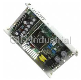
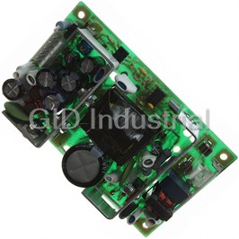
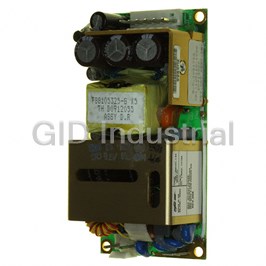
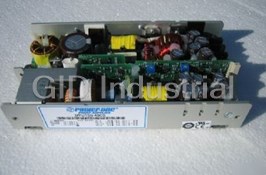
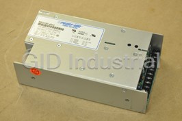
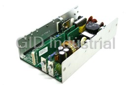
POWER-ONE BQ 2660-7R

Description
Power One BQ 2660-7R DC-DC Converter, 14.4 - 36 VDC Input Range. 24 V / 4.4 A Min. and 5.5 A Max. Output
Part Number
BQ 2660-7R
Price
Request Quote
Manufacturer
POWER-ONE
Lead Time
Request Quote
Category
POWER SUPPLY
Datasheet

Extracted Text
Q Series Data Sheet 66 – 132 Watt DC-DC Converter ® Features • RoHS lead-free-solder and lead-solder-exempted products are available • Wide input voltage ranges up to 150 VDC • 1 or 2 isolated outputs from 3.3 to 48 VDC • Class I equipment • Extremely high efficiency of up to 90% • Flexible output power • Excellent surge and transient protection • Outputs open- and short-circuit proof • Redundant operation, current sharing • Extremely low inrush current, hot swappable • Externally adjustable output voltage and inhibit • Electric strength test 2.1 kVDC • Very compact (<20 mm profile) • Railway standards observed • Telecoms-compatible input voltage range of 48Q models according to ETS 300132-2 (38.4 – 75 VDC) 111 4.4" 3 U Safety according to IEC/EN 60950-1, UL/CSA 60950-1 164 20 6.5" 0.8" 4 TE Description panel allow for a check of the main output voltage. Full system flexibility and n+1 redundant operating mode are These extremely compact DC-DC converters incorporate all possible due to virtually unrestricted series or parallel necessary input and output filtering, signaling, and protection connection capabilities of all outputs. In parallel connection of features, which are required in the majority of applications. several converters, automatic current sharing is provided by a The converters provide important advantages such as flexible single-wire interconnection. output power through primary current limitation, high efficiency, excellent reliability, very low ripple and RFI noise As a modular power supply or as part of a distributed power levels, full input to output isolation, negligible inrush current, supply system, the extremely low profile design significantly overtemperature protection, and input over-/undervoltage reduces the necessary power supply volume without lockout. The converter inputs are protected against surges sacrificing high reliability. A temperature sensor disables the and transients occurring on the source lines. outputs, if the case temperature exceeds the limit. The outputs are automatically re-enabled, when the temperature drops The converters are particularly suitable for rugged below the limit. environment, such as railway applications. They have been designed in accordance with the European railway standards The fully enclosed, black-coated aluminum case acts as a heat EN 50155 and EN 50121-3-2. All printed circuit boards are sink and an RFI shield. The converters are designed for 19" coated with a protective lacquer. DIN-rack systems occupying 3U/4TE only, but can also be chassis-mounted by means of four screws. It is possible to fit The outputs are continuously open- and short-circuit proof. An an additional heat sink. isolated output Power Good signal and LEDs at the front panel indicate the status of the converter. Test sockets at the front Table of Contents Page Page Description .......................................................................... 1 Electromagnetic Compatibility (EMC) ............................... 19 Model Selection .................................................................. 2 Immunity to Environmental Conditions ............................. 21 Functional Description ........................................................ 5 Mechanical Data ............................................................... 22 Electrical Input Data ............................................................ 6 Safety and Installation Instructions ................................... 23 Electrical Output Data ......................................................... 8 Description of Options ...................................................... 24 Auxiliary Functions ............................................................ 16 Accessories....................................................................... 26 BCD20011-G Rev AD, 22-Dec-09 Page 1 of 26 www.power-one.com Q Series Data Sheet 66 – 132 Watt DC-DC Converter ® Model Selection Table 1a: Model types BQ, GQ 1 Output 1 Output 2 Output power Operating input voltage range, efficiency Options 2 2 V I I V I I T = 71 °C T = 50 °C V – V η η η V – V η η η η η η η o nom o nom o max o nom o nom o max A A i min i max min i min i max min [VDC] [A] [A] [VDC] [A] [A] P [W] P [W] 14.4 – 36 VDC [%] 21.6 – 54 VDC [%] o nom o max 3.3 20* 25* - - - 66* 82* BQ1101-9 81* GQ1101-9 -7, B, B1, G 5.1 16 20 - - - 82 102 BQ1001-9R 85 GQ1001-9R 85.5 -7, P, B, B1, G 3 12 8 10 - - - 96 120 BQ2320-9R 86 GQ2320-9R 86 -7, P, B, B1, G 3 15 6.6 8 - - - 99 120 BQ2540-9R 87 GQ2540-9R 86.5 -7, P, B, B1, G 3 24 4.4 5.5 - - - 106 132 BQ2660-9R 88 GQ2660-9R 88 -7, P, B, B1, G 4 4 5.1 7.5 15 5.1 7.5 15 77 97 BQ2001-9R 85 GQ2001-9R 85.5 -7, B, B1, G 4 4 12 4 9.2 12 4 9.2 96 120 BQ2320-9R 86 GQ2320-9R 86 -7, P, B, B1, G 4 4 15 3.3 7.4 15 3.3 7.4 99 120 BQ2540-9R 87 GQ2540-9R 86.5 -7, P, B, B1, G 4 4 24 2.2 5.1 24 2.2 5.1 106 132 BQ2660-9R 88 GQ2660-9R 88 -7, P, B, B1, G Table 1b: Model types CQ, 48Q 1 Output 1 Output 2 Output power Operating input voltage range, efficiency Options 2 2 V I I V I I T = 71 °C T = 50 °C V – V η η η η η V – V η η η η η o nom o nom o max o nom o nom o max A A i min i max min i min i max min [VDC] [A] [A] [VDC] [A] [A] P [W] P [W] 33.6* – 75 VDC [%] 38.4 – 75 VDC [%] o nom o max 3.3 20* 25* - - - 66* 82* CQ1101-9 82* -7, B, B1, G 5.1 16 20 - - - 82 102 CQ1001-9R 85 -7, P, B, B1, G 5.1 16 16 - - - 82 82 48Q1001-2R 83 B, B1, G 3 12.0 8 10 - - - 96 120 CQ2320-9R 87 -7, P, B, B1, G 3 12.0 8 8 - - - 96 96 48Q2320-2R 85 B, B1, G 3 15.0 6.6 8 - - - 99 120 CQ2540-9R 87 -7, P, B, B1, G 3 15.0 6.6 6.6 - - - 99 99 48Q2540-2R 85 B, B1, G 3 24.0 4.4 5.5 - - - 106 132 CQ2660-9R 88 -7, P, B, B1, G 3 24.0 4.4 4.4 - - - 106 106 48Q2660-2R 87 B, B1, G 4 4 5.1 7.5 15 5.1 7.5 15 77 97 CQ2001-9R 85 -7, B, B1, G 4 4 12.0 4 9.2 12.0 4 9.2 96 120 CQ2320-9R 87 -7, P, B, B1, G 4 4 12.0 4 7.2 12.0 4 7.2 96 96 48Q2320-2R 85 B, B1, G 4 4 15.0 3.3 7.4 15.0 3.3 7.4 99 120 CQ2540-9R 87 -7, P, B, B1, G 4 4 15.0 3.3 6 15.0 3.3 6 99 99 48Q2540-2R 85 B, B1, G 4 4 24.0 2.2 5.1 24.0 2.2 5.1 106 132 CQ2660-9R 88 -7, P, B, B1, G 4 4 24.0 2.2 4 24.0 2.2 4 106 106 48Q2660-2R 87 B1, G Table 1c: Model types DQ, EQ 1 Output 1 Output 2 Output power Operating input voltage range, efficiency Options 2 2 V I I V I I T = 50 °C T = 71 °C V – V η η η η η V – V η η η η η o nom o nom o max o nom o nom o max A A i min i max min i min i max min 5 [VDC] [A] [A] [VDC] [A] [A] P [W] P [W] 43 – 108 VDC [%] 65 – 150 VDC [%] o nom o max 3.3 20* 25* - - - 66* 82* DQ1101-9 82* EQ1101-9 -7, B, B1, G 5.1 16 20 - - - 82 102 DQ1001-9R 85.5 EQ1001-9R 84.5 -7, P, B1, G 3 12.0 8 10 - - - 96 120 DQ2320-9R 88 EQ2320-9R 87 -7, P, B1, G 3 15.0 6.6 8 - - - 99 120 DQ2540-9R 88 EQ2540-9R 87.5 -7, P, B1, G 3 24.0 4.4 5.5 - - - 106 132 DQ2660-9R 88 EQ2660-9R 87 -7, P, B1, G 4 4 5.1 7.5 15 5.1 7.5 15 77 97 DQ2001-9R 85 EQ2001-9R 84 -7, B, B1, G 4 4 12.0 4 9.2 12.0 4 9.2 96 120 DQ2320-9R 88 EQ2320-9R 87 -7, P, B, B1, G 4 4 15.0 3.3 7.4 15.0 3.3 7.4 99 120 DQ2540-9R 88 EQ2540-9R 87.5 -7, P, B, B1, G 4 4 24.0 2.2 5.1 24.0 2.2 5.1 106 132 DQ2660-9R 88 EQ2660-9R 87 -7, P, B, B1, G * Converters with version V104 or higher. 1 The cumulated power of both outputs can not exceed the total power for the specified ambient temperature. See also Output Power at Reduced Temperature. 2 Minimum efficiency at V , I and T = 25 °C; typ. values are 2% better. i nom o nom A 3 Double-output models with both outputs connected in parallel 4 Double-output models. Output 2 is a tracking output isolated from the output 1. 5 168 V for ≤ 2 s. BCD20011-G Rev AD, 22-Dec-09 Page 2 of 26 www.power-one.com Q Series Data Sheet 66 – 132 Watt DC-DC Converter ® Part Number Description C Q 2 5 40 -9 P Input voltage range V : i 14.4 – 36 V ....................................................... B 21.6 – 54 V ....................................................... G 33.6 – 75 V ........................................................ C 38.4 – 75 V ..................................................... 48 43 – 108 V ......................................................... D 65 – 150 V ......................................................... E Series ................................................................................... Q Number of outputs: Single-output models .........................................1 Double-output models ........................................2 1 Single-output models (long case) ..................... 6 1 Double-output models (long case) ....................7 Single-output models: Nominal output voltage (main output): 3.3 V ...................................................................1 5.1 V ...................................................................0 12 V ....................................................................3 15 V ....................................................................5 24 V ................................................................ 6, 7 1 Other voltages ..........................................7, 8, 9 Other specifications or additional 1 features for single-output models ...... 01 – 99 Double-output models: nd Nominal voltage of 2 output V o2 nom 5.1 V ........................................................ 01 – 09 12 V ......................................................... 20 – 39 15 V ......................................................... 40 – 59 24 V ......................................................... 60 – 79 Other voltages or additional 1 features ................................................................... 01 – 99 Operational ambient temperature range T : A –10 to 50 °C ..................................................... -2 –25 to 71 °C ..................................................... -7 –40 to 71 °C ..................................................... -9 other ....................................................... -0, -5, -6 2 Output voltage control input (auxiliary function) ................ R 2 Potentiometer (option) ....................................................... P Additional heatsinks ....................................................... B, B1 3 RoHS compliant for all six substances .............................. G 1 Customer-specific models 2 Option P excludes feature R and vice versa 3 G is always placed at the end of the part number. Consult Power-One for availability! Example: CQ2540-9P: DC-DC converter, input voltage range 33.6 – 75 V, double-output model, each output providing 15 V/ 3.3 A, equipped with potentiometer to adjust the output voltages, operating ambient temperature T = –40 to 71 °C. A Note: All models have the following auxiliary functions, which are not shown in the type designation: input and output filter, inhibit, sense lines, current sharing, Out OK signal, LED indicators, and test sockets (not 48Q models). is 38.4 V such limiting the input current Note: 48Q models are designed according to Telecom standards ETS 300132-2 and EN 41003. V i min I to 150% of I . i i nom BCD20011-G Rev AD, 22-Dec-09 Page 3 of 26 www.power-one.com Q Series Data Sheet 66 – 132 Watt DC-DC Converter ® Product Marking 01003a Double-output Type designation, applicable safety approval and recognition model marks, CE mark, warnings, pin allocation, Power-One patents, Vo2+ 6 and company logo. Vo2– 10 Identification of LEDs, test sockets, and potentiometer. 28 i Vo1+ 4 Input voltage range and input current, nominal output voltages and currents, degree of protection, batch no., serial no., and 30 Vi+ S+ 12 data code including production site, version (modification Load 32 Vi– S– 14 status), and date of production. Vo1– 8 Output Configuration Fig. 3 The Q Series design allows different output configurations to Series output configuration cover almost every individual requirement, by simply wiring the outputs in parallel, series, or symmetrical configuration as per the following figures. For further information and for parallel 01004a and series operation of several converters see Electrical Double-output Output Data. model Vo1+ V + 4 o S+ 12 01001a Load 1 Single-output 28 i S– 14 model Vi+ Vo1– 4 30 8 GND Vo+ Load 2 32 Vi– Vo2+ 6 Vo+ 6 Vo2– 10 V – 28 i S+ 12 o Load 30 14 Vi+ S– 32 Vi– Vo– 8 Fig. 4 Vo– 10 Symmetrical output configuration (with common ground) Fig. 1 Single output configuration 01005a Double-output model 01002a Vo1+ 4 Double-output S+ 12 model Load 1 Vo2+ 6 28 i S– 14 Vo1+ 4 30 Vo1– 8 Vi+ 28 i S+ 12 32 Vi– Vo2+ 6 Load Load 2 30 Vi+ S– 14 Vo2– 10 32 Vi– Vo1– 8 Vo2– 10 Fig. 5 Independent output configuration Fig. 2 Parallel output configuration BCD20011-G Rev AD, 22-Dec-09 Page 4 of 26 www.power-one.com Q Series Data Sheet 66 – 132 Watt DC-DC Converter ® The current limitation is located at the primary side, thus Functional Description limiting the total output current in overload conditions. This The converters are designed as forward converters using allows flexible loading of each output for unsymmetrical loads primary and secondary control circuits in SMD technology. The in the range 10 to 90% of the total output power. In applications switching frequency is approximately 200 kHz under nominal with large dynamic load changes, we recommend connecting operating conditions. The built-in high-efficient input filter such a load to output 1. If output 2 is not used, it should be together with a small input capacitance generate very low connected parallel to output 1. Both outputs can either be inrush currents of short duration. After transformer isolation series- or parallel-connected (see Electrical Output Data). and rectification, the output filter reduces ripple and noise to a In normal operation, the internal control circuits are powered minimum without compromising the dynamic ability. The by a third winding of the main choke (except 48Q models). output voltage is fed to the secondary control circuit via Startup is ensured from the input voltage by a linear regulator. separate sense lines. The resultant error signal is sent to the primary control circuit via a signal transformer. Note: When the output voltage is much lower then the nominal value, this linear regulator is activated, generating considerable Double-output models have the voltage regulation of output 2 power losses. relying on the close magnetic coupling of the transformer and the output inductor together with the circuits' symmetry. 03111a 2 22 Out OK+ 24 Output Out OK– Primary i 28 control control circuit 18 T Output monitor 3 16 R 1 12 S+ Vi+ 30 4 Vo+ Input Output 6 Vo+ filter filter Vi– 32 8 Vo– Fuse 10 Vo– 1 C C y y 1 14 26 S– Isolation 20 4 1 2 3 4 Leading pins Potentiometer for option P Do not connect for models xQ1101 or with option P Do not connect Fig. 6 Block diagram of a single-output converter 03112a 2 22 Out OK+ 24 Output Out OK– Primary i 28 control control circuit 18 T Output monitor V o2 3 16 R 6 Vo2+ Output filter Vi+ 30 10 Vo2– Input 1 12 S+ filter 4 Vo1+ Vi– 32 Fuse Output C filter 1 y 26 8 Vo1– 1 14 S– C Isolation y 20 4 1 2 3 4 Leading pins Potentiometer for option P Do not connect for models with option P Do not connect Fig. 7 Block diagram of a double-output converter BCD20011-G Rev AD, 22-Dec-09 Page 5 of 26 www.power-one.com Q Series Data Sheet 66 – 132 Watt DC-DC Converter ® Electrical Input Data General Conditions: – T = 25 °C, unless T is specified. A C – Sense lines connected directly at the connector, inhibit (28) connected to Vi– (32). – R input not connected; with option P, V set to V at V . o o nom i nom Table 2a: Input data Input BQ GQ CQ Unit Characteristics Conditions min typ max min typ max min typ max V Operating input voltage I = 0 – I 14.4 36 21.6 54 33.6 75 V i o o max T – T C min C max V Nominal input voltage 24 36 48 i nom V Input voltage limits without damage 0 50 0 63 0 100 i abs 1 I Typical input current V , I 4.5 3.0 2.2 A i i nom o nom P No-load input power V – V 2.5 3.0 2.5 W i 0 i min i max I = 0 o 4 P Idle input power 1.0 1.5 1.5 i inh 2 I Peak inrush current V , I 55 40 35 A inr p i nom o nom t Rise time inrush 50 40 35 ms inr r t Time to half value 130 110 80 inr h 3 t Start-up time 0 → V , I 558 d on i min o nom Table 2b: Input data 2 Input 48Q DQ EQ Unit Characteristics Conditions min typ max min typ max min typ max V Operating input voltage I = 0 – I 38.4 75 43 108 65 150 V i o o max T – T C min C max for ≤2 s n.a. n.a. 65 168 for ≤100 ms n.a. 36 115 55 176 V Nominal input voltage 48 72 110 i nom V Input voltage limits without damage 0 100 0 125 0 200 i abs 1 I Typical input current V , I 2.2 1.5 1.0 A i i nom o nom P No-load input power V – V 2.5 5.5 5.0 W i 0 i min i max I = 0 o 4 P Idle input power 1.5 3.5 3.5 i inh 2 I Peak inrush current V , I 35 20 45 A inr p i nom o nom t Rise time inrush 35 50 15 ms inr r t Time to half value 80 90 25 inr h 3 t Start-up time 0 →V , I 8 20* 20* d on i min o nom * Models with version V104 or higher 1 Typical input current depends on model type 2 According to ETS 300132-2 3 See fig. 19 4 Converter inhibited BCD20011-G Rev AD, 22-Dec-09 Page 6 of 26 www.power-one.com Q Series Data Sheet 66 – 132 Watt DC-DC Converter ® Input Fuse Input Stability with Long Supply Lines An incorporated fuse in series to the negative input line If a Q Series converter is connected to the power source with protects against severe defects. The fuse is not externally long input lines exhibiting a considerable inductance, an accessible. Reverse polarity at the input will cause the fuse to additional external capacitor connected in parallel to the input blow. improves stability and avoids oscillations. Actually, a Q Series converter with nominal load acts like a Table 3: Fuse specifications negative resistor, as the input current rises when the input Model Fuse type Reference and rating voltage decreases. It tends to oscillate with a resonant frequency determined by the line inductance L and the input BQ very fast acting 2× Littelfuse 251, 10 A, 125 V ext capacitance C + C and damped by the resistors R + R . i ext i ext GQ very fast acting 2× Littelfuse 251, 7 A, 125 V The whole system is not linear at all and eludes a simple CQ very fast acting Littelfuse 251, 10 A, 125 V calculation. One basic condition is given by the formula: 48Q very fast acting Littelfuse 251, 10 A, 125 V V ² in R << —— — • η ext P DQ very fast acting Littelfuse 251, 7 A, 125 V o R is the series resistor of the source voltage including input ext EQ very fast acting Littelfuse 263, 5 A, 250 V lines. If this condition is not fulfilled, the converter cannot reach stable operating conditions. Worst case conditions are low input voltage V and high output power P . Input Transient Protection i o Low inductance L of the input lines and a parallel connected A metal oxide VDR (Voltage Dependent Resistor) together with ext input capacitor C are helpful. Recommended values for C the input fuse and a symmetrical input filter form an effective ext ext are given in table 4, which should allow stable operation up to protection against high input transient voltages, which typically an input inductance of 2 mH. occur in most installations, especially in battery-driven mobile applications. Nominal battery voltages in use are: 24, 36, 48, 60, 72, 96, and 110 V. In most cases each nominal value is specified JM001 L R ext ext Vi+ Vo+ in a tolerance band of –30% to +25%, with short + excursions to ±40% or even more. C C R In some applications, surges according to RIA12 are ext i i specified in addition to those defined in IEC 60571-1 or EN 50155. The power supply must not switch off during Vi– Vo– these surges and since their energy can practically not be absorbed, an extremely wide input voltage range is Fig. 8 required. The Q Series input range has been designed Input configuration and tested to meet most of these requirements. See also Electromagnetic Immunity. Table 4: Recommended values for C ext Input Under-/Overvoltage Lockout Model Capacitance Voltage If the input voltage remains below approx. 0.9 V or exceeds i min BQ ≥680 μF 40 V , an internally generated inhibit signal approx. 1.1 V i max disables the output(s). GQ ≥470 μF 63 V CQ ≥470 μF 100 V Inrush Current 48Q ≥470 μF 100 V The inherent inrush current value is lower than specified in the DQ ≥150 μF 125 V standard ETS 300132-2. The converters operate with EQ ≥68 μF 200 V relatively small input capacitance resulting in low inrush current of short duration. As a result, in a power-bus system the converters can be hot plugged-in or disconnected causing negligible disturbance. BCD20011-G Rev AD, 22-Dec-09 Page 7 of 26 www.power-one.com Load Q Series Data Sheet 66 – 132 Watt DC-DC Converter ® Electrical Output Data General Conditions: – T = 25 °C, unless T is specified. A C – Sense lines connected directly at the connector, inhibit (28) connected to Vi– (32). – R input not connected; with option P, V set to V at V . o o nom i nom Table 5a: Output data for single-output models and double-output models with both outputs in parallel configuration Output BQ – GQ1101 48Q / BQ – GQ1001 48Q / BQ – GQ2320 Unit 3.3 V 5.1 V 12 V Characteristics Conditions min typ max min typ max min typ max st V Setting voltage of 1 output V , I 3.28 3.32 5.07 5.13 11.94 12.06 V o1 i nom o nom V Worstcase output voltage V – V 3.24 3.35 5.02 5.18 11.82 12.18 ow i min i max T – T C min C max V Overvoltage limitation 4.5 4.9 5.9 6.4 13.5 15.0 o P I = 0 – I nd o o max by 2 control loop 2 3 3 I Output current V – V 0.05 25* 0 16/20 0 8.0/10 A o i min i max T – T C min C max I Nominal output current 20* 16 8.0 o nom 2 3 3 3 3 I Output current limit 26* 32.5* 16.8/21 20.8/26 8.4/10.5 10.4/12.5 oL 4 v Output Switch. frequ. V , I 15 25 10 20 10 20 mV o i nom o nom pp voltage noise BW = 20 MHz Total incl.spikes 25 50 20 50 20 40 1 3 3 P Output power V – V 82 82/102 96/120 W o max i min i max T – T C min C max 4 v Dynamic Voltage deviation V ±300 ±250 ±200 mV o d i nom 1 load I ↔ /2 I o nom o nom 4 5 t regulation Recovery time 800 800 1500 μs d V Dynamic line regulation 0 ↔ V 0.5 0.5 0.8 V o os i max (output overshoot) 0 – I o max 1 V Output via R-input 1.1•V – V n.a. 4.0 5.6 7.2 13.2 o tr i min i max voltage 0.1•I – I o nom o nom 1 trim range using opt. P T – T n.a 4.6 5.6 10.8 13.2 C min C max * Converters with version V104 or higher. 1 If the output voltage is increased above V through R-input control, option P setting, or remote sensing, the output power should be o nom reduced accordingly, so that P and T are not exceeded. o max C max 2 See Output Power at Reduced Temperature. 3 Values for 48Q / BQ – GQ 4 According to IEC/EN 61204 5 Recovery time see Dynamic load regulation. BCD20011-G Rev AD, 22-Dec-09 Page 8 of 26 www.power-one.com Q Series Data Sheet 66 – 132 Watt DC-DC Converter ® Table 5b: Output data for double-output models with both outputs in parallel configuration. General conditions as per table 5a Output 48Q /BQ – GQ2540 48Q /BQ – GQ2660 Unit 15 V 24 V Characteristics Conditions min typ max min typ max st V Setting voltage of 1 output V , I 14.93 15.08 23.88 24.12 V o1 i nom o nom V Worstcase output voltage V – V 14.78 15.23 23.64 24.36 ow i min i max T – T C min C max V Overvoltage limitation 17 19 27.5 30 o P I = 0 – I o o max of second control loop 2 3 3 I Output current V – V 0 6.6/8.0 0 4.4/5.5 A o i min i max T – T C min C max I Nominal output current 6.6 4.4 o nom 2 3 3 3 3 I Output current limit 6.9/8.4 8.6/10.4 4.6/5.75 6.2/8.0 oL 4 v Output Switch. frequ. V , I 10 20 10 25 mV o i nom o nom pp voltage noise BW = 20 MHz Total incl. spikes 20 40 20 40 1 3 3 P Output power V – V 99/120 106/132 W o max i min i max T – T C min C max 4 v Dynamic Voltage deviation V ±200 ±600 mV o d i nom 1 load I ↔ /2 I o nom o nom 4 5 t regulation Recovery time 1500 800 μs d V Dynamic line regulation 0 ↔ V 0.8 1.2 V o os i max (output overshoot) 0 – I o max 6 V Output via R-input 1.1•V – V 9.0 16.5 14.4 26.4 o tr i min i max voltage 0.1•I – I o nom o nom 1 trim range using opt. P T – T 13.5 16.5 21.6 26.4 C min C max 1 If the output voltages are increased above V through R-input control, option P setting or remote sensing, the output power should be o nom reduced accordingly so that P and T are not exceeded. o max C max 2 See Output Power at Reduced Temperature. 3 Values for 48Q /BQ – GQ 4 According to IEC/EN 61204 5 Recovery time until V remains within ±1% of V , see Dynamic load regulation. o o 6 For DQ2660 and EQ2660: 16.8 V BCD20011-G Rev AD, 22-Dec-09 Page 9 of 26 www.power-one.com Q Series Data Sheet 66 – 132 Watt DC-DC Converter ® Table 6a: Output data for double-output models with output 1 and output 2 in symmetrical or independent configuration. General conditions as per table 5a. Output 48Q /BQ – GQ2320 48Q /BQ – GQ2540 Unit 12 V /12 V 15 V /15 V Characteristics Conditions Output 1 Output 2 Output 1 Output 2 min typ max min typ max min typ max min typ max 1 V Output setting voltage V , I 11.94 12.06 11.88 12.12 14.93 15.08 14.85 15.15 V o i nom o nom V Worstcase output V – V 11.82 12.18 see Output 14.78 15.23 see Output ow i min i max voltage T – T Voltage Regulation Voltage Regulation C min C max I = 0 – I o o max V Overvoltage limitation n.a. 13.5 15 n.a. 17 19 o P of second control loop 2 3 3 3 3 I Output current V – V 0.8 7.2/9.2 0.8 7.2/9.2 0.6 6.0/7.4 0.6 6.0/7.4 A o i min i max T – T C min C max I Nominal output current 4.0 4.0 3.3 3.3 o nom 2 3 3 3 3 3 3 3 3 I Output current limit 8.4/10.5 10.4/13 8.4/10.5 10.4/13 6.9/8.4 8.6/10.4 6.9/8.4 8.6/10.4 o L 4 v Output Switch. frequ. V , I 8 16 8 16 8 16 8 16 mV o i nom o nom pp voltage BW = 20 MHz noise Total incl. spikes 16 40 16 40 16 40 16 40 1 3 3 P Output power total V – V 96/120 99/120 W o max i min i max T – T C min C max 4 v Dynamic Voltage V ±200 ±300 ±200 ±300 mV o d i nom 1 load deviation I ↔ /2 I o nom o nom 1 regulation I = /2 I o2 o nom 4 5 t Recovery 1500 1500 μs d time V Output via R-input 1.1•V - V 7.2 13.2 see Output 9.0 16.5 see Output V o tr i min i max voltage 0.1•I – I Voltage Regulation Voltage Regulation o nom o nom trim range using opt. P T – T 10.8 13.2 13.5 16.5 C min C max 1 If the output voltages are increased above V through R-input control, option P setting, or remote sensing, the output power should be o nom reduced accordingly so that P and T are not exceeded. o max C max 2 See Output Power at Reduced Temperature. 3 Values for 48Q/ BQ – GQ 4 According to IEC/EN 61204 5 Recovery time until V remains within ±1% of V , see Dynamic load regulation. o o 6 I = I + I o nom o1 o2 BCD20011-G Rev AD, 22-Dec-09 Page 10 of 26 www.power-one.com Q Series Data Sheet 66 – 132 Watt DC-DC Converter ® Table 6b: Output data for double-output models with output 1 and output 2 in symmetrical or independent configuration. General conditions as per table 5a Output 48Q2660 BQ – GQ2660 Unit 24 V /24 V 24 V /24 V Characteristics Conditions Output 1 Output 2 Output 1 Output 2 min typ max min typ max min typ max min typ max 1 V Output setting voltage V , I 23.88 24.12 23.76 24.24 23.88 24.12 23.76 24.24 V o i nom o nom V Worstcase output V – V 23.64 24.36 see Output 23.64 24.36 see Output ow i min i max voltage T – T Voltage Regulation Voltage Regulation C min C max I = 0 – I o o max V Overvoltage limitation n.a. 27.5 30 n.a. 27.5 30 o P of second control loop 2 I Output current V – V 0.4 4.0 0.4 4.0 0.4 5.1 0.4 5.1 A o i min i max T – T C min C max I Nominal output current 2.2 2.2 2.2 2.2 o nom 2 I Output current limit 4.6 6.2 4.6 6.2 5.8 8.0 5.8 8.0 o L 4 v Output Switch. frequ. V , I 10 25 10 25 10 25 10 25 mV o i nom o nom pp voltage BW = 20 MHz noise Total incl. spikes 20 40 20 40 20 40 20 40 1 P Output power total V – V 106 132 W o max i min i max T – T C min C max 4 v Dynamic Voltage V ±400 ±500 ±400 ±500 mV o d i nom 1 load deviation I ↔ /2 I o nom o nom 1 regulation I = /2 I 4 5 o2 o nom t Recovery 400 400 μs d time 3 V Output via R-input 1.1•V - V 14.4 26.4 see Output 14.4 26.4 see Output V o tr i min i max voltage 0.1•I – I Voltage Regulation Voltage Regulation o nom o nom trim range using opt. P T – T n.a. 21.6 26.4 C min C max 1 If the output voltages are increased above V through R-input control, option P setting or remote sensing, the output power should be o nom reduced accordingly so that P and T are not exceeded. o max C max 2 See: Output Power at Reduced Temperature. 3 For DQ2660 and EQ2660: 16.8 V. 4 According to IEC/EN 61204 5 Recovery time until V remains within ±1% of V , see Dynamic load regulation. o o BCD20011-G Rev AD, 22-Dec-09 Page 11 of 26 www.power-one.com Q Series Data Sheet 66 – 132 Watt DC-DC Converter ® Parallel and Series Connection + 05092a Single- or double-output models with equal output voltage can R p be connected in parallel without any precaution by inter- Out OK+ Vo2+ connecting the T-pins for equal current sharing; see fig. 9a. Out OK – Vo2– Double-output models with their outputs connected in parallel behave exactly like single-output models, and are fully i Vo1+ regulated. There is no inconvenience or restriction using R- Vi+ S+ input sense lines. Vi– S– Single-output and/or double-output models can be connected in series. For double-output models with both outputs Vo1– connected in series, consider that the effect via sense lines, R- input or option P is doubled. See fig. 9b. Parallel configuration of double-output models with both Out OK+ Vo2+ outputs connected in series is shown in fig. 9c. It is essential that the Vo1– pins of all paralleled converters are connected Vo2– Out OK – together, as the auxiliary signals are referenced to Vo1– or to Vo1+ i S–. The effect via sense lines, R-input or option P is doubled. Vi+ S+ Notes: • If the second output of double-output models is not used, Vi– S– connect it in parallel to the main output to maintain good regulation. Vo1– – + i • Parallel connection of several double-output models should always include main and second output to produce good Fig. 9b regulation. Series connection of double-output models. • Series connection of second outputs without involving their main outputs should be avoided as regulation may be poor. + 06114a • The maximum output current is limited by the output with the lowest current limit, if several outputs are connected in series. Double T R p output • Rated output voltages above 48 V (SELV = Safety Extra Low Vo2+ Voltage) need additional measures in order to comply with international safety requirements. Out OK+ Vo2– Vo1+ Out OK – + 05091a i S+ T R Vi+ S– p Vo+/Vo1+ Vi– Vo1– Out OK+ S+ R Out OK – S– i Vo–/Vo1– Double T output Vi+ Vo+/Vo2+ Vo2+ Vi– Vo–/Vo2– Out OK+ Vo2– Vo1+ Out OK – T i S+ Vo+/Vo1+ S– Vi+ S+ Out OK+ Vi– Vo1– Out OK – S– – + i R i Vo–/Vo1– Vo+/Vo2+ Vi+ Fig. 9c Parallel connection of double-output models with series- Vi– Vo–/Vo2– – + i connected outputs. Fig. 9a Parallel connection of single- and double-output models. BCD20011-G Rev AD, 22-Dec-09 Page 12 of 26 www.power-one.com Load Load Load Q Series Data Sheet 66 – 132 Watt DC-DC Converter ® produce reasonable current sharing between the parallel- Redundant Configuration connected converters. Fig. 10a shows a circuit with ORing diodes D in the positive R If one of the converters fails, the remaining converters can output lines, forming a redundant configuration. For accurate deliver the whole output power. output voltage regulation, the sense lines are connected after the ORing diodes. The T pins should be connected together to Note: The current-share logic can only increase the output voltage marginally and remains functional even in the case of a failing + 05091b converter. T D Fig. 10b shows a quite similar circuit with ORing diodes D , but R R R p Vo+/Vo1+ with different output loads. To compensate for the voltage drop of the ORing diodes (if necessary), an auxiliary circuit is added Out OK+ S+ to each power supply consisting of a small diode D and a S Out OK– S– small resistor R . We recommend a current of approximately 10 S mA through D and R . Only Load 0 benefits from a secured S S i Vo–/Vo1– supply voltage. Vo+/Vo2+ Vi+ The current sharing may be improved by interconnecting the T Vi– pins of the converters. This circuit is a bit less accurate, but Vo–/Vo2– more flexible and less sensitive. Caution: Do not connect the sense lines after the ORing diodes, T D R but directly with the respective outputs. If for some reason one of Vo+/Vo1+ the converters switches off and the ORing diode is blocking, a reverse voltage can appear between the sense pin and the Out OK+ S+ respective output pin and damage the converter. Out OK– S– Output Voltage Regulation Vo–/Vo1– i The dynamic load regulation is shown in the figure below. Vo+/Vo2+ Vi+ V o Vi– Vo–/Vo2– – + i V od V ±1% V ±1% o o Fig. 10a V Simple redundant configuration of double-output models with od t t parallel-connected outputs. d d t + 06097b I /I o o nom T 1 D R R p Vo+/Vo1+ 0.5 D S ≥ 10 µs ≥ 10 µs Out OK+ S+ 0 t R 05102c S Out OK– S– Fig. 11 i Vo–/Vo1– Deviation of V versus dynamic load change o Vi+ Vo+/Vo2+ The static load regulation measured at the sense pins is Vi– Vo–/Vo2– negligible. Correct connection of the sense lines almost eliminates any load regulation; see Sense Lines. T In a symmetrical configuration the output 1 with open R input is D R regulated to V , regardless of the output currents. If the Vo+/Vo1+ o1 nom D load on output 2 is too small (<10% of I ), its voltage will rise o nom S S+ Out OK+ and may activate the overvoltage protection, which will then R S reduce the voltage on both outputs. Out OK– S– V depends upon the load distribution: If each output is loaded o2 i Vo–/Vo1– with at least 10% of I , the deviation of V remains within o nom o2 Vo+/Vo2+ Vi+ ±5% of V . The following figures explain the regulation with o nom different load distributions up to the current limit. If I = I or o1 o2 Vi– Vo–/Vo2– – + i the two outputs are connected in series, the deviation of V o2 remains within ±1% of the value of V , provided that the o nom Fig. 10b load is at least I . o min Redundant configuration of double-output models with parallel-connected outputs. BCD20011-G Rev AD, 22-Dec-09 Page 13 of 26 www.power-one.com Load 2 Load 1 Load 0 Load Q Series Data Sheet 66 – 132 Watt DC-DC Converter ® Note: If output 2 is not used, we recommend to connect it in loop) limits the voltage V or V to approximately 1.25 • V o o2 o nom nd parallel to Vo1. This results in improved efficiency and stability. (in double-output models, the 2 output is monitored). This circuitry further protects the load in the unlikely event of a V [V] V = 14.2 V o2 o2 max 05111a malfunction of the main control circuit. I = 7.2 A o1 There is no specific built-in protection against externally I = 5.6 A o1 applied overvoltage. I = 4.0 A o1 V + 0.5 V o1 I = 2.4 A nd o1 Note: If output 2 is not loaded, the 2 control loop may I = 0.8 A o1 reduce V under boundary conditions. 01 V o1 Output Current Protection All outputs are fully protected against continuous open-circuit condition or continuous short-circuit by an electronic current V – 0.5 V o1 limitation located on the primary side. I [A] o2 Single-output models and series- or parallel-connected 0 2 46 8 10 Fig. 12 double-output models have a quasi rectangular constant Double-output models with 12 V: Voltage deviation of V o2 current limitation characteristic. versus I for different currents on output 1 o2 In double-output models, only the total current is limited, allowing free choice of load distribution between the two V [V] V = 18 V o2 o2 max 05112a outputs, up to I + I ≤ I . However, a small current should o1 o2 o max I = 6.0 A o1 remain on both outputs to guarantee good voltage regulation. I = 4.6 A o1 In case of overload (I + I > I ) both output voltages are o1 o2 o max I = 3.3 A o1 V + 0.5 V reduced simultaneously. o1 I = 2.0 A o1 I = 0.66 A o1 V /V o o nom I I I V o nom o max 05114c o L o1 1.0 0.95 V – 0.5 V o1 I [A] o2 0.5 0 2 46 8 Fig. 13 Double-output models with 15 V: Voltage deviation of V o2 versus I for different currents on output 1 o2 V [V] V = 28 V o2 o2 max 05113a 0 I o I = 4.0 A o1 I = 3.1 A o1 Fig. 15a I = 2.2 A o1 V + 1.0 V BQ – GQ models: Current limitation of a single- or a double- o1 I = 1.3 A o1 I = 0.44 A output model with series-connected outputs o1 V V /V o o nom o1 05104b 1.0 V – 1.0 V o1 I [A] o2 0.8 0 2 34 5 1 6 Fig. 14 0.6 Double-output models with 24 V: Voltage deviation of V o2 versus I for different currents on output 1 o2 0.4 Output Overvoltage Protection 0.2 Output voltage overshoot may occur, if the converter is either 0 I /I o o nom hot plugged-in or disconnected, the input voltage is switched 0 0.2 0.4 0.6 0.8 1.0 1.2 1.4 on or off, the converter is switched with an inhibit signal, or after a reset of a short circuit and power failure. Output overvoltage Fig. 15b can also result due to incorrectly wired sense lines. 48Q models: Current limitation of a single- or a double-output A fully independent output voltage monitor (second control model with series-connected outputs BCD20011-G Rev AD, 22-Dec-09 Page 14 of 26 www.power-one.com Operation at reduced I o nom temperature only I Out of specs. o L Out of specs. Q Series Data Sheet 66 – 132 Watt DC-DC Converter ® P Current distribution in overload is dependent upon the type of o overload. A short-circuit in one output will cause the full current forced 05116a P o max flow into that output, whereas a resistive overload results in cooling more even distribution and in a reduced output voltage. P o nom convection Efficiency cooling η [%] 05115a 90 V i max V T i nom C max V i min 0.45 P o nom 85 T A 80 T 50 60 70 80 90 100 °C A min Fig. 17a Output power derating versus T for BQ – GQ models A I [A] 75 o 12 3 4 5 P o Fig. 16 Efficiency versus input voltage and output current (per 05110b P o nom output). Typical values of EQ2320 at V . o nom forced convection Hold-up Time cooling cooling The Q Series converters provide virtually no hold-up time. If T C max hold-up time is required, use external output capacitors or decoupling diodes together with input capacitors of adequate 0.4 P o nom size. Formula for additional external input capacitor: 2 • P • t • 100 o h C = ––––––––––––––– T i ext A 2 2 η • (V – V ) ti i min –10 30 40 50 60 70 80 °C Fig. 17b where as: Output power derating versus T for 48Q models A C = external input capacitance [mF] i ext P = output power [W] o is not exceeded. In rack systems without proper thermal η = efficiency [%] management, the converters must not be packed too densely! In t = hold-up time [ms] h such cases the use of a 5 or 6TE front panel is recommended. V = minimum input voltage [V] i min A temperature sensor generates an internal inhibit signal, V = threshold level [V] ti which disables the outputs, if the case temperature exceeds Thermal Considerations and Protection T . The outputs are automatically re-enabled if the C max temperature drops below this limit. This feature is not fitted to If a converter is located upright in free flowing, quasi-stationary 48Q models. air (convection cooling) at the indicated maximum ambient temperature T (see table Temperature specifications), and A max is operated at its nominal input voltage and output power, the Output Power at Reduced Temperature temperature T measured at the Measuring point of case C Operating BQ – GQ models with output current beyond I o nom temperature (see Mechanical Data) will approach the indicated requires a reduction of the ambient temperature T to 50 °C or A value T after the warm-up phase. However, the C max forced cooling, in order to keep T below 85 °C. If T is C C max relationship between T and T depends heavily on the A C exceeded, the unit runs into its thermal protection and switches conditions of operation and integration into a system. The off (e.g. T > 50 °C and P > P ). See fig. 17a. A o o nom thermal conditions are influenced by input voltage, output current, airflow and temperature of surrounding components Fig. 17b shows the operation of 48Q models beyond T = 50 °C A and surfaces. T is therefore, contrary to T , an with forced cooling. A max C max indicative value only. Important: Short-term operation within the shaded area (e.g. start-up current, peak current) is possible without additional Caution: The installer must ensure that under all operating conditions T remains within the limits stated in the table measures, provided the case temperature remains below T . C C max Temperature specifications. Note: Sufficient forced cooling or an additional heat sink improves the reliability or allows T to be higher than T , as long as T A A max C max BCD20011-G Rev AD, 22-Dec-09 Page 15 of 26 www.power-one.com Q Series Data Sheet 66 – 132 Watt DC-DC Converter ® Table 7: Inhibit characteristics Auxiliary Functions Characteristics Conditions min typ max Unit Inhibit for Remote On/Off V Inhibit V = on V – V – 50 0.8 VDC inh o i min i max voltage T – T Note: If this function is not used, the inhibit pin 28 must be C min C max V = off 2.4 50 o connected with pin 32 to enable the output(s). A non- I Inhibit current V = – 50 V –500 μA inh inh connected pin 28 will be interpreted by the internal logic as an V =0 V –40 inh active inhibit signal and the output(s) will remain disabled (fail V = 50 V +500 inh safe function). An inhibit input enables (logic low, pull down) or disables (logic The output response, when enabling and disabling the output high, pull up) the output, if a logic signal, e.g. TTL, CMOS is by the inhibit input, is shown in the following figure. applied. In systems consisting of several converters, this feature may be used, for example, to control the activation sequence of the converters by means of logic signals, or to V /V 06159a o o nom t t r f allow the power source for a proper start-up, before full load is 1.01 applied. 0.99 06091a 0.1 I inh t 0 12 28 i S+ t d on I o V i V Vo+ 4 inh V i min I i Vo+ 6 0 t 30 Vi+ V o V [V] V inh i Vo– 8 2.4 32 Vi– Vo– 10 0.8 t 14 S– 26 Fig. 19 Output response as a function of V (on/off switching) or Fig. 18 i inhibit control Definition of input and output parameters Table 8: Output response times with outputs resistively loaded and R-input left open Characteristics Conditions BQ 48Q CQ GQ DQ* EQ* Unit t Output voltage rise time V , R = V /I 1.5 3 1.5 1.5 1.5 2 ms r i nom L o nom o nom (indicative values) V = 2.4 → 0.8 V i inh t Output voltage fall time V , R = V /I 3.3 V 0.5 f i nom L o nom o nom V (indicative values) V = 0.8 → 2.4 V 5 V 0.5 0.8 0.5 i min i inh 12 / 15 V 1 1 1 1.5 24 V 3 3 1.5 3 3 3 * Models with version V104 or higher Note: T function only increases the output voltage, until the Current Sharing currents are evenly shared. If in a redundant system, one The current sharing facility should be used, where several converter fails, the remaining converters keep sharing their converters are operated in parallel or redundant connection. currents evenly. This feature avoids that some converters are driven into Since the T pins are referenced to the pins S–, the S– pins of current limitation and thus produce excessive losses. As a all converters must have the same electrical potential. result, the stress of the converters is reduced, and the system Double-output converters with both outputs connected in reliability is further improved. series can also be paralleled with current sharing, if pins Vo1– Simple interconnection of the T pins causes the converters to of all converters are connected together, see fig. 8c. share the output current. The current tolerance of each If the output voltages are programmed to a voltage other than converter is approx. ±20% of the sum of its nominal output V by means of the R pin or option P, the outputs should be currents I + I . o nom o1 nom o2 nom adjusted individually within a tolerance of ±1%. In n+1 redundant systems, a failure of a single converter will Important: For applications using the hot plug-in capabilities, not lead to a system failure, if the outputs are decoupled by dynamic output voltage changes during plug-in/plug-out must be diodes; see fig. 10. considered. BCD20011-G Rev AD, 22-Dec-09 Page 16 of 26 www.power-one.com Load Q Series Data Sheet 66 – 132 Watt DC-DC Converter ® Programmable Output Voltage (R-Function) Note: R inputs of n converters with paralleled outputs may be paralleled too, but if only one external resistor is used, its value This feature is not available on models with 3.3 V output or with should be R /n or R /n, respectively. 1 2 option P. 06093b V ext Note: Models with 3.3 V output or with option P: The R-input must + – Double- R 16 be left open-circuit. output Vo1+ The converters offer a programmable output voltage. The 4 model adjust is performed either by an external control voltage V or ext S+ 12 an external resistor R or R , connected to the R-input. 1 2 Load 1 i S– 14 Trimming is limited to the values given in the table below (see also Electrical Output Data). With open R-input, the output Vi+ Vo1– 8 voltage is set to V . o nom Vi– Vo2+ 6 With double-output models, both outputs are affected by the Load 2 Vo2– 10 R-input settings. Fig. 20 If output voltages are set higher than V , the output currents Output adjust using an external control voltage V . o nom ext should be reduced accordingly, so that the maximum specified 06094b output power is not exceeded. R Single-output 16 R model a)Adjustment by means of an external control voltage 2 Vo+ 4 V between R (pin 16) and S– (pin 14), see fig. 20. ext R 1 Vo+ 6 V V o ext ––––––– ––––– V ≈ 2.5 V • V ≈ V • ext o o nom V 2.5 V o nom i S+ 12 Load Caution: To prevent damage, V should not exceed 20 V, nor be ext Vi+ S– 14 negative. Vi– Vo– 8 b) Adjustment by means of an external resistor: Vo– 10 The resistor can either be connected: Fig. 21 • between R (pin 16) and S– (pin 14) to set V < V , or o o nom Output adjust using a resistor R (to lower Vo) or R (to 1 2 • between R (pin 16) and S+ (pin 12) to set V > V . o o nom increase V ). o Table 9a: R for V < V ; approximate values (V , I , series E 96 resistors); R = not fitted 1 o o nom i nom o nom 2 V = 5.1 V V = 12 V V = 15 V V = 24 V o nom o nom o nom o nom 1 1 1 V (V) R [kΩ Ω Ω Ω Ω] V [V] R [kΩ Ω Ω Ω Ω] V [V] R [kΩ Ω Ω Ω Ω] V [V] R [kΩ Ω Ω Ω Ω] o 1 o 1 o 1 o 1 2 2 2 4.0 14.7 15 30.0 6.65 2 2 2 4.1 16.5 9 18 6.04 16 32.0 8.06 2 2 2 4.2 18.2 7 14 5.62 9.5 19 6.98 17 34.0 9.76 2 2 4.3 21.5 7.5 15 6.65 10 20 8.06 18 36.0 12.1 4.4 25.5 8 16 8.06 10.5 21 9.31 19 38.0 15.4 4.5 30.1 8.5 17 9.76 11 22 11 20 40.0 20 4.6 37.4 9 18 12.1 11.5 23 13.3 20.5 41.0 23.7 4.7 47.5 9.5 19 15.4 12 24 16.2 21 42.0 28.0 4.8 64.9 10 20 20 12.5 25 20 21.5 43.0 34.8 4.9 97.6 10.5 11 28 13 26 26.1 22 44.0 44.2 5 200 11 22 44.2 13.5 27 36.5 22.5 45.0 60.4 11.5 23 93.1 14 28 56.2 23 46.0 90.9 14.5 29 115 23.5 47.0 190 Table 9b: R for V > V ; approximate values (V , I , series E 96 resistors); R = not fitted 2 o o nom i nom o nom 1 V = 5.1 V V = 12 V V = 15 V V = 24 V o nom o nom o nom o nom 1 1 1 V [V] R [kΩ Ω Ω Ω Ω] V [V] R [kΩ Ω Ω Ω Ω] V [V] R [kΩ Ω Ω Ω Ω] V [V] R [kΩ Ω Ω Ω Ω] o 2 o 2 o 2 o 2 5.2 215 12.2 24.4 931 15.3 30.6 1020 24.5 49 1690 5.3 110 12.4 24.8 475 15.5 31 619 25 50 866 5.4 75 12.6 25.2 316 15.7 31.4 453 25.5 51 590 5.5 57.6 12.8 25.6 243 16 32 316 26 52 442 5.6 46.4 13 26.0 196 16.2 32.4 267 26.4 52.8 374 13.2 26.4 169 16.5 33 221 1 First column: single or double output models with separated/paralleled outputs, second column: outputs in series connection. 2 Not possible for DQ2660 and EQ2660. BCD20011-G Rev AD, 22-Dec-09 Page 17 of 26 www.power-one.com Q Series Data Sheet 66 – 132 Watt DC-DC Converter ® Output Good Signal (Out-OK) pick-up, wire the sense lines parallel or twisted. For unsymmetrical loads, we recommend connecting the sense The isolated Out-OK output gives a status indication of the lines directly at the female connector. converter and the output voltage. It can be used for control To ensure correct operation, both sense lines must be functions such as data protection, central system monitoring or connected to their respective power output. With double- as a part of a self-testing system. It can be connected to get a output models, the sense lines must be connected to output 1 centralized fault detection or may be used for other system- only. Caution should be exercised, if outputs are series- specific applications at the primary or the secondary side of connected, as the compensated voltage is effectively doubled. the converter. Because the effective output voltage and output power are Connecting the Out-OK as per fig. 22, V <1.0 V indicates that OK increased by the sense lines, the minimum input voltage rises the V or V of the converter is within the range V – V . o o1 t1 low t1 high proportionally to the compensated output voltage. V corresponds to 0.95 - 0.98 V , V to 1.02 – 1.05 t1 low o1 nom t1 high Caution: Sense lines should always be connected. Incorrectly V . o1 nom connected sense lines may cause an overvoltage at the ouput, Note: Using the R-input or the option P, the monitor level is which could damage the output load and activate the second tracking the programmed output voltage. control loop. The sense lines can handle only small currents. Note: Sense line connection in a redundant configuration is shown In an error condition, if the output voltage is out of range due to in fig. 10. overload or an external overvoltage, V will approach V OK p. The output is formed by an NPN transistor. The emitter (Out Table 12: Voltage compensation by sense lines OK–) can be connected to primary Vi– or secondary Vo1– to Nominal output Δ Δ Δ Δ ΔV Δ Δ Δ Δ ΔV Sum of Unit get an open-collector output. In a configuration of several Q S+ S– voltage Δ Δ Δ Δ ΔV + Δ Δ Δ Δ ΔV S+ S– Series converters, the Out OK pins can be series-connected in order to get a system level signal (as shown in fig. 9). If one of 3.3 V, 5.1 V ≤ 0.5 ≤ 0.25 ≤ 0.5 V the converters fails, the series-connected output rises to high 12 V, 15 V ≤ 1.0 ≤ 0.5 ≤ 1.0 impedance. 24 V ≤ 1.0 ≤ 1.0 ≤ 2.0 + V p 06096a R I p 1 k OK Test Jacks 22 Out OK+ Output Test jacks (for pin diameter 2 mm) are located at the front of the 20 V control V OK converter monitoring the main output voltage at the sense line circuit 24 Out OK– terminals. The test sockets are short-circuit protected by internal series resistors. Double-output models show the sense line voltage of output 1 at the test sockets. 48Q models Fig. 22 have no test jacks. Out OK function V LEDs p Dimensioning of resistor value R ≥ –––––– p 0.5 mA 48Q models exhibit a green LED In-OK to monitor the input Caution: Out-OK is protected by an internal series voltage. BQ – GQ models have an additional LED Out-OK, resistor and a Zener diode. To prevent damage, the which is activated simultaneously to the Out-OK signal. applied current I should be limited to ±10 mA. OK Table 11: Display status of LEDs Table 10: Out-OK data LED In OK LED Out OK Operating condition Characteristics Conditions min typ max Unit green green normal operation V Out-OK voltage Output okay, I < 0.5 mA 0.8 1.0 V OK OK green x incorrect sense line connection I Out-OK current Output fail, V ≤ 15 V 25 μA OK OK green off overtemperature overload output overvoltage Sense Lines output undervoltage This feature allows for compensation of voltage drops at the off green not possible main output across connector contacts and load lines. If the off off no input voltage sense lines are connected at the load rather than directly at the input voltage too low connector, the user must ensure that the differential voltages input voltage too high (measured on the connector) ΔV (between Vo+ and S+) and S+ inhibit input open/high ΔV (between Vo– and S–) do not exceed the values in the S– x = dependent on actual operating condition table below. Applying generously dimensioned cross-section load leads help avoiding troublesome voltage drops. To minimize noise BCD20011-G Rev AD, 22-Dec-09 Page 18 of 26 www.power-one.com Q Series Data Sheet 66 – 132 Watt DC-DC Converter ® high input transient voltages, which typically occur in most Electromagnetic Compatibility (EMC) installations, but especially in battery-driven mobile A metal oxide VDR together with an input fuse and a applications. The Q Series has been successfully tested to the symmetrical input filter form an effective protection against following specifications: Electromagnetic Immunity Table 13: Immunity type tests Phenomenon Standard Level Coupling Value Waveform Source Test In Perf. 1 2 mode applied imped. procedure oper. crit. Supply related RIA 12 B +i/–i 1.5 • V 0.1/1/0.1 s 0.2 Ω 1 positive yes A batt surge surge EN 50155 1.4 • V 1 Ω batt 4 Direct transients RIA 12 D –i/c, +i/–i 1800 V 5/50 μs5 Ω 5 pos. and 5 neg. yes A p EN 50155: impulses 5 G 8400 V 0.05/0.1 μs 100 Ω p 1995 Indirect coupled H –o/c, +o/–o, –o/–i 1800 V 5/50 μs p transients L 8400 V 0.05/0.1 μs p 6 Electrostatic IEC/EN 4 contact discharge 8000 V 1/50 ns 330 Ω 10 positive and yes B p discharge 61000-4-2 10 negative air discharge 15000 V p (to case) discharges 7 Electromagnetic IEC/EN x antenna 20 V/m 80% AM, 1 kHz n.a. 80 – 1000 MHz yes A field 61000-4-3 8 antenna 20 V/m 80% AM, 1 kHz n.a. 800 – 1000 MHz yes A 10 V/m 1400 – 2100 MHz 5 V/m 2100 – 2500 MHz 9 9 9 Electrical fast IEC/EN 3 direct coupl. (fig. 9) ±2000 V bursts of 5/50 ns 50 Ω 60 s positive yes A p transients/burst 61000-4-4: +i/c, –i/c,+i/–i 5 kHz over 15 ms 60 s negative 4 ±4000 V yes B p 2004 burst period: 300 transients per 9 3 capacit. (fig. 10) , o/c ±2000 V ms coupling mode yes B p 3 3 Surges IEC/EN 3 +i/c, –i/c ±2000 V 1.2/50 μs 12 Ω 5 pos. and 5 neg. yes B p 61000-4-5 surges per 3 3 2 +i/–i ±1000 V 2 Ω p coupling mode 10 FTZ 19 Pfl 1 +i/–i 150 V 0.1/0.3 ms <100 A 3 pos. 5 repetitions yes A p 11 Conducted IEC/EN 3 i, o, signal wires 10 VAC AM 80% 150 Ω 0.15 – 80 MHz yes A disturbances 61000-4-6 (140 dBμV) 1 kHz 1 i = input, o = output, c = case. 2 A = Normal operation, no deviation from specs, B = Temporary deviation from specs possible. 3 Measured with an external input capacitor specified in table 4. Exceeds EN 50121-3-2:2006 table 7.3 and EN 50121-4:2006 table 2.3. 4 Corresponds to EN 50155:2001, waveform A, and EN 50121-3-2:2000 table 7.2. 5 Corresponds to EN 50155:2001, waveform B. 6 Exceeds EN 50121-3-2:2006 table 9.3 and EN 50121-4:2006 table 1.4. 7 Corresponds to EN 50121-3-2:2006 table 9.1 and exceeds EN 50121-4:2006 table 1.1. Valid for version V104 or higher. 8 Corresponds to EN 50121-3-2:2006 table 9.2 and EN 50121-4:2006 table 1.2 (compliance with digital mobile phones). Valid for converters with version V104 or higher. 9 Corresponds to EN 50121-3-2:2006 table 7.2 and EN 50121-4:2006 table 2.2. Valid for converters with version V104 or higher. 10 Valid for 48Q and CQ only. 11 Corresponds to EN 50121-3-2:2006 table 7.1 and EN 50121-4:2006 table 3.1 (radio frequency common mode). BCD20011-G Rev AD, 22-Dec-09 Page 19 of 26 www.power-one.com JM022a JM023a Q Series Data Sheet 66 – 132 Watt DC-DC Converter ® dBμV PMM 8000 PLUS: Peak, conducted Vi+, Clp 2007-06-05, 15:15 h Electromagnetic Emissions EQ2660-7R V102, U =110 V, U =24 V I = 4 A, decoupled load i o o JM021 80 Table 14: Emissions at V and I i nom o nom EN 55011 B Model Class accord. to EN 55011 and EN 55022 60 Conducted 0.15 – 30 MHz Radiated 30 – 1000 MHz BQ B A 40 48Q/CQ B A DQ A A 20 EQ A A 0 GQ B A 0.2 0.5 1 2 5 10 20 MHz Note: Outputs lines decoupled with ferrite cores allow to comply with class B for radiated emissions. Fig. 23c All conducted emissions (fig. 23) have been tested according Conducted peak disturbances at the input: EQ2320-7R V102, to IEC/EN 55022 (similar to EN 55011, much better values V , I , outputs parallel connected, decoupled load lines i nom o nom than requested by EN 50121-3-2, table 3.1). The limits in fig. 23 apply to quasipeak values, which are always lower then Radiated emissions have been tested according to IEC/EN peak values. 55011 (similar to EN 55022), as requested in EN 50121-3-2, In addition, the values for average must keep a limit 10 dBμV table 6.1. The test is executed with horizontal and vertical below the limits in fig. 23 (not shown). polarization. The worse result is shown in fig. 24. PMM 8000 PLUS: Peak, conducted Vi+, Clp 2007-06-07, 14:46 h dBμV BQ1001-7R V104, U =24 V, U =5.1 V, I = 16 A, decoupled load i o o TÜV-Divina, ESVS 30:R&S, BBA 9106/UHALP 9107:Schwarzb., QP, 2009-04-21 JM019 dBμV/m Testdistance 10 m, BQ2660-7R V104, U =24 V, U =24 V I = 4.4 A 80 i o o 50 EN 55011 A EN 55022 B 60 40 40 30 20 20 10 , 0 0 0.2 0.5 1 2 5 10 20 MHz 30 50 100 200 500 1000 MHz Fig. 23a Fig. 24a Conducted peak disturbances at the input: BQ1001-7R V104, Radiated disturbances in 10 m distance: BQ2660-7R V104, V , I , decoupled load lines i nom o nom V , I i nom o nom TÜV-Divina, ESVS 30:R&S, BBA 9106/UHALP 9107:Schwarzb., QP, 2009-04-17 PMM 8000 PLUS: Peak, conducted Vi+, Clp 2007-06-07, 15:38 h Testdistance 10 m, EQ2660-7R V104, U =110 V, U =24 V I = 4.4 A dBμV i o o CQ2320-7R V104, U =48 V, U =12 V I = 8 A, decoupled load i o o JM020 80 EN 55011 A 40 EN 55022 B 60 30 40 20 20 10 0 0 30 50 100 200 500 1000 MHz 0.2 0.5 1 2 5 10 20 MHz Fig. 24b Fig. 23b Radiated disturbances in 10 m distance: EQ2660-7R V104, Conducted peak disturbances at the input: CQ2320-7R V104, V , I i nom o nom V , I , outputs parallel connected, decoupled load lines i nom o nom BCD20011-G Rev AD, 22-Dec-09 Page 20 of 26 www.power-one.com Q Series Data Sheet 66 – 132 Watt DC-DC Converter ® Immunity to Environmental Conditions Table 15: Mechanical and climatic stress Test method Standard Test conditions Status ±2 Cab Damp heat IEC/EN 60068-2-78 Temperature: 40 °C Converter +2/-3 steady state MIL-STD-810D section 507.2 Relative humidity: 93 % not Duration: 56 days operating Kb Salt mist, cyclic IEC/EN 60068-2-52 Concentration: 5% (30 °C) for 2 h Converter (sodium chloride Storage: 40°C, 93% rel. humidity for not NaCl solution) Duration: 3 cycles of 22 h operating Fc Vibration IEC/EN 60068-2-6 Acceleration amplitude: 0.35 mm (10 – 60 Hz) Converter 2 (sinusoidal) MIL-STD-810D section 514.3 5 g = 49 m/s (60 - 2000 Hz) operating n Frequency (1 Oct/min): 10 – 2000 Hz Test duration: 7.5 h (2.5 h in each axis) 2 Fh Random vibration IEC/EN 60068-2-64 Acceleration spectral density: 0.05 g /Hz Converter n broad band Frequency band: 8 – 500 Hz operating (digital control) and Acceleration magnitude: 4.9 g n rms guidance Test duration: 1.5 h (0.5 h in each axis) 2 Eb Bump IEC/EN 60068-2-29 Acceleration amplitude: 25 g = 245 m/s Converter n (half-sinusoidal) MIL-STD-810D section 516.3 Bump duration: 6 ms operating Number of bumps: 6000 (1000 in each direction) 2 Ea Shock IEC/EN 60068-2-27 Acceleration amplitude: 50 g = 490 m/s Converter n (half-sinusoidal) MIL-STD-810D section 516.3 Bump duration: 11 ms operating Number of bumps: 18 (3 in each direction) -- Shock EN 50155:2007 sect. 12.2.11, Acceleration amplitude: 5.1 g Converter n EN 61373 sect. 10, Bump duration: 30 ms operating 1 class B, body mounted Number of bumps: 18 (3 in each direction) 2 -- Simulated long life EN 50155:2007 sect. 12.2.11, Acceleration spectral density: 0.02 g /Hz Converter n testing at EN 61373 sect. 8 and 9, Frequency band: 5 – 150 Hz operating 1 increased random class B, body mounted Acceleration magnitude: 0.8 g n rms vibration levels Test duration: 15 h (5 h in each axis) 1 Body mounted = chassis of a railway coach Temperatures Table 16: Temperature specifications, valid for an air pressure of 800 - 1200 hPa (800 - 1200 mbar) Temperature -2 -7 (Option) -9 Unit Characteristics Conditions min typ max min typ max min typ max 1 1 T Ambient temperature Converter operating –10 50 –25 71 –40 71 °C A 1 2 1 2 T Case temperature –10 80 –25 95 –40 95 C T Storage temperature Non operational –25 100 –40 100 –55 100 S 1 See Thermal Considerations. Operation with P requires a reduction to T = 50 °C and T = 85 °C. o max A max C max 2 Overtemperature lockout at T >95 °C (PTC). C Reliability Table 17: MTBF and device hours Ratings at specified Models Ground Ground fixed Ground Naval, Device Unit 1 benign mobile sheltered hours Case Temperature 40 °C 40 °C 70 °C 50 °C 40 °C MTBF according to CQ1000 588 000 196 000 96 000 74 000 6 400 000 h MIL-HDBK-217F 908 000 243 000 160 000 98 000 192 000 MTBF according to BQ1001-9R MIL-HDBK-217F, notice 2 BQ2000 853 000 164 000 65 100 57 700 152 000 EQ2660-9R 913 000 237 000 155 000 97 000 188 000 1 Statistical values, based on an average of 4300 working hours per year and in general field use over 5 years; upgrades and customer- induced errors are excluded. BCD20011-G Rev AD, 22-Dec-09 Page 21 of 26 www.power-one.com Q Series Data Sheet 66 – 132 Watt DC-DC Converter ® pin 4 Mechanical Data 09066d The converters are designed to be European inserted into a 19" rack according to IEC Projection 60297-3. Dimensions are in mm. Front plate 104 M3; 4 deep Measuring point of case temperature T C AIRFLOW Main- Rear- face face 60 Back plate 111 Fig. 25 104 Case Q01, weight approx. 500 g 100 Aluminium, fully enclosed, black finish, and self cooling 95 1 LED "In-OK" green = ∅ 4.2 Potentiometer (option P) = ∅ 3.4 1 Test sockets Notes: = ∅ 3 LED "Out-OK" green Long case, elongated by 60 mm for 220 mm rack depth 1 is available on request. Not fitted to 48Q models An additional heat sink (option B1) is available; it reduces the case temperature T , and allows more C output power at higher ambient temperature T . A BCD20011-G Rev AD, 22-Dec-09 Page 22 of 26 www.power-one.com 20.32 (4 TE) 13.43 11.44 (164) 8.14 127 20 105 6.4 84.3 77.95 72.87 65.35 59.23 19.8 5.5 (171.0 ... 171.9) Q Series Data Sheet 66 – 132 Watt DC-DC Converter ® The Vi– input (pin 32) is internally fused. This fuse is designed Safety and Installation Instructions to protect in case of overcurrent and may not be able to satisfy all customer requirements. External fuses in the wiring to one Connector Pin Allocation or both input pins (no. 30 and/or no. 32) may therefore be The connector pin allocation table defines the electrical necessary to ensure compliance with local requirements. potentials and the physical pin positions on the H15 connector. Important: Pin no. 26, the protective earth pin, is a leading pin, ensuring • If the inhibit function is not used, pin 28 (i) must be connected that it makes contact with the female connector first. with pin 32 (Vi–) to enable the output(s). Table 18: Pin allocation of the H15 connector • Do not open the converters, or warranty will be invalidated. Pin Electrical determination Q1000 Q2000 • Long input, output and auxiliary lines, or lines with inductors, filters or coupling/decoupling networks may cause instabilities. 4 Output voltage (positive) Vo+ Vo1+ See Input Stability with Long Supply Lines. 6 Output voltage (positive) Vo+ Vo2+ Due to high output currents, the Q1001/1101 models offer two 8 Output voltage (negative) Vo– Vo1– internally parallel connected contacts for both the positive and the negative output path (pins 4/6 and pins 8/10). It is 10 Output voltage (negative) Vo– Vo2– recommended to connect the load to both female connector 2 12 Sense line (positive) S+ S+ pins of each path in order to keep the voltage drop across the 2 14 Sense line (negative) S– S– connector pins to a minimum. 1 1 1 16 Output voltage control input R R Make sure that there is sufficient air flow available for convection cooling. This should be verified by measuring the 18 Current sharing control input T T case temperature when the converter is installed and operated 20 Do not connect (internal Gnd.) - - in the end user application. The maximum specified case 22 Output good signal (positive) Out-OK+ Out-OK + shall not be exceeded. See also Thermal temperature T C max Considerations. 24 Output good signal (negative) Out-OK– Out-OK – 2 26 Protective earth PE Ensure that a converter failure (e.g. by an internal short-circuit) does not result in a hazardous condition. See also Safety of 3 28 Inhibit control input ii Operator-Accessible Output Circuits. 30 Input voltage (positive) Vi+ Vi+ 32 Input voltage (negative) Vi– Vi– Cleaning Agents 1 In order to avoid possible damage, any penetration of cleaning Do not connect pin 16 for models with option P or with 3.3 V output. 2 fluids must be prevented, since the power supplies are not Leading pin (pre-connecting). 3 If not actively used, connect with pin 32. hermetically sealed. 30 26 22 18 14 10 6 Protection Degree Condition: Female connector fitted to the converters. IP 30: All models, except those with option P (potentiometer). IP 20: All models fitted with option P. 10025a 32 28 24 20 16 12 8 4 Fig. 26 Standards and Approvals View of male H15 connector The Q Series converters correspond to class I equipment. They are safety agency approved to UL/CSA 60950-1, IEC Installation Instructions 60950-1, EN 60950-1. The Q Series converters are components, intended The converters have been evaluated for: exclusively for inclusion within other equipment by an industrial assembly operation or by professional installers. • Class I equipment Installation must strictly follow the national safety regulations • Building in in compliance to enclosure, mounting, creepage, clearance, • Basic insulation between input and case and double or casualty, markings and segregation requirements of the end- reinforced insulation between input and output, based on use application. their maximum rated input voltage Connection to the system shall be made via the female • Basic insulation between Out-OK and case, and double or connector H15 (see Accessories). Other installation methods reinforced insulation between Out-OK and input, and may not meet the safety requirements. between Out-OK and output, based on their maximum rated The Q Series converters are provided with pin 26 ( ), which is input voltage reliably connected to the case. For safety reasons it is • Functional insulation between outputs and output to case essential to connect this pin to protective earth; see Safety of • Use in a pollution degree 2 environment Operator-Accessible Output Circuits. BCD20011-G Rev AD, 22-Dec-09 Page 23 of 26 www.power-one.com Q Series Data Sheet 66 – 132 Watt DC-DC Converter ® Table 19: Isolation Characteristic Input to Output(s) to Output Out-OK to Out-OK Unit case + output(s) case to output case + input to output(s) 1 1 1 Electric Factory test ≥1 s 2.1 2.1 0.5* 2.1 2.1 kVDC strength 1 1 1 AC test voltage equivalent 1.5 1.5 0.35* 1.5 1.5 kVAC tests to factory test 2 2 2 2 Insulation resistance >300 >300 >100 >300 >300 MΩ 3 Minimum creepage distances 1.4 1.4 mm * Models with version V104 or higher. Older converters have only been tested with 0.3 kVDC. 1 In accordance with EN 50116 and IEC/EN 60950, subassemblies connecting input to output are pre-tested with 4.2 kVDC. 2 Tested at 500 VDC. 3 2.8 mm between input and output. converter to be SELV up to a configured output voltage (sum of • Connecting the input to a circuit, which is subject to a nominal voltages, if in series configuration) of 35 V. maximum transient rating of 1500 V. CB Scheme is available. However, it is the sole responsibility of the installer to ensure the compliance with the relevant and applicable safety The converters are subject to manufacturing surveillance in regulations. accordance with the above mentioned standards and with ISO 9001:2000. Description of Options Railway Applications The Q Series converters have been designed by observing the Option P: Output Voltage Adjustment railway standards EN 50155, EN 50121-3-2, and EN 50121-4. Option P provides a built-in multi-turn potentiometer, which All boards are coated with a protective lacquer. allows an output voltage adjustment of ±10% of V . The o nom The converters comply with class S1 of the fire protection potentiometer is accessible through a hole in the front cover. standard E DIN 5510-2 (Oct. 2007). With double-output models, both outputs are affected by the potentiometer. If different converters are parallel-connected, Isolation and Protective Earth their individual output voltage should be set within a tolerance The test of the resistance of the protective earthing circuit of ±1%. (max. 0.1 Ω) and the electric strength test (table 19) are If V is set higher than V , the output currents should be o o nom performed in the factory as routine tests in accordance with EN reduced accordingly, so that the maximum specified output 50116 and IEC/EN 60950-1, and should not be repeated in the power is not exceeded. field. Power-One will not honor any warranty claims resulting from electric strength field tests. Option -7: Temperature Range Option -7 designates converters with an operational ambient Safety of Operator-Accessible Output Circuits temperature range of –25 to 71 °C. Not for new designs. If the output circuit of a DC-DC converter is operator- accessible, it shall be an SELV circuit according to IEC 60950. Option B, B1: Additional Heat Sink Table 21 shows some possible installation configurations, Size: 12.5 mm (opt. B) or 20 mm (opt. B1) high compliance with which causes the output circuit of the DC-DC Table 20: Thermal resistance case to ambient (approx. values) 10026 Fuse ~ + Case Thermal resistance Thickness of case AC-DC Suppressor DC-DC + Mains front Battery diode con- SELV Standard (160 mm long) 1.6 K/W < 20 mm Fuse end verter 1 ~ – Case 220 mm long 1.4 K/W < 20 mm Option B 1.45 K/W < 33 mm Earth Earth Earth Option B1 1.4 K/W < 40 mm connection connection connection 1 Customer-specific models. These are as well available with an additional heat sink. Fig. 27 Schematic safety concept Use fuse, suppressor diode and earth connections as per Option G: table: Safety concept leading to an SELV output circuit. Use RoHS compliant for all six substances. fuse(s), if required by the application. See Installation Instructions. BCD20011-G Rev AD, 22-Dec-09 Page 24 of 26 www.power-one.com Q Series Data Sheet 66 – 132 Watt DC-DC Converter ® Table 21: Safety concept leading to an SELV output circuit Conditions Front end DC-DC converter Result Nominal Minimum required grade Maximum DC Minimum required Types Measures required to achieve Safety status supply of insolation, to be pro- output voltage safety status of the the specified safety status of of the DC-DC voltage vided by the AC-DC front from the front front end output the output circuit converter 1 end, including mains- end circuit output circuit supplied battery charger 2 Mains Functional (i.e. there is ≤150 V Primary circuit DQ Double or reinforced insula- SELV circuit ≤150 VAC no need for electrical iso- EQ tion, based on 150 VAC and lation between the mains DC (provided by the con- 3 supply circuit and the verter) and earthed case DC-DC converter input circuit) Basic ≤60 V ELV circuit BQ, GQ Supplementary insulation, 48Q based on 150 VAC (provided CQ by the DC-DC converter) 3 and earthed case ≤75 V Hazardous voltage 48Q Supplementary insulation, secondary circuit CQ based on 150 VAC and double or reinforced insula- 4 tion (both provided by the DC-DC converter) and 3 earthed case Mains ≤60 V Earthed SELV BQ, GQ Functional insulation (provi- 3 ≤250 VAC circuit 48Q, CQ ded by the converter) 5 ELV circuit Input fuse , output suppressor Earthed 6 diodes , earthed output SELV circuit ≤75 V Unearthed 48Q 3 3 circuit and earthed or non hazardous voltage CQ user-accessible case secondary circuit 2 ≤150 V Earthed hazardous BQ, GQ Double or reinforced SELV circuit 4 voltage secondary 48Q, CQ insulation (provided by 3 circuit or earthed DQ the converter) 3 3 ELV circuit EQ and earthed case Unearthed DQ Supplementary insulation, ba- hazardous voltage EQ sed on 250 VAC and double 4 secondary circuit or reinforced insulation (both provided by the converter) 3 and earthed case Double or reinforced ≤60 V SELV circuit BQ, 48Q Functional insulation (provi- CQ, GQ ded by the converter) 4 ≤120 V TNV-2 circuit 48Q, CQ Basic insulation (provided DQ 2 by the converter) ≤150 V Double or re-infor- EQ ced insulated un- earthed hazardous voltage secondary 7 circuit 1 The front end output voltage should match the specified input voltage range of the DC-DC converter. 2 The maximum rated input voltage of EQ models acc. to IEC/EN 60950 is 150 V. Power-One specifies the tolerance as +12% (max. 168 V) 3 The earth connection has to be provided by the installer according to IEC/EN 60950. 4 Based on the maximum rated output voltage provided by the front end. 5 The installer shall provide an approved fuse with the lowest rating suitable for the application in a non-earthed input conductor directly at the input of the DC-DC converter (see fig. Schematic safety concept). For UL’s purposes, the fuse needs to be UL-listed. 6 Each suppressor diode should be dimensioned such that in the case of an insulation fault the diode is able to limit the output voltage to SELV (<60 V), until the input fuse blows (see fig. Schematic safety concept). 7 Has to be insulated from earth according to IEC/EN 60950, by at least supplementary insulation, based on the maximum nominal output voltage from the front end. BCD20011-G Rev AD, 22-Dec-09 Page 25 of 26 www.power-one.com Q Series Data Sheet 66 – 132 Watt DC-DC Converter ® Accessories A great variety of electrical and mechanical accessories are available: • Various mating connectors including fast-on, screw, solder or press-fit terminals, code key system • Connector retention brackets CRB-Q [HZZ01217] • Cable connector housing (cable hood) KSG-H15/H15S4 [HZZ00141], also available with fixation • Various front panels wide 4, 5, or 6 TE for 19" racks with 3U heigth. Front panels with 5 or 6 TE width provide some space between the converters for better cooling. • System kit for 19" racks with 6U, width 5 TE, including a support bracket, KitG05-6HE-Q01 [HZZ01217] • Mounting plate MOUNTINGPLATE-Q [HZZ01215] for wall mounting, with optional connector retention clips RETENTIONCLIP(2X) [HZZ01209] • Brackets for DIN-rail mounting UMB-LHMQ [HZZ00610] • Additional external input and output filters • Battery sensor [S-KSMH...] for using the converter as battery charger. Different cell characteristics can be selected. For additional accessory product information, see the accessory data sheets listed with each product series or individual model listing at www.power-one.com. System kit for 19" rack, 6U. Connector retention clip Connector (only in conjunction with retention bracket mounting plate Q) CRB-Q H15 female connector, code key system Mounting plate Q for wall Brackets for DIN-rail mounting with fitted connector and chassis mounting retention clip NUCLEAR AND MEDICAL APPLICATIONS - Power-One products are not designed, intended for use in, or authorized for use as critical components in life support systems, equipment used in hazardous environments, or nuclear control systems without the express written consent of the respective divisional president of Power-One, Inc. TECHNICAL REVISIONS - The appearance of products, including safety agency certifications pictured on labels, may change depending on the date manufactured. Specifications are subject to change without notice. BCD20011-G Rev AD, 22-Dec-09 Page 26 of 26 www.power-one.com
Frequently asked questions
What makes Elite.Parts unique?

What kind of warranty will the BQ 2660-7R have?
Which carriers does Elite.Parts work with?
Will Elite.Parts sell to me even though I live outside the USA?
I have a preferred payment method. Will Elite.Parts accept it?


What they say about us
FANTASTIC RESOURCE
One of our top priorities is maintaining our business with precision, and we are constantly looking for affiliates that can help us achieve our goal. With the aid of GID Industrial, our obsolete product management has never been more efficient. They have been a great resource to our company, and have quickly become a go-to supplier on our list!
Bucher Emhart Glass
EXCELLENT SERVICE
With our strict fundamentals and high expectations, we were surprised when we came across GID Industrial and their competitive pricing. When we approached them with our issue, they were incredibly confident in being able to provide us with a seamless solution at the best price for us. GID Industrial quickly understood our needs and provided us with excellent service, as well as fully tested product to ensure what we received would be the right fit for our company.
Fuji
HARD TO FIND A BETTER PROVIDER
Our company provides services to aid in the manufacture of technological products, such as semiconductors and flat panel displays, and often searching for distributors of obsolete product we require can waste time and money. Finding GID Industrial proved to be a great asset to our company, with cost effective solutions and superior knowledge on all of their materials, it’d be hard to find a better provider of obsolete or hard to find products.
Applied Materials
CONSISTENTLY DELIVERS QUALITY SOLUTIONS
Over the years, the equipment used in our company becomes discontinued, but they’re still of great use to us and our customers. Once these products are no longer available through the manufacturer, finding a reliable, quick supplier is a necessity, and luckily for us, GID Industrial has provided the most trustworthy, quality solutions to our obsolete component needs.
Nidec Vamco
TERRIFIC RESOURCE
This company has been a terrific help to us (I work for Trican Well Service) in sourcing the Micron Ram Memory we needed for our Siemens computers. Great service! And great pricing! I know when the product is shipping and when it will arrive, all the way through the ordering process.
Trican Well Service
GO TO SOURCE
When I can't find an obsolete part, I first call GID and they'll come up with my parts every time. Great customer service and follow up as well. Scott emails me from time to time to touch base and see if we're having trouble finding something.....which is often with our 25 yr old equipment.
ConAgra Foods