

 Manufacturers
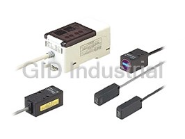
PANASONIC LS-H91F

Description
Panasonic LS-H91F Sensor - Coaxial Retroreflective, FDA Class 2 7000 275.592 Retroreflective
Part Number
LS-H91F
Price
Request Quote
Manufacturer
PANASONIC
Lead Time
Request Quote
Category
PRODUCTS - L
Specifications
Accessories
RF-330(Reflector):
Ambient Humidity
35 to 85 % RH, Storage: 35 to 85 % RH
Ambient illuminance
Incandescent light: 3,000 lx at the light-receiving face
Ambient Temperature
-10 to +55 °C +14 to +131 °F (No dew condensation or icing allowed),
Applicable amplifiers
LS-401(P), LS-401(P)-C2
Cable
0.1 mm2, single core two parallel shielded cables, 2 m 6.562 ft long
Insulation resistance
20 MO, or more, with 250 V DC megger between all supply terminals connected together and enclosure
Laser emission indicator
Green LED (lights up during laser emission)
Material
Enclosure: PBT (Mounting part: PEI), Lens cover: Acrylic
Operation indicator
Orange LED (lights up when the amplifier output is ON)
Sensing range
U-LG mode0.1 to 7 m 0.328 to 22.966 ft (Note 4)STD mode 0.1 to 5 m 0.328 to 16.404 ft (Note 4)FAST mode 0.1 to 3 m 0.328 to 9.843 ft (Note 4)
Shock Resistance
100 m/s2 acceleration (10 G approx.) in X, Y and Z directions for three times each
Spot-shape adjuster
Multi-turn adjuster
Vibration Resistance
10 to 500 Hz frequency, 1.5 mm 0.059 in (10 G max.) amplitude in X, Y and Z directions for two hours each
Voltage withstandability
1,000 V AC for one min. between all supply terminals connected together and enclosure
Weight
Net weight: 30 g approx.
Features
- 2 switches enable simple operation
- Cable type allows external input
- Easy setting, dual display
- Easy to view guide display
- Wiring and space savings
Datasheet

Extracted Text
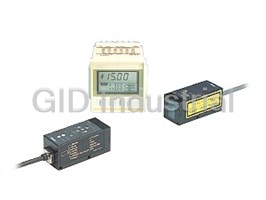
PHOTOELECTRIC SENSOR
DIGITAL LASER SENSOR
LSSERIES
FDA
Conforming to
(LS-H�F only)
UL Recognition
EMC Directive
Easy and Precise!
User-friendly, high precision laser sensing!
Announcing the new long sensing range coaxial retroreflective type with a 30 m 98.425 ft
sensing range, and the spot reflective type with Class 1 level of safety
Class 1
safety type
We offer 6 types of laser sensor heads for various applications.
Easy
Sensing
The LS-H�F (-A) FDA standard conforming
type is also available for all types.
Long sensing range line reflective type
Note: The applications given in this catalog are examples for
reference only. Stable sensing may not be possible under
certain setup conditions and environmental conditions, so
LS-H22
be sure to check the actual equipment before use.
A line width of approx. 200 mm
7.874 in (typical) at a 1,000 mm
LS-H22 LS-H22
39.370 in sensing range
Its linear sensing area enables more stable detection of objects
with complex shapes.
A line width of approx. 100 mm
3.937 in (typical) at a 500 mm
19.685 in sensing range
mA spot diameter of approx.
"1 mm "0.039 in at a 1 m
3.281 ft sensing range
Long sensing range line
reflective type LS-H22
m LS-H22 is the model No. for LS-H21
long sensing range spot reflective
type sensor head combined with the
LS-MR1 lens attachment for line
reflective type, hence LS-H21
Long sensing range
appears on the sensor head itself.
coaxial retroreflective type
LS-H92
Coaxial retroreflective type
LS-H91
Coaxial retroreflective type
Coaxial retroreflective type
LS-H91-A
Class 1 type
LS-H91-A
Sheet rolls Reflector
LS-H91
Reflector
LS-H92
Transparent films
Ultra long-range sensing up to This is a coaxial retroreflective sensor with a spot The first visible light spot for a Class 1 mThe spot diameter is a typical
example. The measurement values
30 m 98.425 ft is possible. diameter of approx. "1 mm "0.039 in (at a 1 m type (FDA standards) (as of October 2004 and
given here were determined with a
Beam axis alignment is easy 3.281 ft sensing range), so it can measure amounts based on research conducted by SUNX). This
2
center light intensity of 1/e
using the bright spot light. remaining on sheet rolls with high precision. makes beam axis alignment much easier.
(13.5%).
1
Easy 1 Installation
P3
Easy installation
We designed 3 types of sensor heads about the
same size as general purpose photoelectric sensors.
25.4 mm
1.000 in
RF-230
Easy 2 Adjustment
P4
Easy adjustment
Spot shape adjustment made simple.
30 m
(98.425 ft)
A spot diameter of approx.
m
"3 mm "0.118 in at a 3 m
9.843 ft sensing range
Compact reflector
RF-310
RF-330
Easy 3 Operation
7 m
P5
Easy operation
(22.966 ft) Uses the popular MODE NAVI feature found in fiber sensors
ensuring both multi-functionality and superior operability.
Compact reflector
RF-310
RF-330
Easy-to-use sealing-type
reflective tape available
5 m
(16.404 ft)
RF-31
RF-33
Easy 4 High Performance
P7
Complex functions made simple
Handy, on-site functionality.
mA spot diameter of approx. "1 mm
"0.039 in at a 1,000 mm
mA spot diameter of approx. 39.370 in sensing range
"1 mm "0.039 in at a 1 m
3.281 ft sensing range
1 m
(3.281 ft)
Hysteresis mode etc.
mA spot diameter of approx.
"0.3 mm "0.012 in at a 50 mm
1.969 in sensing range
Long sensing range spot reflective type
500 mm
(19.685 in)
mA spot diameter of approx.
"0.3 mm "0.012 in at a 50 mm
Long sensing range
1.969 in sensing range
LS-H21
spot reflective type
Long sensing range spot
LS-H21
Class 1 type
reflective type
Because its spot shape can be
LS-H21-A
adjusted in accordance with the object,
it can be easily set to detect even the
minutest object from a remote location.
2
Easy 1 Installation
Sensor heads are designed approximately the same size as
Easy installation
general purpose photoelectric sensors and the mounting
method is identical. (Long sensing range spot reflective / Long
sensing range line reflective / Coaxial retroreflective types)
Long sensing range line reflective type: LS-H22
Long sensing range spot reflective type: LS-H21(-A)
Coaxial retroreflective type: LS-H91(-A), LS-H92
General purpose photoelectric sensor
CX-400 series
Slim size
11.2 mm 0.441 in
Identical shape and mounting
Industry standard mounting pitch
25.4 mm
1.000 in
Industry standard mounting pitch
1
The mounting pitch for sensor heads is 25.4 mm 1.000 in, the same industry
standard as the CX-400 series general purpose photoelectric sensors. Hence,
existing mounting brackets can be used even when replacing general purpose
sensors with laser sensors.
2 Assorted mounting brackets available
Because their mounting is compatible with general purpose photoelectric sensors,
the mounting brackets for the general purpose photoelectric sensors and the
universal sensor mounting stand can be used.
MS-CX-1 MS-CX-2 MS-CX-3 MS-CX-4 MS-AJ MS-AJ� � MS-AJ MS-AJ� �-A -A
Swivel: 360 Swivel: 360� � rotation rotation
150 mm 150 mm
Elevation Elevation
5.906 in 5.906 in
angle: angle:
approx. approx.
� �45 45� �
3
Easy 2 Adjustment
Spot shape adjustment made simple.
Easy adjustment
The spot shape can be adjusted
according to the object.
Easy adjustment while
viewing the spot.
Laser emission indicator
Operation indicator
Spot-shape adjuster
Highly reliable built-in multiple turn-type knob
allows you to adjust the spot shape easily.
Spot-shape adjuster
(multiple turn)
Spot shape adjustment possible Easy and accurate adjustments
1 LS-H21, LS-H22 2 LS-H21, LS-H22
The long sensing range spot reflective type and long sensing
A spot-size adjuster is built into the back of the sensor head
range line reflective type have a built-in spot-shape adjuster
allowing the user to adjust the sensor easily while viewing
that enables spot shape adjustment according to the object
the spot. The adjuster is adjustable with a screwdriver to
for optimal setting.
avoid accidents during maintenance or any other time the
sensors are handled.
4
Easy 3 Operation
Uses MODE NAVI, highly praised in the FX-300 series digital
Easy operation fiber sensors. Besides featuring a dual display screen that shows
the incident light intensity and threshold value simultaneously, it
also offers both multi-functionality and superior operability.
10 mm 0.394 in thickness
Threshold value
setting display
Green LED, 4 digits
(Max. display: 9999)
1 Easy setting, dual display 2 Maximum display of 9999
Equipped with 2 large 4-digit digital displays. While checking The counter display’s subdivide range of up to 9999 enables
the current incident light intensity (red display), the optimal you to make extremely accurate adjustments. The result is
threshold value (green display) can be set easily. more stable sensing that ensures that even the minutest
variation in transparent objects is detected.
Easy to view guide display
3
Setting items understood at a glance.
TIMER
RUN
RUN TIMER
MODE indicators
Various timer operations
Sensing mode. The current
TEACH CUST
can be set.
incident light intensity is shown
L/D PRO
in the red digital display.
TEACH CUST
RUN TIMER
Teaching mode.
Select functions used
TEACH CUST
most often and store.
L/D PRO
Refer to p.8.
L/D PRO
RUN TIMER
This mode allows you to Set advanced function
TEACH CUST
select either Light-ON or settings.
L/D PRO
Dark-ON for output operation.
5
Current incident Large jog switch Large MODE key
light intensity display
Red LED, 4 digits
(Max. display: 9999)
4 2 switches enable simple operation
Only two switches, the large MODE key and the large jog switch, are required for operation.
1 2 3
Pressing the switch selects or Moving the switch from side Pressing the switch then
cancels the operating mode to side allows items to be confirms the selected
selected setting
5 Wiring and space savings 6 Cable type allows external input
The quick-connection cables enable reductions in wiring The LS-401-C2 cable-type amplifier is equipped with
(connector type). The connections and man-hours for the external input wires (5-core). It is ideal for using the laser
relay terminal setup can be reduced and valuable space sensors in places when external teaching or laser light
saved. Also, LS series sensors can be connected side-by- emission halting is to be carried out, or when using
side with FX-300 series fiber sensors. separately.
External input
Fiber sensor FX-300 series
• Laser emission halt
• Teaching
with 2 m 6.562 ft cable
Up to 16 units can be
connected together
Note: Because the transmission method varies depending on the
amplifiers, check the instruction manual for the amplifiers when
6
connecting them.
Easy 4 High Performance
Handy functions made simple for easy, on-site use.
Easy to use complex functions
New proposal
Accurately sense the minutest variations (M.G.S. function)
1
When sensing at close range or when the target objects are
transparent or minute, adjust the sensor receiving sensitivity
to one of 3 levels for the optimal setting. In addition, changing
the receiving sensitivity will not effect the response time. The sensitivity can be changed
without changing the response time.
Receiving sensitivity: High
Receiving sensitivity: Medium
Receiving sensitivity: Low
4 new modes enabling wide array of sensing
2
New proposal New proposal
Hysteresis mode Window comparator mode
NG: Under range
OK OK
NG: Over range
By adjusting the hysteresis, convexo-concave parts of The sensor judges any object outside the range of incident
uneven objects can be cancelled enabling more stable light intensity established by two set threshold values.
sensing.
2 independent output modes Differential sensing mode
ON
To left
OUT1
OFF
OK
ON
OUT2
To right
OFF
By combining two outputs, wide array of control is possible, Only rapid changes in light received are detected, which
allowing you to detect meandering objects, for example. enable the edge of glass, etc. to be detected accurately.
Optimal for positioning.
7
Incident light intensity
New proposal
MODE NAVI customized function
3
Because one of frequently used functions (response time,
M.G.S. function, data bank load, emission halt function and
Response time
D-CODE values) can be stored in CUSTOM mode, the
settngs are changed easily.
CUSTOM mode
M.G.S. function
Data bank load
Emission halt function
D-CODE
Equipped with handy, easy-to-use functions
4
Emission halt function External teaching function
Using the emission halt function, the laser beam can be Teaching can be conveniently performed externally for laser
stopped via external input, e.g. when a spot appears within sensors installed inside a device.
the visual range of an image processor.
New proposal
Interference prevention function Setting conditions viewed at a glance (D-CODE)
Fifth digit:
Third digit:
Hysteresis
Response time
Seventh digit:
First digit:
Custmized function
Output operation
Second digit:
Eighth digit:
Timer operation
Sensing mode
Fourth digit:
Sixth digit:
M.G.S. function
External input mode
The automatic interference prevention function protects The amplifier setting is shown as an 8-digit code. Handy for
against interference among up to 4 sensors. remote indications and follow-ups.
8
LS
ORDER GUIDE
Sensor heads
� : U-LG
Conforming �
: STD
Type Appearance Model No. Sensing range
� : FAST
standards
�
: H-SP
0.2 to 30 m 0.656 to 98.425 ft (Note 2)
JIS / IEC / GB
LS-H92
0.2 to 20 m 0.656 to 65.617 ft (Note 2)
0.2 to 10 m 0.656 to 32.808 ft (Note 2)
FDA / IEC / JIS 0.2 to 10 m 0.656 to 32.808 ft (Note 2)
LS-H92F (Note 1)
0.1 to 7 m 0.328 to 22.966 ft (Note 2)
LS-H91 JIS / IEC / GB
Coaxial 0.1 to 5 m 0.328 to 16.404 ft (Note 2)
0.1 to 3 m 0.328 to 9.843 ft (Note 2)
retroreflective
0.1 to 3 m 0.328 to 9.843 ft (Note 2)
LS-H91F (Note 1) FDA / IEC / JIS
JIS / IEC / GB
LS-H91-A 0.1 to 5 m 0.328 to 16.404 ft (Note 2)
0.1 to 3 m 0.328 to 9.843 ft (Note 2)
0.1 to 1 m 0.328 to 3.281 ft (Note 2)
LS-H91F-A (Note 1) FDA / IEC / JIS
0.1 to 1 m 0.328 to 3.281 ft (Note 2)
JIS / IEC / GB 30 to 1,000 mm 1.181 to 39.370 in
LS-H21
30 to 500 mm 1.181 to 19.685 in
30 to 300 mm 1.181 to 11.811 in
LS-H21F (Note 1) FDA / IEC / JIS 30 to 300 mm 1.181 to 11.811 in
Long sensing
range spot
reflective
30 to 500 mm 1.181 to 19.685 in
JIS / IEC / GB
LS-H21-A
30 to 250 mm 1.181 to 9.843 in
30 to 150 mm 1.181 to 5.906 in
30 to 150 mm 1.181 to 5.906 in
FDA / IEC / JIS
LS-H21F-A (Note 1)
30 to 1,000 mm 1.181 to 39.370 in
LS-H22 (Note 3) JIS / IEC / GB
Long sensing
30 to 500 mm 1.181 to 19.685 in
range line
30 to 300 mm 1.181 to 11.811 in
reflective
FDA / IEC / JIS 30 to 300 mm 1.181 to 11.811 in
LS-H22F (Note 1, 3)
NOTE: Mounting bracket is not supplied with the sensor head. Please select from the range of optional sensor head
mounting brackets.
Notes: 1) This product complies with 21 CFR 1040.10 and 1040.11 Laser Notice No. 50, dated July 26, 2001, issued by CDRH (Center for Devices and
Radiological Health) under the FDA (Food and Drug Administration). For details, refer to the Laser Notice No. 50.
2) The sensing range is the value for the RF-330 [RF-230 for the LS-H92(F)] reflector. In addition, the sensing range is the possible setting range for the
reflector. The sensor can detect an object less than 0.1 m 0.328 ft [LS-H92(F): 0.2 m 0.656 ft] away. Note that if there are white papers or specular
objects near the sensor head, reflected light from these objects may be received. In such cases, use the M.G.S. function of the amplifier unit to change
the response time or incident light sensitivity.
3) LS-H22(F) is the model No. for LS-H21(F) long sensing range spot reflective type sensor head combined with the LS-MR1 lens attachment for line
reflective type sensor head, hence LS-H21(F) appears on the sensor head itself.
5 m 16.404 ft cable length type
5 m 16.404 ft cable length types (Standard: 2 m 6.562 ft) are available. When ordering this type, add ‘-C5’ at the end of the model number.
LS-H91-C5 LS-H91-A-C5 LS-H21-C5 LS-H22-C5
Package without reflector
The LS-H91(F), LS-H91(F)-A and LS-H92(F) are also available without the reflector (RF-330 or RF-230).
When ordering this type, add ‘-Y’ at the end of the model number.
LS-H92-Y LS-H92F-Y LS-H91-Y LS-H91F-Y
LS-H91-A-Y LS-H91F-A-Y
9
Diffuse reflective
Class 2 Class 1 Class 2 Class 1 Class 2
LS
ORDER GUIDE
Amplifiers
Type Appearance Model No. Output Connection method
NPN open-collector
LS-401
transistor two outputs
Use quick-connection cable (4-core)
Connector type
(optional)
PNP open-collector
LS-401P
transistor two outputs
NPN open-collector
LS-401-C2
transistor two outputs
Cable type 2 m 6.562 ft cabtyre cable (5-core) included
(With external input) Cable outer diameter: "3.7 mm "0.146 in
PNP open-collector
LS-401P-C2
transistor two outputs
Quick-connection cables Quick-connection cable is not supplied with the connector type amplifier. Please order it separately.
Type Appearance Model No. Description
Length: 1 m 3.281 ft
CN-74-C1
2
0.15 mm 4-core cabtyre cable,
Main cable
with connector on one end
CN-74-C2 Length: 2 m 6.562 ft
(4-core)
Cable outer diameter: "3 mm "0.118 in
Length: 5 m 16.404 ft
CN-74-C5
Length: 1 m 3.281 ft
CN-72-C1
2
0.15 mm 2-core cabtyre cable,
Sub cable
Length: 2 m 6.562 ft with connector on one end
CN-72-C2
(2-core)
Cable outer diameter: "3 mm "0.118 in
Length: 5 m 16.404 ft
CN-72-C5
End plates are not supplied with the amplifier. Please order separately when the amplifiers are mounted in cascade.
End plates
Type Model No. Description
When cascading multiple amplifiers, or when it moves
depending on the way it is installed on a DIN rail, these
end plates clamp amplifiers into place on both sides. Make
MS-DIN-E
sure to use end plates when cascading multiple amplifiers
together.
Two pcs. per set
Accessories
RF-330 (Reflector) CN-EP1 (Connector for amplifier) LS-MR1 (Lens attachment for line reflective type)
5 pcs. per set (Note)
Note: One is attached to each sensor
head according to standard.
RF-230 (Reflector)
Note: LS-H92(F) only
10
LS
OPTIONS
Sensor head mounting bracket
Designation Model No. Description
• MS-CX-1 • MS-CX-2
Two M3 (length 12 mm 0.472 in) Two M3 (length 12 mm 0.472 in)
screws with washers are attached. screws with washers are attached.
MS-CX-1 Foot angled mounting bracket
Foot biangled mounting bracket
MS-CX-2 Flat mounting possible to avoid obstructions caused by the height of
Sensor head the sensor.
mounting bracket
MS-CX-3 Back angled mounting bracket
Protective mounting bracket
MS-CX-4
Protects sensors preventing beam axis displacement due to shocks.
• MS-CX-3 • MS-CX-4
Two M3 (length 12 mm 0.472 in) Two M3 (length 12 mm 0.472 in)
Horizontal mounting type
MS-AJ1
screws with washers are attached. screws with washers are attached.
Basic assembly
Universal sensor
Vertical mounting type
MS-AJ2
mounting stand
(Note) MS-AJ1-A Horizontal mounting type
Lateral arm assembly
Vertical mounting type
MS-AJ2-A
Amplifier mounting
MS-DIN-2 Mounting bracket for amplifier
bracket
Amplifier mounting bracket
Reflector mounting
Mounting bracket for RF-230
MS-RF23
bracket • MS-DIN-2
10 sets of 2 communication window seals and 1 connector seal
Communication window seal: It prevents malfunction due to transmission
Amplifier signal from another amplifier, as well as,
FX-MB1
protective seal prevents effect on another amplifier.
Connector seal: It prevents contact of any metal, etc., with the pins of
the quick-connection cable.
For coaxial retroreflective type
Reflector
RF-310
Compact reflector
Reflector mounting bracket
Sensing range (U-LG mode)
• LS-H91(F): 0.1 to 7 m
For coaxial retroreflective type
• MS-RF23
0.328 to 22.966 ft
RF-33 Size: 25.2�27.8�t 0.4 mm
• LS-H91(F)-A: 0.1 to 5 m
0.992�1.094�t 0.016 in
Reflective tape
For coaxial retroreflective type 0.328 to 16.404 ft
RF-31 Size: 9.2�9.2�t 0.4 mm
0.362�0.362�t 0.016 in
Two M4 (length 10 mm 0.394 in)
Note: Refer to the ‘sensor general catalog 2003-2004’ for details of the universal sensor mounting stand.
screws with washers are attached.
Amplifier protective seal
• FX-MB1
Communication
window seal
Connector seal
Universal sensor mounting stand
Swivel:
Swivel:
• MS-AJ1 • MS-AJ1-A
• MS-AJ2 • MS-AJ2-A 360� rotation
360�
With the lateral arm, With the lateral arm,
Swivel:
rotation
Swivel:
the sensor can sense the sensor can sense
360� rotation
360� rotation
from above a from above a
45� Height
45� Height
production production
adjustment:
adjustment:
line. line.
45�
45� 150 mm
150 mm
Elevation
5.906 in
Elevation 5.906 in
angle: 360�
360� approx.
angle:�45� approx.
�45�
Mounting hole 45�
45�
Angle 45�
45�
Mounting hole
Angle for M6 screw
adjustment:
for M6 screw
Mounting hole
adjustment:
Mounting hole
�45�
for M6 screw
�45�
for M6 screw
Reflector Reflective tape
• RF-310 • RF-33
27.8 mm
1.094 in
12 mm 0.4 mm
0.472 in 0.016 in
25.2 mm
4 mm
0.992 in
0.157 in
24 mm
0.945 in • RF-31
9.2 mm
0.362 in
0.4 mm
9.2 mm
0.016 in
0.362 in
11
LS
SPECIFICATIONS
Sensor heads
Coaxial retroreflective Diffuse reflective
Type Long sensing range spot reflective
Long sensing range
Class 2 Class 1
line reflective
Long sensing range Class 2 Class 1
IEC / JIS / GB standards conforming type LS-H92 LS-H91 LS-H91-A LS-H21 LS-H21-A LS-H22 (Note 3)
Item FDA / IEC / JIS standards conforming type (Note 2) LS-H92F LS-H91F LS-H91F-A LS-H21F LS-H21F-A LS-H22F (Note 3)
Applicable amplifiers LS-401(P), LS-401(P)-C2
0.2 to 30 m 0.1 to 7 m 0.1 to 5 m 30 to 1,000 mm 30 to 500 mm 30 to 1,000 mm
LONG mode
0.656 to 98.425 ft (Note 4) 0.328 to 22.966 ft (Note 4) 0.328 to 16.404 ft (Note 4) 1.181 to 39.370 in 1.181 to 19.685 in 1.181 to 39.370 in
0.2 to 20 m 0.1 to 5 m 0.1 to 3 m 30 to 500 mm 30 to 250 mm 30 to 500 mm
STD mode
0.656 to 65.617 ft (Note 4) 0.328 to 16.404 ft (Note 4) 0.328 to 9.843 ft (Note 4) 1.181 to 19.685 in 1.181 to 9.843 in 1.181 to 19.685 in
0.2 to 10 m 0.1 to 3 m 0.1 to 1 m
FAST mode
30 to 300 mm 30 to 150 mm 30 to 300 mm
0.656 to 32.808 ft 0.328 to 9.843 ft 0.328 to 3.281 ft
1.181 to 11.811 in 1.181 to 5.906 in 1.181 to 11.811 in
H-SP mode (Note 4) (Note 4) (Note 4)
Orange LED (lights up when the amplifier output is ON)
Operation indicator
Laser emission indicator Green LED (lights up during laser emission)
Spot-shape adjuster Multi-turn adjuster
Ambient temperature �10 to �55 �C �14 to �131 �F (No dew condensation or icing allowed), Storage: �20 to�70 �C �4 to �158 �F
35 to 85 % RH, Storage: 35 to 85 % RH
Ambient humidity
Incandescent light: 3,000 ?x at the light-receiving face
Ambient illuminance
1,000 V AC for one min. between all supply terminals connected together and enclosure
Voltage withstandability
Insulation resistance 20 MΩ, or more, with 250 V DC megger between all supply terminals connected together and enclosure
Vibration resistance 10 to 500 Hz frequency, 1.5 mm 0.059 in amplitude in X, Y and Z directions for two hours each
2
Shock resistance 100 m/s acceleration (10 G approx.) in X, Y and Z directions for three times each
Red semiconductor laser, Red semiconductor laser, Red semiconductor laser, Red semiconductor laser, Red semiconductor laser,
Class 2 (IEC / JIS / GB) Class 1 (IEC / JIS / GB) Class 2 (IEC / JIS / GB) Class 1 (IEC / JIS / GB) Class 2 (IEC / JIS / GB)
IEC / JIS / GB standards
Max. output: 3 mW Max. output: 1 mW Max. output: 3 mW Max. output: 1 mW Max. output: 3 mW
conforming type
( ( (
( (
Peak emission wavelength: 655 nm 0.026 mil Peak emission wavelength: 655 nm 0.026 mil Peak emission wavelength: 655 nm 0.026 mil Peak emission wavelength: 655 nm 0.026 mil Peak emission wavelength: 655 nm 0.026 mil
Red semiconductor laser, Red semiconductor laser, Red semiconductor laser, Red semiconductor laser, Red semiconductor laser,
Class 2 (FDA / IEC / JIS) Class 1 (FDA / IEC / JIS) Class 2 (FDA / IEC / JIS) Class 1 (FDA / IEC / JIS) Class 2 (FDA / IEC / JIS)
FDA / IEC / JIS standards
Max. output: 3 mW Max. output: 1 mW Max. output: 3 mW Max. output: 1 mW Max. output: 3 mW
conforming type (Note 2)
( ( (
( (
Peak emission wavelength: 655 nm 0.026 mil Peak emission wavelength: 655 nm 0.026 mil Peak emission wavelength: 655 nm 0.026 mil Peak emission wavelength: 655 nm 0.026 mil Peak emission wavelength: 655 nm 0.026 mil
Material Enclosure: PBT (Polybutylene terephthalate)(Mounting part: PEI), Lens cover: Acrylic
2
0.1 mm , single core two parallel shielded cables, 2 m 6.562 ft long (Connector for amplifier attached)(Note 5)
Cable
Net weight: 30 g approx. Net weight: 30 g approx. Net weight: 30 g approx. Net weight: 35 g approx.
Weight
Gross weight: 40 g approx. Gross weight: 45 g approx. Gross weight: 40 g approx. Gross weight: 45 g approx.
LS-MR1
RF-230 (Reflector): RF-330 (Reflector): RF-330 (Reflector):
Explanation label:
Lens attachment
1 pc. 1 pc. 1 pc. Warning label: 1 set
()
1 set
for line reflective : 1 pc.
Warning label: 1 set Warning label: 1 set Explanation label: 1 set Labels are written in
Warning label: 1 set
Labels are written
Labels are written in Labels are written in Labels are written Japanese, English
Accessories
Labels are written in
in Japanese and
Japanese, English Japanese, English in Japanese and and Chinese for
Japanese, English
Chinese for
and Chinese for and Chinese for Chinese for () compliance with
and Chinese for
() compliance with
() compliance with () compliance with () compliance with various standards.
() compliance with
various standards.
various standards. various standards. various standards.
various standards.
Notes: 1) Measurement conditions that are not specified are at an ambient temperature of �23 �C �73.4 �F.
2) This product complies with 21 CFR 1040.10 and 1040.11 Laser Notice No. 50, dated July 26, 2001, issued by CDRH (Center for Devices and
Radiological Health) under the FDA (Food and Drug Administration). For details, refer to the Laser Notice No. 50.
3) LS-H22(F) is the set model No. for LS-H21(F) long sensing range spot reflective type sensor head combined with the LS-MR1 lens attachment for line
reflective type, hence LS-H21(F) appears on the sensor head itself.
4) The sensing range is the value for the RF-330 [RF-230 for the LS-H92(F)] reflector. In addition, the sensing range is the possible setting range for the
reflector. The sensor can detect an object less than 0.1 m 0.328 ft [LS-H92(F): 0.2 m 0.656 ft] away. Note that if there are white papers or specular
objects near the sensor head, reflected light from these objects may be received. In such cases, use the M.G.S. function of the amplifier unit to change
the response time or incident light sensitivity.
5) Cable cannot be extended.
12
Emitting element Environmental resistance Sensing range
Model No.
( (
( ( (
( (
( ( (
LS
SPECIFICATIONS
Amplifiers
Type
Connector type Cable type
NPN output
LS-401 LS-401-C2
Item PNP output LS-401P LS-401P-C2
Supply voltage 12 to 24 V DC�10 % Ripple P-P 10 % or less
Normal operation: 950 mW or less (Current consumption 40 mA or less at 24 V supply voltage)
Power consumption
ECO mode: 780 mW or less (Current consumption 33 mA or less at 24 V supply voltage)
Frequently asked questions
What makes Elite.Parts unique?

What kind of warranty will the LS-H91F have?
Which carriers does Elite.Parts work with?
Will Elite.Parts sell to me even though I live outside the USA?
I have a preferred payment method. Will Elite.Parts accept it?
Why buy from GID?

Quality
We are industry veterans who take pride in our work

Protection
Avoid the dangers of risky trading in the gray market

Access
Our network of suppliers is ready and at your disposal

Savings
Maintain legacy systems to prevent costly downtime

Speed
Time is of the essence, and we are respectful of yours
Related Products
Request a Quote

The quote request has been received
Close

Facing challenges or have inquiries? Feel free to contact us!
Call Us +1-469-283-2440
What they say about us
FANTASTIC RESOURCE
One of our top priorities is maintaining our business with precision, and we are constantly looking for affiliates that can help us achieve our goal. With the aid of GID Industrial, our obsolete product management has never been more efficient. They have been a great resource to our company, and have quickly become a go-to supplier on our list!
Bucher Emhart Glass
EXCELLENT SERVICE
With our strict fundamentals and high expectations, we were surprised when we came across GID Industrial and their competitive pricing. When we approached them with our issue, they were incredibly confident in being able to provide us with a seamless solution at the best price for us. GID Industrial quickly understood our needs and provided us with excellent service, as well as fully tested product to ensure what we received would be the right fit for our company.
Fuji
HARD TO FIND A BETTER PROVIDER
Our company provides services to aid in the manufacture of technological products, such as semiconductors and flat panel displays, and often searching for distributors of obsolete product we require can waste time and money. Finding GID Industrial proved to be a great asset to our company, with cost effective solutions and superior knowledge on all of their materials, it’d be hard to find a better provider of obsolete or hard to find products.
Applied Materials
CONSISTENTLY DELIVERS QUALITY SOLUTIONS
Over the years, the equipment used in our company becomes discontinued, but they’re still of great use to us and our customers. Once these products are no longer available through the manufacturer, finding a reliable, quick supplier is a necessity, and luckily for us, GID Industrial has provided the most trustworthy, quality solutions to our obsolete component needs.
Nidec Vamco
TERRIFIC RESOURCE
This company has been a terrific help to us (I work for Trican Well Service) in sourcing the Micron Ram Memory we needed for our Siemens computers. Great service! And great pricing! I know when the product is shipping and when it will arrive, all the way through the ordering process.
Trican Well Service
GO TO SOURCE
When I can't find an obsolete part, I first call GID and they'll come up with my parts every time. Great customer service and follow up as well. Scott emails me from time to time to touch base and see if we're having trouble finding something.....which is often with our 25 yr old equipment.
ConAgra Foods