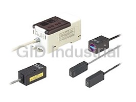
LH-50 SERIES
LED Type Optical Displacement Sensor
Minute displacements
measured with
high precision by red
�� �
LED beam
Conforming to
UL Recognition
EMC Directive
Safety precautions unnecessary Reducing total cost Compact and lightweight
The light source uses a red LED for The high-functional controller includes
Sensor head
safety. built-in calculation and measurement
Compared to our previous sensors, the
As a result, the complicated safety functions, so that the digital panel
LH-50 series sensors are much more
measures which are necessary when controller which was needed previously
compact and lightweight, so that they
using laser light are completely is no longer required, thus reducing
can easily be installed even in tight
unnecessary. costs.
spaces.
Even though a In addition, it also helps to reduce
24 mm
red LED is used, wiring and space costs.
72 mm 0.945 in
the degree of 2.835 in 17 mm
46 mm
0.669 in
1.811 in
performance
achieved is the
46 mm
Not
1.811 in
75 mm
same as for needed
2.953 in
laser-type sen-
sor class (Class Optical
shield
LH-50 series
1 to 2), so that
Previous product
high-precision
Laser-type displacement
measurement is sensor
Not needed Controller
possible.
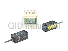
The general purpose controller is the
Digital panel controller LH-CS6(P)
most compact in its class.
Furthermore, the high-functional
Universal use
controller is a �48 mm �1.890 in
panel mounting type which can be
The LH-50 series complies with EMC
mounted on equipment panels.
directive for the CE marking.
67 mm
It uses an LED beam which is not
2.638 in
subject to FDA restrictions.
In addition, it obtains UL recognition. 40 mm
1.575 in
26 mm
1.024 in
General purpose controller
(DIN rail mounting type)
UL Recognition 77.5 mm
Conforming to
EMC Directive 3.051 in
48 mm
1.890 in
48 mm
1.890 in
High-functional controller
Panel mounting
(Panel mounting type)
904
GP-A GP-X LD LA LA-300 HL-T1 LM10 LH-50 HL-C1
MEASUREMENT SENSORS
Magnetic Displacement Light / Thru-beam Type Light / Reflective Type
LH-50
Simple and useful
• Uses an easy-to-operate jog switch • Full range of ‘ready-to-use’ and ‘useful’ functions
General purpose controller High-functional controller
Threshold value settings and other The high-functional controller is equipped with useful
Press
settings can be made easily using the calculation functions, so that the digital panel controller
Turn
extremely easy-to-operate jog switch. which was needed previously is no longer required.
Furthermore, the settings and
measurement values are indicated in
a 5-digit LED display.
5-digit LED display examples
Digital panel
controller not
(Example of measurement value) (Example of settings)
needed
LH-CD6(P) Digital panel controller
• Flexible combinations
Calculation, level difference and thickness measurements and
Sensor head General purpose controller High-functional controller
displacement from the measuring center when using a single
The LH-50 series can be used in any combination desired. sensor head are set to default settings, so that the unit can be
In addition, the sensor head and controller need not be used immediately.
managed as a pair.
Level difference measurement (A B) Thickness measurement L – (A�B)
�
Moreover, the LH-CD6(P) high-functional controller can be
connected to two sensor heads of different types.
L
Select by center measuring
AB
distance and measuring range ...
General purpose
AB
40 mm controller
Level difference
1.575 in
LH-CL6(P)
type sensor
head LH-54
High-functional
Thickness
controller (1ch)
LH-CS6(P)
80 mm
3.150 in
type sensor
High-functional
head LH-58
• Response time & resolution settings to suit the application
controller (2ch)
LH-CD6(P)
General purpose controller High-functional controller
120 mm
4.724 in Both the general purpose controller and the high-functional
type sensor
controller let you select the response time from one of eight
head LH-512
settings. (The high-functional controller also allows
automatic response time setting.)
Conventional displacement sensors generally provided
three settings, but the LH-50 series (8 settings) provides
• Automatic response time setting
much greater flexibility for response time and resolution.
High-functional controller
This device allows a highly accurate analog output suited
for any application.
The LH-CS6(P) and LH-CD6(P) high-functional controllers
are equipped with an automatic response time setting
Conventional (example) LH-50 series
function. This function sets the response time automatically in
�Response time / Resolution (2 σ)
accordance with the object’s speed of movement. It ensures
Sensor head
accurate measurement even for variable line speeds.
Model No.
In addition, it eliminates the burden of having to set the LH-54 LH-58 LH-512
Controller
response time
response time.
Priority to
2 !m 4 !m 20 !m
300 ms
resolution
0.079 mil 0.157 mil 0.787 mil
4 !m 8 !m 40 !m
100 ms
0.157 mil 0.315 mil 1.575 mil
5 !m 14 !m 65 !m
40 ms
If the line speed If the line speed
0.197 mil 0.551 mil 2.559 mil
RESPONSE
becomes faster ... OK becomes slower ... OK
6 !m
16 !m 75 !m
Fast
30 ms
0.236 mil
0.630 mil 2.953 mil
Medium
7 !m
28 !m 92 !m
Slow 20 ms
0.276 mil
1.102 mil 3.622 mil
10 !m 40 !m 130 !m
10 ms
0.394 mil 1.575 mil 5.118 mil
20 !m 120 !m 400 !m
1 ms
0.787 mil 4.724 mil 15.748 mil
Priority to 40 !m 160 !m 580 !m
0.5 ms
response 1.575 mil 6.299 mil 22.835 mil
905
Magnetic Displacement Light / Thru-beam Type Light / Reflective Type
MEASUREMENT SENSORS
GP-A GP-X LD LA LA-300 HL-T1 LM10 LH-50 HL-C1
LH-50
Simple and useful
• AUTO gain setting, SELECT gain setting General purpose controller High-functional controller
Two types of gain control are provided: AUTO and SELECT (11 settings), to provide great flexibility for a variety of applications.
Furthermore, a 7-segment display is used to indicate whether the gain is set to the optimum level.
AUTO gain setting: For objects with highly variable color and materials
AUTO gain setting This setting automatically controls the gain so that the incident
ensures accuracy light intensity is optimized to handle variations in the reflection
even for patterned ratios (variations in the amount of light received) for the
objects measured objects.
It is suitable for objects which produce large variations in
reflection ratios.
Note: Some fluctuation in resolution and linearity may occur when this
setting is used.
SELECT gain setting: For more accurate measurement using the optimum gain
This function lets you set the gain to match the reflection ratio for the measured object.
An incoming light status bar (general purpose controller) is provided to assist with setting the gain to the optimum level.
BRI. GOOD DAR. BRI. GOOD DAR. BRI. GOOD DAR. BRI. GOOD DAR. BRI. GOOD DAR.
Incident
Large light Small
intensity
m The illustrations show the display for general purpose controllers. High-functional controllers are also provided with AUTO gain and
SELECT gain settings.
• Analog output hold function General purpose controller High-functional controller
If momentary underexposure (DARK) or overexposure (BRIGHT) conditions occur, the value is held at the level immediately before
this occurs.
It allows measurement to continue without any breaks in analog output.
Measured
object
Analog output
waveform
Momentary
underexposure (DARK)
ON
Alarm output
OFF
906
GP-A GP-X LD LA LA-300 HL-T1 LM10 LH-50 HL-C1
MEASUREMENT SENSORS
Magnetic Displacement Light / Thru-beam Type Light / Reflective Type
LH-50
Simple and useful
• 16 types of setting storage memory • Two-in-one functionality
High-functional controller General purpose controller
The LH-CS6(P) and LH-CD6(P) high-functional controllers The LH-CL6(P) general purpose controller has two inde-
have 16 types of built-in setting storage memory to provide pendent comparison outputs, making it suitable for use in
greater flexibility for production lines where the model applications where two sensor units were previously required.
variety frequently changes.
Example: Measurement of products with variable heights and Example: Dimension checking after press-fitting, separation of
good / bad judgment defective items
Incomplete press-fitting OK OK Press-fitting missed
Comparative ON
Set value 1 Set value 2 Set value 3 Press-fitting missed
output 1
(FAR ON setting)
30 mm�0.5 mm 25 mm�0.3 mm 35 mm�0.8 mm OFF
1.181 in�0.020 in 0.984 in�0.012 in 1.378 in�0.031 in ON
Comparative
Incomplete press-fitting
output 2
(NEAR ON setting) OFF
APPLICATIONS
Work seating confirmation Pipe exterior distortion detection Measuring wheel eccentricity
LH-58
LH-512
LH-58
907
Magnetic Displacement Light / Thru-beam Type Light / Reflective Type
MEASUREMENT SENSORS
GP-A GP-X LD LA LA-300 HL-T1 LM10 LH-50 HL-C1
LH-50
ORDER GUIDE
Sensor heads
Spot diameter Resolution
Type Appearance Measurement center distance Model No.
(Note 1) (Note 2)
"1.6 mm "0.063 in 2 !m
LH-54
40 mm 1.575 in or less
0.079 mil
(Measuring range �10 mm �0.394 in)
"2.0 mm "0.079 in 4 !m
LH-58
80 mm 3.150 in
or less
0.157 mil
(Measuring range �20 mm �0.787 in)
"3.0 mm "0.118 in 20 !m
LH-512
120 mm 4.724 in
or less
0.787 mil
(Measuring range �30 mm �1.181 in)
2
Notes: 1) The spot diameter is a typical value for the measurement center distance given, and is based on the definition of 1/e (13.5 %) of the beam axis intensity.
2) The resolution values were obtained under the following measurement conditions.
24 V DC supply voltage, �20 ˚C �68 ˚F ambient temperature, SELECT gain setting, 300 ms response time setting, measurement center distance,
interference prevention function not used and white ceramic board object, set to 2 σ.
Controllers
Type Appearance Model No. Comparative output No. of sensor heads connected
NPN open-collector transistor
LH-CL6
(OUT1, OUT2)
1 No.
PNP open-collector transistor
LH-CL6P
(OUT1, OUT2)
NPN open-collector transistor
LH-CS6
(HI, GO, LO)
1 No.
PNP open-collector transistor
LH-CS6P
(HI, GO, LO)
NPN open-collector transistor
LH-CD6
(HI, GO, LO)
The photo shows 1 No. or 2 Nos.
PNP open-collector transistor
the LH-CD6 LH-CD6P
(HI, GO, LO)
OPTIONS
Accessory
• MS-DIN-3
Designation Model No. Description
Mounting bracket for
(
general purpose controller
Length: 2 m 6.562 ft
LH-CCJ2
Weight: 130 g approx.
2
0.22 mm cabtyre cable, with connector on both ends
Length: 5 m 16.404 ft
Extension cable
• Cable outer diameter: "6 mm "0.236 in
LH-CCJ5
Weight: 270 g approx.
• Connector outer diameter: "14.7 mm "0.579 in max.
Length: 10 m 32.808 ft
LH-CCJ10
Weight: 480 g approx.
Extension cable
• LH-CCJ2
Length
• LH-CCJ5
• LH-CCJ10
908
GP-A GP-X LD LA LA-300 HL-T1 LM10 LH-50 HL-C1
MEASUREMENT SENSORS
Magnetic Displacement Light / Thru-beam Type Light / Reflective Type
120 mm 4.724 in 80 mm 3.150 in 40 mm 1.575 in
High-functional General purpose
type type type
(
LH-50
SPECIFICATIONS Please refer to the separate ‘User’s Manual’ for more details pertaining to specifications. (Refer to p.916)
Sensor heads
Type 40 mm 1.575 in type 80 mm 3.150 in type 120 mm 4.724 in type
Item Model No. LH-54 LH-58 LH-512
Applicable controller
LH-CL6(P), LH-CS6(P), LH-CD6(P)
Measurement center distance 40 mm 1.575 in 80 mm 3.150 in 120 mm 4.724 in
�10 mm (30 to 50 mm) �20 mm (60 to 100 mm) �30 mm (90 to 150 mm)
Measuring range
�0.394 in (1.181 to 1.969 in) �0.787 in (2.362 to 3.937 in) �1.181 in (3.543 to 5.906 in)
Emitting element Red LED (modulated)(Peak wavelength: 650 nm 0.026 mil)
Spot diameter (Note 2) "1.6 mm "0.063 in or less "2.0 mm "0.079 in or less "3.0 mm "0.018 in or less
300 ms 02 !m 0.079 mil 004 !m 0.157 mil 020 !m 00.787 mil
100 ms 04 !m 0.157 mil 008 !m 0.315 mil 040 !m 01.575 mil
40 ms 05 !m 0.197 mil 014 !m 0.551 mil 065 !m 02.559 mil
30 ms
06 !m 0.236 mil 016 !m 0.630 mil 075 !m 02.953 mil
Resolution
(Note 3)
20 ms 07 !m 0.276 mil 028 !m 1.102 mil 092 !m 03.622 mil
10 ms 10 !m 0.394 mil 040 !m 1.575 mil 130 !m 05.118 mil
1 ms 20 !m 0.787 mil 120 !m 4.724 mil 400 !m 15.748 mil
0.5 ms 40 !m 1.575 mil 160 !m 6.299 mil 580 !m 22.835 mil
Linearity (Note 4) Within�0.2 % F.S.
Ambient temperature
0 to�45 °C �32 to�113 °F (No dew condensation), Storage:�20 to�60 °C �4 to�140 °F
Ambient humidity
35 to 85 % RH, Storage: 35 to 85 % RH
Protection (excluding connector part) IP67 (IEC)
2
Cable 0.22 mm 11-core composite cabtyre cable, 0.2 m 0.656 ft long, with a connector at the end
Cable extension Extension up to total 10.2 m 33.465 ft is possible, with optional cable
Weight 70 g approx. (including cable), 45 g approx. (excluding cable)
Notes: 1) Conditions which have not been specified are to be taken as: 24 V DC supply voltage,�20 °C �68 °F ambient temperature, SELECT gain setting,
300 ms response time setting, measurement center distance, interference prevention function not used and white ceramic board object.
2
Notes: 2) This is the value at the measurement center distance, and is based on the definition of 1/e (13.5 %) of the beam axis light intensity. Take care that
some amount of light spreads out of the specified spot diameter and, depending on the conditions around the measured object, may affect the
measurement accuracy.
Notes: 3) This is the typical value at the measurement center distance for a white ceramic board object. The given values are for the analog output of the
applicable controller.
Notes: 4) This is the value for white ceramic board object. The linearity may differ depending on the measured object. The given value is for the analog output of
the applicable controller.
909
Controller response time
Magnetic Displacement Light / Thru-beam Type Light / Reflective Type
MEASUREMENT SENSORS
GP-A GP-X LD LA LA-300 HL-T1 LM10 LH-50 HL-C1
LH-50
SPECIFICATIONS Please refer to the separate ‘User’s Manual’ for more details pertaining to specifications. (Refer to p.916)
Controllers
General purpose
Type
NPN output PNP output
Item Model No. LH-CL6 LH-CL6P
Applicable sensor head LH-54, LH-58, LH-512
Connectable sensor heads (Max.) 1 No.
Supply voltage 24 V DC�10 % Ripple P-P 10 % or less
Current consumption (Note 2) 250 mA or less
Analog voltage Analog current
Analog output • Output voltage:�5 to�5 V/F.S. • Output current: 4 to 20 mA/F.S.
• Output impedance: 100 Ω • Load resistance: 300 Ω or less
Response time (10 to 90 %) 0.5 ms / 1 ms / 10 ms / 20 ms / 30 ms / 40 ms / 100 ms / 300 ms selectable by jog switch
Temperature characteristics Within �0.04 % F.S./°C
Span adjustment / Shift adjustment Within �10 % F.S. (Note 2)
Independence two outputs (OUT1, OUT2) Independence two outputs (OUT1, OUT2)
NPN open-collector transistor PNP open-collector transistor
• Maximum sink current: 100 mA • Maximum source current: 100 mA
Comparative output • Applied voltage: 30 V DC or less • Applied voltage: 30 V DC or less
(between comparative output and 0 V) (between comparative output and �V)
• Residual voltage: 1.5 V or less (at 100 mA sink current) • Residual voltage: 1.5 V or less (at 100 mA source current)
0.4 V or less (at 16 mA sink current) 0.4 V or less (at 16 mA source current)
Output operation ON or OFF when threshold level is reached (selectable by jog switch)
Short-circuit protection Incorporated
Alarm output Incorporated
Ambient temperature 0 to�50 °C �32 to�122 °F (No dew condensation), Storage: �20 to�60 °C �4 to�140 °F
Ambient humidity 35 to 85 % RH, Storage: 35 to 85 % RH
2
Cable 0.22 mm 13-core composite cabtyre cable, 2 m 6.562 ft long.
Weight 160 g approx.
Accessory MS-DIN-3 (Controller mounting bracket): 1 pc.
Notes: 1) Conditions which have not been specified are to be taken as: 24 V DC supply voltage,�20 °C �68 °F ambient temperature, SELECT gain setting,
300 ms response time setting, measurement center distance, interference prevention function not used and white ceramic board object.
2) Including the sensor head.
3) The linearity of the sensor head and the controller has been adjusted at the time of factory shipment. Carry out the shift adjustment and the span
adjustment to suit the operating conditions.
High-functional
Type
NPN output PNP output
Item Model No. LH-CS6 LH-CD6 LH-CS6P LH-CD6P
Applicable sensor head LH-54, LH-58, LH-512
Connectable sensor heads (Max.) 1 No. 2 Nos. 1 No. 2 Nos.
Supply voltage 24 V DC�10 % Ripple P-P 10 % or less
Current consumption (Note 2) 300 mA or less 350 mA or less 300 mA or less 350 mA or less
Analog voltage Analog current
Analog output • Output voltage:�5 to�5 V/F.S. • Output current: 4 to 20 mA/F.S.
• Output impedance: 100 Ω • Load resistance: 300 Ω or less
Response time (10 to 90 %) 0.5 ms / 1 ms / 10 ms / 20 ms / 30 ms / 40 ms / 100 ms / 300 ms selectable by key (Automatic response time setting is possible.)
Temperature characteristics Within �0.04 % F.S./°C
Span adjustment / Shift adjustment Within �30 % F.S. (Note 3)
Three outputs (HI, GO, LO) Three outputs (HI, GO, LO)
NPN open-collector transistor PNP open-collector transistor
• Maximum sink current: 30 mA • Maximum source current: 30 mA
Comparative output • Applied voltage: 30 V DC or less • Applied voltage: 30 V DC or less
(between comparative output and 0 V) (between comparative output and �V)
• Residual voltage: 1.0 V or less (at 30 mA sink current) • Residual voltage: 1.0 V or less (at 30 mA source current)
0.4 V or less (at 16 mA sink current) 0.4 V or less (at 16 mA source current)
Output operation ON when threshold level is reached
Short-circuit protection Incorporated
Alarm output Incorporated
Strobe output Incorporated
Ambient temperature 0 to�50 °C �32 to�122 °F (No dew condensation), Storage:�20 to�60 °C �4 to�140 °F
Ambient humidity 35 to 85 % RH, Storage: 35 to 85 % RH
Weight 120 g approx.
Accessory ATA4811 (Controller mounting frame): 1 set.
Notes: 1) Conditions which have not been specified are to be taken as: 24 V DC supply voltage,�20 °C �68 °F ambient temperature, SELECT gain setting,
300 ms response time setting, measurement center distance, interference prevention function not used and white ceramic board object.
2) Including the sensor head.
3) The linearity of the sensor head and the controller has been adjusted at the time of factory shipment. Carry out the shift adjustment and the span
adjustment to suit the operating conditions.
910
GP-A GP-X LD LA LA-300 HL-T1 LM10 LH-50 HL-C1
MEASUREMENT SENSORS
Magnetic Displacement Light / Thru-beam Type Light / Reflective Type
LH-50
I/O CIRCUIT DIAGRAMS (CONTROLLER)
LH-CL6
NPN output type
Color code Notes: 1) The device connected to the analog voltage output (black) should
have an input impedance of 1 MΩ or more.
D1
(Brown)�V
Notes: 2) The device connected to the analog current output (white) should
(Black / White)
ZD1 have a load resistance of 300 Ω or less.
Comparative Load
output (OUT 1)
Notes: 3) Do not connect an interference prevention I/O wire other than that
Load
of LH-CL6(P) to the interference prevention I/O (orange / violet).
100 mA max.
Load
ZD2 Tr1
�
(Black / Gray) Comparative output (OUT 2) 24 V DC Further, do not connect together two controllers which have both
�10 %
been set as masters during interference prevention setting, as this
�
100 mA max.
ZD3 Tr2
(Gray) Alarm output will cause a fault.
100 mA max.
Tr3
(Blue) 0 V
Symbols … D1: Reverse supply polarity protection diode
D2 to D5: Input protection diode
100 Ω
�
(Black) Analog voltage output �5 to�5 V (Note 1)
� ZD1 to ZD5: Surge absorption zener diode
ZD4
Tr1 to Tr3: NPN output transistor
(Black shield) Analog voltage output GND
�12 V
m1
�
� ZD5
(White) Analog current output 4 to 20 mA (Note 2) Non-voltage contact or NPN open-collector transistor
(White shield) Analog current output GND
D2 4.7 kΩ
(Light blue) 0-ADJ input
or
D3 4.7 kΩ
(Violet) External synchronization input
• 0-ADJ input, External synchronization input • Remote interlock input
D4 4.7 kΩ Low (0 to 1 V): Effective Low (0 to 1 V): Emission
(Pink) Remote interlock input
High (�V or open): Ineffective High (�V or open): Emission halt
(Orange / Violet)
D5 4.7 kΩ
Interference
prevention I/O (Note 3)
22 kΩ
(Pink / Black) Input COM.
m1 m1 m1
22 kΩ
(Blue / White) Input COM.
Internal circuit Users’ circuit
LH-CL6P
PNP output type
Color code
Notes: 1) The device connected to the analog voltage output (black) should
have an input impedance of 1 MΩ or more.
(Brown)�V
Notes: 2) The device connected to the analog current output (white) should
have a load resistance of 300 Ω or less.
ZD1
100 mA max.
Notes: 3) Do not connect an interference prevention I/O wire other than that
Tr1
(Black / White) Comparative output (OUT 1)
of LH-CL6(P) to the interference prevention I/O (orange / violet).
ZD2 100 mA max. �
24 V DC
Further, do not connect together two controllers which have both
Tr2
�10 %
(Black / Gray) Comparative output (OUT 2) been set as masters during interference prevention setting, as this
�
Load
ZD3
100 mA max.
will cause a fault.
Tr3
Load
(Gray)
Load
D1 Alarm output
Symbols … D1: Reverse supply polarity protection diode
(Blue) 0 V
100 Ω D2 to D5: Input protection diode
�
(Black) Analog voltage output �5 to�5 V (Note 1)
�
ZD1 to ZD5: Surge absorption zener diode
ZD4
Tr1 to Tr3: PNP output transistor
(Black shield) Analog voltage output GND
�12 V
� m1
�
ZD5
(White) Analog current output 4 to 20 mA (Note 2)
Non-voltage contact or PNP open-collector transistor
(White shield) Analog current output GND
D2 4.7 kΩ
(Light blue) 0-ADJ input
or
D3 4.7 kΩ
(Violet) External synchronization input
• 0-ADJ input, External synchronization input
• Remote interlock input
D4 4.7 kΩ Low (0 to 1 V, or open): Ineffective
(Pink) Remote interlock input Low (0 to 1 V, or open): Emission halt
High (�V): Effective
High (�V): Emission
(Orange / Violet)
D5 4.7 kΩ
Interference
prevention I/O (Note 3)
22 kΩ
(Pink / Black) Input COM.
m1 m1 m1
22 kΩ
(Blue / White) Input COM.
Internal circuit Users’ circuit
911
Main circuit
Main circuit
Magnetic Displacement Light / Thru-beam Type Light / Reflective Type
MEASUREMENT SENSORS
GP-A GP-X LD LA LA-300 HL-T1 LM10 LH-50 HL-C1
LH-50
I/O CIRCUIT DIAGRAMS (CONTROLLER)
LH-CS6
NPN output type
LH-CD6
Notes: 1) The device connected to ‘1 Analog voltage output’ should have an
Terminal No.
input impedance of 1 MΩ or more.
Notes: 2) The device connected to ‘3 Analog current output’ should have a
D1
�V
11
load resistance of 300 Ω or less.
Comparative
Load
ZD1 output HI Notes: 3) In case of LH-CS6, terminal No. 6 is not used.
13
Tr1
Load
Notes: 4) Do not wire an interference prevention I/O other than that of
ZD2 30 mA max.
Comparative output GO
14 LH-CS6(P) or LH-CD6(P) to the interference prevention I/O.
Load
Tr2
�
Further, do not connect together two controllers which have both
ZD3 30 mA max.
Comparative output LO Load 24 V DC
15
Tr3
�10 % been set as masters during interference prevention setting, as this
�
Load
30 mA max.
ZD4 Strobe output
will cause a fault.
16
Tr4
30 mA max.
ZD5 Alarm output
17
Tr5 Symbols … D1: Reverse supply polarity protection diode
30 mA max.
0 V D2 to D7: Input protection diode
12
100 Ω
ZD1 to ZD7: Surge absorption zener diode
�
1
Analog voltage output �5 to�5 V (Note 1)
�
Tr1 to Tr5: NPN output transistor
ZD6
2
GND for analog output
�12 V
m1
�
ZD7
�
3 Analog current output 4 to 20 mA (Note 2)
Non-voltage contact or NPN open-collector transistor
D2 4.7 kΩ
BUSY input HEAD 1
5
D3 4.7 kΩ
BUSY input HEAD 2 (Note 3)
6
or
D4 4.7 kΩ
Calculation hold reset input
7
D5 4.7 kΩ • Remote interlock input
0-ADJ input • 0-ADJ input, BUSY input
19
Low (0 to 1 V): Emission
Calculation hold reset input
D6 4.7 kΩ
Remote interlock input
High (�V or open): Emission halt
9 Low (0 to 1 V): Effective
Interference
D7 4.7 kΩ
High (�V or open): Ineffective
prevention I/O
4
(Note 4)
Input COM.
Upper terminal block Lower terminal block
10 m1 m1 m1 m1 m1
Input COM. Terminal Terminal
Description Description
18
No. No.
Input COM.
8
1 Analog voltage output A �V
2 GND for analog output B 0 V
1234567890
Internal circuit Users’ circuit
3 Analog current output C Comparative output HI
Terminal
4 Interference prevention I/O D Comparative output GO
No.
Upper terminal
Terminal arrangement diagram
5 BUSY input HEAD 1 E Comparative output LO
block
6 BUSY input HEAD 2 (Note) F Strobe output
Lower terminal 7 Calculation hold reset input G Alarm output
block 8 Input COM. H Input COM.
9 Remote Interlock input I 0-ADJ input
0 Input COM.
ABCDEFGHI
Note: Not for the LH-CS6
LH-CS6P
PNP output type
LH-CD6P
Notes: 1) The device connected to ‘1 Analog voltage output’ should have an
Terminal No.
input impedance of 1 MΩ or more.
Notes: 2) The device connected to ‘3 Analog current output’ should have a
ZD1
�V
11
load resistance of 300 Ω or less.
30 mA max.
Comparative output HI
Notes: 3) In case of LH-CS6P, terminal No. 6 is not used.
13
Tr1
Notes: 4) Do not wire an interference prevention I/O other than that of
30 mA max.
ZD2 Comparative output GO
Tr2 LH-CS6(P) or LH-CD6(P) to the interference prevention I/O.
14
Comparative output LO 30 mA max. Load
ZD3
� Further, do not connect together two controllers which have both
24 V DC
Tr3 15
Load �10 % been set as masters during interference prevention setting, as this
30 mA max. �
ZD4 Strobe output
will cause a fault.
Tr4 16 Load
30 mA max.
Alarm output
Load
Tr5 17
Symbols … D1: Reverse supply polarity protection diode
ZD5
Load
D1
0 V
D2 to D7: Input protection diode
12
100 Ω
ZD1 to ZD7: Surge absorption zener diode
�
1 Analog voltage output �5 to�5 V (Note 1)
�
Tr1 to Tr5: PNP output transistor
ZD6
2
GND for analog output
�12 V
m1
�
ZD7
�
3 Analog current output 4 to 20 mA (Note 2)
Non-voltage contact or PNP open-collector transistor
D2 4.7 kΩ
BUSY input HEAD 1
5
D3 4.7 kΩ
BUSY input HEAD 2 (Note 3)
6
or
D4 4.7 kΩ
Calculation hold reset input
7
D5 4.7 kΩ • 0-ADJ input, BUSY input • Remote interlock input
0-ADJ input
19
Calculation hold reset input Low (0 to 1 V, or open): Emission halt
D6 4.7 kΩ
Remote interlock input
Low (0 to 1 V, or open): Ineffective High (�V): Emission
9
Interference
D7 4.7 kΩ High (�V): Effective
prevention I/O
4
(Note 4)
Input COM.
Upper terminal block Lower terminal block
10 m1 m1 m1 m1 m1
Input COM. Terminal Terminal
18 Description Description
No. No.
Input COM.
8
1 Analog voltage output A V
�
2 GND for analog output B 0 V
1234567890
Internal circuit Users’ circuit
3 Analog current output C Comparative output HI
Terminal
4 Interference prevention I/O D Comparative output GO
No.
Upper terminal
Terminal arrangement diagram 5 BUSY input HEAD 1 E Comparative output LO
block
6 BUSY input HEAD 2 (Note) F Strobe output
7 Calculation hold reset input G Alarm output
Lower terminal
block 8 Input COM. H Input COM.
9 Remote Interlock input I 0-ADJ input
0 Input COM.
ABCDEFGHI
Note: Not for the LH-CS6P
912
GP-A GP-X LD LA LA-300 HL-T1 LM10 LH-50 HL-C1
MEASUREMENT SENSORS
Magnetic Displacement Light / Thru-beam Type Light / Reflective Type
Main circuit Main circuit
LH-50
LIST OF MAIN CONTROLLER FUNCTIONS Please refer to the separate ‘User’s Manual’ for more details pertaining to specifications. (Refer to p.916)
Common functions (common to general purpose controller and high-functional controller)
Item Function Outline
Automatically sets the gain to the optimum level to match changes in the reflection
AUTO gain setting function
ratio for the measured objects.
Lets the user select the gain to match changes in the reflection ratio for the
Measuring condition SELECT gain setting function
measured objects.
Lets the user select the response time to match the line speed for the measured
Response time setting function
objects.
Analog output
Adjusts the analog output and the
Shift adjustment function
shift value for display values.
Analog output
Adjusts the analog output and the
Span adjustment function
span value for display values.
Adjustment Measurement
value
Forcibly resets the currently Display value
measured value to ‘0’ and then
0-ADJ function
caries out measurement with this
‘0’ value as a reference
0-ADJ input
0-ADJ function clear function Returns the value which was forcibly set to ‘0’ using the 0-ADJ function back to its original value.
0-ADJ value memory function Enables the 0-ADJ value to be stored in memory.
Analog output off-set function Applies a user-defined offset to the analog output.
Teaching function Allow the measured value for the measured object to be used to set the threshold value.
Time chart
Sensing
Sensing condition
Non-sensing
ON-delay:
ON
Disables short-term detection.
Comparative output
Normal operation
OFF
Timer function OFF-delay:
ON
T
Extends the output signal for a constant ON-delay
OFF
ON
length of time.
T TT
OFF-delay
OFF
Timer period: T�0 to 1,000 ms
Distance display / Displacement value display select function Toggles the display between distance and displacement value display.
Display
Sleep function Turns off value display.
If measurement is not possible, this function maintains analog output at the level
Analog output hold function
output immediately before this occurs.
Others
Prevents mutual interference when using two sensors in close proximity.
Interference prevention function
[If using the LH-CD6(P) high-functional controller, interference can be prevented for up to four sensors.]
Additional functions (high-functional controller)
Item Function Outline
Automatically sets the response time to match the line speed of the measured
Measuring condition Automatic response time setting function
objects in order to provide optimum resolution.
Carries out arithmetical processing on the channel A input value and the channel B input value.
A�B: Calculates the sum of the measured values for channel A and channel B.
A�B: Calculates the difference between the measured values for channel A and channel B.
Calculation function
L�(A�B): Subtracts the sum of the measured values for channel A and channel B from a constant value L.
[LH-CD6(P) only]
L�(A�B): Subtracts the measured value for channel B from the measured value
for channel A, and subtracts the result from a constant value L.
Calculation and measurement
(A�B) / 2 : Obtains the simple average of the measured values for channel A and channel B.
Peak-to-peak hold: Holds and displays the difference between the maximum and
minimum values obtained during the measuring period.
Measurement function
Peak hold: Holds and displays the maximum value obtained during the measuring period.
Bottom hold: Holds and displays the minimum value obtained during the measuring period.
Set value memory Set value memory function Allows setting details to be stored in up to 16 different memory locations.
Allows measured values and setting values to be transmitted via an RS-232C interface.
Communication RS-232C communication function
913
Magnetic Displacement Light / Thru-beam Type Light / Reflective Type
MEASUREMENT SENSORS
GP-A GP-X LD LA LA-300 HL-T1 LM10 LH-50 HL-C1
LH-50
DIMENSIONS (Unit: mm in) The CAD data in the dimensions can be downloaded from the SUNX website: http://www.sunx.co.jp/
LH-54 LH-58
Sensor head
LH-512
30 4.5
1.181 0.177
Operation indicator (Green / Orange)
Emission indicator (Yellow)
17 1.3 46
2-"3.4 "0.134 mounting holes
0.669 0.051 1.811
h
$
39
Beam axis
1.535
34
46
1.339
1.811
Measurement Emission /
Model No.
3.5 39
center distance h Reception angle $
3.5 0.138
0.138 1.535
40 mm 1.575 in 20.5 �
LH-54
"6 "0.236 cable, 0.2 m 0.656 ft long
80 mm 3.150 in 11.5 �
LH-58
43
1.693
LH-512 120 mm 4.724 in 8.3 �
14.7
0.579
LH-CL6
Controller
LH-CL6P
Emitting indicator (Yellow)
0-ADJ indicator (Green)
54.9 2.161
5.5 5.5 5.5
Analog output hold indicator (Orange)
0.217 0.217 0.217
10 6 8.5
Comparative output indicator
External syncronization indicator (Green)
0.394 0.236 0.335
(OUT1, OUT2)(Orange)
3.45
0.136
6 0.236
3
4
0.118
0.157
5 digit LED display (Red) Jog switch
Mode selection switch
26
1.024
24 (4.7) 67 (4.5)
0.945 (0.185) 2.638 (0.177)
"6 "0.236 cable,
2 m 6.562 ft long
40
1.575
18 18
0.709 0.709
19.1 36.5
0.752 1.437
Connector for head connection Suitable for 35 mm 1.378 in width DIN rail
914
GP-A GP-X LD LA LA-300 HL-T1 LM10 LH-50 HL-C1
MEASUREMENT SENSORS
Magnetic Displacement Light / Thru-beam Type Light / Reflective Type
LH-50
DIMENSIONS (Unit: mm in) The CAD data in the dimensions can be downloaded from the SUNX website: http://www.sunx.co.jp/
LH-CS6
Controller
LH-CS6P
RS-232C modular
77.5
connector
�48 �1.890
3.051
7.15 (4.5)
5.5 10.35 73 23.5 Terminal block
0.281 (0.177)
0.217 0.407 2.874 0.925
9.8
0.386
26.5
8.7
1.043
0.343
40.55
6.4 0.252
1.596 �44.5
10
4.2 0.165 �1.752
3.5 0.138
4.2 0.165 0.394
4.5 0.177
10.5
16.5 8.5 8.5
0.413
0.650 0.335 0.335
Connector for sensor head connection
9.75 9.5 9.5 9.5
0.384 0.374 0.374 0.374
Panel cut-out dimensions
Display scale indicator (Orange)
5 digit LED display (Red) A
Display hold
Selected channel indicator (Orange) In case of adjacent mounting
�0.6
indicator (Orange)
A�(48� n�2.5)
0
Emission indicator (Yelllow) �0.024
A�(1.890� n�0.098)
�0.6
0
45
0
Comparative output
�0.024
BUSY indicator (Green) 1.772
indicators 0
(HI, GO, LO)
Panel lock indicator (Orange)
(Orange, Green, Orange)
Analog output hold mode indicator (Orange)
�0.6
0-ADJ indicator 45
0
Min. 90
SET key
(Green) �0.024
1.772
Min. 3.543 0
DOWN key
MODE key UP key
Note: The panel thickness should be 1 to 5 mm 0.039 to 0.197 in.
LH-CD6
Controller
LH-CD6P
RS-232C modular
77.5
connector
�48 �1.890
3.051
7.15 5.5 10.35 5.5 5.5 (4.5) Terminal block
73 23.5
0.281 0.217 0.407 0.217 0.217 (0.177)
2.874 0.925
9.8
0.386
8.7
26.5
0.343
1.043
40.55
6.4 0.252
1.596
�44.5
10
4.2 0.165
3.5 0.138 �1.752
4.2 0.165 0.394
4.5 0.177
10.5 10.5
11.5
0.413 0.413
0.453
16.5 8.5 8.5
Connector for sensor
0.650 0.335 0.335
head connection (head1)
9.75 9.5 9.5 9.5
0.384 0.374 0.374 0.374
Connector for sensor
head connection (head2)
Panel cut-out dimensions
Display scale indicator (Orange)
5 digit LED display (Red)
A
Display hold Selected channel indicators (Orange)
In case of adjacent mounting
indicator (Orange)
�0.6
A�(48� n�2.5)
0
Emission indicators (Yelllow)
�0.024
A�(1.890� n�0.098)
�0.6
0
45
Comparative output 0
BUSY indicators (Green) �0.024
indicators
1.772
0
(HI, GO, LO)
Panel lock indicator (Orange)
(Orange, Green, Orange)
Analog output hold mode indicator (Orange)
0-ADJ indicator �0.6
45
0
(Green) SET key
Min. 90
�0.024
1.772
Min. 3.543 0
DOWN key
MODE key UP key
Note: The panel thickness should be 1 to 5 mm 0.039 to 0.197 in.
915
Magnetic Displacement Light / Thru-beam Type Light / Reflective Type
MEASUREMENT SENSORS
GP-A GP-X LD LA LA-300 HL-T1 LM10 LH-50 HL-C1
LH-50
PRECAUTIONS FOR PROPER USE
This product is not a safety sensor. Its use is not
intended or designed to protect life and prevent body
injury or property damage from dangerous parts of
machinery. It is a normal object detection sensor.
Conditions in use for CE conformity
• The LH-50 series is a CE conformity product complying
with EMC Directive. The harmonized standard with regard
to immunity that applies to this product is EN 61000-6-2
and the following conditions must be met to conform to
that standard.
Conditions
• This controller should be connected less than 10 m 32.808 ft
from the power supply.
• The signal line to connect with this controller should be
less than 30 m 98.425 ft.
Note: The EN 50082-2 that previously applied to the products for conforming
to EMC Directive was replaced by EN 61000-6-2 starting April 1st,
2002.
Guide to Users Manual and Technical Reference Manual
The separate ‘Users Manual’ contains details on the
functions, applications, operating procedures and
notes on use for the various controllers.
In addition, a ‘Technical Data’ which contains
technical data which can be used as reference for
actual use is also available.
The applications described in this catalog as well
as in the user’s manuals are reference examples.
Make sure to familiarize yourself will with the
functions of these devices prior to use.
916
GP-A GP-X LD LA LA-300 HL-T1 LM10 LH-50 HL-C1
MEASUREMENT SENSORS
Magnetic Displacement Light / Thru-beam Type Light / Reflective Type


 Manufacturers


What they say about us
FANTASTIC RESOURCE
One of our top priorities is maintaining our business with precision, and we are constantly looking for affiliates that can help us achieve our goal. With the aid of GID Industrial, our obsolete product management has never been more efficient. They have been a great resource to our company, and have quickly become a go-to supplier on our list!
Bucher Emhart Glass
EXCELLENT SERVICE
With our strict fundamentals and high expectations, we were surprised when we came across GID Industrial and their competitive pricing. When we approached them with our issue, they were incredibly confident in being able to provide us with a seamless solution at the best price for us. GID Industrial quickly understood our needs and provided us with excellent service, as well as fully tested product to ensure what we received would be the right fit for our company.
Fuji
HARD TO FIND A BETTER PROVIDER
Our company provides services to aid in the manufacture of technological products, such as semiconductors and flat panel displays, and often searching for distributors of obsolete product we require can waste time and money. Finding GID Industrial proved to be a great asset to our company, with cost effective solutions and superior knowledge on all of their materials, it’d be hard to find a better provider of obsolete or hard to find products.
Applied Materials
CONSISTENTLY DELIVERS QUALITY SOLUTIONS
Over the years, the equipment used in our company becomes discontinued, but they’re still of great use to us and our customers. Once these products are no longer available through the manufacturer, finding a reliable, quick supplier is a necessity, and luckily for us, GID Industrial has provided the most trustworthy, quality solutions to our obsolete component needs.
Nidec Vamco
TERRIFIC RESOURCE
This company has been a terrific help to us (I work for Trican Well Service) in sourcing the Micron Ram Memory we needed for our Siemens computers. Great service! And great pricing! I know when the product is shipping and when it will arrive, all the way through the ordering process.
Trican Well Service
GO TO SOURCE
When I can't find an obsolete part, I first call GID and they'll come up with my parts every time. Great customer service and follow up as well. Scott emails me from time to time to touch base and see if we're having trouble finding something.....which is often with our 25 yr old equipment.
ConAgra Foods