

 Manufacturers
PANASONIC LA-A1P
Description
Panasonic LA-A1P Sensor - AMP FOR LA-310/305, 12-24VDC,PNP WINDOW COMPARATOR,1-5V
Part Number
LA-A1P
Price
Request Quote
Manufacturer
PANASONIC
Lead Time
Request Quote
Category
PRODUCTS - L
Specifications
Ambient Humidity
35 to 85 % RH, Storage: 35 to 85 % RH
Ambient Temperature
0 to +50 °C +32 to +122 °F (No dew condensation), Storage: -20 to +70°C -4 to +158 °F
Analog Output
Analog voltage Output voltage: 1 V (Darkest) to 5 V (Lightest)
Applicable sensor heads
LA-310, LA-305
Comparative outputs (HIGH, LOW)
PNP open-collector transistor ·Maximum source current: 100 mA ·Applied voltage: 30 V DC or less (between comparative output and +V) ·Residual voltage: 1.5 V or less (at 100 mA source current)0.5 V or less (at 16 mA source current)
Current consumption
120 mA or less (including sensor heads)
EMC
EN 61000-6-2, EN 61000-6-4
Insulation resistance
20 MO, or more, with 250 V DC megger between all supply terminals connected together and enclosure
Output operation
HIGH output: ON when the received beam level is equal to or lower than HIGH (Over-dark) level LOW output: ON when the received beam level is equal to or higher than LOW (Under-dark) level
Pollution Degree
3 (Industrial environment)
Response Time
0.5 ms or less
Short-Circuit Protection
Incorporated
Slew Rate
8 V/ms or more
Supply Voltage
12 to 24 V DC ± 10 % Ripple P-P 10 % or less
Temperature characteristics
0.05 % F.S./°C or less
Utilization category
DC-12 or DC-13
Voltage withstandability
1,000 V AC for one min. between all supply terminals connected together and enclosure
Features
- Compact size
- External synchronization
- Safe red LED beam
- Simple beam alignment
Datasheet

Extracted Text
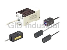
LA-300 SERIES
LED Collimated Beam Sensor
LED collimated beam
type which is as
accurate as a laser
sensor, but much safer.
Conforming to
EMC Directive
Compact size Safe red LED beam Simple beam alignment
Its emitter and receiver are much small- Since a red LED, harmless to your Beam alignment is easy by using the
er compared to those of the amplifier eyes, has been incorporated as the target label (accessory).
built-in type (LA-510). Hence, they can beam source, you are free from strict Further, the 3-stage stability indicators
be installed even in a narrow space laser safety regulations. on the amplifier indicate the incident
inside an automatic assembly machine, Moreover, due to the red LED beam beam level at a glance.
etc. source, the measuring spot is visible,
which makes positioning of the object
Long sensing range type / LA-310
simple.
� Emitter:
Target label
W20�H20�D45 mm
W0.787�H0.787�D1.772 in
� Receiver:
W20�H20�D35 mm
W0.787�H0.787�D1.378 in
Stability indicators
Slim type / LA-305
� Emitter:
W18�H40�D10 mm
W0.709�H1.575�D0.394 in
� Receiver:
W18�H40�D10 mm
W0.709�H1.575�D0.394 in
Two comparative outputs
plus one analog output Span & shift adjustment
In addition to 1 to 5 V analog output, For the analog output, in addition to the span adjustment function, a convenient
two comparative outputs (HIGH, LOW) shift function which enables the analog voltage to be shifted by�0.5 V has been
have been incorporated. incorporated.
Example: To shift the analog voltage from 2.51 V to 3.00 V with a certain amount of beam interruption
Light beam
5.49
After adjustment
External synchronization
5.00
The timing and the effective duration of
Sensing object
1.49
the comparative outputs can be con-
Before adjustment
trolled by an external input. (Either Before adjustment After adjustment 1.00
Darkest condition 1.00 V 1.49 V
edge trigger or gate trigger is selec-
0
table.) Setting condition
2.51 V 3.00 V Interrupted
width
Lightest condition 5.00 V 5.49 V
944
GP-A GP-X LD LA LA-300 HL-T1 LM10 LH-50 HL-C1
MEASUREMENT SENSORS
Magnetic Displacement Light / Thru-beam Type Light / Reflective Type
Emitter
Receiver
Analog output (V)
Lightest
Darkest
POWER
STB SPAN
SHIFT
HIGH
ES
LOW
LA-300
APPLICATIONS
Detecting unseated wafers Inspecting burrs on workpieces Detecting glass bottles
Two sensors inspect vertical and late- If burrs are present, they increase the Even clear glass bottles are reliably
ral displacement of wafers. width of beam interruption. detected.
Wafer
Index table
ORDER GUIDE
Always use the sensor head and the amplifier together as a set.
Sensor heads
Minimum sensing
Appearance Sensing range Sensing width Model No.
Type
object
" "
500 mm 0.1 mm 0.004 in
10 mm 0.394 in
LA-310
19.685 in opaque object
"0.05 mm "0.002 in
300 mm
5 mm 0.197 in
LA-305
opaque object
11.811 in
Always use the sensor head and the amplifier together as a set.
Amplifiers
Accessories
Type • MS-LA3-1 • MS-LA3-2
Appearance Model No. Output
Sensor head Sensor head
mounting bracket for mounting bracket for
NPN open-collector
()()
LA-310 LA-305
transistor
(Comparative outputs)
LA-A1
Analog voltage
• Output voltage 1 to 5 V
PNP open-collector
transistor
LA-A1P (Comparative outputs)
Analog voltage
• Output voltage 1 to 5 V
Four M3 (length 25 mm Four M3 (length 15 mm
0.984 in) pan head screws 0.591 in) screws with
are attached. washers are attached.
OPTIONS
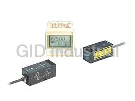
Digital panel controller
• CA2 series
Designation Model No. Description
This is a very small controller which allows
two independent threshold level settings.
• Supply voltage: 24 V DC�10 %
NPN open-collector • No. of inputs: 1 No. (sensor input)
CA2-T2
transistor • Input range: 1 to 5 V DC
• Main functions:
Auto-reference function, zero-adjust function, • CA series
start / hold function, etc.
Digital panel
controller
This is a multi-functional controller having
(Note)
CA-R2 Relay contact
mathematical functions, hold function, etc.
• Supply voltage: 100 to 240 V AC�10 %
• No. of inputs: 2 Nos. (sensor inputs)
NPN open-collector
• Input range: 1 to 5 V DC
CA-T2
transistor
• Power supply for sensor: 12 V DC, 150 mA
• Main functions:
NPN open-collector
Mathematical functions, hold function, auto-
transistor
CA-B2
reference function, zero-adjust function, etc.
With BCD output
Note: If analog voltage output of LA-A1 or LA-A1P is shifted, the input range may be exceeded. In that
case, use CA2-T5 or CA-�5 (input range�10 to�10 V). For further details, refer to p.864l for
the ultra-compact digital panel controller CA2 series, and to p.854l for the digital panel controller
CA series.
945
Long sensing
PNP output NPN output Slim
range
Magnetic Displacement Light / Thru-beam Type Light / Reflective Type
MEASUREMENT SENSORS
GP-A GP-X LD LA LA-300 HL-T1 LM10 LH-50 HL-C1
LA-300
SPECIFICATIONS
Sensor heads
Type Long sensing range Slim
Item Model No. LA-310 LA-305
Applicable amplifiers LA-A1, LA-A1P
Beam width 10 mm 0.394 in 5 mm 0.197 in
Sensing range 500 mm 19.685 in 300 mm 11.811 in
"0.1 mm "0.004 in opaque object "0.05 mm "0.002 in opaque object
Min. sensing object
Repeatability 0.01 mm 0.0004 in or less (perpendicular to sensing axis)
Temperature characteristics 0.1 % F.S. /°C or less 0.2 % F.S. /°C or less
Emission indicator Red LED (lights up when emitting)
Pollution degree
3 (Industrial environment)
Ambient temperature
0 to�40 °C �32 to�104 °F (No dew condensation), Storage:�20 to�70°C �4 to�158 °F
Ambient humidity 35 to 85 % RH, Storage: 35 to 85 % RH
# #
Ambient illuminance Sunlight: 10,000 x at the light-receiving face, Incandescent light: 10,000 x at the light-receiving face
EMC EN 50081-2, EN 50082-2, EN 61000-6-2
Voltage withstandability 1,000 V AC for one min. between all supply terminals connected together and enclosure
Insulation resistance
20 MΩ, or more, with 250 V DC megger between all supply terminals connected together and enclosure
Vibration resistance
10 to 150 Hz frequency, 0.75 mm 0.030 in amplitude in X, Y and Z directions for two hours each
2
Shock resistance 500 m/s acceleration (50 G approx.) in X, Y and Z directions for three times each
Emitting element Red LED (modulated)
Enclosure: Die-cast zinc alloy Enclosure: Heat-resistant ABS
Material
Top face: Aluminum Cover: Heat-resistant ABS, Front cover: Glass
2 2
Cable 0.22 mm 3-core composite cabtyre cable, 2 m 6.562 ft long 0.18 mm 3-core composite cabtyre cable, 2 m 6.562 ft long
Extension up to total 10 m 32.808 ft is possible, for both Extension up to total 10 m 32.808 ft is possible, for both
2 2
Cable extension emitter and receiver, with 0.22 mm , or more, cable. (Shield emitter and receiver, with 0.18 mm , or more, cable. (Shield
wire must be extended with shield wire.) wire must be extended with shield wire.)
Emitter: 110 g approx., Receiver: 100 g approx. Emitter: 70 g approx., Receiver: 70 g approx.
Weight
MS-LA3-1 (Sensor head mounting bracket): 1 set for emitter MS-LA3-2 (Sensor head mounting bracket): 1 set for emitter
Accessories
and receiver, Target label: 2 pcs. and receiver, Target label: 2 pcs.
946
GP-A GP-X LD LA LA-300 HL-T1 LM10 LH-50 HL-C1
MEASUREMENT SENSORS
Magnetic Displacement Light / Thru-beam Type Light / Reflective Type
Environmental resistance
LA-300
SPECIFICATIONS
Amplifiers
Type NPN output type PNP output type
Item Model No. LA-A1 LA-A1P
Applicable sensor heads LA-310, LA-305
Supply voltage 12 to 24 V DC�10 % Ripple P-P 10 % or less
Current consumption 120 mA or less (including sensor heads)
NPN open-collector transistor PNP open-collector transistor
• Maximum sink current: 100 mA • Maximum source current: 100 mA
Comparative outputs • Applied voltage: 30 V DC or less • Applied voltage: 30 V DC or less
(HIGH, LOW) (between comparative output and 0 V) (between comparative output and �V)
• Residual voltage: 1.5 V or less (at 100 mA sink current) • Residual voltage: 1.5 V or less (at 100 mA source current)
0.5 V or less (at 16 mA sink current) 0.5 V or less (at 16 mA source current)
Utilization category DC-12 or DC-13
Response time 0.5 ms or less
HIGH output: ON when the received beam level is equal to or lower than HIGH (Over-dark) level
Output operation
LOW output: ON when the received beam level is equal to or higher than LOW (Under-dark) level
Short-circuit protection Incorporated
Analog voltage
Analog output • Output voltage: 1 V (Darkest) to 5 V (Lightest)
• Output impedance: 75 Ω
Slew rate 8 V/ms or more
Temperature characteristics 0.05 % F.S. /°C or less
External synchronization Incorporated (Active-Low, either gate trigger or edge trigger is selectable)
Green LED (lights up when the power is ON)
Power
Three green LEDs (light up in three stages in proportion to the amount of beam received)
Stable incident beam
Two orange LEDs (light up when High and Low comparative outputs are ON, respectively)
Operation
Green LED (lights up when the external synchronization input is effective, i.e., LOW)
External synchronization
Span 15-turn adjuster sets the span for the analog output voltage
Shift 15-turn adjuster sets the offset for the analog output voltage
15-turn adjuster sets the HIGH output threshold level (Over-dark level)
HIGH (Over-dark) level
15-turn adjuster sets the LOW output threshold level (Under-dark level)
LOW (Under-dark) level
3 (Industrial environment)
Pollution degree
Ambient temperature 0 to�50 °C �32 to�122 °F (No dew condensation), Storage:�20 to�70°C �4 to�158 °F
Ambient humidity 35 to 85 % RH, Storage: 35 to 85 % RH
EMC EN 50081-2, EN 50082-2, EN 61000-6-2
1,000 V AC for one min. between all supply terminals connected together and enclosure
Voltage withstandability
20 MΩ, or more, with 250 V DC megger between all supply terminals connected together and enclosure
Insulation resistance
10 to 150 Hz frequency, 0.75 mm 0.030 in amplitude in X, Y and Z directions for two hours each
Vibration resistance
2
Shock resistance 500 m/s acceleration (50 G approx.) in X, Y and Z directions for three times each
Material Enclosure: Heat-resistant ABS, Terminal cover: Heat-resistant ABS, Front cover: Polycarbonate
2 2
0.22 mm (shield wire: 0.15 mm ) 7-core composite cabtyre cable, 2 m 6.562 ft long
Cable
2 2
Extension up to total 50 m 164.042 ft is possible with 0.22 mm , or more, cable. (Shield wire must be extended with 0.15 mm , or more, shield wire.)
Cable extension
200 g approx.
Weight
Adjusting screwdriver: 1 pc.
Accessory
Note: This is a CE conformity product complying with EMC Directive. The harmonized standard with regard to immunity that applies to this product is
EN 61000-6-2 and the following conditions must be met to conform to that standard.
Conditions
• The amplifier should be connected less than 10 m 32.808 ft from the power supply.
• The signal line to connect with the amplifier should be less than 30 m 98.425 ft.
The EN 50082-2 that previously applied to the products for conforming to EMC Directive was replaced by EN 61000-6-2 starting April 1st, 2002.
947
Environmental resistance Adjusters Indicators
Magnetic Displacement Light / Thru-beam Type Light / Reflective Type
MEASUREMENT SENSORS
GP-A GP-X LD LA LA-300 HL-T1 LM10 LH-50 HL-C1
LA-300
I/O CIRCUIT AND WIRING DIAGRAMS
LA-A1
NPN output type
I/O circuit diagram
Terminal No.
Amplifier
LA-A1 Color code
Color code
Sensor heads
�V (Brown) D1
(Brown) �V
LA-310, LA-305
9
Receiver
(Black) Comparative
Load
0 V (Blue) (Black) output (HIGH)
8
Tr1
�
Load 12 to 24 V DC
SIG. 100 mA max.
ZD1
�10 %
(White) �
(White) Comparative output (LOW)
7 Tr2
100 mA max.
ZD2
(Blue) 0 V
Shield 6
m1
75 Ω
�V (Brown)
�
(Gray) Analog output (�)
5 Non-voltage contact or
�
Emitter
NPN open-collector transistor
ZD3
0 V (Blue)
4 (Shield) Analog output (�)
SYNC. or
(Orange / Violet)
D2 4.7 kΩ
(Pink) External synchronization input ES�
3
• Voltage between ES� and ES�
m1
Low: 0 to 1 V
Shield
2 High:�V or open
(Pink / Blue) External synchronization input ES�
Notes: 1) When ES�(pink) and ES�(pink / blue) of external synchronization
Amplifier
Sensor heads Users’ circuit
internal circuit
input are connected, both HIGH and LOW comparative outputs are
triggered in the mode selected by the external synchronization
selection switch.
If the external synchronization function is not used, short-circuit
Symbols ... D1: Reverse supply polarity protection diode
ES� and ES� and set the external synchronization selection
D2: Input protection diode
switch to gate trigger.
ZD1, ZD2, ZD3: Surge absorption zener diode
Notes: 2) To use the analog output (gray), choose a device with an input
Tr1, Tr2: NPN output transistor
impedance of 1 MΩ, or more, and connect the shield wire of the
analog output to 0 V (common input) of the device.
Notes: 3) Insulate all unused wires individually to avoid miscontact.
LA-A1P
PNP output type
I/O circuit diagram
Terminal No.
Amplifier
LA-A1P
Color code Color code
Sensor heads
�V (Brown) (Brown)�V
LA-310, LA-305
9
ZD1 ZD2
Receiver
100 mA max.
0 V(Blue)
Tr1
8
�
12 to 24 V DC
SIG. (Black) Comparative output (HIGH)
�10 %
�
(White) 100 mA max.
Tr2
7
Load
Load
(White) Comparative
D1
(White) output (Low)
Shield 6
0 V (Blue)
m1
75 Ω
�V (Brown)
�
(Gray) Analog output (�) Non-voltage contact or
5
�
Emitter
PNP open-collector transistor
ZD3
0 V (Blue)
4 (Shield) Analog output (�)
or
SYNC.
(Orange / Violet) 4.7 kΩ
(Pink / Blue) External synchronization input ES�
3
• Voltage between ES� and ES�
m1
Low: 0 to 1 V
10 kΩ
D2
High:�V or open
Shield 2
(Pink) External synchronization input ES�
Notes: 1) When ES�(pink / blue) and ES�(pink) of external synchronization
Amplifier
Sensor heads Users’ circuit
internal circuit
input are connected, both HIGH and LOW comparative outputs are
triggered in the mode selected by the external synchronization
selection switch.
If the external synchronization function is not used, short-circuit
Symbols ... D1: Reverse supply polarity protection diode
ES� and ES� and set the external synchronization selection
D2: Input protection diode
switch to gate trigger.
ZD1, ZD2, ZD3: Surge absorption zener diode
Notes: 2) To use the analog output (gray), choose a device with an input
Tr1, Tr2: PNP output transistor
impedance of 1 MΩ, or more, and connect the shield wire of the
analog output to 0 V (common input) of the device.
Notes: 3) Insulate all unused wires individually to avoid miscontact.
948
GP-A GP-X LD LA LA-300 HL-T1 LM10 LH-50 HL-C1
MEASUREMENT SENSORS
Magnetic Displacement Light / Thru-beam Type Light / Reflective Type
Main circuit Main circuit
LA-300
I/O CIRCUIT AND WIRING DIAGRAMS
Wiring diagram
Receiver Emitter
Cable
Black Gray
Connect color-coded wires in accordance with the table below.
Color code
The receiver wires should be connected on the upper termi-
nal block and the emitter wires on the lower terminal block.
Emitter Receiver
9 8 7 6 5 4 3 2
Terminal No. Color code Terminal No. Color code
2 Shield 6 Shield
3 Orange / Violet 7 White
Lower terminal block
5 4 3 2 1
for the emitter
4 Blue 8 Blue
Upper terminal block
9 8 7 6
for the receiver
5 Brown 9 Brown
POWER POWER
Note: Do not connect any wire to the terminal 1.
STB STB
SPAN SPAN
SHIFT SHIFT
SENSING CHARACTERISTICS (TYPICAL)
LA-310
Long sensing range type
Correlation between transverse Correlation between interrupted Correlation between ambient tempera-
deviation and output voltage beam width and output voltage ture and output voltage variation rate
8 8 2
500 mm 19.685 in
500 mm 19.685 in
Receiver
Emitter � Receiver
Emitter
6 # 6 1
Amplifier
# �
Sensor
Sensing object
heads
4 4 0
2
2 �1
0
0 �2
20 10 010 20 �10 �5 05 10 0 10 20 30 40 50
0.787 0.394 0.394 0.787 �0.394 �0.197 0.197 0.394 32 50 68 86 104 122
Left Center Right Screening edge position Ambient
temperature (°C °F)
Deviation ?(mm in) ?(mm in)
LA-305
Slim type
Correlation between transverse Correlation between interrupted Correlation between ambient tempera-
deviation and output voltage beam width and output voltage ture and output voltage variation rate
2
8 8
300 mm 11.811 in
Receiver
Sensor
�
heads
1
6 6
�
Emitter #
Sensing object
Amplifier
4 4 0
300 mm
11.811 in
2 2 �1
#
Receiver
Emitter
0 0
�2
0 10 20 30 40 50
10 5 05 10 �10 �5 05 10
32 50 68 86 104 122
0.394 0.197 0.197 0.394 �0.394 �0.197 0.197 0.394
Ambient
Left Center Right Screening edge position
temperature (°C °F)
?(mm in)
Deviation ?(mm in)
949
Output voltage (V)
Output voltage (V)
Brown
Blue
Output voltage (V)
Output voltage (V)
White
Shield
Brown
Blue
Orange / Violet
Shield
Output voltage variation rate (%)
Output voltage variation rate (%)
Magnetic Displacement Light / Thru-beam Type Light / Reflective Type
MEASUREMENT SENSORS
GP-A GP-X LD LA LA-300 HL-T1 LM10 LH-50 HL-C1
LA-300
PRECAUTIONS FOR PROPER USE
Beam alignment
This product is not a safety sensor. Its use is not
• Make sure that at least one stability indicator lights up when
intended or designed to protect life and prevent body
you supply power to the amplifier connected with sensor
injury or property damage from dangerous parts of
heads. While aligning sensor heads, if more stability
machinery. It is a normal object detection sensor.
indicators light up, more reliable detection can be obtained.
Mounting • Beam alignment should be performed prior to any adjust-
ments on the amplifier.
Sensor heads
• If the bottom face and the side face of the emitter and the
• The projected LED beam has a directionality. Hence, take
receiver are mounted on the same plane surfaces, or if the
care of emitter and receiver mounting direction.
front faces of the emitter and the receiver of LA-305 are kept
parallel and their top face and side face are mounted on the
LA-310 LA-305
same plane surfaces, beam alignment need not be done.
Receiver
• If mounting is not possible on the same plane surfaces,
Receiver
Emitter
2-mounting affix the target label (accessory) on the front surface of the
holes
receiver and adjust so that the emitted beam is incident at
the center of the crosshair. After the alignment, peel off the
Emitter
Receiver
target label.
• If either sensor head moves out of position, do the beam
alignment and then the amplifier adjustment also again.
Emitter
Receiver
LA-310 LA-305
Receiver
Aperture
Target label
Aperture
• The tightening torque should be 0.5 N�m or less.
Target label
LA-310 LA-305
• To obtain optimum beam alignment, use a voltmeter and
adjust the position to obtain the peak analog output signal
from the amplifier.
Functional description
Amplifier Sensor head / LA-310 (Emitter)
1 7
POWER
STB SPAN 8
Sensor head mounting bracket 2
Sensor head mounting bracket
MS-LA3-2 (Accessory) (Note)
SHIFT
9
MS-LA3-1 (Accessory)
3
A
HIGH
ES
5
Note: When carrying out high accuracy sensing with LA-305, install the LOW
6
mounting bracket on the front face as shown in the above figure.
0
4
Amplifier
Frequently asked questions
What makes Elite.Parts unique?

What kind of warranty will the LA-A1P have?
Which carriers does Elite.Parts work with?
Will Elite.Parts sell to me even though I live outside the USA?
I have a preferred payment method. Will Elite.Parts accept it?
Why buy from GID?

Quality
We are industry veterans who take pride in our work

Protection
Avoid the dangers of risky trading in the gray market

Access
Our network of suppliers is ready and at your disposal

Savings
Maintain legacy systems to prevent costly downtime

Speed
Time is of the essence, and we are respectful of yours
Related Products
Request a Quote

The quote request has been received
Close

Facing challenges or have inquiries? Feel free to contact us!
Call Us +1-469-283-2440
What they say about us
FANTASTIC RESOURCE
One of our top priorities is maintaining our business with precision, and we are constantly looking for affiliates that can help us achieve our goal. With the aid of GID Industrial, our obsolete product management has never been more efficient. They have been a great resource to our company, and have quickly become a go-to supplier on our list!
Bucher Emhart Glass
EXCELLENT SERVICE
With our strict fundamentals and high expectations, we were surprised when we came across GID Industrial and their competitive pricing. When we approached them with our issue, they were incredibly confident in being able to provide us with a seamless solution at the best price for us. GID Industrial quickly understood our needs and provided us with excellent service, as well as fully tested product to ensure what we received would be the right fit for our company.
Fuji
HARD TO FIND A BETTER PROVIDER
Our company provides services to aid in the manufacture of technological products, such as semiconductors and flat panel displays, and often searching for distributors of obsolete product we require can waste time and money. Finding GID Industrial proved to be a great asset to our company, with cost effective solutions and superior knowledge on all of their materials, it’d be hard to find a better provider of obsolete or hard to find products.
Applied Materials
CONSISTENTLY DELIVERS QUALITY SOLUTIONS
Over the years, the equipment used in our company becomes discontinued, but they’re still of great use to us and our customers. Once these products are no longer available through the manufacturer, finding a reliable, quick supplier is a necessity, and luckily for us, GID Industrial has provided the most trustworthy, quality solutions to our obsolete component needs.
Nidec Vamco
TERRIFIC RESOURCE
This company has been a terrific help to us (I work for Trican Well Service) in sourcing the Micron Ram Memory we needed for our Siemens computers. Great service! And great pricing! I know when the product is shipping and when it will arrive, all the way through the ordering process.
Trican Well Service
GO TO SOURCE
When I can't find an obsolete part, I first call GID and they'll come up with my parts every time. Great customer service and follow up as well. Scott emails me from time to time to touch base and see if we're having trouble finding something.....which is often with our 25 yr old equipment.
ConAgra Foods