

 Manufacturers
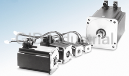
PACIFIC SCIENTIFIC Servo Motor
Description
Pacific Scientific Servo Motors
Part Number
Servo Motor
Price
Request Quote
Manufacturer
PACIFIC SCIENTIFIC
Lead Time
Request Quote
Category
PRODUCTS - S
Datasheet

Extracted Text
HIGH PERFORMANCE SERVO MOTORS PMA Series N • 5 Frame Sizes 55, 70, 115, 142 and 190mm Square • 0.21 - 54 Nm Continuous Torque Range PMB Series • 3 Frame Sizes • Size 17, NEMA 23 and 34 Mounts • 0.22 - 4.8 Nm Continuous Torque Range S Series • 2 Frame Sizes • Available in NEMA 23 and 34 Mounts • 0.5 - 6.6 Nm Continuous Torque Range R Series N • 5 Frame Sizes 2, 3.25, 4.25, 5.75 and 7.5 Inches Square • Explosion Proof Models Available • 0.32 - 50 Nm Continuous Torque Range March, 2001 PACIFIC SCIENTIFIC BRUSHLESS SERVO MOTORS A Full Spectrum of Powerful PMB Series R Series Brushless Servomotors The PMB Series of brushless R Series servomotors offer the Pacific Scientific servomotors are servomotors introduces an IP40 highest torque-to-inertia ratios in built for long, maintenance-free construction motor in three frames; the industry. Engineered for the service life. Once installed, you size 17 and NEMA 23 & 34 to address highest dynamic response available, probably won't have to look at them your need for a high-performance these motors come in five frame motor in higher-volume applications. sizes – both NEMA and metric With a continuous rated torque mountings. The R Series covers a range from 0.22 to 4.8 Nm, the continuous rated torque range from cost-effective PMB motors 0.32 to 50 Nm. complement our full line of servos. Pacific Scientific Digital Brushless Servo Drives – Harness the Power When these motors are combined again. The motors in the following with Pacific Scientific's broad pages feature Neodymium-iron- offering of digital brushless servo boron or Samarium cobalt magnets drives, they offer a cost-effective, for the highest torque-to-inertia high-performance solution ratios possible. Anti-cog stator that's tough to beat. The systems designs deliver smooth low-speed package motors shown on pages performance. 5 to 9 are only the tip of the iceberg. All of the brushless servomotors PMA Series are customizable — often with S Series The PMA Series of brushless minimal impact on delivery The S Series brushless servomotors servomotors delivers a times. From feedback options to offer continuous torques from 0.5 to comprehensive line of rugged, cost- application-specific windings, we 6.6 Nm. Available in two frame sizes effective servomotors. Covering can help with your servo needs. with both metric and NEMA 23 & 34 frame sizes from 55mm square to mounting faces, these compact 190mm square and a continuous Pacific Scientific's SC/SCE900 series motors squeeze a lot of torque into a rated torque range of 0.21 to 54 Nm, brushless servo drives continue to small package. these motors offer an economic be the flagship of our servo drives. means to satisfy the requirements of No other brushless servo drive offers your application. Standard IP65 higher performance. No other drive sealing and the availability of IP67 offers broader functionality. washdown duty as an option on selected models allows the PMA The PC800 family of brushless servo Series to stand up to the rigors of drives offers a cost-effective, small the factory floor. Global certifications drive with the best lead time in the and input voltages on most models industry. to 650 volts assure your machine's acceptance worldwide. SERVO MOTORS BRUSHLESS SERVO MOTORS FEATURES & BENEFITS The PC3400 Series of brushless FEATURES BENEFITS servo drives brings to you a family of PMA/S/R Series Motors cost-effective, easy-to-use, intelligent servos from the leaders in service Rugged Brushless Construction Eliminates brush replacement maintenance Stands up to the rigors of the factory floor and performance. High torque over wide speed range Improved machine throughput Smart technology. Motion Anti-cog motor design Smooth low-speed operation simplified. These systems are a prime example IP65 TENV construction standard Withstands rigorous environments of Pacific Scientific's commitment Two year warranty Quality and reliability for reduced machine to offer you smart technology -— downtime the highest-performance products available, customized to suit Class H insulation Longer life for reduced machine downtime your applications, and backed by Overtemperature thermistor Protection against motor damage unmatched customer support and quality. We want to help make your Global approvals and agency recognition Eases recognition process for a machine job easier. For more information, Multiple feedback options Allows numerous control methods contact our Customer Response Center at (815) 226-3100, or visit Brake option Improved machine safety our website at www.pacsci.com. PMA/S Series Motors IP67 protection on selected PMA models Withstands washdown Neodymium-iron-boron magnets Maximum performance, maximum value High quality Interconnectron connectors Faster installation and maintenance High voltage models available Improved application flexibility S/R Series Motors NEMA mounting available Improved application flexibility Steel bearing inserts Longer life for reduced machine downtime R Series Motors Fast acceleration, improved dynamic High torque-to-inertia ratios response PMB Series Motors ® MS or AMP mini Mate-N-Lock Improved application flexibility connector options IP40 Construction Improved cost-effectiveness for higher volume applications www.pacsci.com 1 SELECTION OVERVIEW Typical Maximum Continuous Rated Torque (Nm) and Speed (rpm) Torque Range Speed Range Page 48V dc bus Brushless PMB1 0.22 - 0.50 700 - 6,450 17 PMB Servomotors PMB2 0.61 - 1.10 600 - 1,300 18 Typical Maximum Continuous Rated Torque (Nm) and Speed (rpm) Torque Range Speed Range Page PMA1 0.21 - 0.60 7,000 - 9,000 11 PMA2 0.50 - 2.2 3,000 - 6,450 12 PMA PMA4 3.4 - 9.9 600 - 4,700 13 PMA5 8.8 - 20.5 900 - 3,450 14 PMA6 24.5 - 48.5 950 - 1,750 15 PMB1 0.14 11,000 17 240V ac, 320V dc bus Brushless PMB PMB2 0.45 - 1.40 4,400 - 10,000 18 Servomotors PMB3 1.62 - 4.84 1,300 - 6,000 19 S20 0.32 - 1.5 3,400 - 12,500 21 S Series S30 1.9 - 6.4 1,300 - 3,900 22 R20 0.17 - 1.0 3,000 - 11,000 24 R30 0.76 - 3.7 1,700 - 7,000 26 R40 3.6 - 7.3 1,500 - 5,300 27 R Series R60 4.4 - 17.6 1,400 - 6,000 28 R80 10.1 - 48.6 1,200 - 4,000 29 R30P 0.62 - 3.0 1,900 - 7,000 30 R Series Explosion Proof R60P 3.6 - 14.4 1,500 - 6,000 31 Typical Maximum Continuous Rated Torque (Nm) and Speed (rpm) Torque Range Speed Range Page PMA4 3.0 - 9.5 1,600 - 6,000 13 400V ac, 560V dc bus PMA5 7.2 - 19.0 1,900 - 4,200 14 PMA Brushless PMA6 19.0 - 43.8 1,350 - 3,300 15 Servomotors S30 4.0 - 4.3 3,000 22 S Series Typical Maximum Continuous Rated Torque (Nm) and Speed (rpm) Torque Range Speed Range Page PMA4 2.6 - 9.3 2,100 - 6,800 13 480V ac, 640V dc bus PMA5 6.8 - 18.6 2,200 - 4,750 14 PMA Brushless PMA6 17.5 - 42.2 1,600 - 3,800 15 Servomotors S30 3.6 - 3.9 3,600 - 3,900 22 S Series 2 www.pacsci.com SERVO MOTORS INDEX How to use this Product Overview Inside front cover selection guide Features 1 Use the selection overview on page 2 to identify motors Selection Overview 2 available to fit your system voltage, torque and speed How to Use This Selection Guide 3 requirements. Detailed system System Performance Data combinations with ratings are shown on pages 5 - 9. The table How to Construct a System 4 of contents to the right will help you find more information on System Performance Data, 48V dc bus 5 each motor family. System Performance Data, 240V ac, 320V dc bus 5 System Performance Data, 400V ac, 560V dc bus 8 Information on the Pacific System Performance Data, 480V ac, 640V dc bus 9 Scientific drives mentioned in the following pages can be PMA Series Brushless Servomotors 10 found in the Pacific Scientific publication “High Performance • Model Number Codes Servo Drives.” A Copy of this • Ratings and Characteristics publication can be obtained by • Metric Mount calling Pacific Scientific, or you can get one by visiting our PMB Series Brushless Servomotors 16 website at www.pacsci.com • Model Number Codes • If you are already familiar • Ratings and Characteristics with these motors and their available options, refer to the • NEMA Mount Model Number Codes on pages S Series Brushless Servomotors 20 10, 16, 20, 23 and 25 to verify coded information prior to • Model Number Codes ordering. • Ratings and Characteristics • If you are not familiar with • Metric Mount these motors and their available options, refer to R20 Series Round Brushless Servomotors 23 the index at the right. Note that each frame size is covered • Model Number Codes individually and the technical • Ratings and Characteristics data (last) applies to all motors. • Metric Mount Construct a model number after all the technical R Series Brushless Servomotors 25 parameters, including options, are determined. • Model Number Codes • Ratings and Characteristics Our sizing and selection ™ program, Optimizer 3.0 can be • Metric Mount helpful in determining the correct Brushless Servomotor Feedback Combinations 32 motor for your application. Input the parameters for your specific Brushless Servomotor Brake Options 38 application and specify your drive voltage, current and output type Brushless Servomotor Connection Options 39 and Optimizer will find the motors that fit the bill. Ask for Cabling and Accessories 43 your copy today. www.pacsci.com 3 HOW TO BUILD A SERVO DRIVE & MOTOR SYSTEM Torque (Nm) SYSTEM VOLTAGE LINE Speed (rpm) NL NO LOAD System torque/speed information on the following pages are designed to help you select the optimum brushless servo motor/controller combination. The nominal values in this data illustrate performance for the recommended motor/controller systems. DRIVE & MOTOR PERFORMANCE CURVES The performance characteristics of controller can produce for a limited time, or detailed torque/speed information, a brushless servo system (motor/ the maximum rated current for the motor, take a look at our sizing and selection ™ controller combination) are described by whichever is less. Refer to the Rating Data program, Optimizer 3.0. With Optimizer’s a torque/speed operating envelope. As on the pages that follow. sine/trapezoidal conversion algorithm, you shown above, the shaded areas of the NOTE: higher torque levels may be can see how our motors pair up with a curve indicate the continuous duty and achievable at higher power levels. Consult trapezoidal drive, too. Call Pacific Scientific intermittent duty zones of the system. Pacific Scientific for more details. at 815-226-3100 to get your free copy today, The system voltage line is set by the or visit our website at www.pacsci.com. Continuous Duty Zone voltage rating of the controller, the line The continuous duty zone is bordered Additional References voltage applied and the motor winding. by the maximum continuous torque On the pages that follow, each individual Operation in the intermittent zone must line up to the rated speed of the motor. system has reference points in a table. be limited to a duty cycle that will produce The continuous torque line is set by either In addition to rating points for peak (T ) PS an RMS system torque falling within the the motor’s maximum rated temperature, and continuous torque (T ) ratings at CS continuous duty area. The RMS torque or the controller’s rated continuous current stall, each system has: value is defined by the magnitude of the output, whichever is less. The system • Rated speed (W ) R intermittent torque and the percentage of voltage line is set by the voltage rating of • Continuous torque at rated speed (T ) CR the time spent at that torque. the controller, the line voltage supplied, and • Peak torque at rated speed (T ) PR the motor winding. Zero - Peak, or RMS? • Motor unloaded speed (W ) NL The system can operate on a continuous basis Current brushless drive technology uses To construct a curve, follow the guidelines anywhere within this area, assuming the motor a sinusoidal output. Pacific Scientific rates presented in the generic curve above. temperature is 40°C or less, ambient. Refer to its systems using RMS values to accurately System rated speeds and torques are the Test Conditions on the pages that follow. reflect system performance operating with a based on the intersection of the system sinusoidal waveform. voltage line and the peak current line. Intermittent Duty Zone Older published ratings were based on Differing peak currents will impact rated The intermittent duty zone is bordered 0 - peak values, using a trapezoidal waveform. system speeds. by the peak torque line and the system The points are provided for reference voltage line. Optimizer 3.0 for use in comparing and sizing systems. The peak torque line is set by either the For more information on any motor on the controller’s peak current rating, which the following pages, or to take a closer look at 4 www.pacsci.com SERVO MOTORS Torque (Nm) SYSTEMS PERFORMANCE DATA SYSTEM VOLTAGE LINE continuous duty intermittent duty Speed (rpm) NL NO LOAD ➀ ➁ RECOMMENDED MOTOR/DRIVE SYSTEMS, 48V dc bus Peak Peak Cont. Cont.➃Inertia Stall Rated Stall Rated Rated Inductance No-Load Cont. Stall Current at J 2 -3 Servo Servo Torque Torque Torque Torque Speed Line-Line Speed Current Peak Torque kgm x 10 ➀➁➂Motor Drive T T T T W 2 L PS PR CS CR R W I I NL (lb.-in.-S CS PS ➄Model Model Nm (lb.-in.) Nm (lb.-in.) Nm (lb.-in.) Nm (lb.-in.) rpm -3 mH rpm A A x 10 ) RMS RMS PMB Series motors with PC340XD Drives PMB11B PC3402 0.45 (4.0) 0.45 (4.0) 0.22 (2.0) 0.22 (2.0) 1,000 5,000 2.4 5.0 0.005 (0.045) 2.5 PMB11D PC3405 0.45 (4.0) 0.44 (3.9) 0.22 (2.0) 0.20 (1.8) 6,450 10,000 4.8 10.0 0.005 (0.045) 0.6 PMB12B PC3402 0.80 (7.1) 0.79 (7.0) 0.40 (3.5) 0.40 (3.5) 700 2,900 2.5 5.0 0.009 (0.079) 3.3 PMB12D PC3405 0.83 (7.3) 0.82 (7.3) 0.40 (3.5) 0.38 (3.3) 3,500 5,600 4.7 10.0 0.009 (0.079) 0.9 PMB13D PC3405 1.11 (9.8) 1.10 (9.7) 0.55 (4.9) 0.50 (4.4) 2,350 4,150 4.8 10.0 0.013 (0.113) 1.1 PMB21D PC3405 1.27 (11.2) 1.26 (11.2) 0.64 (5.7) 0.61 (5.4) 1,300 3,600 5.0 10.0 0.023 (0.201) 1.2 PMB22D PC3405 2.2 (19.5) 2.2 (19.5) 1.11 (9.8) 1.10 (9.7) 600 2,150 5.0 10.0 0.044 (0.385) 1.5 ➀See page 4 for definitions of ratings.➂48V dc figures shown for reference. Operation available from ➃DC drives offer operation with encoder feedback only. Inertia 18-74V dc. figures include encoder feedback.➁Peak torque ratings are for 1 second. ➄Each system requires one feedback and one motor power cable. ➀ RECOMMENDED MOTOR/DRIVE SYSTEMS, 240V ac, 320V dc bus Peak Peak Cont. Cont.➆Inertia Stall Rated Stall Rated Rated Inductance No-Load Cont. Stall Current at J Servo Servo Torque Torque Torque Torque Speed 2 -3 Line-Line Speed Current Peak Torque kgm x 10 ➀➅Motor Drive T T T T W 2 L W PS PR CS CR R I I (lb.-in.-S NL CS PS ➇Model Model Nm (lb.-in.) Nm (lb.-in.) Nm (lb.-in.) Nm (lb.-in.) rpm -3 mH rpm A A x 10 ) RMS RMS PMA Series motors with PC8xx and SC9xx Drives PMA11A PC8x2, SC9x2/SCE9x2➁1.4 (12.4) 1.4 (12.4) 0.26 (2.3) 0.22 (1.9) 6,600 12,900 0.96 5.3 0.012 (0.102) 7.1 PMA12A PC8x2, SC9x2/SCE9x2➁1.7 (14.8) 1.7 (14.7) 0.6 (5.3) 0.47 (4.2) 8,500 10,800 1.88 5.3 0.019 (0.164) 4.3 PMA13B PC8x2, SC9x2/SCE9x2➁1.7 (15.3) 1.7 (15.2) 0.9 (8.0) 0.6 (5.3) 9,000 10,600 2.73 5.3 0.026 (0.226) 2.7 PMA21B PC8x2, SC9x2/SCE9x2➁1.8 (16.3) 1.8 (16.2) 0.63 (5.6) 0.50 (4.4) 6,050 9,250 1.72 5.3 0.022 (0.19) 10.5 PMA22B PC8x3, SC9x3➁4.7 (42.0) 4.7 (41.9) 1.3 (11.5) 1.1 (9.4) 4,650 7,100 2.65 10.6 0.038 (0.34) 7.4 PMA22B PC8x2, SC9x2/SCE9x2➁2.6 (22.7) 2.5 (22.5) 1.3 (11.5) 1.0 (8.9) 5,750 7,100 2.65 5.3 0.038 (0.34) 7.4 PMA23B PC8x2, SC9x2/SCE9x2➁3.9 (34.2) 3.9 (34.1) 2.0 (17.7) 1.6 (14.6) 3,600 4,700 2.7 5.3 0.055 (0.49) 6.8 PMA23C PC8x3➁5.9 (52.4) 5.9 (52.2) 2.0 (17.7) 1.6 (14.2) 4,200 5,850 3.4 10.6 0.055 (0.49) 10.6 PMA23D PC8x4➁7.3 (64.6) 7.3 (64.3) 2.0 (17.7) 1.4 (12.3) 6,400 8,750 5.0 20.0 0.055 (0.49) 3.0 PMA23D SC9x3➁4.2 (36.8) 4.1 (36.6) 2.0 (17.7) 1.3 (11.5) 7,400 8,750 5.0 10.6 0.055 (0.49) 3.0 PMA24C PC8x3➁7.9 (70.2) 7.9 (70.9) 2.6 (23.0) 2.2 (19.5) 3,000 4,350 3.3 10.6 0.072 (0.64) 8.9 PMA24D PC8x4➁9.5 (84.1) 9.5 (83.8) 2.6 (23.0) 1.9 (17.2) 4,950 6,950 5.3 21.2 0.072 (0.64) 3.5 PMA24D SC9x3➁5.1 (45.3) 5.1 (45.0) 2.6 (23.0) 1.8 (16.1) 5,850 6,950 5.3 10.6 0.072 (0.64) 3.5 PMA42M PC8x2, SC9x2/SCE9x2➁7.7 (67.9) 7.6 (67.7) 4.1 (36.3) 3.9 (34.5) 1,600 2,350 2.8 5.3 0.36 (3.2) 26.0 PMA42N PC8x3➁11.3 (99.9) 11.2 (99.6) 4.0 (35.4) 3.8 (33.6) 1,950 3,100 3.6 10.6 0.36 (3.2) 14.3 PMA42P SC903➁9.1 (80.4) 9.0 (79.9) 4.1 (36.3) 3.6 (31.9) 2,950 4,000 4.7 10.6 0.36 (3.2) 8.9 PMA42Q PC8x4➁12.6 (111) 12.5 (111) 4.1 (36.3) 3.4 (30.1) 3,800 5,450 6.5 21.2 0.36 (3.2) 4.7 PMA43N PC8x3➁16.9 (149) 16.8 (149) 5.9 (52.2) 5.8 (51.3) 1,250 2,050 3.6 10.6 0.52 (4.6) 20.0 PMA43P SC903➁13.8 (122) 13.8 (122) 6.1 (54.0) 5.6 (49.6) 1,850 2,600 4.6 10.6 0.52 (4.6) 13.0 PMA43Q PC8x4➁17.3 (153) 17.2 (152) 6.0 (53.2) 5.2 (46.0) 3,000 4,050 7.1 21.2 0.52 (4.6) 5.3 PMA43R SC904➁12.6 (112) 12.5 (111) 6.1 (54.0) 4.5 (39.8) 4,700 5,650 10.1 21.2 0.52 (4.6) 2.7 PMA44N PC8x3➁23.3 (206) 23.2 (206) 8.2 (72.6) 7.9 (70.0) 850 1,550 3.6 10.6 0.68 (6.0) 27.0 PMA44P PC8x3➁15.9 (141) 15.9 (140) 8.0 (71.3) 7.4 (65.5) 1,750 2,250 5.3 10.6 0.68 (6.0) 12.4 PMA44Q PC8x4➁23.2 (205) 23.1 (205) 8.1 (71.6) 7.3 (64.4) 2,100 3,000 7.1 21.2 0.68 (6.0) 7.1 PMA44R SC904➁17.0 (150) 16.9 (149) 8.2 (72.6) 6.7 (59.3) 3,450 4,200 10.1 21.2 0.68 (6.0) 3.6 PMA45N PC8x3➁29.0 (256) 28.9 (256) 10.2 (90.3) 9.9 (87.6) 600 1,200 3.6 10.6 0.84 (7.4) 33.0 PMA45Q PC8x4➁29.3 (259) 29.2 (258) 10.2 (90.3) 9.4 (83.2) 1,650 2,350 7.1 21.2 0.84 (7.4) 8.7 PMA45R SC904➁21.3 (189) 21.2 (188) 10.2 (90.3) 8.9 (78.8) 2,700 3,300 10.0 21.2 0.84 (7.3) 4.4 PMA53Q PC8x4➁26.9 (238) 26.8 (237) 10.5 (92.9) 9.6 (85.0) 1,300 2,250 6.8 21.2 1.92 (17.0) 15.0 PMA53R SC904➁20.6 (182) 20.5 (181) 10.5 (92.9) 8.8 (77.9) 2,350 3,200 9.7 21.2 1.92 (17.0) 7.2 PMA54Q PC8x4➁34.1 (302) 34.1 (301) 13.5 (120) 12.4 (110) 1,200 1,800 7.1 21.2 2.49 (22.0) 16.0 PMA54R SC904➁24.7 (219) 24.6 (218) 13.5 (120) 11.6 (103) 2,100 2,700 10.6 21.2 2.49 (22.0) 7.1 ➄Peak torque ratings are for .5 second.➀See page 4 for definitions of ratings.➆Includes resolver feedback inertia. ➅Rated speed is provided for operation on 240V ac 3-phase line. ➇Each system requires one feedback and one motor power cable.➁Peak torque ratings are for 5 seconds. Reduce to approximately 85% for 240V ac 1-phase line operation ➈Characteristics shown with drive default parameters limited to 2.5x➂Peak torque ratings are for 2 seconds. and to 40% for 120V ac 1-phase line operation. the motor’s continuous rating. Higher peak system performance➃Peak torque ratings are for 1 second. available. Contact the factory. www.pacsci.com 5 Torque (Nm) SYSTEMS PERFORMANCE DATA SYSTEM VOLTAGE LINE continuous duty intermittent duty Speed (rpm) NL NO LOAD ➀ RECOMMENDED MOTOR/DRIVE SYSTEMS, 240V ac, 320V dc bus continued Peak Peak Cont. Cont.➆Inertia Stall Rated Stall Rated Rated Inductance No-Load Cont. Stall Current at J 2 -3 Servo Servo Torque Torque Torque Torque Speed Line-Line Speed Current Peak Torque kgm x 10 ➀➅Motor Drive T T T T W 2 L PS PR CS CR R W I I NL (lb.-in.-S CS PS ➇Model Model Nm (lb.-in.) Nm (lb.-in.) Nm (lb.-in.) Nm (lb.-in.) rpm -3 mH rpm A A x 10 ) RMS RMS PMA55Q PC8x4➁43.0 (380) 42.9 (379) 17.0 (151) 16.0 (141) 900 1,450 7.1 21.2 3.06 (27.1) 20.0 PMA55R SC904➁31.1 (276) 31.0 (274) 17.0 (151) 15.2 (135) 1,650 2,150 10.6 21.2 3.06 (27.1) 8.8 PMA55S SC905➁31.0 (274) 30.7 (272) 17.0 (151) 13.1 (116) 3,450 4,300 21.3 42.4 3.06 (27.1) 2.2 PMA57R SC904➁43.6 (386) 43.5 (384) 22.0 (195) 20.5 (181) 1,150 1,550 9.8 21.2 4.21 (37.3) 12.5 PMA57S SC905➁43.8 (388) 43.6 (386) 22.0 (195) 18.4 (163) 2,450 3,050 19.5 42.4 4.21 (37.3) 3.1 PMA65S SC905➁56.8 (503) 56.6 (501) 30.0 (266) 24.5 (217) 1,750 2,400 20.9 42.4 7.9 (70.0) 5.9 PMA66S SC905➁68.9 (609) 68.6 (607) 36.0 (319) 31.0 (274) 1,450 2,000 20.7 42.4 9.4 (83.3) 7.0 PMA67S SC905➁80.3 (711) 80.1 (709) 42.0 (372) 37.0 (328) 1,250 1,700 20.7 42.4 10.9 (96.5) 8.2 PMA69S SC905➁104 (919) 104 (917) 54.0 (478) 48.5 (429) 950 1,300 20.6 42.4 13.9 (123) 10.4 PMA Series motors with PC34xxA Drives PMA11A PC3403➁.64 (5.7) .64 (5.7) 0.26 (2.3) 0.18 (1.6) 10,000 12,900 0.96 2.4➈0.012 (0.102) 7.1 PMA12A PC3403➂1.5 (13.3) 1.5 (13.3) 0.6 (5.3) 0.47 (4.2) 8,750 10,800 1.88 4.7➈0.019 (0.164) 4.3 PMA13B PC3403➂1.9 (17.3) 1.9 (17.2) 0.9 (8.0) 0.6 (5.4) 8,800 10,600 2.73 6.0 0.026 (0.226) 2.7 PMA21B PC3403➂1.5 (13.5) 1.5 (13.5) 0.63 (5.6) 0.47 (4.2) 6,800 9,250 1.72 4.3➈0.022 (0.19) 10.5 PMA22B PC3403➂2.9 (25.5) 2.9 (25.3) 1.3 (11.5) 1.0 (9.0) 5,600 7,100 2.65 6.0 0.038 (0.34) 7.4 PMA23B PC3403➂4.3 (38.5) 4.3 (38.3) 2.0 (17.7) 1.7 (14.7) 3,550 4,700 2.7 6.0 0.055 (0.49) 6.8 PMA23C PC3403➂3.5 (30.8) 3.5 (30.6) 1.8 (15.6) 1.5 (13.6) 4,900 5,850 3.0 6.0 0.055 (0.49) 10.6 PMA23D PC3406➂4.7 (41.2) 4.7 (41.1) 2.0 (17.7) 1.3 (11.7) 7,200 8,750 5.0 12.0 0.055 (0.49) 3.0 PMA24C PC3403➂4.7 (41.2) 4.6 (41.1) 2.4 (20.9) 2.1 (18.8) 3,600 4,350 3.0 6.0 0.072 (0.64) 8.9 PMA24D PC3406➂5.8 (51.6) 5.7 (51.0) 2.6 (23.0) 1.8 (16.1) 5,800 6,950 5.3 12.0 0.072 (0.64) 3.5 PMA42M PC3403➂8.6 (76.5) 8.6 (76.3) 4.1 (36.3) 3.9 (34.6) 1,500 2,350 2.8 6.0 0.36 (3.2) 26.0 PMA42Q PC3406➂7.5 (66.3) 7.4 (65.7) 3.8 (33.5) 3.1 (27.4) 4,500 5,450 6.0 12.0 0.36 (3.2) 4.7 PMA42Q PC3410➃9.9 (88.1) 9.9 (87.5) 4.1 (36.3) 3.2 (28.3) 4,150 5,450 6.5 16.2➈0.36 (3.2) 4.7 PMA43N PC3403➂9.8 (87.0) 9.8 (86.6) 4.9 (43.4) 4.8 (42.5) 1,600 2,050 3.0 6.0 0.52 (4.6) 20.0 PMA43P PC3406➂14.9 (132) 14.9 (131) 6.1 (54.0) 5.6 (49.6) 1,800 2,600 4.6 11.5➈0.52 (4.6) 13.0 PMA43R PC3410➃11.9 (106) 11.8 (105) 6.0 (53.5) 4.5 (39.6) 4,750 5,650 10.0 20.0 0.52 (4.6) 2.7 PMA44N PC3403➂13.6 (120) 13.5 (120) 6.8 (60.5) 6.7 (59.3) 1,100 1,550 3.0 6.0 0.68 (6.0) 27.0 PMA44P PC3406➂17.9 (159) 17.9 (158) 8.2 (72.6) 7.5 (65.9) 1,650 2,250 5.4 12.0 0.68 (6.0) 12.4 PMA44R PC3410➃16.1 (142) 15.9 (141) 8.1 (71.8) 6.7 (59.1) 3,500 4,200 10.0 20.0 0.68 (6.0) 3.6 PMA45N PC3403➂16.9 (150) 16.9 (149) 8.5 (75.2) 8.4 (74.8) 850 1,200 3.0 6.0 0.84 (7.4) 33.0 PMA45N PC3406➂25.0 (221) 25.0 (221) 10.2 (90.3) 9.9 (87.5) 650 1,200 3.6 9.0➈0.84 (7.4) 33.0 PMA45R PC3410➃20.2 (179) 20.0 (178) 10.2 (90.3) 8.9 (78.6) 2,750 3,300 10.0 20.0 0.84 (7.3) 4.4 PMA53Q PC3406➂17.1 (151) 17.0 (150) 9.2 (81.4) 9.1 (80.5) 1,650 2,250 6.0 12.0 1.92 (17.0) 15.0 PMA53R PC3410➃19.6 (173) 19.5 (172) 10.5 (92.9) 8.6 (76.5) 2,400 3,200 9.7 20.0 1.92 (17.0) 7.2 PMA54R PC3410➃23.5 (208) 23.4 (207) 12.7 (113) 11.6 (103) 2,100 2,700 10.0 20.0 2.49 (22.0) 7.1 PMA55R PC3410➃29.6 (262) 29.5 (261) 16.0 (142) 15.2 (135) 1,700 2,150 10.0 20.0 3.06 (27.1) 8.8 PMA55S PC3420➄29.4 (261) 29.2 (258) 16.0 (142) 13.1 (116) 3,500 4,300 20.0 40.0 3.06 (27.1) 2.2 PMA57R PC3410➃41.4 (367) 41.3 (366) 22.0 (195) 20.5 (181) 1,200 1,550 9.8 20.0 4.21 (37.3) 12.5 PMA57S PC3420➄41.6 (369) 41.4 (366) 22.0 (195) 18.3 (162) 2,500 3,050 19.5 40.0 4.21 (37.3) 3.1 MA65S PC3420➄53.9 (477) 53.7 (475) 28.7 (254) 24.5 (217) 1,800 2,400 20.0 40.0 7.9 (70.0) 5.9 PMA66S PC3420➄65.3 (578) 65.1 (576) 34.8 (308) 31.0 (274) 1,450 2,000 20.0 40.0 9.4 (83.3) 7.0 PMA67S PC3420➄76.2 (675) 76.0 (673) 40.6 (359) 37.0 (328) 1,250 1,700 20.0 40.0 10.9 (96.5) 8.2 PMA69S PC3420➄98.5 (872) 98.3 (870) 52.4 (464) 48.5 (429) 950 1,300 20.0 40.0 13.9 (123) 10.4 PMB Series motors with PC8xx and SC9xx Drives PMB13B PC8x2, SC9x2/SCE9x2➂1.2 (10.9) 1.2 (10.5) 0.55 (4.9) 0.41 (3.6) 11,000 13,100 2.3 5.3 0.013 (0.118) 4.8 PMB21B PC8x2, SC9x2/SCE9x2➁1.3 (11.5) 1.3 (11.2) 0.64 (5.7) 0.45 (4.0) 10,000 13,100 2.6 5.3 0.023 (0.206) 4.0 PMB22B PC8x2, SC9x2/SCE9x2➁2.2 (19.2) 2.1 (18.9) 1.1 (9.8) 1.0 (8.9) 6,250 7,700 2.7 5.3 0.044 (0.390) 5.5 PMB23B PC8x2, SC9x2/SCE9x2➁2.9 (26.1) 2.9 (25.8) 1.5 (13.6) 1.4 (12.4) 4,400 5,650 2.7 5.3 0.065 (0.576) 7.1 PMB23C PC8x3, SC9x3➁4.5 (39.8) 4.4 (39.4) 1.5 (13.6) 1.4 (12.0) 5,750 7,400 3.5 10.5 0.065 (0.576) 3.7 PMB31B PC8x2, SC9x2/SCE9x2➁4.1 (36.6) 4.1 (36.5) 2.1 (18.7) 1.9 (16.8) 2,900 4,300 2.7 5.3 0.14 (1.21) 19.6 PMB31D PC8x4➁6.2 (55.0) 6.2 (54.7) 2.1 (18.7) 1.7 (15.0) 5,000 8,400 5.1 15.3 0.14 (1.21) 5.2 ➄Peak torque ratings are for .5 second.➀See page 4 for definitions of ratings.➆Includes resolver feedback inertia. ➅Rated speed is provided for operation on 240V ac 3-phase line. ➇Each system requires one feedback and one motor power cable.➁Peak torque ratings are for 5 seconds. Reduce to approximately 85% for 240V ac 1-phase line operation ➈Characteristics shown with drive default parameters limited to 2.5x➂Peak torque ratings are for 2 seconds. and to 40% for 120V ac 1-phase line operation. the motor’s continuous rating. Higher peak system performance➃Peak torque ratings are for 1 second. available. Contact the factory. 6 www.pacsci.com SERVO MOTORS Torque (Nm) SYSTEMS PERFORMANCE DATA SYSTEM VOLTAGE LINE continuous duty intermittent duty Speed (rpm) NL NO LOAD ➀ RECOMMENDED MOTOR/DRIVE SYSTEMS, 240V ac, 320V dc bus continued Peak Peak Cont. Cont.➆Inertia Stall Rated Stall Rated Rated Inductance No-Load Cont. Stall Current at J 2 -3 Servo Servo Torque Torque Torque Torque Speed Line-Line Speed Current Peak Torque kgm x 10 ➁➅Motor Drive T T T T W 2 L PS PR CS CR R W I I NL (lb.-in.-S CS PS ➇Model Model Nm (lb.-in.) Nm (lb.-in.) Nm (lb.-in.) Nm (lb.-in.) rpm -3 mH rpm A A x 10 ) RMS RMS PMB31D SC903➁4.3 (38.2) 4.3 (37.9) 2.1 (18.7) 1.6 (14.3) 6,000 8,400 5.1 10.6 0.14 (1.21) 5.2 PMB32C PC8x2, SC9x2/SCE9x2➁6.8 (60.3) 6.8 (60.0) 3.5 (30.6) 3.0 (26.4) 1,900 2,550 2.7 5.3 0.27 (2.39) 22.5 PMB32C PC8x3, SC9x3➁11.4 (101) 11.4 (101) 3.8 (34.0) 3.2 (28.4) 1,400 2,550 3.0 8.9 0.27 (2.39) 22.5 PMB32D SC9x3➁7.7 (68.4) 7.7 (68.0) 3.8 (34.0) 2.8 (25.2) 3,500 4,550 5.2 10.6 0.27 (2.39) 7.4 PMB32D PC8x4, SC9x4➁11.3 (100) 11.3 (100) 3.8 (34.0) 3.0 (26.5) 3,000 4,550 5.2 15.6 0.27 (2.39) 7.4 PMB32E PC8x4, SC9x4➁11.3 (100) 11.3 (100) 3.8 (34.0) 2.8 (25.1) 4,150 5,950 6.8 20.4 0.27 (2.39) 4.2 PMB33C PC8x2, SC9x2/SCE9x2➁9.7 (86.3) 9.7 (86.0) 5.0 (44.5) 4.8 (42.8) 1,300 1,900 2.7 5.3 0.40 (3.57) 27.2 PMB33C PC8x3, SC9x3➁15.9 (141) 15.9 (141) 5.4 (48.0) 5.0 (44.3) 950 1,900 2.9 8.7 0.40 (3.57) 27.2 PMB33E SC9x3➁9.7 (86.0) 9.7 (85.5) 4.9 (43.6) 4.4 (39.0) 3,000 3,800 5.3 10.6 0.40 (3.57) 6.8 PMB33E PC8x4, SC9x4➁16.0 (142) 15.9 (141) 5.4 (48.0) 4.6 (40.4) 2,550 3,800 5.8 17.5 0.40 (3.57) 6.8 PMB33F SC9x4➁12.5 (111) 12.5 (111) 5.4 (48.0) 4.1 (36.0) 4,500 5,700 9.0 21.2 0.40 (3.57) 2.8 PMB Series motors with PC34xx Drives PMB13B PC3403➂1.4 (12.2) 1.3 (11.9) 0.55 (4.9) 0.41 (3.6) 11,000 13,100 2.3 6.0 0.013 (0.113) 4.8 PMB21B PC3403➂1.5 (13.0) 1.4 (12.7) 0.64 (5.7) 0.45 (4.0) 10,000 13,100 2.6 4.7➈0.023 (0.206) 4.0 PMB22B PC3403➂2.5 (21.8) 2.4 (21.4) 1.1 (9.8) 1.0 (9.0) 6,050 7,700 2.7 6.0 0.044 (0.390) 5.5 PMB23B PC3403➂3.3 (29.6) 3.3 (29.3) 1.5 (13.6) 1.4 (12.4) 4,200 5,650 2.7 6.0 0.065 (0.576) 7.1 PMB23C PC3403➂2.6 (22.7) 2.5 (22.2) 1.3 (11.7) 1.2 (10.6) 6,450 7,400 3.0 6.0 0.065 (0.576) 3.7 PMB23C PC3406➂3.7 (33.0) 3.7 (32.6) 1.5 (13.6) 1.3 (11.9) 6,000 7,400 3.5 8.7➈0.065 (0.576) 3.7 PMB31B PC3403➂4.7 (41.4) 4.7 (41.3) 2.1 (18.7) 1.9 (16.9) 2,700 4,300 2.7 6.0 0.14 (1.21) 19.6 PMB31D PC3406➂4.9 (43.3) 4.8 (42.9) 2.1 (18.7) 1.6 (14.5) 5,750 8,400 5.1 12.0 0.14 (1.21) 5.2 PMB32C PC3403➂7.7 (68.2) 7.7 (68.0) 3.8 (34.0) 3.0 (26.8) 1,800 2,550 3.0 6.0 0.27 (2.39) 22.5 PMB32D PC3406➂8.7 (77.3) 8.7 (77.0) 3.8 (34.0) 2.9 (25.5) 3,400 4,550 5.2 12.0 0.27 (2.39) 7.4 PMB32E PC3410➃9.5 (83.8) 9.4 (83.3) 3.8 (34.0) 2.8 (24.5) 4,450 5,950 6.8 17.0➈0.27 (2.39) 4.2 PMB33C PC3403➂11.0 (97.4) 11.0 (97.4) 5.4 (48.0) 4.9 (43.0) 1,250 1,900 2.9 6.0 0.40 (3.57) 27.2 PMB33E PC3406➂11.0 (97.4) 10.9 (96.5) 5.4 (48.0) 4.4 (39.3) 2,900 3,800 5.8 12.0 0.40 (3.57) 6.8 PMB33F PC3410➃11.8 (104) 11.7 (104) 5.4 (48.0) 4.0 (35.8) 4,600 5,700 9.0 20.0 0.40 (3.57) 2.8 S Series motors with PC8xx and SC9xx Drives S21H PC8x3➁1.4 (12.5) 1.4 (12.3) 0.51 (4.5) 0.32 (2.8) 12,500 12,500 3.1 9.3 0.042 (0.38) 3.7 S21H PC8x2, SC9x2/SCE9x2➁0.82 (7.3) 0.80 (7.1) 0.43 (3.8) 0.27 (2.4) 12,500 12,500 2.65 5.3 0.042 (0.38) 3.7 S22H PC8x3➁2.6 (23.1) 2.6 (22.9) 1.0 (8.8) 0.68 (6.0) 7,600 10,400 2.9 8.6 0.064 (0.56) 5.7 S22H PC8x2, SC9x2/SCE9x2➁1.6 (14.6) 1.6 (14.3) 0.90 (8.0) 0.59 (5.2) 9,100 10,400 2.65 5.3 0.064 (0.56) 5.7 S24G PC8x3➁5.1 (44.7) 5.0 (44.5) 1.6 (14.4) 1.5 (12.9) 3,400 4,900 2.6 7.8 0.100 (0.89) 9.3 S24G PC8x2, SC9x2/SCE9x2➁3.5 (30.9) 3.5 (30.7) 1.6 (14.4) 1.4 (12.5) 4,000 4,900 2.6 5.3 0.100 (0.89) 9.3 S24H PC8x4➁5.0 (44.1) 4.9 (43.6) 1.6 (14.4) 0.55 (4.9) 8,000 9,800 5.1 15.4 0.100 (0.89) 2.2 S24H SC9x3➁3.5 (30.9) 3.4 (30.4) 1.6 (14.4) 0.55 (4.9) 8,000 9,800 5.1 10.6 0.100 (0.89) 2.2 S31H PC8x3➁6.6 (58.8) 6.6 (58.5) 2.3 (20.0) 1.9 (16.6) 3,500 5,200 3.3 10.6 0.18 (1.58) 10.3 S31H PC8x2, SC9x2/SCE9x2➁3.4 (29.8) 3.3 (29.4) 1.8 (16.0) 1.4 (12.4) 4,600 5,200 2.65 5.3 0.18 (1.58) 10.3 S32G PC8x3➁13.0 (115) 13.0 (115) 4.0 (35.6) 3.6 (32.3) 1,500 2,600 3.1 10.6 0.34 (2.98) 18 S32G PC8x2, SC9x2/SCE9x2➁6.6 (58.4) 6.6 (58.0) 3.4 (30.4) 3.0 (26.2) 2,200 2,600 2.65 5.3 0.34 (2.98) 18 S32H PC8x4➁13.0 (115) 12.9 (114) 4.0 (35.6) 2.8 (24.9) 3,900 5,300 6.1 21.2 0.34 (2.98) 4.5 S32H SC9x3➁6.6 (58.4) 6.5 (57.6) 3.5 (30.9) 2.2 (19.5) 4,800 5,300 5.3 10.6 0.34 (2.98) 4.5 S33A PC8x3➁15.6 (138) 15.6 (138) 5.3 (47.0) 4.7 (41.3) 1,500 2,200 3.5 10.6 0.48 (4.28) 17 S33D PC8x4➁15.6 (138) 15.5 (137) 5.3 (46.9) 3.7 (32.6) 3,600 4,400 7.0 21.2 0.48 (4.28) 4.4 S33D SC9x4➁15.6 (138) 15.5 (137) 5.3 (46.9) 3.7 (32.6) 3,600 4,400 7.0 21.2 0.48 (4.28) 4.4 S33G PC8x2, SC9x2/SCE9x2➁9.7 (86.2) 9.7 (85.9) 5.0 (44.6) 4.6 (40.5) 1,400 1,800 2.65 5.3 0.48 (4.28) 25.2 S33H SC9x3➁9.7 (86.2) 9.7 (85.6) 5.0 (44.6) 3.7 (32.6) 3,200 3,600 5.3 10.6 0.48 (4.28) 6.3 S34A PC8x3➁17.5 (155) 17.4 (154) 6.0 (53.5) 5.1 (45.5) 1,500 2,000 3.6 10.6 0.64 (5.68) 14.7 S34G PC8x2, SC9x2/SCE9x2➁11.0 (97.3) 10.9 (96.8) 5.6 (50.0) 4.9 (43.7) 1,300 1,600 2.65 5.3 0.64 (5.68) 23.7 S34H PC8x4➁22.0 (195) 21.9 (194) 6.6 (58.4) 4.3 (38.1) 2,400 3,100 6.1 21.2 0.64 (5.68) 5.9 S34H SC9x3➁11.0 (97.3) 10.9 (96.5) 5.7 (50.4) 4.0 (35.4) 2,700 3,100 5.3 10.6 0.64 (5.68) 5.9 S Series motors with PC34xx Drives S21H PC3403➂0.93 (8.2) 0.91 (8.1) .49 (4.3) 0.32 (2.8) 12,500 12,500 3.0 6.0 0.042 (0.38) 3.7 ➄Peak torque ratings are for .5 second.➀See page 4 for definitions of ratings.➆Includes resolver feedback inertia. ➅Rated speed is provided for operation on 240V ac 3-phase line. ➇Each system requires one feedback and one motor power cable.➁Peak torque ratings are for 5 seconds. Reduce to approximately 85% for 240V ac 1-phase line operation ➈Characteristics shown with drive default parameters limited to 2.5x➂Peak torque ratings are for 2 seconds. and to 40% for 120V ac 1-phase line operation. the motor’s continuous rating. Higher peak system performance➃Peak torque ratings are for 1 second. available. Contact the factory. www.pacsci.com 7 Torque (Nm) SYSTEMS PERFORMANCE DATA SYSTEM VOLTAGE LINE continuous duty intermittent duty Speed (rpm) NL NO LOAD ➀ RECOMMENDED MOTOR/DRIVE SYSTEMS, 240V ac, 320V dc bus continued Peak Peak Cont. Cont.➆Inertia Stall Rated Stall Rated Rated Inductance No-Load Cont. Stall Current at J 2 -3 Servo Servo Torque Torque Torque Torque Speed Line-Line Speed Current Peak Torque kgm x 10 ➁➅Motor Drive T T T T W 2 L PS PR CS CR R W I I NL (lb.-in.-S CS PS ➇Model Model Nm (lb.-in.) Nm (lb.-in.) Nm (lb.-in.) Nm (lb.-in.) rpm -3 mH rpm A A x 10 ) RMS RMS S22H PC3403➂1.8 (16.4) 1.8 (16.2) 1.0 (8.8) 0.62 (5.5) 8,500 10,400 2.9 6.0 0.064 (0.56) 5.7 S24G PC3403➂3.9 (34.9) 3.9 (34.8) 1.6 (14.4) 1.4 (12.7) 3,750 4,900 2.6 6.0 0.100 (0.89) 9.3 S24H PC3406➂3.9 (34.9) 3.9 (34.4) 1.6 (14.4) 0.55 (4.9) 8,000 9,800 5.1 12.0 0.100 (0.89) 2.2 S31H PC3403➂3.8 (33.6) 3.7 (32.8) 2.0 (17.7) 1.5 (13.3) 4,300 5,200 3.0 6.0 0.18 (1.58) 10.3 S32G PC3403➂7.5 (66.0) 7.4 (65.7) 3.9 (34.3) 3.1 (27.4) 2,050 2,600 3.0 6.0 0.34 (2.98) 18 S32H PC3406➂7.5 (66.0) 7.4 (65.2) 3.9 (34.8) 2.3 (20.3) 4,600 5,300 6.0 12.0 0.34 (2.98) 4.5 S33A PC3403➂8.9 (78.9) 8.9 (78.5) 4.5 (40.2) 4.6 (40.5) 1,800 2,200 3.0 6.0 0.48 (4.28) 17 S33D PC3410➃12.9 (114) 12.8 (113) 5.3 (46.9) 3.6 (31.7) 3,700 4,400 7.0 17.5 0.48 (4.28) 4.4 S33G PC3403➂11.0 (97.4) 11.0 (97.1) 5.3 (47.1) 4.6 (41.1) 1,300 1,800 2.77 6.0 0.48 (4.28) 25.2 S33H PC3406➂11.0 (97.4) 10.9 (96.8) 5.3 (47.0) 3.7 (33.2) 3,100 3,600 5.6 12.0 0.48 (4.28) 6.3 S34A PC3403➂9.9 (87.4) 9.8 (86.9) 5.1 (45.1) 4.9 (43.4) 1,700 2,000 3.0 6.0 0.64 (5.68) 14.7 S34G PC3403➂12.4 (110) 12.4 (109) 6.4 (56.5) 5.0 (44.5) 1,200 1,600 3.0 6.0 0.64 (5.68) 23.7 S34H PC3406➂12.6 (112) 12.5 (111) 6.4 (56.5) 4.1 (36.3) 2,600 3,100 6.0 12.0 0.64 (5.68) 5.9 ➀See page 4 for definitions of ratings.➄Peak torque ratings are for .5 second.➆Includes resolver feedback inertia. ➁Peak torque ratings are for 5 seconds.➅Rated speed is provided for operation on 240V ac 3-phase line. ➇Each system requires one feedback and one motor power cable. Reduce to approximately 85% for 240V ac 1-phase line operation ➂Peak torque ratings are for 2 seconds.➈Characteristics shown with drive default parameters limited to 2.5x and to 40% for 120V ac 1-phase line operation. the motor’s continuous rating. Higher peak system performance➃Peak torque ratings are for 1 second. available. Contact the factory. ➀ RECOMMENDED MOTOR/DRIVE SYSTEMS, 400V ac, 560V dc bus Peak Peak Cont. Cont.➃Inertia Stall Rated Stall Rated Rated Inductance No-Load Cont. Stall Current at J Servo Servo Torque Torque Torque Torque Speed 2 -3 Line-Line Speed Current Peak Torque kgm x 10 ➀➁➂Motor Drive T T T T W 2 L W PS PR CS CR R I I (lb.-in.-S NL CS PS Model➄Model Nm (lb.-in.) Nm (lb.-in.) Nm (lb.-in.) Nm (lb.-in.) rpm -3 mH rpm A A x 10 ) RMS RMS PMA Series motors with SCE9xx Drives PMA42N SCE9x3 8.2 (72.6) 8.1 (71.7) 4.1 (36.3) 3.2 (28.3) 4,300 5,450 3.7 7.5 0.36 (3.2) 14.3 PMA42P SCE9x4 12.4 (110) 12.3 (109) 4.1 (36.3) 3.0 (26.6) 5,100 6,950 4.7 15.0 0.36 (3.2) 8.9 PMA43N SCE9x3 12.2 (108) 12.1 (107) 6.1 (54.0) 5.3 (46.9) 2,800 3,600 3.7 7.5 0.52 (4.6) 20.0 PMA43P SCE9x4 18.8 (166) 18.7 (165) 6.1 (54.0) 5.1 (45.1) 3,300 4,500 4.6 15.0 0.52 (4.6) 13.0 PMA43Q SCE9x4 12.5 (111) 12.4 (110) 6.1 (54.0) 4.0 (35.4) 6,000 7,100 7.2 15.0 0.52 (4.6) 5.3 PMA44N SCE9x3 16.9 (150) 16.8 (149) 8.2 (72.6) 7.3 (64.6) 2,100 2,650 3.6 7.5 0.68 (6.0) 27.0 PMA44Q SCE9x4 16.9 (150) 16.7 (148) 8.2 (72.6) 4.9 (43.4) 4,400 5,250 7.2 15.0 0.68 (6.0) 7.1 PMA45N SCE9x3 21.0 (186) 20.9 (185) 10.2 (90.3) 9.5 (84.0) 1,600 2,100 3.6 7.5 0.84 (7.4) 33.0 PMA45Q SCE9x4 21.3 (189) 21.1 (187) 10.2 (90.3) 7.9 (69.9) 3,400 4,150 7.1 15.0 0.84 (7.4) 8.7 PMA53Q SCE9x4 20.7 (183) 20.6 (182) 10.5 (92.9) 8.2 (72.6) 2,900 3,900 6.8 15.0 1.92 (17.0) 15.0 PMA53R SCE9x5 21.6 (191) 21.5 (190) 10.5 (92.9) 7.2 (63.7) 4,200 5,600 9.7 22.5 1.92 (17.0) 7.2 PMA54Q SCE9x4 25.9 (229) 25.8 (228) 13.5 (120) 11.4 (101) 2,400 3,150 7.1 15.0 2.49 (22.0) 16.0 PMA54R SCE9x5 26.0 (230) 25.8 (228) 13.5 (150) 10.0 (88.5) 3,750 4,800 10.6 22.5 2.49 (22.0) 7.1 PMA55Q SCE9x4 32.6 (289) 32.5 (288) 17.0 (151) 14.8 (131) 1,900 2,500 7.1 15.0 3.06 (27.1) 20.0 PMA55R SCE9x5 32.8 (290) 32.6 (289) 17.0 (151) 13.7 (121) 3,000 3,800 10.6 22.5 3.06 (27.1) 8.8 PMA57R SCE9x5 45.9 (406) 45.7 (404) 22.0 (195) 19.0 (168) 2,100 2,700 9.8 22.5 4.21 (37.3) 12.5 PMA65R SCE9x5 55.9 (495) 55.7 (493) 30.0 (266) 25.0 (221) 1,600 2,250 11.3 22.5 7.9 (70.0) 20.0 PMA65S SCE9x6 46.1 (408) 45.6 (404) 30.0 (266) 19.0 (169) 3,300 4,200 20.9 33.7 7.9 (70.0) 5.9 PMA66R SCE9x5 67.1 (594) 66.9 (592) 36.0 (319) 31.4 (278) 1,350 1,850 11.3 22.5 9.4 (83.3) 24.0 PMA66S SCE9x6 55.8 (494) 55.4 (490) 36.0 (319) 22.3 (197) 2,750 3,500 20.7 33.7 9.4 (83.0) 7.0 PMA67S SCE9x6 65.1 (576) 64.7 (573) 42.0 (372) 32.8 (283) 2,350 2,950 20.7 33.7 10.9 (96.5) 8.2 PMA69S SCE9x6 84.1 (744) 83.7 (741) 54.0 (478) 43.8 (388) 1,800 2,300 20.6 33.7 13.9 (123) 10.4 S Series motors with SCE9xx Drives S33A SCE9x3 11.1 (98.4) 11.0 (97.4) 5.3 (47.0) 3.9 (34.5) 3,300 3,900 3.5 7.5 0.48 (4.28) 17.0 S34A SCE9x3 12.4 (110) 12.3 (109) 6.4 (56.5) 4.3 (37.9) 3,000 3,500 3.8 7.5 0.64 (5.68) 14.7 ➀See page 4 for definitions of ratings.➃Includes resolver feedback inertia. ➁Peak torque ratings are for 5 seconds.➄Each system requires one feedback and one motor power cable. ➂Rated speed is provided for operation on 480V ac 3-phase line. 8 www.pacsci.com SERVO MOTORS Torque (Nm) SYSTEMS PERFORMANCE DATA SYSTEM VOLTAGE LINE continuous duty intermittent duty Speed (rpm) NL NO LOAD ➀ RECOMMENDED MOTOR/DRIVE SYSTEMS, 480V ac, 640V dc bus Peak Peak Cont. Cont. Inertia➃ Stall Rated Stall Rated Rated Inductance No-Load Cont. Stall Current at J 2 -3 Servo Servo Torque Torque Torque Torque Speed Line-Line Speed Current Peak Torque kgm x 10 ➀➁➂2 Motor Drive T T T T W L PS PR CS CR R W I I NL (lb.-in.-S CS PS Model➄Model Nm (lb.-in.) Nm (lb.-in.) Nm (lb.-in.) Nm (lb.-in.) rpm -3 mH rpm A A x 10 ) RMS RMS PMA Series motors with SCE9xx Drives PMA42N SCE9x3 8.2 (72.6) 8.1 (71.7) 4.1 (36.3) 3.2 (28.3) 4,300 5,450 3.7 7.5 0.36 (3.2) 14.3 PMA42P SCE9x4 12.4 (110) 12.3 (109) 4.1 (36.3) 3.0 (26.6) 5,100 6,950 4.7 15.0 0.36 (3.2) 8.9 PMA43N SCE9x3 12.2 (108) 12.1 (107) 6.1 (54.0) 5.3 (46.9) 2,800 3,600 3.7 7.5 0.52 (4.6) 20.0 PMA43P SCE9x4 18.8 (166) 18.7 (165) 6.1 (54.0) 5.1 (45.1) 3,300 4,500 4.6 15.0 0.52 (4.6) 13.0 PMA43Q SCE9x4 12.5 (111) 12.4 (110) 6.1 (54.0) 4.0 (35.4) 6,000 7,100 7.2 15.0 0.52 (4.6) 5.3 PMA44N SCE9x3 16.9 (150) 16.8 (149) 8.2 (72.6) 7.3 (64.6) 2,100 2,650 3.6 7.5 0.68 (6.0) 27.0 PMA44Q SCE9x4 16.9 (150) 16.7 (148) 8.2 (72.6) 4.9 (43.4) 4,400 5,250 7.2 15.0 0.68 (6.0) 7.1 PMA45N SCE9x3 21.0 (186) 20.9 (185) 10.2 (90.3) 9.5 (84.0) 1,600 2,100 3.6 7.5 0.84 (7.4) 33.0 PMA45Q SCE9x4 21.3 (189) 21.1 (187) 10.2 (90.3) 7.9 (69.9) 3,400 4,150 7.1 15.0 0.84 (7.4) 8.7 PMA53Q SCE9x4 20.7 (183) 20.6 (182) 10.5 (92.9) 8.2 (72.6) 2,900 3,900 6.8 15.0 1.92 (17.0) 15.0 PMA53R SCE9x5 21.6 (191) 21.5 (190) 10.5 (92.9) 7.2 (63.7) 4,200 5,600 9.7 22.5 1.92 (17.0) 7.2 PMA54Q SCE9x4 25.9 (229) 25.8 (228) 13.5 (120) 11.4 (101) 2,400 3,150 7.1 15.0 2.49 (22.0) 16.0 PMA54R SCE9x5 26.0 (230) 25.8 (228) 13.5 (150) 10.0 (88.5) 3,750 4,800 10.6 22.5 2.49 (22.0) 7.1 PMA55Q SCE9x4 32.6 (289) 32.5 (288) 17.0 (151) 14.8 (131) 1,900 2,500 7.1 15.0 3.06 (27.1) 20.0 PMA55R SCE9x5 32.8 (290) 32.6 (289) 17.0 (151) 13.7 (121) 3,000 3,800 10.6 22.5 3.06 (27.1) 8.8 PMA57R SCE9x5 45.9 (406) 45.7 (404) 22.0 (195) 19.0 (168) 2,100 2,700 9.8 22.5 4.21 (37.3) 12.5 PMA65R SCE9x5 55.9 (495) 55.7 (493) 30.0 (266) 25.0 (221) 1,600 2,250 11.3 22.5 7.9 (70.0) 20.0 PMA65S SCE9x6 46.1 (408) 45.6 (404) 30.0 (266) 19.0 (169) 3,300 4,200 20.9 33.7 7.9 (70.0) 5.9 PMA66R SCE9x5 67.1 (594) 66.9 (592) 36.0 (319) 31.4 (278) 1,350 1,850 11.3 22.5 9.4 (83.3) 24.0 PMA66S SCE9x6 55.8 (494) 55.4 (490) 36.0 (319) 22.3 (197) 2,750 3,500 20.7 33.7 9.4 (83.0) 7.0 PMA67S SCE9x6 65.1 (576) 64.7 (573) 42.0 (372) 32.8 (283) 2,350 2,950 20.7 33.7 10.9 (96.5) 8.2 PMA69S SCE9x6 84.1 (744) 83.7 (741) 54.0 (478) 43.8 (388) 1,800 2,300 20.6 33.7 13.9 (123) 10.4 S Series motors with SCE9xx Drives S33A SCE9x3 11.1 (98.4) 11.0 (97.4) 5.3 (47.0) 3.9 )34.5) 3,300 3,900 3.5 7.5 0.48 (4.28) 17.0 S34A SCE9x3 12.4 (110) 12.3 (109) 6.4 (56.5) 4.3 (37.9) 3,000 3,500 3.8 7.5 0.64 (5.68) 14.7 ➀See page 4 for definitions of ratings.➃Includes resolver feedback inertia. ➁Peak torque ratings are for 5 seconds.➄Each system requires one feedback and one motor power cable. ➂Rated speed is provided for operation on 480V ac 3-phase line. www.pacsci.com 9 PMA SERIES BRUSHLESS SERVO MOTORS THE MOST RUGGED, COMPREHENSIVE LINE OF COST-EFFECTIVE SERVOMOTORS High-quality Interconnectron Rugged TENV, IP65 power and feedback construction. IP67 sealing connectors standard Metric mountings available on selected standard models Optional encoder mount for secondary feedback device Fully-enclosed motor construction Resolver, commutating encoder or SinCos encoder primary feedback devices available Smooth shaft DIN 42995N standard. Neodymium-iron-boron Optional keyway and rotor magnets DIN 42995R tolerances available Optional integral parking brake available. The brake is internal — adds no length to the standard motor ➁➂ P M A 4 2 R - 0 0 1 0 0 - 0 0 Customization Code, Factory assigned Pacific Scientific 00 = Standard Motor ➅ ➉Brushless Servomotors 01 = Indicates Oil Seal Product Series Sensor Frame Size 00 = Resolver ➇12 = Digital Encoder with commutation, 1024 ppr 1 = 55mm motor body square ➇14 = Digital Encoder with commutation, 2048 ppr 2 = 70mm motor body square ➇ ➈20 = SinCos Encoder (Stegmann SNS50/60) 4 = 115mm motor body square ➆30 = Resolver with Encoder Mount 5 = 142mm motor body square 6 = 190mm motor body square ➀Connector Stack Length 1 = 6PP, 12PSO➃ 1-9 = Stack length multiple = 6PP, 17PSO➄ ➉Winding Brake Winding Designator: Nominal Stall 0 = No Brake 240V ac max. 240-480V ac Current, A RMS 1 = 24V Brake A L 1.3 B M 2.7 Shaft C N 3.8 D P 5.4 0 = Smooth Shaft, DIN42955 N E Q 7.4 1 = Closed Keyway, Key Fitted, DIN42995 N (Not available PMA1) F R 11.0 3 = Smooth Shaft, DIN42955 R G S 22.0 4 = Closed Keyway, Key Fitted, DIN42995 R (Not available PMA1) ➀Right-Angle type standard; 6-Pin Power = 6PP etc.; 12-Pin Sensor, 0deg. Code. ➁Encoder Mount: Motor prepared to mount external encoder (ROD426). ➂Standard thermal sensor: Thermistor. ➃Mating Connectors available separately. Contact Pacific Scientific. ➄With commutating encoder option, standard feedback connector is 17-pin. See page 32. ➅Oil seal available on PMA1, PMA2 and PMA4 models only (PMA4 requires special endbell with seal option). ➆For more details on encoder mounting provisions, contact Pacific Scientific. ➇Commutating encoder option available on PMA2, PMA4, PMA5 and PMA6 models only. ➈Sin Cos encoder option available on PMA4, PMA5 and PMA6 models only. ➉PMA2 models accept either oil seal option or brake option — not both. 10 www.pacsci.com PMA SERIES PMA1 SERIES MOTOR • 6-pole synchronous servomotors The PMA1 Series Motors cover a • Neodymium-iron-boron magnets for continuous torque range from 0.21 to maximum torque 0.6 Nm. These compact motors are • 240V ac, 320V dc bus maximum well-suited for speed, and position operation control applications that require • Available with integral brake maximum performance in minimum • IP65 or optional IP67 protection space. • Anti-cog stator design • High-quality Interconnectron connectors • Rated speeds to 9,000 RPM RATINGS AND CHARACTERISTICS Motor parameters and winding data. See system data beginning on page 4 for typical torque/speed performance. PARAMETER SYMBOL UNITS PMA11 PMA12 PMA13 ➀ ➁Continuous stall torque T Nm (lb.-in.) 0.26 (2.3) 0.6 (5.3) 0.9 (8.0) CS ➂ ➃Peak torque T Nm (lb.-in.) 1.4 (12.4) 2.9 (25.6) 4.3 (38.0) PK 2 -3 2 -3 ➄ ➅Inertia J kgm x10 (lb.-in.-sec x10 ) 0.012 (0.102) 0.019 (0.164) 0.026 (0.226) M Static friction (max.) T Nm (lb.-in.) 0.008 (0.071) 0.012 (0.106) 0.018 (0.160) f Viscous damping coefficient K Nm/kRPM (lb.-in./kRPM) 0.001 (0.009) 0.002 (0.018) 0.003 (0.027) DV Thermal resistance R deg. C/Watt 3.1 2.0 1.6 TH Thermal time constant τ min. 10.0 13.0 16.0 TH Weight (motor only) W kg (lbs.) 1.2 (2.6) 1.5 (3.3) 1.9 (4.2) WINDING DATA A A B Torque constant (RMS) K Nm/A (lb.-in./A ) 0.27 (2.38) 0.32 (2.85) 0.33 (2.90) r RMS RMS Voltage constant (RMS) (l-n) K V /rad/sec (V /kRPM) 0.16 (17.2) 0.20 (20.6) 0.20 (21.0) E RMS RMS ➀ ➁Continuous stall current I A 0.96 1.88 2.73 CS RMS ➃Current at peak torque I A 5.3 9.4 13.8 PK RMS Resistance (line-to-line) R Ohms 16.3 6.8 3.9 C Inductance (line-to-line) L mH 7.1 4.3 2.7 Typical Rated Speed @ 240V ac, 320V dc bus W RPM 6,600 8,500 9,000 R Typical Rated Torque @ 240V ac, 320V dc bus T Nm (lb.-in.) 0.22 (1.9) 0.48 (4.2) 0.60 (5.3) CR Metric Mount Shown POWER CONNECTOIR 2.5 ± 0.3 [ .10 ± .01 ] FEEDBACK 8 ± 1 CONNECTOR [ .31 ± .04 ] ş 63 [ 2.48 ] 20 [ .787 ] CENTRE HOLE DR M3 DIN 332 20 ± 0.5 (L) 4.8 ( x4 ) 45ţ [ .19 ] Brake adds 25 mm [ .787 ± 0.02 ] SQ.55 [ SQ 2.17 ] Note: All values at 25°C unless otherwise noted. Model PMA13 PMA12 PMA11 ➀Motor operated at rated winding temperature rise of Δt = 100°C above ambient at 25°C ambient. Ratings result of average rating between free air and cold plate mounting. Equivalent to mounting L 175 (6.890) 150 (5.906) 125 (4.921) to a 10" x 10" x 1/4" aluminum heat sink. mm (in.) ➁All tests performed with sinusoidal commutation. Note: Brake option adds 25 mm (.98'') to total length.➂Theoretical motor maximum. ➃Caution: For peak torques or peak currents greater than 4x the continuous rating, consult the factory for thermal considerations. ➄Add parking brake, if applicable, for total inertia. ➅Motor with resolver feedback. www.pacsci.com 11 ş 40 j6 [ 1.5752 ] [ 1.5746 ] ş 9 k6 [ .3547 ] [ .3544 ] 45.5 [ 1.79 ] 59 [ 2 .323 ] PMA2 SERIES MOTOR • 6-pole synchronous servomotors The PMA2 Series motors cover a • Neodymium-iron-boron magnets for continuous torque range from 0.5 to maximum torque 2.6 Nm. These compact motors are • 240V ac, 320V dc bus maximum well-suited for speed and position operation control applications requiring maximum • Available with integral brake performance in minimum space. • IP65 or optional IP67 protection The PMA2 Series is available with a • Anti-cog stator design commutating encoder, in addition to • High-quality Interconnectron the standard resolver primary feedback, connectors allowing for integration with other • Rated speeds to 7,400 RPM control schemes. RATINGS AND CHARACTERISTICS Motor parameters and winding data. See system data beginning on page 4 for typical torque/speed performance. PARAMETER SYMBOL UNITS PMA21 PMA22 PMA23 PMA24 ➀ ➁ ➆Continuous stall torque T Nm (lb.-in.) 0.63 (5.6) 1.3 (11.5) 2 (17.7) 2.6 (23.0) CS ➂ ➃Peak torque T Nm (lb.-in.) 2.3 (20.4) 4.7 (41.6) 7.2 (63.7) 9.6 (85.0) PK 2 -3 2 -3 ➄ ➅Inertia J kgm x10 (lb.-in.-sec x10 ) 0.022 (0.19) 0.038 (0.34) 0.055 (0.49) 0.072 (0.64) M Static friction (max.) T Nm (lb.-in.) 0.016 (0.14) 0.033 (0.29) 0.050 (0.44) 0.065 (0.58) f Viscous damping coefficient K Nm/kRPM (lb.-in./kRPM) 0.003 (0.03) 0.006 (0.05) 0.009 (0.08) 0.012 (0.11) DV Thermal resistance R deg. C/Watt 1.83 1.41 1.13 0.89 TH Thermal time constant τ min. 13.0 15.0 18.0 20.0 TH Weight (motor only) W kg (lbs.) 1.7 (3.7) 2.3 (5.0) 2.9 (6.4) 3.5 (7.7) WINDING DATA B B B C D C D Torque constant (RMS) K Nm/A (lb.-in./A ) 0.37 (3.3) 0.49 (4.3) 0.74 (6.5) 0.59 (5.2) 0.4 (3.5) 0.79 (7.0) 0.5 (4.41) r RMS RMS Voltage constant (RMS) (l-n) K V /rad/sec (V /kRPM) 0.23 (24.0) 0.30 (31.2) 0.45 (47.4) 0.36 (37.9) 0.24 (25.4) 0.49 (50.9) 0.31 (31.9) E RMS RMS ➀ ➁Continuous stall current I A 1.72 2.65 2.7 3.4 5.0 3.3 5.3 CS RMS ➃Current at peak torque I A 6.88 10.6 10.8 13.6 20.0 13.2 21.2 PK RMS Resistance (line-to-line) R Ohms 8.8 4.81 6.1 3.8 1.7 4.6 1.9 C Inductance (line-to-line) L mH 10.5 7.4 10.6 6.8 3.0 8.9 3.5 Typical Rated Speed @ 240V ac, 320V dc bus W RPM 6,050 4,650 3,600 4,200 6,400 3,000 4,950 R Typical Rated Torque @ 240V ac, 320V dc bus T Nm (lb.-in.) 0.5 (4.4) 1.06 (9.4) 1.7 (14.6) 1.6 (14.2) 1.4 (12.4) 2.2 (19.5) 2.2 (19.5) CR Metric Mount Shown 2.5 ± 0.3 6 (0.10 ± 0.01) (0.24) POWER CONNECTOR 8 ± 1 (0.31 ± 0.04) 23 FEEDBACK (0.90) CONNECTOR Ş 85 (3.346) 45° Ş 5.8 ( x4 ) 45 (x4) (0.23) (1.77) 23 ± 0.5 SQ. 70 ( L ) MAX. (0.905 ± 0.02) 16.0 (2.76) 3.5 15.8 12.5 (0.14) 0.63 (0.49) ( ) 0.62 Note: All values at 25°C unless otherwise noted. KEY A 4x4x16 DIN 6885 ➀Motor operated at rated winding temperature rise of Δt = 100°C above ambient at 25°C ambient. Ratings result of average rating between free air and cold plate mounting. Equivalent to mounting CUSTOMER KEY OPTION to a 10" x 10" x 1/4" aluminum heat sink. ➁All tests performed with sinusoidal commutation. Motor PMA21 PMA22 PMA23 PMA24 ➂Theoretical motor maximum. L Max 143 (5.6) 168 (6.6) 193 (7.6) 218 (8.6) ➃Caution: For peak torques or peak currents greater than 4x the continuous rating, consult the factory for thermal considerations. mm (in.) Note: Commutating encoder option adds 15 mm (0.59”) ➄Add parking brake, if applicable, for total inertia. to total length. ➅Motor with resolver feedback. ➆ Commutating encoder option may reduce continuous torque ratings by up to 10%. Contact factory for details. 12 www.pacsci.com Ş 60 j6 2.3626 ( ) 2.3620 Ş 11 k6 0.4335 CENTRE HOLE ( ) 0.4332 DR M4 DIN 332 43 (1.71) PMA SERIES PMA4 SERIES MOTOR • 6-pole synchronous servomotors The PMA4 Series motors cover a • Neodymium-iron-boron magnets for continuous torque range from 2.6 to maximum torque 10.2 Nm. These rugged motors are well- • 240V or 480V ac operation suited for speed and position control • Available with integral brake applications requiring maximum • IP65 or optional IP67 protection performance at maximum value. The • Anti-cog stator design PMA4 Series is available with commutating • High-quality Interconnectron encoder or SinCos encoder feedback connectors devices, in addition to the standard resolver • Rated speeds to 6,800 RPM primary feedback, allowing for integration with other control schemes. RATINGS AND CHARACTERISTICS Motor parameters and winding data. See system data beginning on page 4 for typical torque/speed performance. PARAMETER SYMBOL UNITS PMA42 PMA43 PMA44 PMA45 ➀➁ Continuous stall torque T Nm (lb.-in.) 4.1 (36.3) 6.1 (54.0) 8.2 (72.6) 10.2 (90.3)➆CS Peak torque T Nm (lb.-in.) 14.6 (129) 21.7 (192) 29.4 (260) 36.8 (326) PK 2 -3 ➄➅ Inertia J kgm x10 M 2 -3 (lb.-in.-sec x10 ) 0.36 (3.2) 0.52 (4.6) 0.68 (6.0) 0.84 (7.4) Static friction (max.) T Nm (lb.-in.) 0.11 (1.0) 0.15 (1.3) 0.21 (1.9) 0.26 (2.3) f Viscous damping K Nm/kRPM DV coefficient (lb.-in./kRPM) 0.03 (0.27) 0.05 (0.44) 0.06 (0.53) 0.08 (0.71) Thermal resistance R deg. C/Watt 0.68 0.59 0.51 0.45 TH Thermal time constant τ min. 25.0 30.0 35.0 40.0 TH Weight (motor only) W kg (lbs.) 6.2 (13.6) 7.6 (16.7) 9.0 (20.0) 10.4 (22.9) WINDING DATA M N P Q N P Q R N P Q R N Q R Torque constant (RMS) K Nm/Arms r (lb.-in./A ) 1.48 (13.1) 1.11 (9.8) 0.87 (7.7) 0.63 (5.6) 1.67 (14.8) 1.34 (11.9) 0.85 (7.5) .61 (5.4) 2.26 (20.0) 1.54 (13.6) 1.15 (10.2) 0.82 (7.3) 2.85 (25.2) 1.46 (12.9) 1.04 (9.2) rms Voltage constant (RMS) K Vrms/rad/sec E (l-n) (V /kRPM) 0.91 (94.8) 0.68 (7.1) 0.53 (55.8) 0.39 (40.6) 1.02 (107) 0.82 (86.1) 0.52 (54.9) 0.37 (39.2) 1.38 (145) 0.94 (98.8) 0.71 (74) 0.5 (52.8) 1.74 (183) 0.89 (93.4) 0.64 (66.7) rms Continuous stall current I A 2.8 3.7 4.7 6.5 3.7 4.6 7.2 10.1 3.6 5.4 7.2 10.1 3.6 7.1 10.0 CS RMS ➃Current at peak torque I A 11.2 14.8 18.8 26.0 14.8 18.4 28.8 40.4 14.4 21.6 28.8 40.4 14.4 28.4 40.0 PK RMS Resistance (line to line) R Ohms 9.0 5.1 3.2 1.65 6.0 3.9 1.54 0.79 7.1 3.3 1.8 0.92 8.2 2.1 1.1 C Inductance (line to line) L mH 26.0 14.3 8.9 4.7 20.0 13.0 5.3 2.7 27.0 12.4 7.1 3.6 33.0 8.7 4.4 Typical Rated Speed @ 240V ac, 320V dc bus W RPM 1,600 1,950 2,950 3,800 1,250 1,850 3,000 4,700 850 1,750 2,100 3,450 600 1,650 2,700 R Typical Rated Torque @ 240V ac,320V dc bus T Nm (lb.-in.) 3.9 (34.5) 3.8 (33.6) 3.6 (31.9) 34.0 (30.1) 5.8 (51.3) 5.6 (49.6) 5.2 (46.0) 4.5 (39.8) 7.9 (70.0) 7.5 (66.4) 7.3 (64.4) 6.7 (59.3) 9.9 (87.6) 9.4 (83.2) 8.9 (78.8) CR Typical Rated Speed @ 400V ac,580V dc bus W RPM N/A 4,300 5,100 N/A 2,800 3,300 6,000 N/A 2,100 N/A 4,400 N/A 1,600 3,400 N/A R Typical Rated Torque @ 400V ac,580V dc bus T Nm (lb.-in.) N/A 3.2 (28.3) 3.0 (26.6) N/A 5.3 (46.9) 5.1 (45.1) 4.0 (35.4) N/A 7.3 (64.6) N/A 4.9 (43.4) N/A 9.5 (84) 7.9 (69.9) N/A CR Typical Rated Speed @ 480V ac,640V dc bus W RPM N/A 5,550 5,950 N/A 3,350 3,850 6,800 N/A 2,400 N/A 5,100 N/A 1,900 4,000 N/A R Typical Rated Torque @ 480V ac,640V dc bus T Nm (lb.-in.) N/A 2.8 (24.8) 2.6 (23) N/A 5.1 (45.1) 4.9 (43.4) 3.6 (31.9) N/A 7.2 (63.7) N/A 4.4 (48.9) N/A 9.3 (82.3) 7.3 (64.6) N/A CR 3.5 ± 0.3 18 Metric Mount Shown (0.14 ± 0.012) (0.71) POWER CONNECTOR 9 ± 1 (0.35 ± 0.04) CENTRE HOLE Ş 130 FEEDBACK DR M6 DIN 332 (5.118) CONNECTOR 40 (1.575) 45° 75 ( x4 ) (2.92) Ş 9 ( x4 ) 40 ± 0.5 10 MAX. SQ.115 ( L ) MAX. 32.0 (1.575 ± 0.02) (0.35) (4.52) 5 31.7 21.5 (0.20) 1.26 Note: All values at 25°C unless otherwise noted. (0.85) ( ) 1.25 ➀Motor operated at rated winding temperature rise of Δt = 100°C above ambient at 25°C ambient. Ratings result of average rating between free air and cold plate mounting. Equivalent to mounting to a 10" x 10" x 1/4" aluminum heat sink. KEY A 6x6x32 DIN 6885 ➁All tests performed with sinusoidal commutation. CUSTOMER KEY OPTION ➂Theoretical motor maximum. Motor PMA42 PMA43 PMA44 PMA45 ➃Caution: For peak torques or peak currents greater than 4x the continuous L Max 185 (7.3) 210 (8.3) 235 (9.2) 260 (10.2) rating, consult the factory for thermal considerations. ➄Add parking brake, if applicable, for total inertia. mm (in.) Note: SinCos encoder option adds 31 mm (1.22”)➅Motor with resolver feedback. to total length. ➆Commutating encoder option may reduce continuous torque ratings by up to 10%. Contact factory for details. 13 www.pacsci.com Ş 110 j6 4.3312 ( ) 4.3304 Ş 19 k6 0.7486 ( ) 0.7482 41.5 (1.63) ➀➁ ➂➃ PMA5 SERIES MOTOR • 6-pole synchronous servomotors The PMA5 Series motors cover a • Neodymium-iron-boron magnets for continuous torque range from 6.8 to maximum torque 22 Nm. These rugged motors are well- • 240V or 480V ac operation suited for speed and position control • Available with integral brake applications requiring maximum • IP65 protection performance at maximum value. • Anti-cog stator design The PMA5 Series is available with • High-quality Interconnectron commutating encoder or SinCos encoder connectors feedback devices, in addition to the standard • Rated speeds to 4,750 RPM resolver primary feedback, allowing for integration with other control schemes. RATINGS AND CHARACTERISTICS Motor parameters and winding data. See system data beginning on page 4 for typical torque/speed performance. PARAMETER SYMBOL UNITS PMA53 PMA54 PMA55 PMA57 ➀ ➁ ➆Continuous stall torque T Nm (lb.-in.) 10.5 (92.9) 13.5 (120) 17.0 (151) 22.0 (195) CS ➂ ➃Peak torque T Nm (lb.-in.) 31.0 (274) 41.0 (363) 51.5 (456) 69.0 (611) PK 2 -3 2 -3 ➄➅ Inertia J kgm x10 (lb.-in.-sec x10 ) 1.92 (17) 2.49 (22) 3.06 (27.1) 4.21 (37.3) M Static friction (max.) T Nm (lb.-in.) 0.26 (2.3) 0.34 (3.0) 0.43 (3.8) 0.57 (5.0) f Viscous damping coefficient K Nm/kRPM (lb.-in./kRPM) 0.08 (0.71) 0.11 (0.97) 0.14 (1.24) 0.18 (1.59) DV Thermal resistance R deg. C/Watt 0.55 0.53 0.47 0.45 TH Thermal time constant τ min. 35 40.0 45.0 55.0 TH Weight (motor only) W kg (lbs.) 11 (24.2) 13.0 (28.6) 15.0 (33.0) 19.0 (41.9) WINDING DATA Q R Q R Q R S R S Torque constant (RMS) K Nm/A (lb.-in./A ) 1.55 (13.7) 1.08 (9.6) 1.9 (16.8) 1.27 (11.3) 2.4 (21.3) 1.6 (14.2) 0.8 (7.1) 2.26 (20) 1.13 (10) r RMS RMS Voltage constant (RMS) (l-n) K V /rad/sec (V /kRPM) 0.95 (99.3) 0.66 (69.2) 1.16 (122) 0.78 (81.5) 1.47 (154) 0.98 (103) 0.49 (51.3) 1.38 (145) 0.69 (72.5) E RMS RMS ➀ ➁Continuous stall current I A 6.8 9.7 7.1 10.6 7.1 10.6 21.3 9.8 19.5 CS RMS ➃Current at peak torque I A 27.2 38.8 28.4 42.4 28.4 42.4 85.2 39.2 78.0 PK RMS Resistance (line-to-line) R Ohms 1.9 0.92 1.8 0.8 2.1 0.9 0.2 1.1 0.3 C Inductance (line-to-line) L mH 15.0 7.2 16.0 7.1 20.0 8.8 2.2 12.5 3.1 Typical Rated Speed @ 240V ac, 320V dc bus W RPM 1,300 2,350 1,200 2,100 900 1,650 3,450 1,150 2,450 R Typical Rated Torque @ 240V ac, 320V dc bus T Nm (lb.-in.) 9.6 (85.0) 8.8 (77.9) 12.4 (110) 11.6 (102.7) 16.0 (142) 15.2 (134.5) 13.1 (115.9) 20.5 (181.4) 18.4 (162.9) CR Typical Rated Speed @ 400V ac, 560V dc bus W RPM 2,900 4,200 2,400 3,750 1,900 3,000 N/A 2,100 N/A R Typical Rated Torque @ 400V ac, 560V dc bus T Nm (lb.-in.) 8.2 (72.6) 7.2 (63.7) 11.4 (101) 10.0 (88.5) 14.8 (131) 13.7 (121) N/A 19.0 (168) N/A CR Typical Rated Speed @ 480V ac, 640V dc bus W RPM 3,350 4750 2,800 4,300 2,200 3,400 N/A 2,400 N/A R Typical Rated Torque @ 480V ac, 640V dc bus T Nm (lb.-in.) 7.8 (69) 6.8 (60) 11.0 (97.4) 9.7 (85.8) 14.5 (128.3) 13.3 (109) N/A 18.6 (164.6) N/A CR 18 3.5 ± 0.1 (0.71) (.14 ± 0.004) Metric Mount Shown POWER CONNECTOR 12 ± 1 (.47 ± 0.04) CENTRE HOLE FEEDBACK DR M8 DIN 332 CONNECTOR Ş 165 (6.496) 50 (1.968) 45° 94 ( x4 ) Ş 11 ( x4 ) (3.70) (0.43) 40.00 SQ.142 50 ± 0.5 10 MAX. 39.70 27 5 ( L ) MAX. (0.20) (5.59) (1.968 ± .02) 1.57 (1.06) ( ) 1.56 Note: All values at 25°C unless otherwise noted. ➀Motor operated at rated winding temperature rise of Δt = 100°C above ambient at 25°C ambient. Ratings result of average rating between free air and cold plate mounting. Equivalent to mounting KEY A 8x7x40 DIN 6885 to a 18" x 18" x 1/2" aluminum heat sink. CUSTOMER KEY OPTION ➁All tests performed with sinusoidal commutation. ➂Theoretical motor maximum. Motor PMA53 PMA54 PMA55 PMA57 ➃Caution: For peak torques or peak currents greater than 4x the continuous rating, consult the factory for thermal considerations. L Max 205 (8.1) 230 (9.0) 255 (10.0) 305 (12.0) 2720 PMA5 ➄Add parking brake, if applicable, for total inertia. mm (in.) Note: SinCos encoder option adds 14 mm (.55”) ➅Motor with resolver feedback. to total length. ➆ Commutating encoder option may reduce continuous torque ratings by up to 10%. Contact factory for details. 14 www.pacsci.com Ş 130 j6 5.1186 ( ) 5.1177 Ş 24 k6 0.9454 ( ) 0.9450 41.5 (1.63) PMA SERIES PMA6 SERIES MOTOR • 6-pole synchronous servomotors The PMA6 Series motors cover a • Neodymium-iron-boron magnets continuous torque range from 17.5 to for maximum torque 54 Nm. These rugged motors are well- • 240V or 480V ac operation suited for speed and position control • Available with integral brake applications requiring maximum • IP65 protection performance at maximum value. • Anti-cog stator design The PMA6 Series is available with • High-quality Interconnectron commutating encoder or SinCos encoder connectors feedback devices, in addition to the • Rated speeds to 3,800 RPM standard resolver primary feedback, allowing for integration with other control schemes. RATINGS AND CHARACTERISTICS Motor parameters and winding data. See system data beginning on page 4 for typical torque/speed performance. PARAMETER SYMBOL UNITS PMA65 PMA66 PMA67 PMA69 ➀ ➁ ➆Continuous stall torque T Nm (lb.-in.) 30.0 (266) 36.0 (319) 42.0 (372) 54.0 (478) CS ➂ ➃Peak torque T Nm (lb.-in.) 95.0 (841) 114 (1009) 133 (1177) 170 (1505) PK 2 -3 2 -3 ➄ ➅Inertia J kgm x10 (lb.-in.-sec x10 ) 7.90 (70.0) 9.40 (83.3) 10.9 (96.5) 13.9 (123) M Static friction (max.) T Nm (lb.-in.) 0.75 (6.60) 0.90 (8.0) 1.05 (9.30) 1.35 (11.9) f Viscous damping coefficient K Nm/kRPM (lb.-in./kRPM) 0.25 (2.20) 0.30 (2.70) 0.35 (3.10) 0.45 (4.0) DV Thermal resistance R deg. C/Watt 0.38 0.35 0.32 0.28 TH Thermal time constant τ min. 40 45 50 60 TH Weight (motor only) W kg (lbs.) 31.0 (68.3) 36.0 (79.3) 42.0 (92.5) 54.0 (119) WINDING DATA R S R S S S Torque constant (RMS) K Nm/A (lb.-in./A ) 2.66 (23.5) 1.44 (12.7) 3.21 (28.5) 1.74 (15.4) 2.04 (18.0) 2.63 (23.3) r RMS RMS Voltage constant (RMS) (l-n) K V /rad/sec (V /kRPM) 1.63 (171) 0.88 (92.3) 1.96 (206) 1.06 (112) 1.25 (131) 1.61 (169) E RMS RMS ➀ ➁Continuous stall current I A 11.3 20.9 11.3 20.7 20.7 20.6 CS RMS ➃Current at peak torque I A 45.2 83.6 45.2 82.8 82.8 82.4 PK RMS Resistance (line-to-line) R Ohms 0.97 0.29 1.06 0.32 0.35 0.41 C Inductance (line-to-line) L mH 20.0 5.90 24.0 7.0 8.2 10.4 Typical Rated Speed @ 240V ac, 320V dc bus W RPM N/A 1,750 N/A 1,450 1,250 950 R Typical Rated Torque @ 240V ac, 320V dc bus T Nm (lb.-in.) N/A 24.5 (216.8) N/A 31.0 (274) 37.0 (327) 48.5 (429) CR Typical Rated Speed @ 400V ac, 560V dc bus W RPM 1,600 3,300 1,350 2,750 2,350 1,800 R Typical Rated Torque @ 400V ac, 560V dc bus T Nm (lb.-in.) 25.0 (221) 19.0 (169) 31.4 (278) 22.3 (197) 32.8 (283) 43.8 (388) CR Typical Rated Speed @ 480V ac, 640V dc bus W RPM 1,900 3,800 1,600 3,150 2,700 2,100 R Typical Rated Torque @ 480V ac, 640V dc bus T Nm (lb.-in.) 24.0 (212.4) 17.5 (155) 30.5 (270) 20.2 (179) 31.4 (278) 42.2 (373) CR 4 ± 0.3 POWER Metric Mount Shown (0.16 ± 0.01) CONNECTOR 30 (1.18) 17 15 ± 1 (0.67) (0.59 ± 0.04) CENTRE HOLE DR M12 DIN 332 Ş 215 FEEDBACK Ş 8.465 CONNECTOR 58 (2.283) 45° 50.00 125 (x4) 49.70 4 35 (4.92) (0.16) (1.38) Ş 14 ( x4 ) 1.97 58 ± 0.5 6 MAX. ( ) SQ.190 1.96 ( L ) MAX. (0.55) .24 MAX. (2.283 ± 0.02) (7.48) Note: All values at 25°C unless otherwise noted. ➀Motor operated at rated winding temperature rise of Δt = 100°C above ambient at 25°C ambient. Ratings result KEY A 10x8x50 DIN 6885 of average rating between free air and cold plate mounting. Equivalent to mounting to a 18" x 18" x 1/2" CUSTOMER KEY OPTION aluminum heat sink. ➁All tests performed with sinusoidal commutation. ➂Theoretical motor maximum. Motor PMA65 PMA66 PMA67 PMA69 ➃Caution: For peak torques or peak currents greater than 4x the continuous L Max 295 (11.6) 320 (12.6) 345 (13.6) 395 (15.6) rating, consult the factory for thermal considerations. mm (in.) ➄Add parking brake, if applicable, for total inertia. Note: SinCos encoder option adds 14 mm (.55”) ➅Motor with resolver feedback. to total length. ➆ Commutating encoder option may reduce continuous torque ratings by up to 10%. Contact factory for details. 15 www.pacsci.com Ş 180 j6 7.0871 ( ) 7.0862 Ş 32 k6 1.2605 ( ) 1.2600 50 (1.97) 41.5 (1.63) PMB SERIES BRUSHLESS SERVO MOTORS COST-EFFECTIVE, HIGH PERFORMANCE FOR HIGHER VOLUME LIGHT-INDUSTRIAL APPLICATIONS Halls, resolver or encoder feedback Exposed-lam design for maximum torque and power Neodymium Iron- Boron magnets for high torque density NEMA Multiple winding and industry choices and stack standard lengths, Class F mountings winding insulation Double-shielded bearings P M B 1 1 B - 0 0 1 0 0 - 0 0 Customization Code, Factory assigned Pacific Scientific 00 = Standard Motor 01 = Shaft Seal Brushless Servomotors ➁ 02 = PTC Thermistor ➁ 03 = Shaft Seal and PTC Thermistor Product Series Sensor Frame Size 00 = Resolver 1 = Size 17 01 = Hall Sensor 2 = NEMA Size 23 14 = Digital Encoder with commutation, 2048 ppr 3 = NEMA Size 34 16 = Digital Encoder with commutation, 4096 ppr Stack Length ➀Connector 1-3 = Stack length multiple 1 = Flying leads with AMP connectors 2 = Flying leads with MS connectors Winding Winding Designator: Nominal Stall Factory Preassigned 240V ac max. Current, A RMS Shaft B 2.7 C 3.8 0 = Flat D 5.4 1 = Round E 7.4 2 = Square Key (Size 2 & 3 only) F 11.0 3 = .25" Diameter Round (Size 2 only) 4 = Woodruff Key (Size 2 only) ➀Mating connectors not provided. ➁Thermistor not available on PMB1 motors with resolver feedback. 16 www.pacsci.com PMB SERIES PMB1 SERIES MOTOR • 4-pole synchronous servomotors The PMB1 series of cost-effective • Neodymium-iron-boron magnets for brushless servomotors covers a maximum torque continuous torque range from 0.22 to • 240V ac, 320V dc bus maximum 0.50 Nm. These compact motors are operation well-suited for speed and position control • IP40 construction applications requiring high acceleration ® • MS-type or AMP mini Mate-N-Lock and torque in a compact package — connectors on 18" leads especially for light-industrial, high- • Rated speeds to 11,000 RPM volume applications. RATINGS AND CHARACTERISTICS Motor parameters and winding data. See system data beginning on page 4 for typical torque/speed performance. PARAMETER SYMBOL UNITS PMB11 PMB12 PMB13 ➀ ➁Continuous stall torque T Nm (lb.-in.) 0.22 (2.0) 0.40 (3.5) .55 (4.9) CS ➂ ➃Peak torque T Nm (lb.-in.) 0.64 (5.7) 1.17 (10.3) 1.6 (14.2) PK 2 -3 2 -3 Inertia➄J kgm x10 (lb.-in.-sec x10 ) 0.0056 (0.050) 0.0095 (0.084) 0.0133 (0.118) M Static friction (max.) T Nm (lb.-in.) 0.008 (0.07) 0.011 (0.1) 0.015 (0.13) f Viscous damping coefficient K Nm/kRPM (lb.-in./kRPM) 0.0023 (0.02) 0.0045 (0.04) 0.0068 (0.06) DV Thermal resistance R deg. C/Watt 2.47 2.45 2.0 TH Thermal time constant τ min. 12.0 14.0 16.0 TH Weight (motor only) W kg (lbs.) 0.6 (1.4) 0.7 (1.6) 1.3 (2.9) WINDING DATA B D B D B D Torque constant (RMS) K Nm/A (lb.-in./A ) 0.09 (0.82) 0.05 (0.41) 0.16 (0.44) 0.08 (0.75) 0.24 (2.1) 0.11 (1.0) r RMS RMS Voltage constant (RMS) (l-n) K V /rad/sec (V /kRPM) 0.06 (0.66) 0.03 (3.4) 0.11 (11.4) 0.06 (6.0) 0.16 (16.9) 0.08 (8.0) E RMS RMS ➀ ➁Continuous stall current I A 2.4 4.8 2.5 4.7 2.3 4.8 CS RMS ➃Current at peak torque I A 7.2 14.4 7.4 14.1 6.9 14.5 PK RMS Resistance (line-to-line) R Ohms 4.1 1.0 3.9 1.0 5.4 1.2 C Inductance (line-to-line) L mH 2.5 0.6 3.3 0.9 4.8 1.1 Typical Rated Speed @ 36V ac, 48V dc bus W RPM 1,000 6,450 700 3,500 n/a 2,350 R Typical Rated Torque @ 36V ac, 48V dc bus T Nm (lb.-in.) 0.22 (2.0) 0.20 (1.8) 0.40 (3.5) 0.38 (3.3) n/a (n/a) 0.50 (4.4) CR Typical Rated Speed @ 240V ac, 320V dc bus W RPM n/a n/a n/a n/a 11,000 n/a R Typical Rated Torque @ 240V ac, 320V dc bus T Nm (lb.-in.) n/a (n/a) n/a (n/a) n/a (n/a) n/a (n/a) 0.41 (3.6) n/a (n/a) CR Note: All values at 25°C unless otherwise noted.➂Theoretical motor maximum. ➀Motor operated at rated winding temperature rise of Δt = 100°C➃Caution: For peak torques or peak currents greater than 4x the above ambient at 25°C ambient. Ratings result of average rating continuous rating, consult the factory for thermal considerations. between free air and cold plate mounting. Equivalent to mounting to a ➄Motor with resolver feedback. 10" x 10" x 1/4" aluminum heat sink. ➁All tests performed with sinusoidal commutation. NEMA Mount Shown 19.05±0.89 Length Inertia - with resolver Inertia - with encoder [0.750±0.035] 2 -3 2 -3 2 -3 2 -3 Motor mm (in.) kgm x10 lb-in.-sec x10 kgm x10 lb-in.-sec x10 (4) ş3.78±0.13 [0.149±0.005] 12.70±0.25 thru equally spaced 2 PMB11 108.0 (4.25) .006 .050 .005 .045 [0.50±0.01] on a 50.8 [ş2.000] B.C. +0.00 PMB12 133.4 (5.25) .009 .084 .009 .079 ş22.22 1 -0.05 2x +0.000 PMB13 158.8 (6.25) .013 .118 .013 .113 45° [0.875 ] -0.002 1.5±0.3 [0.06±0.01] A 0.08 [0.003] A 44.5 (2) 35.92 [1.75] [1.414] max. +0.000 ş6.345 -0.010 19.05 [0.75 ] 5.56±.013 +0.0000 [0.2498 ] -0.0004 [0.219±0.005] 36.3 0.05 1 [1.43] (4) 3.30±0.38 46.5 [0.002] [0.130±0.015] [1.83] -A- 4 3 Feedback Cable 457 [18.0] min. L Motor Cable shielded 26 AWG , 457 [18.0] min. LG 0.08 A AG 4 shielded 22 AWG [0.003] A Notes: 1 “0” option (flat) shaft shown. 2 Recommended mounting hardware: (4) fillister-lead or socket-lead cap screws – #6 for PMB1 & 2, #10 for PMB3. ® 3 Option “1” includes an AMP mini universal Mate-N-Lock connector for power and feedback . 4 Cable minimum bend radius 57.2 mm (2.25 in.). 17 www.pacsci.com PMB2 SERIES MOTOR • 8-pole synchronous servomotors The PMB2 series of cost-effective • Neodymium-iron-boron magnets for brushless servomotors covers a maximum torque continuous torque range from 0.45 to • 240V ac, 320V dc bus maximum 1.40 Nm. These compact motors are operation well-suited for speed and position control • IP40 construction applications requiring high acceleration ® • MS-type or AMP mini Mate-N-Lock and torque in a compact package — connectors on 18" leads especially for light-industrial, high- • Rated speeds to 10,000 RPM volume applications. RATINGS AND CHARACTERISTICS Motor parameters and winding data. See system data beginning on page 4 for typical torque/speed performance. PARAMETER SYMBOL UNITS PMB21 PMB22 PMB23 ➀ ➁Continuous stall torque T Nm (lb.-in.) 0.64 (5.7) 1.11 (9.8) 1.54 (13.6) CS ➂ ➃Peak torque T Nm (lb.-in.) 1.92 (17.0) 3.29 (29.1) 4.56 (40.4) PK 2 -3 2 -3 ➄ Inertia J kgm x10 (lb.-in.-sec x10 ) 0.023 (0.206) 0.044 (0.390) 0.065 (0.576) M Static friction (max.) T Nm (lb.-in.) 0.034 (0.30) 0.068 (0.60) 0.102 (0.90) f Viscous damping coefficient K Nm/kRPM (lb.-in./kRPM) 0.0079 (0.07) 0.0124 (0.11) 0.0181 (0.60) DV Thermal resistance R deg. C/Watt 1.39 1.28 1.10 TH Thermal time constant τ min. 22 24 26 TH Weight (motor only) W kg (lbs.) 1.2 (2.7) 2.1 (4.6) 2.9 (6.4) WINDING DATA B D B D B C Torque constant (RMS) K Nm/A (lb.-in./A ) 0.34 (2.99) 0.13 (1.14) 0.42 (3.7) 0.22 (1.98) 0.57 (5.0) 0.44 (3.9) r RMS RMS Voltage constant (RMS) (l-n) K V /rad/sec (V /kRPM) 0.22 (22.7) 0.09 (9.1) 0.27 (28.8) 0.14 (15.0) 0.37 (39.0) 0.29 (29.9) E RMS RMS ➀ ➁Continuous stall current I A 2.6 5.0 2.65 4.95 2.7 3.5 CS RMS ➃Current at peak torque I A 7.8 15.0 8.0 14.9 8.1 10.5 PK RMS Resistance (line-to-line) R Ohms 6.0 1.7 6.2 1.9 7.7 4.0 C Inductance (line-to-line) L mH 4.0 1.2 5.5 1.5 7.1 3.7 Typical Rated Speed @ 36V ac, 48V dc bus W RPM n/a 1,300 n/a 600 n/a n/a R Typical Rated Torque @ 36V ac, 48V dc bus T Nm (lb.-in.) n/a (n/a) 0.61 (5.4) n/a (n/a) 1.10 (9.7) n/a (n/a) n/a (n/a) CR Typical Rated Speed @ 240V ac, 320V dc bus W RPM 10,000 n/a 6,250 n/a 4,400 6,000 R Typical Rated Torque @ 240V ac, 320V dc bus T Nm (lb.-in.) .45 (4.0) n/a (n/a) 1.01 (8.9) n/a (n/a) 1.40 (12.4) 1.33 (11.8) CR Note: All values at 25°C unless otherwise noted.➂Theoretical motor maximum. ➀Motor operated at rated winding temperature rise of Δt = 100°C➃Caution: For peak torques or peak currents greater than 4x the above ambient at 25°C ambient. Ratings result of average rating continuous rating, consult the factory for thermal considerations. between free air and cold plate mounting. Equivalent to mounting to a ➄Motor with resolver feedback. 10" x 10" x 1/4" aluminum heat sink. ➁All tests performed with sinusoidal commutation. Length Inertia - with resolver Inertia - with encoder NEMA Mount Shown 2 -3 2 -3 2 -3 2 -3 Motor mm (in.) kgm x10 lb-in.-sec x10 kgm x10 lb-in.-sec x10 PMB21 112.8 (4.44) .023 .206 .023 .201 PMB22 142.0 (5.59) .044 .390 .044 .385 +0.00 +0.000 (4) ş5.08±0.13 [0.200±0.005 ] ş38.10 [1.500 ] -0.05 -0.002 PMB23 176.3 (6.94) .065 .576 .065 .571 thru equally spaced 2 on a 66.68 [ş2.625] B.C. 0.08 A 1.5±0.3 [0.06±0.01] [0.003] A 2x 45° 20.57±0.89 12.7±0.3 [0.810±0.035] [0.50±0.01] 1 Front Shaft Front Shaft Square Key Woodruff Key "1" Option "2" Option "4" Option "0" Option (Key included) (Key included) +0.000 +0.000 58.7 (2) 47.15 ş6.350 ş6.245 -0.013 -0.090 +0.00 10.6 [ 2.31] 1.191±0.127 [1.856] -0.43 +0.0000 +0.0000 [0.2500 ] 5.6 [0.2498 ] max. [0.0469±0.0050] -0.0005 -0.0004 +0.000 [0.416 ] [0.219] -0.017 +0.03 9.52±0.51 2.39 -0.00 [0.375±0.020] 12.7 +0.000 +0.001 ş9.520 [0.094 ] -0.010 [0.50] -0.000 +0.0000 [0.3748 ] -0.0004 8.74±0.13 20.6±0.8 12.7[.50] [0.344±0.005] 22.2 [0.81±0.03] 19.1 [0.75 ] 0.05 20.6±0.8 1 [.873] +0.00 9.50 [0.81±0.03] +0.00 -0.25 [0.002] 44.7 2.39 -0.05 +0.000 (4) 6.10±0.38 [0.374 ] [1.76] -0.010 Feedback Cable +0.000 [0.240±0.015] [0.094 ] -A- -0.002 457[18.0] min. LG , 4 3 shielded 26 A WG 0.08 A Motor Cable AG 4 457 [18.0] min. LG, [0.003] A shielded 22 A WG Notes: 1 “0” option (flat) shaft shown. 2 Recommended mounting hardware: (4) fillister-lead or socket-lead cap screws – #6 for PMB1 & 2, #10 for PMB3. 3 Option “1” includes an AMP® mini universal Mate-N-Lock connector for power and feedback . 4 Cable minimum bend radius 57.2 mm (2.25 in.). 5 “2” option (square key shown) for shaft. 18 www.pacsci.com PMB SERIES PMB3 SERIES MOTOR • 8-pole synchronous servomotors The PMB3 series of cost-effective • Neodymium-iron-boron magnets for brushless servomotors covers a maximum torque continuous torque range from 1.62 to • 240V ac, 320V dc bus maximum 4.84 Nm. These compact motors are operation well-suited for speed and position control • IP40 construction applications requiring high acceleration ® • MS-type or AMP mini Mate-N-Lock and torque in a compact package — connectors on 18" lead especially for light-industrial, high- • Rated speeds to 6,000 RPM volume applications. RATINGS AND CHARACTERISTICS Motor parameters and winding data. See system data beginning on page 4 for typical torque/speed performance. PARAMETER SYMBOL UNITS PMB31 PMB32 PMB33 ➀ ➁Continuous stall torque T Nm (lb.-in.) 2.11 (18.7) 3.84 (34.0) 5.42 (48.0) CS ➂ ➃Peak torque T Nm (lb.-in.) 6.26 (55.4) 11.40 (101) 16.1 (142) PK 2 -3 2 -3 ➄ Inertia J kgm x10 (lb.-in.-sec x10 ) 0.137 (1.21) 0.27 (2.39) 0.404 (3.57) M Static friction (max.) T Nm (lb.-in.) 0.09 (0.80) 0.12 (1.10) 0.169 (1.50) f Viscous damping coefficient K Nm/kRPM (lb.-in./kRPM) 0.0124 (0.110) 0.026 (0.23) 0.038 (0.34) DV Thermal resistance R deg. C/Watt 1.08 0.92 0.78 TH Thermal time constant τ min. 28 30 32 TH Weight (motor only) W kg (lbs.) 2.5 (5.5) 4.4 (9.7) 6.3 (13.8) WINDING DATA B D C D E C E F Torque constant (RMS) K Nm/A (lb.-in./A ) 0.79 (7.03) 0.41 (3.67) 1.30 (11.5) 0.74 (6.5) 0.57 (5.0) 1.86 (16.5) 0.93(8.2) 060 (5.3) r RMS RMS Voltage constant (RMS) (l-n) K V /rad/sec (V /kRPM) 0.49 (51.3) 0.25 (26.4) 0.82 (85.4) 0.46 (48.4) 0.35 (37.1) 1.11 (117) 0.56 (58.4) 0.37 (38.7) E RMS RMS ➀ ➁Continuous stall current I A 2.66 5.1 2.95 5.2 6.8 2.9 5.8 9.0 CS RMS ➃Current at peak torque I A 8.0 15.3 8.9 15.6 20.4 8.7 17.5 27.1 PK RMS Resistance (line-to-line) R Ohms 7.6 2.0 7.2 2.3 1.4 8.6 2.2 0.96 C Inductance (line-to-line) L mH 19.6 5.2 22.5 7.4 20.4 27.2 6.8 2.8 Typical Rated Speed @ 240V ac, 320V dc bus W RPM 2,900 6,000 1,900 3,500 4,450 1,300 3,000 4,600 R Typical Rated Torque @ 240V ac, 320V dc bus T Nm (lb.-in.) 1.90 (16.8) 1.62 (14.3) 2.98 (26.4) 2.85 (25.2) 2.77 (24.5) 4.84 (42.8) 4.41 (39.0) 4.04 (35.8) CR Note: All values at 25°C unless otherwise noted.➂Theoretical motor maximum. ➀Motor operated at rated winding temperature rise of Δt = 100°C➃Caution: For peak torques or peak currents greater than 4x the above ambient at 25°C ambient. Ratings result of average rating continuous rating, consult the factory for thermal considerations. between free air and cold plate mounting. Equivalent to mounting to a ➄Motor with resolver feedback. 10" x 10" x 1/4" aluminum heat sink. ➁All tests performed with sinusoidal commutation. NEMA Mount Shown Length Inertia - with resolver Inertia - with encoder 2 -3 2 -3 2 -3 2 -3 +0.00 Motor mm (in.) kgm x10 lb-in.-sec x10 kgm x10 lb-in.-sec x10 (4) ş5.59±0.13 ş73.08 -0.05 +0.000 [ 0.220±0.005] thru [2.877 ] 2 -0.002 equally spaced PMB31 134.1 (5.28) .137 1.21 .137 1.21 on a ş98.43 [3.875] B.C. 31.75±0.89 PMB32 172.2 (6.78) .270 2.39 .270 2.39 [1.250±0.035] 0.08 A PMB33 210.3 (8.28) .404 3.57 .403 3.57 2x [0.003] A 45° 22.22±0.25 [0.875±0.010] +0.00 -0.05 3.17 Front Shaft +0.000 5 [0.125 ] -0.002 "O" Option 11.9 [0.469] 87.4 (2) 69.6 [3.44] [2.740] max. +0.00 -0.43 14.10 +0.000 [0.555 ] -0.017 25.4 [1.00] 5 +0.000 1.5±0.3 ş12.695 -0.010 [0.06±0.01] +0.0000 [0.4998 ] -0.0004 19.1 [0.75] 29.0 [1.14] 51.6 [2.03] Feedback Cable 0.05 , 457 [18.0] min. LG shielded 26 AWG 3 Motor Cable (4) 7.87±0.38 [0.002] 457 [18.0] min. LG, [0.310±0.015] 4 4 shielded 18 AWG -A- AG 0.08 A [0.003] A Notes: 1 “0” option (flat) shaft shown. 2 Recommended mounting hardware: (4) fillister-lead or socket-lead cap screws – #6 for PMB1 & 2, #10 for PMB3. 3 Option “1” includes an AMP® mini universal Mate-N-Lock connector for power and feedback . 4 Cable minimum bend radius 57.2 mm (2.25 in.). 5 “2” option (square key shown) for shaft. 19 www.pacsci.com S SERIES BRUSHLESS SERVO MOTORS HIGH TORQUE PER FRAME SIZE — MEDIUM INERTIA FOR IMPROVED LOAD MATCHING High-quality Interconnectron connectors standard Secondary feedback device — optional encoder Primary feedback device High-voltage insulation rating Rugged TENV, IP65 washdown construction English or Metric dimensions “O” ring prevents rotation of outer bearing race for longer bearing life Optional shaft configurations Overtemperature- protection thermistor Neodymium-iron-boron Steel bearing insert for rotor magnets long bearing life MODEL NUMBER CODE To construct a motor listing, select the combination of features required and put all the coded information in the proper sequence. Please account for all entries. The model number shown is an example of a properly specified motor. S 3 2 G N N A - R N N E - 0 0 Factory Sequence Number Preassigned 00 = Standard Listing Motors H = High voltage S 21 construction Terminations S 22 C = 18" Flying Leads with MS Connectors S 24 Holding Brake Option E = Interconnectron Connectors S 31 L = 18" Flying Leads N = No brake S 32 M = Motor mounted MS Connector A = 24V dc brake S 33 6 = MS Connector Facing Rear B = 100V dc brake (S30) S 34 Shaft & Mounting Shaft Sealing Motor Series N = NEMA Frame N = No shaft seal M = Metric mounting S = S Series V = Viton shaft seal 6-pole Neodymium Winding Secondary Feedbacks G (Standard encoder secondary options apply with H Hall sensor primary feedback only. Contact D factory for other combinations.) A F = 1000ppr, w/line driver output N = no secondary Primary Feedbacks Frame Size Stack Length G = Encoder 1024 ppr w/line driver output 1 = 1 Stack H = Hall Sensor 2 = NEMA 23 N = No secondary 2 = 2 Stack R = Size 21 frameless resolver 3 = NEMA 34 3 = 3 Stack N = No primary 4 = 4 Stack 20 www.pacsci.com S-SERIES S20 SERIES MOTOR • 6-pole synchronous servomotors The S20 Series motors cover a • Neodymium-iron-boron magnets for continuous torque range from 0.32 to maximum torque 1.6 Nm. These compact motors are • Long-life bearing system well-suited for speed and position • IP65 protection control applications requiring maximum • Anti-cog stator design performance in minimum space. The • High-quality Interconnectron S20 Series is available with other connectors primary and secondary feedback • Rated speeds to 12,500 RPM devices, in addition to the standard resolver primary feedback, allowing for integration with other control schemes. RATINGS AND CHARACTERISTICS Motor parameters and winding data. See system data beginning on page 4 for typical torque/speed performance. PARAMETER SYMBOL UNITS S21 S22 S24 ➀ Continuous stall torque T Nm (lb.-in.) 0.5 (4.5) 1.0 (8.8) 1.6 (14.4) CS ➃Peak torque T Nm (lb.-in.) 1.36 (12.0) 2.64 (23.4) 4.94 (43.7) PK 2 -3 2 -3 ➂ Inertia J kgm x10 (lb.-in.-sec x10 ) 0.042 (0.38) 0.064 (0.56) 0.100 (0.89) M Static friction (max.) T Nm (lb.-in.) 0.008 (0.07) 0.010 (0.09) 0.025 (0.22) f Viscous damping coefficient K Nm/kRPM (lb.-in./kRPM) 0.003 (0.03) 0.006 (0.05) 0.012 (0.11) DV ➄Thermal resistance R deg. C/Watt 2.2 1.7 1.29 TH Thermal time constant τ min. 5.0 11.0 15.0 TH Weight (motor only) W kg (lbs.) 1.4 (3.1) 1.9 (4.2) 2.7 (6.0) WINDING DATA G H G H G H ➁Torque constant (RMS) K Nm/A (lb.-in./A ) 0.3 (2.7) 0.2 (1.8) 0.7 (6.2) 0.3 (2.7) 0.6 (5.3) 0.3 (2.7) r RMS RMS ➁Voltage constant (RMS) K V /rad/sec (V /kRPM) 0.19 (19.9) 0.13 (13.6) 0.44 (46.1) 0.19 (19.9) 0.38 (39.8) 0.19 (19.9) E RMS RMS ➀Continuous stall current I A 1.5 3.1 1.5 2.9 2.6 5.1 CS RMS ➃Current at peak torque I A 4.5 9.3 4.5 8.7 7.8 15.3 PK RMS Resistance (line-to-line) R Ohms 12.0 3.0 16.2 4.2 6.8 1.8 C Inductance (line-to-line) L mH 14.4 3.7 22.1 5.7 9.3 2.2 Typical Rated Speed @ 240V ac, 320V dc bus W RPM 7,900 12,500 3,800 7,600 3,400 7,000 R Typical Rated Torque @ 240V ac, 320V dc bus T Nm (lb.-in.) 0.44 (3.9) 0.32 (2.8) 0.92 (8.1) 0.70 (6.2) 1.5 (12.9) 0.7 (6.6) CR Metric Mount Shown — also available in NEMA mount. Consult factory or website for details. 70 8 (4X ( ) ) 29 .315 2.75 (3X ) +0.012 1.14 Encoder option 11 -0.001 (secondary feedback) Ş +.0004 .4331 (2X 45°) -.0000 MOTOR & CONTROL DIVISION ROCKFORD, ILLINOIS U.S.A. (57.2) (2.25) +0.012 60 -0.007 Ş +.0005 2.3622 -.0003 (100.6) 2.5 (3.96) .098 23.0 ± 0.76 .906 ± .030 10.4 L MAX. .41 Max. 5.8 + 0.3 4X Ş THRU, +.012 .228 -.000 EQUALLY SPACED ON A POWER Ş 75/2.953 B.C. CONNECTOR FEEDBACK CONNECTOR ➀Windings at 155°C. Motor in 25°C ambient and mounted to a 10" x 10" x 1/4" aluminum heat sink. Motor S21 S22 S24 ➁RMS value of a sinusoidal waveform, measured line to neutral. L Max 124.0 (4.88) 149.4 (5.88) 200.2 (7.88) ➂Motor with resolver feedback. mm (in.) ➃Caution: For peak torques or peak currents greater than 3x the continuous rating, consult the factory for thermal considerations. ➄Motor in 25°C ambient, mounted to a 10" x 10" x 1/4" aluminum heat sink. 21 www.pacsci.com S30 SERIES MOTOR • 6-pole synchronous servomotors The S30 Series motors cover a • Neodymium-iron-boron magnets for continuous torque range from 1.9 to maximum torque 6.6 Nm. These compact motors are • 240V to 480V ac operation well-suited for speed and position • Long-life bearing system control applications requiring maximum • IP65 protection performance in minimum space. The • Anti-cog stator design S30 Series is available with other • High-quality Interconnectron primary and secondary feedback connectors devices, in addition to the standard • Rated speeds to 3,900 RPM resolver primary feedback, allowing for integration with other control schemes. RATINGS AND CHARACTERISTICS Motor parameters and winding data. See system data beginning on page 4 for typical torque/speed performance. PARAMETER SYMBOL UNITS S31 S32 S33 S34 ➀ Continuous stall torque T Nm (lb.-in.) 2.2 (19.5) 4.0 (35.4) 5.3 (46.9) 6.6 (58.4) CS ➃Peak torque T Nm (lb.-in.) 6.2 (55.0) 11.3 (100) 15.3 (135) 25.3 (224) PK 2 -3 2 -3 Inertia➂J kgm x10 (lb.-in.-sec x10 ) 0.18 (1.58) 0.34 (2.98) 0.48 (4.28) 0.64 (5.68) M Static friction (max.) T Nm (lb.-in.) 0.06 (0.56) 0.15 (1.31) 0.17 (1.50) 0.19 (1.70) f Viscous damping coefficient K Nm/kRPM (lb.-in./kRPM) 0.016 (0.15) 0.039 (0.35) 0.047 (0.42) 0.073 (0.65) DV ➄Thermal resistance R deg. C/Watt 1.23 0.97 0.87 0.85 TH Thermal time constant τ min. 14.0 24.0 27.0 30.0 TH Weight (motor only) W kg (lbs.) 3.2 (7.1) 4.9 (10.7) 6.5 (14.2) 8.1 (17.8) WINDING DATA G H G H A D G H A G H ➁Torque constant (RMS) K Nm/Arms (lb.-in./A ) 1.3 (11.5) 0.7 (6.2) 1.3 (11.5) 0.7 (6.2) 1.5 (13.3) 0.8 (6.7) 1.9 (16.8) 0.9 (8.0) 1.7 (15.0) 2.1 (18.6) 1.1 (9.6) r RMS ➁Voltage constant (RMS) K V /rad/sec (V /kRPM) 0.82 (85.9) 0.44 (46.1) 0.82 (85.9) 0.44 (46.1) 0.94 (98.4) .47 (49.6) 1.19 (125) 0.56 (58.6) 1.07 (112) 1.32 (138) .68 (71.1) E RMS RMS ➀ Continuous stall current I A 1.7 3.3 3.1 6.1 3.5 7.0 2.8 5.6 3.9 3.1 6.1 CS RMS ➃Current at peak torque I A 6.0 11.7 10.9 21.4 12.3 24.6 9.7 19.7 13.7 10.9 21.4 PK RMS Resistance (line-to-line) R Ohms 16.4 4.1 6.2 1.6 5.2 1.3 8.4 2.1 4.4 7.2 1.8 C Inductance (line-to-line) L mH 41.2 10.3 18.0 4.5 17.0 4.4 25.2 6.3 14.7 23.7 5.9 Typical Rated Speed @ 240V ac, 320V dc bus W RPM 1,800 3,500 1,500 3,900 1,500 3,600 1,400 3,200 1,500 1,300 2,000 R Typical Rated Torque @ 240V ac, 320V dc bus T Nm (lb.-in.) 2.2 (19.1) 1.9 (16.6) 3.6 (32.3) 2.8 (24.9) 4.7 (41.3) 3.7 (32.6) 4.8 (42.8) 3.9 (34.4) 5.6 (49.3) 5.8 (51.1) 6.4 (56.8) CR Typical Rated Speed @ 400V ac, 560V dc bus W RPM N/A N/A N/A N/A 3,000 N/A N/A N/A 3,000 N/A N/A R Typical Rated Torque @ 400V ac, 560V dc bus T Nm (lb.-in.) N/A N/A N/A N/A 4.0 (35.6) N/A N/A N/A 4.3 (37.9) N/A N/A CR Typical Rated Speed @ 480V ac, 640V dc bus W RPM N/A N/A N/A N/A 3,900 N/A N/A N/A 3,600 N/A N/A R Typical Rated Torque @ 480V ac, 640V dc bus T Nm (lb.-in.) N/A N/A N/A N/A 3.6 (32.1) N/A N/A N/A 3.9 (34.2) N/A N/A CR Metric Mount Shown — also available in NEMA mount. Consult factory or website for details. 7.0 + 0.3 4X Ş THRU +.012 .276 -.000 85.8 ( ) EQUALLY SPACED ON A 3.38 (7.8) Ş 100/3.937 B.C. Encoder option (.31) (secondary feedback) 14 - 0.11 Ş +.0000 .5512 -.0005 (2X 45°) (49) 16 - 0.13 5 - 0.03 (1.93) .630 +.000 +.0000 .1969 -.005 -.0012 (92.5) 1.50 (3.64) .060 20 ± 0.25 .787 ± .010 +0.012 80 -0.007 Ş 5.6 +.0005 3.1496 -.0003 .22 Max. 30 ± 0.76 L MAX. 1.18 ± .03 POWER CONNECTOR FEEDBACK CONNECTOR ➀Windings at 155°C. Motor in 25°C ambient and mounted to a 10" x 10" x 1/4" aluminum heat sink. Motor S31 S32 S33 S34 ➁RMS value of a sinusoidal waveform, measured line to neutral. L Max 130.3 (5.13) 168.4 (6.63) 206.5 (8.13) 244.6 (9.63) ➂Motor with resolver feedback. mm (in.) ➃Caution: For peak torques or peak currents greater than 3.5x the continuous rating, consult the factory for thermal considerations. ➄Motor in 25°C ambient, mounted to a 10" x 10" x 1/4" aluminum heat sink. www.pacsci.com 22 R-SERIES R20 SERIES 2" OD ROUND -FRAME MOTOR HIGH DYNAMIC RESPONSE OVER A WIDE SPEED RANGE — IN A COMPACT PACKAGE “O” ring prevents rotation of outer bearing race for Low-inertia Class H high- longer bearing life samarium-cobalt temperature rotor insulation 2 standard mountings Primary feedback device Optional shaft configurations Secondary Overtemperature- feedback device — protection optional encoder thermistor • Rugged TENV, IP65 washdown construction MODEL NUMBER CODE. . .R20 Series To construct a motor listing, select the combination of features required and put all the coded information in the proper sequence. Please account for all entries. Include the factory-preassigned “N” and “A” as noted. The model number shown is an example of a properly specified motor. R 2 1 G E N A — H S — L B — N V — 0 1 Winding Motor Series G H R 2 1 Sequence number R 2 2 00 = Optional 18" flying leads R 2 3 01 = Standard free standing Shaft and mounting R 2 4 MS connectors on end E = English of flying leads N = NEMA 23 11 = Rear mounted MS M = Metric connector Magnet type R = Rare earth Factory (samarium cobalt) Shaft sealing preassigned NV = No shaft seal VS = Viton shaft seal Motor OD to nearest inch Secondary feedback Primary feedback LB = Encoder, 1000 ppr. line driver output Magnet stack HS = Hall sensors LC = Encoder, 1024 ppr. line driver output length to NP = No primary NS = No secondary nearest inch RI = Frameless resolver, transmitter type, size 15 23 www.pacsci.com R20 SERIES MOTOR — 2" OD (round frame) • 4-pole synchronous servomotors The R20 Series of round brushless • Samarium-cobalt permanent magnets servomotors covers a continuous for maximum torque-to-inertia without torque range from 0.3 to 1.1 Nm. These demagnetization compact motors are well-suited for • 240V ac, 320V dc bus maximum speed and position control applications operation that require high acceleration and torque • Anti-cog stator design in a compact package. • MS-type connectors on 18” leads • Rated speeds to 11,000 RPM RATINGS AND CHARACTERISTICS Motor parameters and winding data. See system data beginning on page 4 for typical torque/speed performance. PARAMETER SYMBOL UNITS R21 R22 R23 R24 ➀Continuous stall torque T Nm (lb.-in.) 0.3 (2.7) 0.6 (5.3) 0.9 (8.0) 1.1 (9.7) CS ➃Peak torque T Nm (lb.-in.) 0.88 (7.8) 1.62 (14.3) 2.54 (22.5) 3.07 (27.2) PK 2 -3 2 -3 Inertia➂J kgm x10 (lb.-in.-sec x10 ) 0.01 (0.09) .014 (.12) .018 (0.16) 0.021 (.19) M Static friction (max.) T Nm (lb.-in.) 0.01 (0.10) 0.02 (0.17) 0.03 (0.24) 0.04 (0.31) f Viscous damping coefficient K Nm/kRPM (lb.-in./kRPM) 0.003 (0.03) 0.005 (0.04) 0.006 (0.05) 0.008 (0.07) DV ➄Thermal resistance R deg. C/Watt 1.65 1.43 1.27 1.27 TH Thermal time constant τ min. 8.0 12.0 15.0 17.0 TH Weight (motor only) W kg (lbs.) 0.68 (1.5) 0.95 (2.1) 1.3 (2.8) 1.5 (3.4) WINDING DATA G H G H G H G H ➁Torque constant (RMS) K Nm/A (lb.-in./A ) 0.4 (3.5) 0.2 (1.8) 0.4 (3.5) 0.2 (1.8) 0.6 (5.3) 0.3 (2.7) 0.7 (6.2) 0.4 (0.24) r RMS RMS ➁Voltage constant (RMS) K V rad/sec (V /kRPM) 0.24 (25.1) 0.12 (12.6) 0.24 (25.1) 0.12 (12.6) 0.36 (37.7) 0.18 (18.8) 0.43 (45.0) 3.5 (25.1) E RMS/ RMS ➀ Continuous stall current I A 0.7 1.5 1.4 2.7 1.5 3.0 1.1 1.1 CS RMS ➃Current at peak torque I A 2.1 4.5 4.2 8.1 4.5 9.0 4.5 9.0 PK RMS Resistance (line-to-line) R Ohms 62.0 16.0 22.0 5.4 20.0 4.9 22.0 5.5 C Inductance (line-to-line) L mH 47.0 12.0 21.0 5.3 26.0 6.5 26.0 6.5 Typical Rated Speed @ 240V ac, 320V dc bus W RPM 4,000 11,000 5,300 8,000 3,800 8,000 3,000 7,700 R Typical Rated Torque @ 240V ac, 320V dc bus T Nm (lb.-in.) 0.31 (2.7) 0.17 (1.5) 0.47 (4.2) 0.29 (2.6) 0.80 (7.1) 0.61 (5.4) 1.03 (9.1) 0.79 (7.0) CR Metric Mount Shown — also available in English mount. Consult factory or website for details. FEEDBACK AND THERMISTOR CONNECTOR MOTOR CONNECTOR (FLYING LEADS WITHOUT CONNECTORS OPTIONAL) 5.5 + 0.18 4X Ş THRU .217 + .007 457.2 MIN. - .000 18.0 MIN. 65 + 0.008 ON A Ş BC L SERIES 2.559 [11] - 0.003 ENCODER Ş + .0003 OPTION .4331 (79) - .0001 (SECONDARY L2 (3.11) FEEDBACK) 0.05 .002 A + 0.011 [40] - 0.005 Ş (2 X 45°) + .0004 2.49 1.5748 (50.8) - .0002 Ş .098 (2.00) 0.05 A 57.9 MAX. (57.15) .002 L1 MAX. 2.28 MAX. (2.25) 6.35 .250 23 ± 0.75 .91 ± .03 0.10 A .004 Note: All values at 25°C unless otherwise noted. Motor R21 R22 R23 R24 ➀Windings at 155°C. Motor in 25°C ambient and mounted to a 10" x 10" x 1/4" aluminum heat sink. L1 Max 162.1 (6.38) 187.5 (7.38) 212.9 (8.38) 238.3 (9.38) ➁RMS value of a sinusoidal waveform, measured line to neutral. L2 125.2 (4.93) 150.6 (5.93) 176.0 (6.93) 201.4 (7.93) ➂Motor with resolver feedback. mm (in.) ➃Caution: For peak torques or peak currents greater than 3x the continuous rating, consult the factory for thermal considerations. ➄Motor in 25°C ambient, mounted to a 10" x 10" x 1/4" aluminum heat sink. 24 www.pacsci.com R-SERIES R SERIES 3.25," 4.25," 5.75," AND 7.5" All motors are SQUARE FRAME MOTORS UL Recognized (Files E103510 and E61960) HIGH TORQUE-TO-INERTIA FOR UNMATCHED PERFORMANCE Secondary feedback device Primary feedback — optional encoder device Rugged TENV, IP65 English or Metric washdown construction dimensions, optional NEMA 56C face “O” ring prevents rotation Optional shaft of outer bearing race for configurations longer bearing life Overtemperature- protection thermistor Class H high- temperature Rare Earth Steel bearing insert for Magnetics insulation Low-inertia rotor long bearing life MODEL NUMBER CODE. . .R30/R40/R60/R80 Series To construct a motor listing, select the combination of features required and put all the coded information in the proper sequence. Please account for all entries. The model number shown is an example of a properly specified motor. R 4 3 G E N A — H S — N D — N V — 0 0 Motor Series R 3 2 R 6 3 Sequence number R 3 3 R 6 5 Insert 00 if all parts R 3 4 R 6 7 Winding R 3 5 R 8 4 are standard. Factory- G assigned if any parts are R 4 3 R 8 6 R 4 5 R 8 8 H custom J* R 4 6 R 8 A K* Shaft sealing *R34 and NV = No shaft seal R35 only VS = Viton shaft seal Magnet type Shaft and mounting R = Rare earth (samarium cobalt) E = English Secondary feedback M = Metric ND = Encoder, 500 ppr, line driver output C = NEMA Face, NF = Encoder, 1000 ppr, line driver output R40 series only Motor width to NG = Encoder, 1024 ppr, line driver output nearest inch NS = No secondary Holding brake option Primary feedback Magnet stack N = No brake HS = Hall sensors A = 24V dc brake length to NP = No primary nearest inch B = 100V dc brake R2 = Frameless resolver, A = 10" transmitter type, size 21 C = R30 series only TS = Tachsyn P = R30 & R60 explosion proof series only A = All other series 25 www.pacsci.com All motors are UL Recognized R30 SERIES MOTOR — 3.25" width/height (square frame) (Files E103510 and E61960) • 4-pole synchronous servomotors The R30 Series motors cover a • Samarium-cobalt permanent magnets continuous torque range from 1.7 to for maximum torque-to-inertia without 3.8 Nm. These compact motors are well- demagnetization suited for speed and position control • Low rotor inertia for rapid accel/decel applications that require maximum • 240V ac, 320V dc bus operation performance in minimum space. • Anti-cog stator design • Rated speeds to 7,000 RPM RATINGS AND CHARACTERISTICS Motor parameters and winding data. See system data beginning on page 4 for typical torque/speed performance. PARAMETER SYMBOL UNITS R32 R33 R34 R35 ➀Continuous stall torque T Nm (lb.-in.) 1.7 (15.0) 2.5 (22.1) 3.2 (28.3) 3.8 (33.6) CS ➃Peak torque T Nm (lb.-in.) 4.40 (39.0) 6.54 (57.9) 8.30 (73.5) 10.1 (89.4) PK 2 -3 2 -3 ➂ Inertia J kgm x10 (lb.-in.-sec x10 ) .071 (.63) 0.093 (.82) 0.11 (1.00) .13 (1.19) M Static friction (max.) T Nm (lb.-in.) 0.03 (0.23) 0.04 (0.31) 0.04 (0.39) 0.05 (0.47) f Viscous damping coefficient K Nm/kRPM (lb.-in./kRPM) 0.005 (0.04) 0.007 (0.06) 0.01 (0.09) 0.012 (0.11) DV ➄Thermal resistance R deg. C/Watt 0.93 0.84 0.76 0.70 TH Thermal time constant τ min. 20.0 23.0 26.0 29.0 TH Weight (motor only) W kg (lbs.) 2.5 (5.5) 3.2 (7.1) 3.9 (8.7) 4.6 (10.2) WINDING DATA G H G H J K J K ➁Torque constant (RMS) K Nm/A (lb.-in./A ) 0.6 (5.3) 0.3 (2.7) 0.8 (7.1) 0.4 (3.5) 1.1 (9.7) 0.5 (4.4) 1.3 (11.5) 0.6 (5.3) r RMS RMS ➁Voltage constant (RMS) K V /rad/sec (V /kRPM) 0.36 (37.7) 0.18 (18.8) 0.49 (51.3) 0.24 (25.1) 0.67 (70.2) 0.3 (31.4) 0.79 (82.7) 0.36 (37.7) E RMS RMS ➀ Continuous stall current I A 2.9 5.8 3.2 6.4 3.0 6.1 2.9 6.0 CS RMS ➃Current at peak torque I A 8.7 17.4 9.6 19.2 9.0 18.3 8.7 18.0 PK RMS Resistance (line-to-line) R Ohms 7.3 1.8 6.9 1.7 8.1 2.0 9.2 2.3 C Inductance (line-to-line) L mH 23.0 5.8 22.0 5.6 30.0 7.5 42.0 10.5 Typical Rated Speed @ 240V ac, 320V dc bus W RPM 4,000 7,000 3,000 6,000 2,300 4,000 1,700 4,200 R Typical Rated Torque @ 240V ac, 320V dc bus T Nm (lb.-in.) 1.2 (10.5) 0.76 (6.7) 1.9 (16.6) 1.2 (10.7) 2.9 (25.3) 1.9 (17.2) 3.7 (32.5) 2.4 (21.6) CR Metric Mount Shown — also available in English mount. Consult factory or website for details. 8.26 ± 0.38 4 X 6.6 + 0.18 .325 ± .015 4 X Ş THRU + .007 .260 - .000 EQUALLY SPACED ON A N SERIES ENCODER OPTION 5 - 0.03 Ş 95/3.74 B.C. (SECONDARY FEEDBACK) + .0000 .1969 - .0012 14 - 0.011 Ş + .0000 (2 X 45°) .5512 - .0004 + 0.05 - .002 A 74.7 2.94 20 ± 0.25 6.7 .787 ± .010 4 X R 2.5 - 0.13 .265 BEHIND FLANGE + .000 .098 - .005 16 - 0.13 MOTOR + .000 L2 .630 CONNECTOR - .005 30 ± 0.76 20.6 FEEDBACK L1 MAX. MAX. 1.18 ± .03 CONNECTOR + .012 .81 70 0.10 - .007 A Ş .004 + .0005 CONNECTOR LOCATION FOR 2.7559 - .0003 OPTIONAL BRAKE ( 82.6) 0.05 A ( 3.25) .002 Note: All values at 25°C unless otherwise noted. Motor R32 R33 R34 R35 ➀Windings at 155°C. Motor in 25°C ambient and mounted to a 10" x 10" x 1/4" aluminum heat sink. L1 Max 180.1 (7.09) 205.5 (8.09) 230.9 (9.09) 256.3 (10.09) ➁RMS value of a sinusoidal waveform, measured line to neutral. L2 142.7 (5.62) 168.1 (6.62) 193.5 (7.62) 218.9 (8.62) ➂Motor with resolver feedback. mm (in.) ➃Caution: For peak torques or peak currents greater than 3x the continuous rating, consult the factory for thermal considerations. ➄Motor in 25°C ambient, mounted to a 10" x 10" x 1/4" aluminum heat sink. 26 www.pacsci.com R-SERIES All motors are UL Recognized R40 SERIES MOTOR — 4.25" width/height (square frame) (Files E103510 and E61960) • 4-pole synchronous servomotors The R40 Series motors cover a • Samarium-cobalt permanent magnets continuous torque range from 3.9 to for maximum torque-to-inertia without 7.6 Nm. These motors are characterized demagnetization by smooth operation at low speeds, rapid • Low rotor inertia for rapid accel/decel acceleration and deceleration, and high • 240V ac, 320V dc bus operation torque production throughout a wide • Anti-cog stator design speed range. • Rated speeds to 5,300 RPM RATINGS AND CHARACTERISTICS Motor parameters and winding data. See system data beginning on page 4 for typical torque/speed performance. PARAMETER SYMBOL UNITS R43 R45 R46 ➀ Continuous stall torque T Nm (lb.-in.) 3.9 (34.5) 5.7 (50.4) 7.6 (67.3) CS ➃Peak torque T Nm (lb.-in.) 10.4 (92.1) 15.1 (134) 20.2 (179) PK 2 -3 2 -3 Inertia➂J kgm x10 (lb.-in.-sec x10 ) .22 (1.98) .31 (2.78) .40 (3.58) M Static friction (max.) T Nm (lb.-in.) 0.03 (0.26) 0.04 (0.33) 0.04 (0.39) f Viscous damping coefficient K Nm/kRPM (lb.-in./kRPM) 0.011 (0.10) 0.016 (0.14) 0.019 (0.17) DV ➄Thermal resistance R deg. C/Watt 0.72 0.61 0.52 TH Thermal time constant τ min. 19.0 29.0 35.0 TH Weight (motor only) W kg (lbs.) 6.8 (15.0) 9.1 (20.0) 11.3 (25.0) WINDING DATA G H G H G H ➁Torque constant (RMS) K Nm/A (lb.-in./A ) 1.3 (11.5) 0.7 (6.2) 1.0 (8.9) 0.5 (4.4) 1.4 (12.4) 0.7 (6.2) r RMS RMS ➁Voltage constant (RMS) K V /rad/sec (V /kRPM) 0.79 (82.7) 0.43 (45.0) 0.61 (63.9) 0.30 (31.4) 0.85 (89.0) 0.43 (45.0) E RMS RMS ➀Continuous stall current I A 2.9 5.6 5.5 10.9 5.5 11.0 CS RMS ➃Current at peak torque I A 8.7 16.8 16.5 32.7 16.5 33.0 PK RMS Resistance (line-to-line) R Ohms 10.0 2.5 3.2 0.81 3.7 0.93 C Inductance (line-to-line) L mH 53.0 13.3 20.0 4.9 25.0 6.2 Typical Rated Speed @ 240V ac, 320V dc bus W RPM 1,500 3,700 2,400 5,300 1,700 4,000 R Typical Rated Torque @240V ac, 320V dc bus T Nm (lb.-in.) 3.9 (34.6) 3.6 (31.7) 5.5 (48.5) 4.7 (41.9) 7.3 (64.6) 5.7 (50.3) CR Metric Mount Shown — also available in NEMA and English mount. Consult factory or website for details. 10 + 0.36 4 X Ş THRU 10.7 ± 0.5 + .014 4 X .394 .42 ± .02 - .000 EQUALLY SPACED ON A N SERIES ENCODER 130 6 - 0.03 OPTION (SECONDARY Ş B.C. 5.118 + .0000 FEEDBACK) + 0.013 .2362 110 - .0012 - 0.010 Ş + .0005 + 0.009 4.3307 19 - .0004 - 0.004 Ş 0.05 + .0004 A (2 X 45°) .7480 - .0002 .002 0.05 .002 A 81.3 3.2 25 ± 0.25 10.4 .984 ± .010 4 X R .41 3.5 BEHIND FLANGE .137 21.5 - 0.13 + .0000 L2 .8465 MOTOR - .0050 CONNECTOR 40 ± 0.75 20.6 L1 MAX. 1.58 ± .035 FEEDBACK .81 0.10 CONNECTOR A .004 CONNECTOR LOCATION FOR OPTIONAL BRAKE (108) (4.25) Note: All values at 25°C unless otherwise noted. Motor R43 R45 R46 ➀Windings at 155°C. Motor in 25°C ambient and mounted to a 10" x 10" x 1/4" aluminum heat sink. L1 Max 213.4 (8.4) 251.5 (9.9) 289.6 (11.4) ➁RMS value of a sinusoidal waveform, measured line to neutral. L2 178.1 (7.01) 216.2 (8.51) 254.3 (10.01) ➂Motor with resolver feedback. mm (in.) ➃Caution: For peak torques or peak currents greater than 3x the continuous rating, consult the factory for thermal considerations. ➄Motor in 25°C ambient, mounted to a 10" x 10" x 1/4" aluminum heat sink. 27 www.pacsci.com All motors are UL Recognized R60 SERIES MOTOR — 5.75" width/height (square frame) (Files E103510 and E61960) • 4-pole synchronous servomotors The R60 Series motors cover a • Samarium-cobalt permanent magnets continuous torque range from 8.3 to for maximum torque-to-inertia without 19.9 Nm. Built for heavy duty applications, demagnetization these motors deliver excellent torque, • Low rotor inertia for rapid accel/decel speed and/or velocity control. • 240V ac, 320V dc bus operation • Anti-cog stator design • Rated speeds to 6,000 RPM RATINGS AND CHARACTERISTICS Motor parameters and winding data. See system data beginning on page 4 for typical torque/speed performance. PARAMETER SYMBOL UNITS R63 R65 R67 ➀Continuous stall torque T Nm (lb.-in.) 8.3 (73.5) 13.6 (120) 19.9 (176) CS ➃Peak torque T Nm (lb.-in.) 20.5 (181) 33.3 (295) 48.9 (433) PK 2 -3 2 -3 Inertia➂J kgm x10 (lb.-in.-sec x10 ) .81 (7.2) 1.26 (11.2) 1.72 (15.2) M Static friction (max.) T Nm (lb.-in.) 0.16 (1.4) 0.26 (2.3) 0.36 (3.2) f Viscous damping coefficient K Nm/kRPM (lb.-in./kRPM) 0.046 (0.41) 0.075 (0.66) 0.104 (0.92) DV ➄Thermal resistance R deg. C/Watt 0.51 0.42 0.30 TH Thermal time constant τ min. 19.0 36.0 72.0 TH Weight (motor only) W kg (lbs.) 13.0 (29.0) 18.0 (39.0) 22.0 (49.0) WINDING DATA G H G H G H ➁Torque constant (RMS) K Nm/A (lb.-in./A ) 0.8 (7.1) 0.4 (3.5) 1.3 (11.5) 0.6 (5.3) 1.8 (15.9) 0.9 (8.0) r RMS RMS ➁Voltage constant (RMS) K V /rad/sec (V /kRPM) 0.49 (51.3) 0.24 (25.1) 0.79 (82.7) 0.36 (37.7) 1.09 (114) 0.55 (57.6) E RMS RMS ➀ Continuous stall current I A 11.0 22.0 10.7 21.4 11.3 22.5 CS RMS ➃Current at peak torque I A 33.0 66.0 32.1 64.2 33.9 67.5 PK RMS Resistance (line-to-line) R Ohms 0.93 0.23 1.20 0.34 1.50 0.37 C Inductance (line-to-line) L mH 8.9 2.2 13.7 3.40 18.2 4.60 Typical Rated Speed @240V ac, 320V dc bus W RPM 3,400 6,000 2,000 4,300 1,400 3,000 R Typical Rated Torque @ 240V ac, 320V dc bus T Nm (lb.-in.) 6.8 (60.1) 4.4 (39.3) 12.2 (108) 9.9 (87.6) 17.6 (156) 15.7 (139) CR Metric Mount Shown — also available in English mount. Consult factory or website for details. 12 + 0.36 4 X Ş THRU + .014 .472 (39.9) - .000 EQUALLY SPACED ON A (1.57) 8 - 0.036 165 N SERIES Ş B.C. + .0000 6.496 ENCODER OPTION .3150 - .0014 (SECONDARY FEEDBACK) (11.5) (.45) + 0.010 24 - 0.005 Ş + .0004 .9449 - .0002 (2 X 45°) 0.05 .002 A 32 ± 0.25 100.3 1.260 ± .010 3.95 3.5 1.38 27 - 0.24 + .0000 1.0630 L2 - .0094 FEEDBACK CONNECTOR MOTOR CONNECTOR 50 ± 0.75 + 0.013 38.1 130 L1 MAX. MAX. - 0.010 1.97 ± .03 1.50 Ş + .0005 5.1181 0.10 - .0004 A CONNECTION LOCATION (146) .004 0.05 FOR OPTIONAL BRAKE A (5.75) .002 Note: All values at 25°C unless otherwise noted. Motor R63 R65 R67 ➀Windings at 155°C. Motor in 25°C ambient and mounted to a 18" x 18" x 1/2" aluminum heat sink. L1 Max 237.7 (9.36) 288.5 (11.36) 339.3 (13.36) ➁RMS value of a sinusoidal waveform, measured line to neutral. L2 206.2 (8.12) 257 (10.12) 307.8 (12.12) ➂Motor with resolver feedback. mm (in.) ➃Caution: For peak torques or peak currents greater than 3x the continuous rating, consult the factory for thermal considerations. ➄Motor in 25°C ambient, mounted to a 18" x 18" x 1/2" aluminum heat sink. 28 www.pacsci.com R-SERIES All motors are UL Recognized R80 SERIES MOTOR — 7.5" width/height (square frame) (Files E103510 and E61960) • 4-pole synchronous servomotors The R80 Series motors cover a • Samarium-cobalt permanent magnets continuous torque range from 22.5 to for maximum torque-to-inertia without 53.4 Nm. Providing excellent torque, demagnetization speed and/or velocity control, they are • Low rotor inertia for rapid accel/decel built for extremely high torque and power • 240V ac, 320V dc bus operation applications. • Anti-cog stator design • Rated speeds to 4,000 RPM RATINGS AND CHARACTERISTICS Motor parameters and winding data. See system data beginning on page 4 for typical torque/speed performance. PARAMETER SYMBOL UNITS R84 R86 R88 R8A ➀Continuous stall torque T Nm (lb.-in.) 22.5 (199) 32.7 (289) 42.2 (374) 53.4 (473) CS ➃Peak torque T Nm (lb.-in.) 44.5 (394) 66.6 (590) 86.1 (762) 109 (961) PK 2 -3 2 -3 Inertia➂J kgm x10 (lb.-in.-sec x10 ) 4.43 (39.2) 6.57 (58.2) 8.61 (76.2) 10.8 (95.2) M Static friction (max.) T Nm (lb.-in.) 0.28 (2.5) 0.42 (3.7) 0.56 (5.0) 0.70 (6.3) f Viscous damping coefficient K Nm/kRPM (lb.-in./kRPM) 0.11 (0.96) 0.16 (1.4) `0.20 (1.8) 0.25 (2.2) DV ➄Thermal resistance R deg. C/Watt 0.30 0.25 0.23 0.21 TH Thermal time constant τ min. 40.0 54.0 59.0 63.0 TH Weight (motor only) W kg (lbs.) 27.0 (60.0) 35.0 (77.0) 43.0 (94.0) 49.0 (111) WINDING DATA G H G H G H G H ➁Torque constant (RMS) K Nm/A (lb.-in./A ) 0.8 (7.1) 0.4 (3.5) 1.1 (9.7) 0.5 (4.4) 1.4 (12.4) 0.7 (6.2) 2.2 (19.5) 1.1 (9.7) r RMS RMS ➁Voltage constant (RMS) K V /rad/sec (V /kRPM) 0.49 (51.3) 0.24 (25.1) 0.67 (70.2) 0.30 (31.4) 0.85 (89.0) 0.43 (45.0) 1.34 (140) 0.67 (70.2) E RMS RMS ➀Continuous stall current I A 26.9 53.9 30.2 60.4 29.4 59.6 24.5 49.0 CS RMS ➃Current at peak torque I A 80.7 162 90.6 181 88.2 179 73.5 147 PK RMS Resistance (line-to-line) R Ohms 0.26 0.07 0.25 0.06 0.28 0.07 0.46 0.12 C Inductance (line-to-line) L mH 3.2 0.8 3.6 0.9 4.0 1.0 7.4 1.9 Typical Rated Speed @ 240V ac, 320V dc bus W RPM 3,300 4,000 2,500 3,500 1,900 3,500 1,200 2,600 R Typical Rated Torque @ 240V ac, 320V dc bus T Nm (lb.-in.) 17.4 (154) 10.1 (89.7) 23.5 (208) 16.6 (147) 36.8 (326) 20.5 (181) 48.6 (430) 26.8 (237) CR Metric Mount Shown — also available in English mount. Consult factory or website for details. 15 4 X Ş THRU .591 (43.7) EQUALLY SPACED ON A (1.72) 215 Ş B.C. 10 - 0.036 8.465 N SERIES + .0000 ENCODER OPTION .3937 - .0014 (SECONDARY FEEDBACK) (13) (.51) 32 + 0.018 Ş + .0007 1.2599 - .0000 (2 X 45°) 0.05 .002 A 45 ± 0.25 124.2 1.772 ± .010 4.89 4 .158 35 - 0.24 + .0000 1.3780 L2 - .0094 FEEDBACK CONNECTOR MOTOR CONNECTOR 60 ± 0.75 + 0.015 35.3 180 L1 MAX. MAX. - 0.010 2.36 ± .03 1.39 Ş + .0006 7.0866 0.10 - .0004 A CONNECTION LOCATION (190.5) .004 0.05 FOR OPTIONAL BRAKE A (7.50) .002 Note: All values at 25°C unless otherwise noted. Motor R84 R86 R88 R8A ➀Windings at 155°C. Motor in 25°C ambient and mounted to a 18" x 18" x 1/2" aluminum heat sink. L1 Max 277.6 (10.93) 328.4 (12.93) 379.2 (14.93) 430.0 (16.93) ➁RMS value of a sinusoidal waveform, measured line to neutral. L2 242.8 (9.56) 293.6 (11.56) 344.4 (13.56) 395.2 (15.56) ➂Motor with resolver feedback. mm (in.) ➃Caution: For peak torques or peak currents greater than 3x the continuous rating, consult the factory for thermal considerations. ➄Motor in 25°C ambient, mounted to a 18" x 18" x 1/2" aluminum heat sink. 29 www.pacsci.com UL Listed file US E150845 UL/cUL R30P SERIES MOTOR — Meets Cenelec requirements cert. no. 99E 9844204 EE. dIIB 3.25" width/height (square frame) • 4-pole synchronous servomotors • Built-in thermostat • Samarium-cobalt permanent magnets • Rated speeds to 7,000 RPM for maximum torque-to-inertia without R30P Series Explosion Proof motors demagnetization cover a continuous torque range from • Low rotor inertia for rapid accel/decel 1.3 to 3.1 Nm. These compact motors • 240V ac, 320V dc bus operation are well-suited for speed and position • Anti-cog stator design control applications that require • UL Listed, file 150845. Meets UL maximum performance in minimum Division 1, Class 1, Groups C & D space — wherever hazardous • Meets Cenelec requirements of conditions are present. EN 50014-1992. RATINGS AND CHARACTERISTICS Motor parameters and winding data. See system data beginning on page 4 for typical torque/speed performance. PARAMETER SYMBOL UNITS R32P R33P R34P R35P ➀Continuous stall torque T Nm (lb.-in.) 1.3 (11.5) 2.0 (17.7) 2.6 (23.0) 3.1 (27.4) CS ➃Peak torque T Nm (lb.-in.) 3.70 (32.8) 5.31 (47.0) 6.90 (61.1) 8.31 (73.5) PK 2 -3 2 -3 Inertia➂J kgm x10 (lb.-in.-sec x10 ) .071 (.63) .093 (.82) .11 (1.00) .13 (1.19) M Static friction (max.) T Nm (lb.-in.) 0.03 (0.23) 0.04 (0.31) 0.04 (0.39) 0.05 (0.47) f Viscous damping coefficient K Nm/kRPM (lb.-in./kRPM) 0.005 (0.04) 0.007 (0.06) 0.010 (0.09) 0.012 (0.11) DV ➄Thermal resistance R deg. C/Watt 0.93 0.84 0.76 0.70 TH Thermal time constant τ min. 20.0 23.0 26.0 29.0 TH Weight (motor only) W kg (lbs.) 2.5 (5.5) 3.2 (7.1) 3.9 (8.7) 4.6 (10.2) WINDING DATA G H G H J K J K ➁Torque constant (RMS) K Nm/A (lb.-in./A ) 0.6 (5.3) 0.3 (2.7) 0.8 (7.1) 0.4 (3.5) 1.0 (8.9) 0.5 (4.4) 1.2 (10.6) 0.6 (5.3) r RMS RMS ➁Voltage constant (RMS) K V /rad/sec (V /kRPM) 0.36 (37.7) 0.18 (18.8) 0.49 (51.3) 0.24 (25.1) 0.61 (63.9) 0.30 (31.4) 0.73 (76.4) 0.36 (37.7) E RMS RMS ➀Continuous stall current I A 2.5 4.8 2.6 5.2 2.5 5.1 2.5 4.9 CS RMS ➃Current at peak torque I A 7.3 14.4 7.8 15.6 7.5 15.3 7.5 14.7 PK RMS Resistance (line-to-line) R Ohms 7.3 1.8 6.9 1.7 8.1 2.0 9.2 2.3 C Inductance (line-to-line) L mH 23.0 5.8 22.0 5.6 30.0 7.5 42.0 10.5 Typical Rated Speed @ 240V ac, 320V dc bus W RPM 4,500 7,000 3,500 7,000 2,600 5,700 1,900 4,500 R Typical Rated Torque @ 240V ac, 320V dc bus T Nm (lb.-in.) 0.9 (8.3) 0.62 (5.5) 1.5 (13.4) 0.9 (7.6) 2.3 (20.6) 1.4 (12.5) 3.0 (26.5) 2.0 (17.4) CR Metric Mount Shown — also available in English mount. Consult factory or website for details. (9.7) (31.8) N SERIES ENCODER 4 X OPTION SECONDARY (.38) (1.25) 6.6 + 0.18 FEEDBACK 4 X Ş THRU 5 - 0.03 + .007 .260 (79.5) - .000 + .0000 ENCODER OPTION .1969 EQUALLY SPACED ON A - .0012 LEADS EXIT THRU A (3.13) 1/2 NPT PIPE NIPPLE Ş 95/3.74 B.C. 14 - 0.011 Ş (79.5) 2 X + .0000 (3.13) .5512 - .0004 (2 X 45°) 0.05 .002 A (97.3) 20 ± 0.25 (3.83) 16 - 0.13 .787 ± .010 2.5 - 0.13 + .000 .630 + .000 - .005 .098 - .005 MOTOR, THERMOSTAT AND PRIMARY FEEDBACK + .012 70 LEADS EXIT THRU A - .007 (43.7) Ş 1 NPT PIPE NIPPLE + .0005 (1.72) 2.7559 - .0003 L2 30.6 0.05 30 ± 0.76 A L1 MAX. 82.6 .002 1.21 1.18 ± .03 3.25 0.10 A .004 Motor R32 R33 R34 R35 Note: All values at 25°C unless otherwise noted. L1 Max 214.6 (8.45) 240.0 (9.45) 265.4 (10.45) 290.8 (11.45)➀Windings at 155°C. Motor in 25°C ambient and mounted to a 10" x 10" x 1/4" aluminum heat sink. L2 173.0 (6.81) 198.4 (7.81) 223.8 (8.81) 249.2 (9.81)➁RMS value of a sinusoidal waveform, measured line to neutral. mm (in.)➂Motor with resolver feedback. ➃Caution: For peak torques or peak currents greater than 3x the continuous rating, consult the factory for thermal considerations. ➄Motor in 25°C ambient, mounted to a 10" x 10" x 1/4" aluminum heat sink. 30 www.pacsci.com R-SERIES UL Listed file US E150845 UL/cUL R60P SERIES MOTOR — Meets Cenelec requirements cert. no. 99E 9844204 EE. dIIB 5.75" width/height (square frame) • 4-pole synchronous servomotors • Built-in thermostat • Samarium-cobalt permanent magnets • Rated speeds to 6,000 RPM for maximum torque-to-inertia without The R60P Series motors cover a demagnetization continuous torque range from 8.3 to • Low rotor inertia for rapid accel/decel 19.9 Nm. Built for heavy duty applications, • 240V ac, 320V dc bus operation these motors deliver excellent torque, • Anti-cog stator design speed and/or velocity control, wherever • UL Listed, file 150845. Meets UL hazardous conditions are present. Division 1, Class 1, Groups C & D • Meets Cenelec requirements of EN 50014-1992. RATINGS AND CHARACTERISTICS Motor parameters and winding data. See system data beginning on page 4 for typical torque/speed performance. PARAMETER SYMBOL UNITS R63P R65P R67P ➀Continuous stall torque T Nm (lb.-in.) 6.8 (60.2) 11.2 (99.1) 15.9 (141) CS ➃Peak torque T Nm (lb.-in.) 16.6 (147) 27.8 (246) 40.0 (354) PK 2 -3 2 -3 Inertia➂J kgm x10 (lb.-in.-sec x10 ) .81 (7.2) 1.26 (11.2) 1.72 (15.2) M Static friction (max.) T Nm (lb.-in.) 0.16 (1.4) 0.26 (2.3) 0.36 (3.2) f Viscous damping coefficient K Nm/kRPM (lb.-in./kRPM) 0.05 (0.41) 0.08 (0.66) 0.10 (0.92) DV ➄Thermal resistance R deg. C/Watt 0.51 0.42 0.30 TH Thermal time constant τ min. 19.0 36.0 72.0 TH Weight (motor only) W kg (lbs.) 13.0 (29.0) 18.0 (39.0) 22.0 (49.0) WINDING DATA G H G H G H ➁Torque constant (RMS) K Nm/A (lb.-in./A ) 0.7 (6.2) 0.4 (3.5) 1.2 (10.6) 0.6 (5.3) 1.7 (15.0) 0.9 (8.0) r RMS RMS ➁Voltage constant (RMS) K V /rad/sec (V /kRPM) 0.43 (45.0) 0.24 (25.1) 0.73 (76.4) 0.36 (37.7) 1.03 (108) 0.55 (57.6) E RMS RMS ➀ Continuous stall current I A 9.1 18.2 9.4 17.7 9.3 18.6 CS RMS ➃Current at peak torque I A 27.3 54.6 28.3 53.0 27.9 54.8 PK RMS Resistance (line-to-line) R Ohms 0.93 0.23 1.20 0.34 1.5 0.37 C Inductance (line-to-line) L mH 8.9 2.2 13.7 3.4 18.2 4.6 Typical Rated Speed @240V ac, 320V dc bus W RPM 3,600 6,000 2,100 4,500 1,500 3,200 R Typical Rated Torque @ 240V ac, 320V dc bus T Nm (lb.-in.) 65.5 (48.9) 3.6 (32.2) 9.9 (87.9) 9.0 (80.0) 14.4 (127) 12.8 (113) CR Metric Mount Shown — also available in English mount. Consult factory or website for details. (57.2) 16 (4 x ) (2.25) .63 ENCODER OPTION LEADS EXIT THRU A 1/2 NPT 8 - 0.036 12 + 0.36 4 X Ş THRU PIPE NIPPLE + .0000 + .014 (3.88) .472 .3150 - .0014 - .000 (.44) EQUALLY SPACED ON A N SERIES ENCODER 5 FULL OPTION (SECONDARY 165 + 0.010 THREADS Ş FEEDBACK) B.C. 24 6.496 - 0.005 MIN. Ş + .0004 .9449 - .0002 0.05 .002 (2 X 45°) A 27 - 0.24 + .0000 126.5 1.0630 - .0094 2 X 4.98 (143.8) 32 ± 0.25 (5.66) 1.260 ± .010 3.5 1.38 50 ± 0.75 1.97 ± .03 43.7 MOTOR THERMOSTAT & 1.72 + 0.013 130 PRIMARY FEEDBACK - 0.010 L2 Ş 28.9 LEADS EXIT THRU A + .0005 L1 MAX. (146) 5.1181 1.14 1 NPT PIPE NIPPLE - .0004 (5.75) 0.05 0.10 A A .002 .004 Note: All values at 25°C unless otherwise noted. Motor R63 R65 R67 ➀Windings at 155°C. Motor in 25°C ambient and mounted to a 18" x 18" x 1/2" aluminum heat sink. L1 Max 254.8 (10.03) 305.6 (12.03) 356.4 (14.03) ➁RMS value of a sinusoidal waveform, measured line to neutral. L2 211.6 (8.33) 262.4 (10.33) 313.2 (12.33) ➂Motor with resolver feedback. mm (in.) ➃Caution: For peak torques or peak currents greater than 3x the continuous rating, consult the factory for thermal considerations. ➄Motor in 25°C ambient, mounted to a 18" x 18" x 1/2" aluminum heat sink. 31 www.pacsci.com PRIMARY FEEDBACK DEVICES Primary Feedback Devices Secondary Feedback Devices PMA Series PMB Series S Series, R Series S Series, R Series Resolver Resolver Resolver Encoder Commutating Encoder Hall Effect Sensors Hall Effect Sensors SinCos Encoder Commutating Encoder A selection of feedback combinations are available for the PMA, S Series and R Series motors. Options for the PMA Series include resolver, commutating encoder and SinCos encoder. The R and S Series offers either resolver or Hall effect sensors as primary feedback, and an encoder as a secondary feedback device. The PMA, R Series and S Series motors all use a resolver as feedback for system use with the PC800 and SC/SCE900 Series Drives. FRAMELESS RESOLVERS (R) Frameless Resolvers PHASING Typical output @ 25°C MOTOR VOLTAGE➀ for the PMA and S Series motors Parameter Units PMA Series S Series V RS V ST Frame size 21 15 21 V TR Type Transmitter Transmitter Transmitter Primary Rotor Rotor Rotor 1 MECHANICAL Speed 1 1 1 REVOLUTION Input voltage V 7.0 7.0 4.0 RMS ➀RESOLVER OUTPUT Frequency kHz 10 10 5 Input current, max. mA 50 65 25 Transformation ratio 0.5 0.5 0.5 (SINE) Max. electrical error Minutes 10 10 21 2 -6 -6 -6 Rotor inertia, max. kgm 12.3 x 10 3 x 10 20.3 x 10 Weight kg 0.22 0.06 0.21 (COSINE) ➀ For clockwise motor rotation. RESOLVER WINDING CONFIGURATION R1 S1 R2 S3 S4 S2 FRAMELESS RESOLVERS (R1, R2, PMB SERIES) Typical output @ 25°C Frameless Resolvers for the R Series, Parameter Units R1 R2 PMB V RS PMB Series motors V ST Frame size 15 21 15 V TR Type Transmitter Transmitter Transmitter Primary Rotor Rotor Rotor Speed 1 1 1 1 MECHANICAL REVOLUTION RMS Input voltage V 4.0 4.0 7.0 Frequency kHz 5 5 4.3 Input current, max. mA 25 25 100 Transformation ratio 0.5 0.5 0.5 (SINE) Max. electrical error Minutes ±15 ±21 ±10 2 -6 (COSINE) Rotor inertia Max. kgm x 10 2.8 1.7 2.6 Weight kg 0.13 0.25 0.074 ➀ For clockwise motor rotation. * Note: S2 & S4 reversed for * PMB Series motors. 32 www.pacsci.com FEEDBACK PRIMARY FEEDBACK DEVICES PRIMARY FEEDBACK DEVICES. . .TECHNICAL DATA Typical output @ 25°C Hall Sensors for Parameter Units Value S Series motors Commutation outputs: See phasing diagram No. of poles 6 No. of phases 3 V UV Output volts, max. volts DC Supply Power supply required volts + 4.5 to 24 VDC V VW mA 20 mA max V WU 2 -6 Rotor inertia kgm x 10 5.5 Weight kg .03 1 MECHANICAL REVOLUTION ➀For clockwise motor rotation. SENSOR VOLTAGE 0° 180° 360° 540° 720° 900° 1080° SENSOR 1 SENSOR 2 SENSOR 3 PRIMARY FEEDBACK DEVICES. . .TECHNICAL DATA Hall Sensors Typical performance @ 25°C for R Series, PMB1 Parameter Units Value V RS Commutation outputs: See phasing diagram V ST No. of poles 4 V TR No. of phases 3 Output volts, max. volts DC Supply 1 MECHANICAL REVOLUTION Power supply required volts + 4.5 to 24 VDC mA 20 mA max 2 -6 Rotor inertia kgm 1.81 x 10 — R20 series, PMB1 -3 0° 180° 360° 540° 720° 5.53 x 10 — All other series e SENSOR 1 Weight kg 0.014 — R20 series SENSOR 2 SENSOR 3 0.036 — All other series ➀For clockwise motor rotation. PRIMARY FEEDBACK DEVICES. . .TECHNICAL DATA Hall Sensors Typical performance @ 25°C for PMB2, 3 Series Hall Sensor Data Units PMB Series PHASING MOTOR VOLTAGE➀ Number of poles 8 V RS Number of phases 3 V ST Input voltage VDC +4 to 24 V TR Input current mA max. 30 1 MECHANICAL REVOLUTION SENSOR VOLTAGE Maximum output voltage DC Supply DC Supply➀-6 2 Rotor inertia kgm 1.8 x 10 0° 180° 360° 540° 720° 900° 1080° 1260° 1440° e SENSOR 1 ➀For clockwise motor rotation. SENSOR 2 SENSOR 3 33 www.pacsci.com BRUSHLESS SERVO MOTOR FEEDBACK COMBINATIONS PMA SERIES WITH COMMUTATION ENCODER OPTION RECOMMENDED OUTPUT CIRCUITRY Standard Type Twist-pair & shielded cable 26LS32 26LS31 Encoder Max. cable length 100m OUTPUT PHASE SHIFT T Specifications a bc d Resolution 1024 or 2048 line count T T Input voltage 5V dc ±5% a.b.c.d.= ± 4 8 Input current 200 mA max. A T Output Circuit Line driver 26LS31 (26C31) h = T ± B Source current: 20 mA max. 2 Sink current: 20 mA max. g: phase shift from center of Z Frequency response 200 kHz max. (up to 85°C) signal to rise of U signal: ±1" 100 kHz max. (up to 100°C) Z h CCW Rise and fall time 100 nSec. max. -6 2 Inertia 6.5 x 10 kgm max. A leads B for CCW rotation as Max speed 6,000 rpm g viewed from the mounting surface Weight 0.3 kg max. u v w kl mn p q r No. of k,l,m,n,p,q r Poles 4 30'±1.5' 180° 6 20'±1.5' 120° 8 1.5'±1.5' 90° 34 www.pacsci.com FEEDBACK BRUSHLESS SERVO MOTOR FEEDBACK COMBINATIONS PMB SERIES WITH COMMUTATION ENCODER OPTION RECOMMENDED OUTPUT CIRCUITRY Outputs A, B, Z, U, V & W Outputs A', B', Z', U', V' & W' AM26LS31 Output & OL7272 Output OUTPUT PHASE SHIFT Specifications 90° electrical typical Resolution 2048 or 4096 line count 180° electrical typical Input voltage 5V dc ±5% Output A Input current 100 mA max. Output Circuit Line driver AM26LS31 RS422A OL7272 high voltage line driver Output A' TTL output Frequency response 200 kHz Commutation accuracy -1¡ mechanical Output B -4 2 Inertia 1.5 x 10 oz-in-S Max speed 8,000 rpm Output B' Maximum Z width Output Z Output Z' Output U Output U' 120° electrical typical Output V Output V' 240° electrical typical Output W Output W' Clockwise shaft rotation as viewed looking at the encoder face 35 www.pacsci.com BRUSHLESS SERVO MOTOR FEEDBACK COMBINATIONS PMA SERIES WITH SINCOS ENCODER OPTION Sine Process data channel Cosine RS485 Parameter channel Vdd GND In the SinCos encoder, the interface to the motor 3. A reference signal (REF) which appears once per controller consists of a process data channel and a revolution with a length of <1/1024 revolution. The parameter channel. The SinCos encoder uses the reference pulse is transmitted via the microcontroller following basic internal information: RS485 interface. When operating the encoder at the maximum frequency, a misalignment of the reference 1. A sine/cosine signal with 1024 cycles per revolution. pulse of up to 1 increment may occur. 2. A sine/cosine signal with one cycle per revolution. Clockwise Rotation UV UW VW VU WU WV π 3π Motor Degrees Specifications 2π Phases Electrical Resolution 1024 line count Input voltage 8V dc Input current 100 mA max. ➀ U Frequency response 100 kHz max. (up to 100°C) Rise and fall time 100 nSec. max. -6 2 Inertia 1.0 x 10 kgm max. Max speed 9,000 rpm Weight 0.1 kg Commutation V Track Outputs W Max.➀ misalignment between rising edge of commutation track U & zero crossing of back EMF UV <= 3° electrical. Motor Connections Commutation U U Track Outputs Motor V V Phases W W U U V V W W When using the SinCos encoder for primary feedback, Pacific Scientific recommends a 10% derating of motor performance specifications to avoid overheating the encoder. 36 www.pacsci.com FEEDBACK S SERIES BRUSHLESS SERVO MOTOR FEEDBACK COMBINATIONS S SERIES MOTORS SECONDARY FEEDBACK DEVICES...TECHNICAL DATA OPTICAL ENCODERS ENCODER OUTPUT Typical performance @ 25°C FOR CW DIRECTION OF ROTATION WHEN VIEWED FROM DRIVE SHAFT END S20 SERIES, NEMA 23 Frame (COMPLEMENTS NOT SHOWN) Parameter F G 180° ± 18° (TYP.) Pulses per revolution 1000 1024 Type Incremental CHANNEL A Supply voltage +5V dc ±10% @160 mA typical Output format Dual-channel quadrature and index with complements CHANNEL B Output type 26LS31 TTL Differential Line 90° ± 30° Driver (RS422A)–short-circuit protected CHANNEL (Z) Frequency response 125 kHz INDEX -6 2 Rotor inertia 1.5 x 10 kgm (GATED TO Weight .08 kg CHANNEL A) S30 SERIES, NEMA 34 Frame FOR CW DIRECTION OF ROTATION WHEN Parameter F G VIEWED FROM DRIVE SHAFT END Pulses per revolution 1000 1024 (COMPLEMENTS NOT SHOWN) Type Incremental o o Supply voltage +5V dc ±10% @165 mA typical 180 ± 35 (TYP.) Output format Dual-channel quadrature and CHANNEL A index with complements Output type 26LS31 TTL Differential Line o o 90 ± 35 Driver (RS422A)–short-circuit CHANNEL B protected o o 90 ± 35 Frequency response 100 kHz -6 2 Rotor inertia .75 x 10 kgm ➀CHANNEL Z Weight .08 kg (INDEX) ➀ Includes weight of additional end cover. OPTICAL ENCODERS (LA, LB, LC, ND, NF, NG) ENCODER OUTPUT Typical performance @ 25°C L and N Types FOR CW DIRECTION OF ROTATION WHEN Parameter LA LB LC VIEWED FROM DRIVE SHAFT END Pulses per revolution 500 1000 1024 (COMPLEMENTS NOT SHOWN) Type Incremental Supply voltage +5V dc ±5% @160 mA typical 180° ± 18° (TYP.) Output format Dual-channel quadrature and CHANNEL A index with complements Output type 26LS31 TTL Differential Line Driver (RS422A)–short-circuit CHANNEL B protected Frequency response 125 kHz 90° ± 30° -6 2 Rotor inertia 2.82 x 10 kgm INDEX (Z) (GATED TO CHANNEL A) Parameter ND NF NG Pulses per revolution 500 1000 1024 PHASING DIAGRAM—ALL MOTORS Type Incremental Shown here is the phasing diagram for CW rotation as Supply voltage +5V dc ±5% @160 mA typical viewed from the drive-shaft end of the motor. Output format Dual-channel quadrature and index with complements Output type 26LS31 TTL Differential Line PHASE (U/R) Driver (RS422A)–short-circuit protected Frequency response 125 kHz -6 2 Rotor inertia 1.58 x 10 kgm PHASE (W/T) PHASE (V/S) 37 www.pacsci.com BRAKE OPTIONS TECHNICAL DATA PMA SERIES MOTORS The brake is intended for holding or 'parking' of a stationary Contamination of the motor internal compartment by oil or other foreign materials will result in failure of the brake. Check the motor. It may be used for a limited number of emergency stop conditions, however such use will eventually cause wear, suitability of motor sealing for the working environment. leading to eventual malfunction of the brake. A PMA motor with integral brake must never be subjected to uncontrolled axial forces or shocks to the motor shaft. Motor Brake Static Torque Nominal Torque Weight Operating Power Current Current Inertia Closing Opening -3 Family Type @ 120°C @ 3,000rpm, 120°C Voltage Consumption @ 24V, 20°C @ 24V, 120°C Units x 10 Time Time @ 24V, 20°C (engage) (release) 2 2 lb.-in. Nm lb.-in. Nm lbs. Kg Volt Watt Amp Amp lb.-in.-sec kgm mSec mSec +/-30% +/-30% +/-30% +/-30% +/-10% PMA1 04E04 10.6 1.2 5.3 0.6 0.4 0.2 24 8 0.33 0.24 0.11 0.012 25 25 PMA2 PMA4 07H22 88.5 10 44.3 5 1.3 0.6 25 16 0.66 0.48 0.97 0.11 20 30 PMA5 09H22 159.3 16 88.5 10 3.3 1.5 24 13.5 0.56 0.41 3.19 0.36 25 50\ PMA6 11H00 354.0 40 194.7 22 4.8 2.2 24 24 1 0.73 8.41 0.95 25 75 Brake data available for R Series and S Series motors. Consult factory or website for details. 38 www.pacsci.com BRAKE, CABLING CONNECTORS CONNECTION INFORMATION BRUSHLESS SERVO MOTORS POWER CONNECTOR PMA Series, S Series Connector Pin PMA Series S Series 1 Phase U Phase U 2 Phase W Phase W gnd Earth Case Earth Case 4 Optional Brake - Optional Brake - 5 Phase V Phase V 4 2 E Optional Brake + Optional Brake + E SUGGESTED MATING CONNECTOR 5 1 CONNECTOR LPLA 06D FRRN 213 00 A5 PACIFIC SCIENTIFIC 769-004916-00 FEEDBACK CONNECTOR 12-PIN PMA Series, S Series with Resolver Connector Pin PMA Series S Series PMA Series with SinCos Encoder Standard Resolver SinCos Encoder Standard Resolver 1 S1 not used S1 2 S3 not used S3 3 S4 Sin + S4 4 S2 Sin REF S2 9 8 1 5 R1 Excit Cos + R1 Excit 6 R2 Excit Rtn Cos REF R2 Excit Rtn 12 10 7 2 7 PTC RS 485 data - PTC 8 PTC rtn RS 485 data + PTC rtn 9 not used gnd not used 6 3 10 not used + 8V not used 11 11 not used PTC rtn not used 5 4 12 not used PTC not used SUGGESTED MATING CONNECTOR CONNECTOR SPNA 12T FRON 169 00 D9 PACIFIC SCIENTIFIC 769-004915-00 FEEDBACK CONNECTOR 17-PIN PMA Series with Commutating Encoder Connector Pin Commutating Encoder 1 5V + 2PTC 1 11 3 0V supply 12 4 Hall Sensor W 13 16 2 10 5 Hall Sensor W 6 Hall Sensor U 14 15 3 9 7 Hall Sensor U 8 17 8 Hall Sensor V P 4 9 Hall Sensor V 7 10 A 5 6 11 A 12 B 13 B 14 Z 15 Z 16 not used 17 PTC rtn SUGGESTED MATING CONNECTOR CONNECTOR SPNA 17H FRON 169 00 E3 PACIFIC SCIENTIFIC 769-004917-00 Contact Pacific Scientific for connection details on S Series motors with alternate feedback devices. MS-type connector options also available. 39 www.pacsci.com CONNECTOR DESCRIPTIONS. . .PMB Series Motors Described here are pinouts of standard Pacific Scientific PMB motors. The pinout of the motor-power connector does not vary among motors with varying feedback configurations. The pinout of feedback connectors varies with the devices employed and with primary-only or primary-and-secondary configurations. STANDARD PINOUTS– All Series POWER CONNECTOR Connector Pin PMB Series PMB Series 1 Phase U 2 Phase V 3 Phase W 4 Ground (Frame) Shield connected to motor ground point (frame) internal to motor 1 2 3 4 SUGGESTED MATING CONNECTOR CONNECTOR MATING CONNECTOR Viewed from PART NUMBER PART NUMBER (not supplied) mating side AMP 172167-1 AMP 172159 STANDARD PINOUTS– All Series FEEDBACK CONNECTOR 15-PIN Connector PMB Series PMB Series Pin Function Hall Sensor Resolver Encoder 1 N/C S2 (+Sine) Channel A 2 N/C S4 (-Sine) Channel A 3 N/C S1 (+Cosine) Channel B 4 N/C S3 (-Cosine) Channel B 5 N/C R1 (+ Ref) Index 6 N/C R2 (- Ref) Index 1 5 7 Supply return N/C Supply Return➀ 8 +4 to 24V dc N/C +5V dc➀ ➂➂➂11 9 Shield Shield Shield 15 10 N/C N/C N/C ➁➁➁11 Thermistor Thermistor Thermistor Viewed from ➁➁➁12 Thermistor Thermistor Thermistor mating side 13 Hall 1 N/C U (Hall 1) 14 Hall 2 N/C V (Hall 2) 15 Hall 3 N/C W (Hall 3) ➀ Encoder supply power is used to power Hall Sensors. ➁Thermistor is optional. Pins are not connected without this option ➂ Shields are hot connected at motor end. SUGGESTED MATING CONNECTOR CONNECTOR MATING CONNECTOR PART NUMBER PART NUMBER (not supplied) AMP 12171-1 AMP 172163 40 www.pacsci.com BRAKE, CABLING CONNECTORS CONNECTOR DESCRIPTIONS. . .S20, S30, R20, R30, R40, R60, R80 Series Motors Described here are pinouts of standard Pacific Scientific R20, R30, R40, R60 and R80 motors. The pinout of the motor-power connector does not vary among motors with varying feedback configurations. The pinout of feedback connectors varies with the devices employed and with primary-only or primary-and-secondary configurations. STANDARD PINOUTS–All Series PRIMARY & SECONDARY FEEDBACK CONNECTOR Primary Feedback Secondary Feedback Connector Hall All Series Pin Tachsyn Resolver Sensors Encoder Except R20, S20, S30 A Excitation S4 +Vdc MS3102E20-29P B Excitation RTN S3 Vdc RTN C Phase 1 S2 Sensor 1 D Phase 2 S1 Sensor 2 A M B E Phase 3 R1 Sensor 3 L C T N F Thermistor Thermistor Thermistor D K S P G Encoder A J R E H Encoder A H F J Encoder B G K Encoder B L Encoder Z M Encoder Z R20 Series, S20, S30 N Only P R2 (excitation RTN) MS3101A20-29P R Thermistor Thermistor Thermistor S Encoder +Vdc A M T Encoder Vdc RTN B L C T N D SUGGESTED MATING CONNECTOR AND CLAMP S P K R J CONNECTOR CLAMP E H F MS3106A20-29S MS3057-12A-1 G PACIFIC SCIENTIFIC PACIFIC SCIENTIFIC P/N CZ00009 P/N CE00003 STANDARD PINOUTS MOTOR AND PRIMARY FEEDBACK CONNECTOR Connector Motor and Motor and (Available for R20 motors with primary Pin Resolver Feedback Hall Sensor Feedback A Phase R Phase R feedback only) B Phase S Phase S C Phase T Phase T D N/C N/C R20 Series with rear E S4 Sensor 1 mounted connector option F S3 Sensor 2 and S20 with single motor- G S2 Sensor 3 mounted connector H S1 N/C J N/C N/C MS3102E20-29P K Thermistor Thermistor L Thermistor Thermistor A M B M N/C N/C L C T N Ground (Frame) Ground (Frame) N D K S P P N/C N/C R R R1 (Excitation) +V dc J E H F S R2 (Excitation RTN) V dc RTN G T N/C N/C SUGGESTED MATING CONNECTOR AND CLAMP CONNECTOR CLAMP MS3106A20-29S MS3057-12A-1 PACIFIC SCIENTIFIC PACIFIC SCIENTIFIC P/N CZ00009 P/N CE00003 41 www.pacsci.com CONNECTOR DESCRIPTIONS. . .R20, R30, R40, R60, R80 Series Motors Described here are pinouts of standard Pacific Scientific R20, R30, R60 and R80 motors. The pinout of the motor-power connector does not vary among motors with varying feedback configurations. The pinout of feedback connectors varies with the devices employed and with primary-only or primary-and-secondary configurations. MOTOR CONNECTORS S20, S30, R30, R40, R60 Series STANDARD PINOUTS– All Series MS3102E20-4P Connector Pin Function A Phase R A D B Phase S C B C Phase T D Ground (Frame) SUGGESTED MATING CONNECTOR AND CLAMP R80 Series Only SERIES MATING CONNECTOR CLAMP MS3102E24-22P MS3106A20-4S MS3057-12A-1 R20, R30 PACIFIC SCIENTIFIC PACIFIC SCIENTIFIC R40, R60 A P/N CZ00007 P/N CE00003 D C B R80 MS3106A24-22S MS3057-16A-1 PACIFIC SCIENTIFIC PACIFIC SCIENTIFIC P/N CZ00010 P/N CE00004 R20 Series Only MS3101A20-4P A D C B PRIMARY FEEDBACK ONLY — CONNECTORS STANDARD PINOUTS–All Series Connector Pin Tachsyn Resolver Hall Sensors A Excitation S4 +V dc All Series R20 Series B Excitation RTN S3 V dc RTN Except R20 Only C Phase 1 S2 Sensor 1 MS3102E20-7P MS3101A20-7P D Phase 2 S1 Sensor 2 E Phase 3 R1 (Excitation) Sensor 3 F N/C R2 (Excitation RTN) N/C A A G G G Thermistor Thermistor Thermistor B B H H H Thermistor Thermistor Thermistor C C F F D D E E SUGGESTED MATING CONNECTOR AND CLAMP CONNECTOR CLAMP MS3106A20-7S MS3057-12A-1 PACIFIC SCIENTIFIC PACIFIC SCIENTIFIC P/N CZ00008 P/N CE00003 BRAKE CONNECTOR MS3102E14S-9P STANDARD PINOUTS A B Connector Pin Function A +V dc B V dc RTN SUGGESTED MATING CONNECTOR AND CLAMP CONNECTOR CLAMP MS3106A14S-9S MS3057-6A-1 PACIFIC SCIENTIFIC PACIFIC SCIENTIFIC P/N CZ00011 P/N CE00005 42 www.pacsci.com BRAKE, CABLING CONNECTORS CABLING AND ACCESSORIES THE ADVANTAGES OF FACTORY CABLING The most common — and easily The PC800 drives are equipped with preventable — cause of startup problems is appropriate connectors for system cabling. That’s why we offer factory tested, interconnection. The PMA and S Series fully terminated connecting cables for motors described in this system selection PacSci brushless servo systems. Factory guide are equipped with Interconnectron cabling saves you time as well as connectors. PMB motors offer AMP or troubleshooting. MS connectors. One power cable and one feedback cable are necessary for connection between motor and drive. POWER CABLE — PC800 AND PC3400 P P C - 0 1 0 1 0 1 - L L L Cable Length Cable Designator Specify Cable Length in PacSci Power Cable Whole Foot Increments ➂from 1-150 feet Motor Connection Drive Connection 00 = No Connector 00 = No Drive Connector 01 = Interconnectron no Brake, use 4 conductor cable 01 = Spade Lugs for PC800 02 = Interconnectron w/Brake, use 6 conductor cable 02 = Spade Lugs and 15-pin DB Connector for 03 = MS Connector no Brake, use 4 conductor cable➀ ➁Feedback 04 = Single MS Connector Combined PWR/FDBK ➁03 = Molex Crimp Connector for PC3400D➂ for R20 04 = Pluggable Screw Terminal for PC3403/06A➂ 05 = Single MS Connector Combined PWR/FDBK ➁ for S2/S3 Hall only 05 = Pluggable Screw Terminal for PC3410/20A➂ 06 = Single MS Connector Combined PWR/FDBK for S2/S3 Hall/Encoder➁ 07 = AMP Connector — PMB motors only➂ Cable Type 01 = Standard 4 Conductor, up to 10A RMS 02 = Standard 6 Conductor, up to 10A RMS ➀Brake cable for MS connector motors sold separately. 03 = Flexible 4 Conductor, up to 10A RMS ➁Combined power/feedback cable only available with motor connection options, 04, 05 or 060. 04 = Flexible 6 Conductor, up to 10A RMS ➂Cable assemblies for PC3400 drives and/or PMB motors only available in 10-, 25- 05 = Combined Power/Feedback Cable➁ or 50-ft. lengths. 06 = Standard 4 Conductor, up to 5A RMS 07 = Standard 4 Conductor, up to 20A RMS FEEDBACK CABLE — PC800 AND PC3400 P F C - 0 1 0 1 0 1 - L L L Cable Length Cable Designator Specify Cable Length in PacSci Feedback Cable Whole Foot Increments ➀from 1-150 Feet Motor Connection Drive Connection 00 = No Connector 00 = No Drive Connector 01 = Interconnectron Resolver Only 01 = Mini D-sub 15-Pin, for PC800 02 = Interconnectron Commcoder 02 = Molex Crimp Connector for PC3400 Series 03 = MS Connector Resolver Only 04 = MS Connector with Hall/Encoder (R&S Series Motors) Cable Type 05 = AMP Connector — PMB Motors Only➀ 01 = Standard 4 Conductor, for Resolver Only 02 = Flexible 9 Conductor, for Resolver Only 03 = Standard 17 Conductor, for Commcoder ➀Cable assemblies for PC3400 drives and/or PMB motors only available in 10-, 25- 04 = Flexible 17 Conductor, for Commcoder or 50-ft. lengths. 05 = Standard 14 Conductor, for PC3400 Drives Only 43 www.pacsci.com CABLING AND ACCESSORIES THE ADVANTAGES OF FACTORY CABLING The most common — and easily The SC/SCE900 drives are equipped preventable — cause of startup problems with appropriate connectors for system is cabling. That’s why we offer factory interconnection. The PMA and S Series tested, fully terminated connecting cables motors described in this system selection for PacSci brushless servo systems. guide are equipped with Interconnectron Factory cabling saves you time as well as connectors. One power cable and troubleshooting. one feedback cable are necessary for connection between motor and drive. POWER CABLE - SC/SCE900 CE P - X X - XXX - E 90 X - F Flexible cable CE compliant cable Power Level 2 through 6 Power Cable➀ 900 Series High Voltage Drives A = PMA Motors E = Sentry Motors with Leave Blank for low voltage Interconnectron connectors SC900 series (including SCE902) 1 = 1 frame Three digits for distance in 2 = 2 frame 1 foot increments 3 = 3 frame 4 = 4 frame 5 = 5 frame 6 = 6 frame FEEDBACK CABLE - SC/SCE900 CE F - RO - XXX - 900 X CE compliant cable A = PMA, S20’s and S30’s with Interconnectron connectors non-flex cable C = PMA, S20’s and S30’s with Interconnectron connectors with flex cable Feedback Cable Resolver Only 900 Series Three digits for distance in 1 foot increments ➀ Flexible cable is available for High Voltage Drives. 44 www.pacsci.com BRAKE, CABLING CONNECTORS CABLING AND ACCESSORIES Order these accessories to simplify installation, startup and programming of your Pacific Scientific step motor and servo motor controls. RS-232 CABLE CS-232-950 PACLAN DATA CABLE Twinaxial transmission cable. Use with FOR MODEL SC/SCE950 SC/SCE950 to interconnect LAN nodes for and PC3400 digital communications up to 500 feet. Jacket Use to connect SC/SCE950 servo controllers is blue PVC. to personal computers. The 6 foot RS-232 cable connects 9-pin SC/SCE950 connector (J58 port) Specifications to PC’s 9-pin serial port. Includes 9 to 25-pin Use with SC/SCE950 . . . .25 AWG adaptor for PCs with 25-pin serial port. (7/33 stranded) HOW TO ORDER. . . . . .Model number 124 Ohm characteristic RS-232 cable CS-232-950 impedance 60°C, UL Style 2092 Passes VW-1 vertical wire flame test RECOMMENDED FILTERING FOR CE COMPLIANCE There are many applications for machines today which require filtering to reduce electrical noise. Filters may be necessary to comply with the standards of the global regulatory groups, or just to have piece of mind for reliable machine operation. The SCE900 drives have been designed with this in mind. The table below summarizes the conditions under which filtering is required to meet the standards for CE compliance: Drive Cable Length Filter Supplier SCE902 Up to 50 meters 25CE4 MTE Corporation ➀Tel# 414-253-8200 ➁SCE903 Up to 10 Meters None ➁SCE904 Up to 10 Meters None ➁SCE905 Up to 10 Meters None ➁ ➂SCE906 Up to 10 Meters None ➀ Recommended filter not supplied by Pacific Scientific. ➁ No filter is required with a single axis at designated cable lengths. Filtering may be required for multi-axis configurations or longer cable lengths. Consult factory for more information. ➂ A 3-phase line inductor with a minimum of 1.17mH is required to comply with CE. Consult Factory for more information. 45 www.pacsci.com JL91441 01-03-5M 4301 Kishwaukee Street P.O. Box 106 Rockford, Illinois 61105-0106 TEL: (815) 226-3100 FAX: (815) 226-3080 Locations: Rockford, IL For application-specific assistance, Wilmington, MA Juarez, Mexico call 1-888-4PACSCI (888-472-2724) www.pacsci.com
Frequently asked questions
What makes Elite.Parts unique?

What kind of warranty will the Servo Motor have?
Which carriers does Elite.Parts work with?
Will Elite.Parts sell to me even though I live outside the USA?
I have a preferred payment method. Will Elite.Parts accept it?


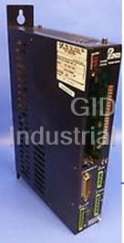
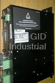
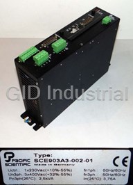

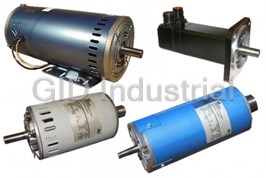
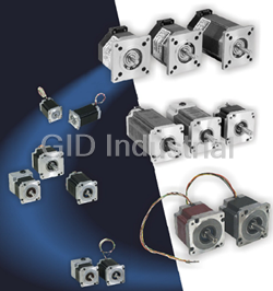


What they say about us
FANTASTIC RESOURCE
One of our top priorities is maintaining our business with precision, and we are constantly looking for affiliates that can help us achieve our goal. With the aid of GID Industrial, our obsolete product management has never been more efficient. They have been a great resource to our company, and have quickly become a go-to supplier on our list!
Bucher Emhart Glass
EXCELLENT SERVICE
With our strict fundamentals and high expectations, we were surprised when we came across GID Industrial and their competitive pricing. When we approached them with our issue, they were incredibly confident in being able to provide us with a seamless solution at the best price for us. GID Industrial quickly understood our needs and provided us with excellent service, as well as fully tested product to ensure what we received would be the right fit for our company.
Fuji
HARD TO FIND A BETTER PROVIDER
Our company provides services to aid in the manufacture of technological products, such as semiconductors and flat panel displays, and often searching for distributors of obsolete product we require can waste time and money. Finding GID Industrial proved to be a great asset to our company, with cost effective solutions and superior knowledge on all of their materials, it’d be hard to find a better provider of obsolete or hard to find products.
Applied Materials
CONSISTENTLY DELIVERS QUALITY SOLUTIONS
Over the years, the equipment used in our company becomes discontinued, but they’re still of great use to us and our customers. Once these products are no longer available through the manufacturer, finding a reliable, quick supplier is a necessity, and luckily for us, GID Industrial has provided the most trustworthy, quality solutions to our obsolete component needs.
Nidec Vamco
TERRIFIC RESOURCE
This company has been a terrific help to us (I work for Trican Well Service) in sourcing the Micron Ram Memory we needed for our Siemens computers. Great service! And great pricing! I know when the product is shipping and when it will arrive, all the way through the ordering process.
Trican Well Service
GO TO SOURCE
When I can't find an obsolete part, I first call GID and they'll come up with my parts every time. Great customer service and follow up as well. Scott emails me from time to time to touch base and see if we're having trouble finding something.....which is often with our 25 yr old equipment.
ConAgra Foods