

 Manufacturers
OPTREX DMF-50773NF-FW-ACE-AI

Description
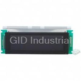
Optrex DMF-50773NF-FW-ACE-AI 5.4" FSTN 240 x 128 LCD Module
Part Number
DMF-50773NF-FW-ACE-AI
Price
Request Quote
Manufacturer
OPTREX
Lead Time
Request Quote
Category
INTEGRATED CIRCUIT
Specifications
Backlight
Cold Cathode Fluorescent Lamp (CFL) x 1
Control LSI
T6963C-0101 (Produced by TOSHIBA)
Data Transfer
8-bit parallel data transfer
Dot Pitch (WxH)
0.50 x 0.50 mm
Dot Pixels (WxH)
240 x 128 dots
Dot Size (WxH)
0.47 x 0.47 mm
Drawings
Dimensional Outline UE-36773
LCD Type
NTD-15524 (F-STN / Black & White - mode / Transmissive)
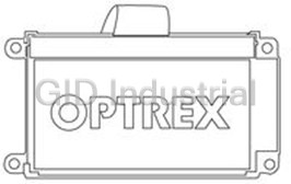
Outline Dimensions (WxHxD)
170.0 x 105.0* x 14.0 max.* mm; * Without CFL Connector
Temperature
Operating:0°C ~ 50°C; Storage:-20°C ~ 60°C
Viewing Angle
6:00
Viewing Area (WxH)
126.0 x 70.0 mm
Weight
250g max
Datasheet

Extracted Text
Approved by Production Div.
First Edition
February 5, 1997
Checked by Quality Assurance Div.
LCD Module Specification
Final Revision
Checked by Design Engineering Div.
*******
Prepared by Production Div.
Type No.
DMF–50773NF–FW
Table of Contents
1. General Specifications.................................................................2
2. Electrical Specifications...............................................................3
3. Optical Specifications..................................................................7
4. I/O Terminal..............................................................................9
5. Test........................................................................................11
6. Appearance Standards................................................................12
7. Code System of Production Lot................................................15
8. Type Number...........................................................................15
9. Applying Precautions................................................................15
10. Handling Precautions................................................................16
Revision History
Rev. Date Page Comment
DMF-50773NF-FW (AC) No.96-0315 OPTREX CORPORATION Page 1/16
OPTREX
1. General Specifications
Operating Temp. : min. 0˚C ~ max. 50˚C
Storage Temp. : min. -20˚C ~ max. 60˚C
Dot Pixels : 240 (W) ´ 128 (H) dots
Dot Size : 0.47 (W) ´ 0.47 (H) mm
Dot Pitch : 0.50 (W) ´ 0.50 (H) mm
Viewing Area : 126.0 (W) ´ 70.0 (H) mm
Outline Dimensions : 170.0 (W) ´ 105.0* (H) ´ 14.0 max.* (D) mm
* Without CFL Connector
Weight : 250g max.
LCD Type : NTD-15524
( F-STN / Black & White - mode / Transmissive )
Viewing Angle : 6:00
Control LSI : T6963C-0101 (Produced by TOSHIBA)
Data Transfer : 8-bit parallel data transfer
Backlight : Cold Cathode Fluorescent Lamp (CFL) ´ 1
Drawings : Dimensional Outline UE-36773
DMF-50773NF-FW (AC) No.96-0315 OPTREX CORPORATION Page 2/16
OPTREX
2. Electrical Specifications
2.1. Absolute Maximum Ratings
GND=0V
Parameter Symbol Conditions Min. Max. Units
Supply Voltage VDD-GND – -0.3 7.0 V
(Logic)
Supply Voltage VDD-VEE – 0 28.0 V
(LCD Drive)
Input Voltage VI – -0.3 VDD+0.3 V
2.2. DC Characteristics
Ta=25˚C, GND=0V
Parameter Symbol Conditions Min. Typ. Max. Units
Supply Voltage VDD-GND – 4.5 – 5.5 V
(Logic)
Supply Voltage VDD-VEE Shown in 3.1 V
(LCD Drive)
High Level VIH VDD=5.0V±10% VDD-2.2 – VDD V
Input Voltage
Low Level VIL VDD=5.0V±10% 0 – 0.8 V
Input Voltage
High Level VOH IOH=-0.75mA VDD-0.3 – VDD V
Output Voltage
Low Level VOL IOL=0.75mA 0 – 0.3 V
Output Voltage
IDD VDD-GND=5.0V – 9.0 14.0 mA
Supply Current
IEE VDD-VEE=18.5V – 2.9 4.5 mA
DMF-50773NF-FW (AC) No.96-0315 OPTREX CORPORATION Page 3/16
OPTREX
2.3. AC Characteristics
VDD=5.0V±10%
Parameter Symbol Min. Max. Units
C/D Setup Time tCDS 100 – ns
C/D Hold Time tCDH 10 – ns
CE, RD, WR Pulse Width tCE, tRD, tWR 80 – ns
Data Setup Time tDS 80 – ns
Data Hold Time tDH 40 – ns
Access Time tACC – 150 ns
Output Hold Time tOH 10 50 ns
C/D
t t
CDS CDH
CE
t t t
CE RD WR
RD, WR
t
t
DS DH
D0~D7
(WRITE)
t t
ACC OH
D0~D7
(READ)
DMF-50773NF-FW (AC) No.96-0315 OPTREX CORPORATION Page 4/16
OPTREX
2.4. Power Supply ON/OFF Sequence
2.4.1. ON Sequence
SIGNAL LEVEL
VDD
VDD GND
0 £ t
VDD
SIGNAL GND
£
0 t
VDD
VEE GND
VEE
2.4.2. OFF Sequence
LEVEL SIGNAL
VDD
GND VDD
£
0 t
VDD
GND SIGNAL
£
0 t
VDD
GND VEE
VEE
2.4.3. Reset Sequence
SIGNAL LEVEL
H Level
RESET L Level
s
T>2 m ³
T 0
VDD
VDD GND
³ ³ ³ ³
T 50ms T 0 T 50ms T 0
VEE VDD
VEE
Power On Reset Reset Cancellation Power Off
Please maintain the above sequence when turning on and off the power supply of the module.
If VEE is supplied to the module while internal alternate signal for LCD driving (M) is unstable
or RESET is active, DC component will be supplied to the LCD panel. This may cause damage
to the LCD module.
DMF-50773NF-FW (AC) No.96-0315 OPTREX CORPORATION Page 5/16
OPTREX
2.5. Lighting Specifications
Ta=25˚C
Parameter Symbol Conditions Min. Typ. Max. Units Notes
Lamp Voltage VL – – 350 – Vrms 1
Lamp Current IL – 4.0 5.0 6.0 mArms 2
Starting Voltage VS – 450 – – Vrms 3
2
Surface Luminance L IL = 5.0mA 100 – – cd/m 4
Average Life TAL IL = 5.0mA – 15000 – hrs 5
Note 1 : The voltage ( r.m.s. ) to maintain the electric discharge of the lamp. It is measured after lighting
for 3 minutes .
Note 2 : The current ( r.m.s. ) to flow through the lamp with the electric discharge. It is measured after
lighting for 3 minutes.
Note 3 : The voltage at starting the electric discharge when the voltage is increased gradually from 0V.
Note 4 : Surface Luminance is specified by the initial data of luminance measured at the center of display
surface after 20 minutes power on. ( All ON pattern )
the
Note 5 : CFL life is defined as the time for which the initial luminance is attenuated by 50% of??
. Av he t
luminance value ?? erage Life representes t ?? ime elapsed at the point of time when the
residual ratio becomes below 50% when plural lamps are lighted in comparison with the
niti oned
defi on of life menti above.
I C
N VS VL F
V L
CFL Testing Circuit
DMF-50773NF-FW (AC) No.96-0315 OPTREX CORPORATION Page 6/16
OPTREX
3. Optical Specifications
3.1. LCD Driving Voltage
Parameter Symbol Conditions Min. Typ. Max. Units
Recommended Ta= 0˚C – – 21.1 V
LCD Driving Voltage VDD-VEE Ta=25˚C 17.2 18.5 19.8 V
Note 1 Ta=50˚C 16.2 – – V
Note 1 : Voltage (Applied actual waveform to LCD Module) for the best contrast. The range of
minimum and maximum shows tolerance of the operating voltage. The specified contrast ratio and
response time are not guaranteed over the entire range.
3.2. Optical Characteristics
Ta=25˚C, 1/128 Duty, 1/12 Bias, VD=18.5V (Note 4), q= 0˚, f= –˚
Parameter Symbol Conditions Min. Typ. Max. Units
Contrast Ratio Note 1 CRq= 0˚, f= –˚ – 10 –
Viewing Angle Shown in 3.3
Response Rise Note 2 r – – 250 380 ms
Time Decay Note 3 d – – 230 350 ms
Note 1 : Contrast ratio is definded as follows.
CR = LON / LOFF
LON : Luminance of the ON segments
LOFF : Luminance of the OFF segments
Note 2 : The time that the luminance level reaches 90% of the saturation level from 0% when ON
signal is applied.
Note 3 : The time that the luminance level reaches 10% of the saturation level from 100% when OFF
signal is applied.
Note 4 : Definition of Driving Voltage VD
Assuming that the typical driving waveforms shown below are applied to the LCD Panel at
1/A Duty - 1/B Bias ( A : Duty Number, B : Bias Number ). Driving voltage VD is definded
as the voltage VO-P when the contrast ratio (CR=LON / LOFF) is at its maximum.
VO-P
( B-2 ) ´ VO-P / B
1 / ( fF ´ A ) 1 / fF
(ON SIGNAL)
(OFF SIGNAL)
DMF-50773NF-FW (AC) No.96-0315 OPTREX CORPORATION Page 7/16
OPTREX
t
t
3.3. Definition of Viewing Angle and Optimum Viewing Area
•Point l shows the point where contrast ratio is measured. : q= 0˚, f= –˚
•Driving condition : 1/128 Duty, 1/12 Bias, VD=18.5V, fF=70Hz
90˚
45˚
135˚
q90˚f
180˚ 10 20 30 40 50 (f= 0˚)
q
f
180˚ 0˚
225˚ 315˚
270˚
270˚
•Area shows typ. CR³2
3.4. System Block Diagram
Temperature Chamber
Rotation Table (q,f)
Photometer
#1980A WB
LCDf
Optical Fiber
q
Control Unit &
Computer
Waveform Generator
Halogen bulb
DMF-50773NF-FW (AC) No.96-0315 OPTREX CORPORATION Page 8/16
OPTREX
4. I/O Terminal
4.1. Pin Assignment
CN1
No. Symbol Level Function
1 FGND – Frame Ground
2 GND – Power Supply (0V, GND)
3 VDD – Power Supply for Logic
4 VEE – Power Supply for LCD Drive
5 WR H / L Write Signal L : Active
6 RD H / L Read Signal L : Active
7 CE H / L Chip Enable Signal L : Active
8 C/D H / L Write Mode H : Command Write L : Data Write
Read Mode H : Status Read L : Data Read
9 NC – Non-connection
10 RESET H / L Reset Signal L : Reset
11 D0 H / L Display Data
12 D1 H / L Display Data
13 D2 H / L Display Data
14 D3 H / L Display Data
15 D4 H / L Display Data
16 D5 H / L Display Data
17 D6 H / L Display Data
18 D7 H / L Display Data
19 FS H / L Font Switch H : 6 ´ 8 dots L : 8 ´ 8 dots
20 RV H / L Display Data Reverse Signal H : Reverse L : Normal
CN2
No. Symbol Level Function
1 VFL – Power Supply for CFL (HOT)
2 NC – Non-connection
3 NC – Non-connection
4 NC – Non-connection
5 VFL – Power Supply for CFL (GND)
DMF-50773NF-FW (AC) No.96-0315 OPTREX CORPORATION Page 9/16
OPTREX
4.2. Example of Power Supply
It is recommended to apply a potentiometer for the contrast adjust due to the tolerance of the
driving voltage and its temperature dependence.
VDD VDD (+Voltage)
R1
Tr
VEE
VR
MODULE
R2
VEE (-Voltage)
GND GND (0V)
R1+R2+VR=10~20 KW
Tr=2SA1202 or equivalent
4.3. Block Diagram
8
D0~D7 Row Driver 128
L C D P
T6961B ´ 2
240 ´ 128 dots
WR or equivalent
RD
3 240
Control LSI 4
CE
3
T6963C-0101 Column Driver
C/D
T6A39 ´ 3
or equivalent
RESET
FS
X-tal 12 8
X-OR
64K S-RAM
RV
VDD
GND
Bias Circuit To LSI
J
FGND
VEE
CFL Backlight
VFL
VFL
DMF-50773NF-FW (AC) No.96-0315 OPTREX CORPORATION Page 10/16
OPTREX
5. Test
No change on display and in operation under the following test condition.
No. Parameter Conditions Notes
1 High Temperature Operating 50˚C±2˚C, 96hrs (operation state)
2 Low Temperature Operating 0˚C±2˚C, 96hrs (operation state) 3
3 High Temperature Storage 60˚C±2˚C, 96hrs 4
4 Low Temperature Storage -20˚C±2˚C, 96hrs 3, 4
5 Damp Proof Test 40˚C±2˚C, 90~95%RH, 96hrs 3, 4
6 Vibration Test Total fixed amplitude : 1.5mm 5
Vibration Frequency : 10~55Hz
One cycle 60 seconds to 3 directions of X, Y, Z for
each 15 minutes
7 Shock Test To be measured after dropping from 60cm high on
the concrete surface in packing state.
Dropping method corner dropping
F A corner : once
E Edge dropping
D
G
C
B,C,D edge : once
B A
Face dropping
60cm E,F,G face : once
Concrete Surface
Note 1 : Unless otherwise specified, tests will be conducted under the following condition.
Temperature : 20±5˚C
Humidity : 65±5%
Note 2 : Unless otherwise specified, tests will be not conducted under functioning state.
Note 3 : No dew condensation to be observed.
Note 4 : The function test shall be conducted after 4 hours storage at the normal temperature and humidity
after removed from the test chamber.
Note 5 : Vibration test will be conducted to the product itself without putting it in a container.
DMF-50773NF-FW (AC) No.96-0315 OPTREX CORPORATION Page 11/16
OPTREX
6. Appearance Standards
6.1. Inspection conditions
The LCD shall be inspected under 40W white fluorescent light.
The distance between the eyes and the sample shall be more than 30cm.
All directions for inspecting the sample should be within 45˚against perpendicular line.
45˚
6.2. Definition of applicable Zones
X
X=126.0mm
Y=70.0mm
Y
A Zone
Bezel Flame
B Zone
C Zone
C Zone
A Zone : Active display area
B Zone : Area from outside of "A Zone" to validity viewing area
C Zone : Rest parts
A Zone + B Zone = Validity viewing area
DMF-50773NF-FW (AC) No.96-0315 OPTREX CORPORATION Page 12/16
OPTREX
6.3. Standards
No. Parameter Criteria
1 Black and (1) Round Shape
White Spots, Zone Acceptable Number
Foreign Substances Dimension (mm) A B C
D £0.1 * * *
0.1 < D £0.2 3 5 *
0.2 < D £0.25 2 3 *
0.25< D £0.3 0 1 *
0.3 < D 0 0 *
D = ( Long + Short ) / 2 * : Disregard
(2) Line Shape
Zone Acceptable Number
X (mm) Y (mm) A B C
– 0.03³W * * *
2.0³L 0.05³W 3 3 *
1.0³L 0.1 ³W 3 3 *
– 0.1
Frequently asked questions
What makes Elite.Parts unique?

What kind of warranty will the DMF-50773NF-FW-ACE-AI have?
Which carriers does Elite.Parts work with?
Will Elite.Parts sell to me even though I live outside the USA?
I have a preferred payment method. Will Elite.Parts accept it?
Why buy from GID?

Quality
We are industry veterans who take pride in our work

Protection
Avoid the dangers of risky trading in the gray market

Access
Our network of suppliers is ready and at your disposal

Savings
Maintain legacy systems to prevent costly downtime

Speed
Time is of the essence, and we are respectful of yours
Related Products
Size:n/a Display Format:24*2 Contrast Ratio:4:1 Luminance:n/a Backlight:no Backlight Product
Size:n/a Display Format:16*4 Contrast Ratio:9:1 Luminance:n/a Backlight:no Backlight Product
Optrex DMF-50316NF-FW-1 5.2" FSTN 240 x 64 LCD Module
Optrex DMF-50840NF-FW-ABE-AU 5.7" FSTN 320 x 240 QVGA LCD Module
Optrex DMF-50840NFL-SFW 5.7" FSTN 320 x 240 QVGA LCD Module
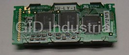
Optrex DMF-51026NYU-LY 2.5" STN 160 x 64 LCD Module
Request a Quote

The quote request has been received
Close

Facing challenges or have inquiries? Feel free to contact us!
Call Us +1-469-283-2440
What they say about us
FANTASTIC RESOURCE
One of our top priorities is maintaining our business with precision, and we are constantly looking for affiliates that can help us achieve our goal. With the aid of GID Industrial, our obsolete product management has never been more efficient. They have been a great resource to our company, and have quickly become a go-to supplier on our list!
Bucher Emhart Glass
EXCELLENT SERVICE
With our strict fundamentals and high expectations, we were surprised when we came across GID Industrial and their competitive pricing. When we approached them with our issue, they were incredibly confident in being able to provide us with a seamless solution at the best price for us. GID Industrial quickly understood our needs and provided us with excellent service, as well as fully tested product to ensure what we received would be the right fit for our company.
Fuji
HARD TO FIND A BETTER PROVIDER
Our company provides services to aid in the manufacture of technological products, such as semiconductors and flat panel displays, and often searching for distributors of obsolete product we require can waste time and money. Finding GID Industrial proved to be a great asset to our company, with cost effective solutions and superior knowledge on all of their materials, it’d be hard to find a better provider of obsolete or hard to find products.
Applied Materials
CONSISTENTLY DELIVERS QUALITY SOLUTIONS
Over the years, the equipment used in our company becomes discontinued, but they’re still of great use to us and our customers. Once these products are no longer available through the manufacturer, finding a reliable, quick supplier is a necessity, and luckily for us, GID Industrial has provided the most trustworthy, quality solutions to our obsolete component needs.
Nidec Vamco
TERRIFIC RESOURCE
This company has been a terrific help to us (I work for Trican Well Service) in sourcing the Micron Ram Memory we needed for our Siemens computers. Great service! And great pricing! I know when the product is shipping and when it will arrive, all the way through the ordering process.
Trican Well Service
GO TO SOURCE
When I can't find an obsolete part, I first call GID and they'll come up with my parts every time. Great customer service and follow up as well. Scott emails me from time to time to touch base and see if we're having trouble finding something.....which is often with our 25 yr old equipment.
ConAgra Foods