

 Manufacturers
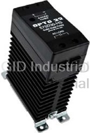
OPTO 22 480D25-HS
Description
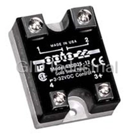
OPTO22 480D25-HS Relays-480 VAC, 25 Amp, DC Control, Transient Proof,with integrated heatsink, Solid State Relay
Part Number
480D25-HS
Price
Request Quote
Manufacturer
OPTO 22
Lead Time
Request Quote
Category
PRODUCTS - 4
Specifications
?ja* (°C/Watt)
2.2
1 cycle Surge (Amps) Peak
610
Dissipation (Nominal Watts/Amp)
1.0
I2t Rating t
8.3 (ms)
Isolation Voltage (transient 4KV)
2,500VRMS
Nominal AC Line Voltage
480
Nominal Current Rating (Amps)
25
Nominal Output Voltage Drop (RMS)
1.0 volts
Nominal Signal Input Resistance (Ohms)
1000
Off-State Leakage (mA) Maximum
10 mA
Operating Voltage Range (Volts AC)
100–530
Peak Repetitive Voltage Maximum
1000
Signal Drop-out Voltage
1 VDC
Signal Pick-up Voltage
4VDC(32V allowed)
Features
- 4,000 volts of optical isolation
- current surge before and after encapsulation
- Rugged, epoxy encapsulation construction
- Subjected to full load test and six times the rated
- Unique heat-spreader technology
Datasheet

Extracted Text
DATA SHEET Solid-State Relays Form 0859-120518 Solid-State Relays Features Rugged, epoxy encapsulation construction Opto 22 Power 4,000 volts of optical isolation Series SSR Subjected to full load test and six times the rated improvements and the same 100% testing policy established current surge before and after encapsulation over 30 years ago, Opto 22 is still recognized today for the very Unique heat-spreader technology high quality and reliability of all our solid-state relays. Guaranteed for life Description Overview Opto 22 offers a complete line of SSRs, from the rugged 120/ 240/380-volt AC Series to the small footprint MP Series, In 1974, Opto 22 introduced the first liquid epoxy-filled line of designed for mounting on printed circuit boards. All Opto 22 power solid-state relays (SSR). This innovation in SSR design SSRs feature 4,000 volts of optical isolation, and most are UL greatly improved the reliability and reduced the cost of and CSA recognized. The innovative use of room-temperature manufacturing. At that time, we also incorporated into our liquid epoxy encapsulation, coupled with Opto 22’s unique manufacturing process 100% testing under full load heat-spreader technology, are key to mass producing the conditions of every relay we produced. world’s most reliable solid state relays. By 1978, Opto 22 had gained such a reputation for reliability Every Opto 22 solid state relay is subjected to full load test and that we were recognized as the world’s leading manufacturer six times the rated current surge both before and after of solid-state relays. Through continuous manufacturing Part Numbers Part Description Part Description AC Switching AC Switching 575D15-12 575 VAC, 15 Amp, DC Control, Transient Proof 120A10 120 VAC, 10 Amp, AC Control 575D45-12 575 VAC, 45 Amp, DC Control, Transient Proof 120A25 120 VAC, 25 Amp, AC Control 575 VAC, 30 Amp, DC Control, Transient Proof, 240A10 240 VAC, 10 Amp, AC Control 575D30-HS with integrated heatsink 240A25 240 VAC, 25 Amp, AC Control 575 VAC, 45 Amp, DC Control, Transient Proof, 575Di45-12 240A45 240 VAC, 45 Amp, AC Control with LED Indicators 120D3 120 VAC, 3 Amp, DC Control MP120D2 120 VAC, 2 Amp, DC Control. 120D10 120 VAC, 10 Amp, DC Control or P120D2 P model is low profile. 120D25 120 VAC, 25 Amp, DC Control MP120D4 120 VAC, 4 Amp, DC Control. or P120D4 P model is low profile. 120D45 120 VAC, 45 Amp, DC Control MP240D2 240 VAC, 2 Amp, DC. 240D3 240 VAC, 3 Amp, DC Control or P240D2 P model is low profile. 240D10 240 VAC, 10 Amp, DC Control MP240D4 240 VAC, 4 Amp, DC. 240 VAC, 10 Amp, DC Control, with LED Indica- or P240D4 P model is low profile. 240Di10 tors MP380D4 380 VAC, 4 Amp, DC 240D25 240 VAC, 25 Amp, DC Control Z120D10 Z Model, 120 VAC, 10 Amp, DC Control 240 VAC, 25 Amp, DC Control, with LED Indica- 240Di25 Z240D10 Z Model, 240 VAC, 10 Amp, DC Control tors 240 VAC, 30 Amp, DC Control, with integrated 240D30-HS DC Switching heatsink 240D45 240 VAC, 45 Amp, DC Control DC60P or 60 VDC, 3 Amp, DC Control. DC60MP P model is low profile. 240 VAC, 45 Amp, DC Control, with LED Indica- 240Di45 tors DC200P or 200 VDC, 1 Amp, DC Control. DC200MP P model is low profile. 380D25 380 VAC, 25 Amp, DC Control DC60S-3 60 VDC, 3 Amp, DC Control 380D45 380 VAC, 45 Amp, DC Control DC60S-5 60 VDC, 5 Amp, DC Control 480D10-12 480 VAC, 10 Amp, DC Control, Transient Proof 480D15-12 480 VAC, 15 Amp, DC Control, Transient Proof 480D25-12 480 VAC, 25 Amp, DC Control, Transient Proof Accessories 480 VAC, 25 Amp, DC Control, Transient Proof, SAFETY COVER Power Series SSR safety cover 480D25-HS with integrated heatsink SSR-HS Power Series SSR heatsink 480D45-12 480 VAC, 45 Amp, DC Control, Transient Proof SSR-THERMOPAD Thermal conductive pad (pack of 10) Opto 22 • 43044 Business Park Drive • Temecula, CA 92590-3614 • www.opto22.com PAGE SALES 800-321-6786 • 951-695-3000 • FAX 951-695-3095 • sales@opto22.com • SUPPORT 800-835-6786 • 951-695-3080 • FAX 951-695-3017 • support@opto22.com 1 © 2006–2012 Opto 22. All rights reserved. Dimensions and specifications are subject to change. Brand or product names used herein are trademarks or registered trademarks of their respective companies or organizations. Solid-State Relays encapsulation. This double testing of every part before it MP Series leaves the factory means you can rely on Opto 22 solid state The MP Series packaging is designed with a minimum relays. All Opto 22 SSRs are guaranteed for life. footprint to allow maximum relay density on the printed Accessories for the Power-Series SSRs include a safety cover, circuit board. heatsink, and a matching thermal conductive pad. See page 3. P Series The P Series power relays provide low-profile [0.5 in. Power Series SSRs (12.7 mm)] center mounting on printed circuit boards. Opto 22 provides a full range of Power Series relays with a wide HS Series SSRs variety of voltage (120–575 volts) and current options (3–45 amps). The HS Series features an integrated All Power Series relays feature 4,000 heatsink, which makes them so cool. volts of optical isolation and have a These relays have less thermal high PRV rating. Some Power Series resistance inside, so heat dissipates relays include built-in LEDs to more easily than in a standard SSR indicate operation. mounted to the same heatsink. With See page 4. the heatsink built-in, you don't have to select one from a catalog, and DC Series installation is much easier. See The DC Series delivers isolated DC control to large OEM page 13. customers worldwide. All DC control SSRs are LS TTL compatible. Specifications AC Series (all Power Series models) The AC Series offers the ultimate in solid state reliability. All AC • 4,000 V optical isolation, input to output Power Series relays feature a built-in snubber and zero voltage • Zero voltage turn-on turn on. Transient-proof models offer self protection for noisy • Turn-on time: 0.5 cycle maximum electrical environments. • Turn-off time: 0.5 cycle maximum • Operating temperature: –40 °C to 100 °C Z Series SSRs • Operating frequency: 25 to 65 Hz The Z Series employs a unique heat (operates at 400 Hz with six times off-state leakage) transfer system that makes it • Coupling capacitance, input to output: 8 pF maximum possible for Opto 22 to deliver a • Hermetically sealed low-cost, 10-amp, solid state relay • DV/DT Off-state: 200 volts per microsecond in an all-plastic case. The push-on, tool-free quick-connect terminals • DV/DT commutating: snubbed for rated current at make the Z Series ideal for high- 0.5 power factor volume OEM applications. • UL recognized Operating temperature: –40 °C to • CSA certified 100 °C. See page 7. • CE component • Torque specs for screws: Printed Circuit Series SSRs Control terminals, 10 in-lb (1.13 N-m) Field terminals, 35 in-lb (3.95 N-m) Opto 22’s Printed Circuit Series allows OEMs to easily deploy solid state relays on printed circuit boards. Two unique packages are available, both of which will switch loads up to four amps. Operating temperature: –40 °C to 100 °C. See page 9. Opto 22 • 43044 Business Park Drive • Temecula, CA 92590-3614 • www.opto22.com PAGE SALES 800-321-6786 • 951-695-3000 • FAX 951-695-3095 • sales@opto22.com • SUPPORT 800-835-6786 • 951-695-3080 • FAX 951-695-3017 • support@opto22.com 2 © 2006–2012 Opto 22. All rights reserved. Dimensions and specifications are subject to change. Brand or product names used herein are trademarks or registered trademarks of their respective companies or organizations. DATA SHEET Solid-State Relays Form 0859-120518 DATA SHEET Solid-State Relays Form 0859-120518 Solid-State Relays 25 Amp Relay on SSR-HS Heatsink Derating Power Series SSR Accessories 30 Safety Cover 25 A plastic safety cover (Opto 22 part number SAFETY COVER) is 20 available for use with Opto 22 Power Series SSRs. The safety V cover reduces the chance of accidental contact with relay 15 H terminals, while providing access holes for test 10 instrumentation. 5 20 30 40 50 60 70 80 90 100 Ambient Temperature (°C) V: Heatsink mounted to a vertical surface H: Heatsink mounted to a horizontal surface. Heatsink Assembly Before attaching the SSR, remove the protective film from both sides of the thermal pad, then place the pad on the heatsink making sure to align the holes. Secure the SSR to the An optional plastic safety cover can be installed on a Power Series SSR. heatsink with the two 8-32 x 3/8˝ panhead Phillips screws included in the kit. Use 20 in-lb (2.26 N-m) of torque. SSR-HS Heatsink Custom designed for the Power Series SSRs, the SSR-HS Screws heatsink provides excellent heat dissipation when mounted to the SSR with a matching thermal conductive pad, which is used in place of silicon grease. One thermal pad is included Power Series SSR with the heatsink. Additional pads may be purchased in packs (not included) of 10 (part number SSR-THERMOPAD). Thermal conductive pad Thermal Ratings The thermal ratings shown in the following graphs were Heatsink obtained with an SSR attached to a heatsink using a thermal conductive pad. 45 Amp Relay on SSR-HS Heatsink Derating 30 25 V 20 H 15 NOTE: To take advantage of the 10 cooling effect of natural air flow, mount the SSR/heatsink assembly to 5 a vertical surface with the Opto 22 logo right side up as shown here. 20 30 40 50 60 70 80 90 100 Ambient Temperature (°C) V: Heatsink mounted to a vertical surface H: Heatsink mounted to a horizontal surface. Opto 22 • 43044 Business Park Drive • Temecula, CA 92590-3614 • www.opto22.com PAGE SALES 800-321-6786 • 951-695-3000 • FAX 951-695-3095 • sales@opto22.com • SUPPORT 800-835-6786 • 951-695-3080 • FAX 951-695-3017 • support@opto22.com 3 © 2006–2012 Opto 22. All rights reserved. Dimensions and specifications are subject to change. Brand or product names used herein are trademarks or registered trademarks of their respective companies or organizations. RMS Amperes RMS Amperes Solid-State Relays AC Power Series Specifications Opto 22 provides a full range of Power Series relays with a wide variety of voltage (120–575) and current options (3–45 amps). All Power Series relays feature 4,000 volts of optical isolation and have a high PRV rating. Operating temperature is –40 °C to 100 °C. Connection Diagram 120/240/380 Volt NOTE: Model numbers ending in -17 are replacement parts only. Their specifications are identical to the same model number without the -17. For example, 240D10-17 is identical to 240D10. 2 Model Nominal Nominal 1 cycle Nominal Signal Signal Peak Maximum Off-State Operating Isolation Dissipation θjc* I t Number AC Line Current Surge Signal Input Pick-up Drop- Repetitive Output Leakage Voltage Voltage (Watts/ Rating (°C/Watt) Voltage Rating (Amps) Resistance Voltage out Voltage Voltage (mA) Range Amp) t=8.3 (Amps) Peak (Ohms) Voltage Maximum Drop Maximum** (Volts AC) (ms) 120D3 120 3 85 1000 3VDC 1 VDC 600 1.6 volts 2.5mA 12–140 30 4,000V 11 1.7 RMS (32V allowed) rent Control varies with control voltage. See “Control 120D10 120 10 110 1000 3VDC 1 VDC 600 1.6 volts 7 mA 12–140 50 4,000V 1.3 1.6 RMS ent Calculation” on page 17 for information. (32V allowed) 120D25 120 25 250 1000 3VDC 1 VDC 600 1.6 volts 7 mA 12–140 250 4,000V 1.2 1.3 RMS (32V allowed) 120D45 120 45 650 1000 3VDC 1 VDC 600 1.6 volts 7 mA 12–140 1750 4,000V 0.67 0.9 RMS (32V allowed) 240D3 240 3 85 1000 3VDC 1 VDC 600 1.6 volts 5 mA 24–280 30 4,000V 11 1.7 RMS (32V allowed) 240D10 240 10 110 1000 3VDC 1 VDC 600 1.6 volts 14 mA 24–280 50 4,000V 1.3 1.6 RMS (32V allowed) 240Di10 240 10 110 730 3VDC 1 VDC 600 1.6 volts 14 mA 24–280 50 4,000V 1.3 1.6 RMS (32V allowed) 240D25 240 25 250 1000 3VDC 1 VDC 600 1.6 volts 14 mA 24–280 250 4,000V 1.2 1.3 RMS (32V allowed) 240Di25 240 25 250 730 3VDC 1 VDC 600 1.6 volts 14 mA 12–280 250 4,000V 1.2 1.3 RMS (32V allowed) 240D45 240 45 650 1000 3VDC 1 VDC 600 1.6 volts 14 mA 24–280 1750 4,000V 0.67 0.9 RMS (32V allowed) 240Di45 240 45 650 730 3VDC 1 VDC 600 1.6 volts 14 mA 24–280 1750 4,000V 0.67 0.9 RMS (32V allowed) 380D25 380 25 250 1000 3VDC 1 VDC 800 1.6 volts 12 mA 24–420 250 4,000V 1.2 1.3 RMS (32V allowed) 380D45 380 45 650 1000 3VDC 1 VDC 800 1.6 volts 12 mA 24–420 1750 4,000V 0.67 0.9 RMS (32V allowed) 120A10 120 10 110 33K 85VAC 10 VAC 600 1.6 volts 7 mA 12–140 50 4,000V 1.3 1.6 RMS (280V allowed) 120A25 120 25 250 33K 85VAC 10 VAC 600 1.6 volts 7 mA 12–140 250 4,000V 1.2 1.3 RMS (280V allowed) 240A10 240 10 110 33K 85VAC 10 VAC 600 1.6 volts 14 mA 24–280 50 4,000V 1.3 1.6 RMS (280V allowed) 240A25 240 25 250 33K 85VAC 10 VAC 600 1.6 volts 14 mA 24–280 250 4,000V 1.2 1.3 RMS (280V allowed) 240A45 240 45 650 33K 85VAC 10 VAC 600 1.6 volts 14 mA 24–280 1750 4,000V 0.67 0.9 RMS (280V allowed) Note: θjc* = Thermal resistance from internal junction to base. Maximum internal junction temperature is 110 °C. ** Operating Frequency: 25 to 65 Hz (operates at 400 Hz with 6 times the offstate leakage) Connection Diagram, DC Power Series *Control Current varies with control voltage. See “Control Current Calculation” on page 17 for information. Opto 22 • 43044 Business Park Drive • Temecula, CA 92590-3614 • www.opto22.com PAGE SALES 800-321-6786 • 951-695-3000 • FAX 951-695-3095 • sales@opto22.com • SUPPORT 800-835-6786 • 951-695-3080 • FAX 951-695-3017 • support@opto22.com 4 © 2006–2012 Opto 22. All rights reserved. Dimensions and specifications are subject to change. Brand or product names used herein are trademarks or registered trademarks of their respective companies or organizations. DATA SHEET Solid-State Relays Form 0859-120518 DATA SHEET Solid-State Relays Form 0859-120518 Solid-State Relays Thermal Ratings 120/240/380 Volt (cont.) Surge Current Data 3-Amp 10-Amp 25-Amp 45-Amp Time Time* Peak Peak Peak Peak (Seconds) (Cycles) Amps Amps Amps Amps 0.017 1 85 110 250 650 0.050 3 66 85 175 420 0.100 6 53 70 140 320 0.200 12 45 60 112 245 0.500 30 37 50 80 175 1 60 31 40 67 134 2 120 28 33 53 119 3 180 27 32 49 98 4 240 26 31 47 95 5 300 25 30 45 91 10 600 24 28 42 84 Note: *60 HZ. Connection Diagram, AC Power Series Mounted on a heat sink with 2 °C/watt rating Mounted on a heat sink with 1 °C/watt rating Dimensional Drawings Side view: Part numbers DC60S3, 120D3, and 240D3 only 3-32VDC Control Side view: All other + part numbers Opto 22 • 43044 Business Park Drive • Temecula, CA 92590-3614 • www.opto22.com PAGE SALES 800-321-6786 • 951-695-3000 • FAX 951-695-3095 • sales@opto22.com • SUPPORT 800-835-6786 • 951-695-3080 • FAX 951-695-3017 • support@opto22.com 5 © 2006–2012 Opto 22. All rights reserved. Dimensions and specifications are subject to change. Brand or product names used herein are trademarks or registered trademarks of their respective companies or organizations. Solid-State Relays 480/575 Volt Model Nominal Nominal 1 cycle Nominal Signal Signal Peak Maximum Off-State Operating 2 Isolation Dissipation I t θjc* Number AC Line Current Surge Signal Input Pick-up Drop- Repetitive Output Leakage Voltage Voltage (Watts/Amp) Rating (°C/Watt) Voltage Rating (Amps) Resistance Voltage out Voltage Voltage (mA) Range t=8.3 (Amps) Peak (Ohms) Voltage Maximum Drop Maximum** (Volts AC) (ms) 480D10-12 480 10 110 1000 3VDC 1 VDC 1200 3.2 volts 11 mA 100–530 50 4,000V 1.2 2.5 RMS (32V allowed) 480D15-12 480 15 150 1000 3VDC 1 VDC 1200 3.2 volts 11 mA 100–530 50 4,000V 1.2 2.5 RMS (32V allowed) 480D25-12 480 25 250 1000 3VDC 1 VDC 1000 1.6 volts 11 mA 100–530 250 4,000V 1.3 1.3 RMS (32V allowed) 480D45-12 480 45 650 1000 3VDC 1 VDC 1000 1.6 volts 11 mA 100–530 1750 4,000V 0.67 0.9 RMS (32V allowed) 575D15-12 575 15 150 1000 3VDC 1 VDC 1200 3.2 volts 15 mA 100–600 90 4,000V 1.2 2.5 RMS (32V allowed) 575D45-12 575 45 650 1000 3VDC 1 VDC 1000 1.6 volts 15 mA 100–600 1750 4,000V 0.67 0.9 RMS (32V allowed) 575Di45-12 575 45 650 730 3VDC 1 VDC 1000 1.6 volts 15 mA 100–600 1750 4,000V 0.67 0.9 RMS (32V allowed) Note: θjc* = Thermal resistance from internal junction to base. Maximum internal junction temperature is 110 °C. ** Operating Frequency: 25 to 65 Hz (operates at 400 Hz with 6 times the offstate leakage) Surge Current Data Thermal Ratings 10-Amp 15-Amp 25-Amp 45-Amp Time Time*** Peak Peak Peak Peak Second (Cycles) Amps Amps Amps Amps 0.017 1 110 150 250 650 0.050 3 85 140 175 420 0.100 6 70 110 140 320 0.200 12 60 90 112 245 0.500 30 50 70 80 175 1 60 40 55 67 134 Mounted on a heat sink with 2 120 33 49 53 119 2 °C/watt rating 3 180 32 47 49 98 Mounted on a heat sink with 4 240 31 43 47 95 1 °C/watt rating 5 300 30 40 45 91 10 600 28 35 42 84 Note: ***60 HZ Opto 22 • 43044 Business Park Drive • Temecula, CA 92590-3614 • www.opto22.com PAGE SALES 800-321-6786 • 951-695-3000 • FAX 951-695-3095 • sales@opto22.com • SUPPORT 800-835-6786 • 951-695-3080 • FAX 951-695-3017 • support@opto22.com 6 © 2006–2012 Opto 22. All rights reserved. Dimensions and specifications are subject to change. Brand or product names used herein are trademarks or registered trademarks of their respective companies or organizations. DATA SHEET Solid-State Relays Form 0859-120518 DATA SHEET Solid-State Relays Form 0859-120518 Solid-State Relays 480/575 Volt (cont) Dimensional Drawings Side view: Part numbers DC60S3, 120D3, and 240D3 only 3-32VDC Control Side view: All other + part numbers Z Series Specifications AC Power: 120/240 Volt The Z Series employs a unique heat transfer system that makes it possible for Opto 22 to deliver a low-cost, 10-amp, solid-state relay in an all-plastic case. The push-on tool-free quick-connect terminals make the Z Series ideal for high-volume OEM applications. Operating temperature is –40 °C to 100 °C. NOTE: Part number Z240D10-17 is a replacement part only. Its specifications are identical to Z240D10. Z120D10 Z240D10 Nominal AC Line Voltage Nominal 120 240 Current Rating (Amps) 10 10 1 cycle Surge (Amps) Peak 110 110 Nominal Signal Input Resistance (Ohms) 1000 1000 3VDC (32V 3VDC (32V Signal Pick-up Voltage allowed) allowed) Signal Drop-out Voltage 1 VDC 1 VDC Peak Repetitive Voltage Maximum 600 600 Maximum Output Voltage Drop 1.6 volts 1.6 volts Off-State Leakage (mA) Maximum** 6 mA 12 mA Operating Voltage Range (Volts AC) 12–140 24–280 2 50 50 I t Rating t=8.3 (ms) 4,000 V 4,000 V Isolation Voltage RMS RMS θjc* (°C/Watt) Dissipation (Watts/Amp) 4 4 Notes: θjc* = Thermal resistance from internal junction to base. Maximum internal junc- tion temperature is 110°C. ** Operating Frequency: 25–65 Hz (operates at 400 Hz with 6 times the offstate leakage) Opto 22 • 43044 Business Park Drive • Temecula, CA 92590-3614 • www.opto22.com PAGE SALES 800-321-6786 • 951-695-3000 • FAX 951-695-3095 • sales@opto22.com • SUPPORT 800-835-6786 • 951-695-3080 • FAX 951-695-3017 • support@opto22.com 7 © 2006–2012 Opto 22. All rights reserved. Dimensions and specifications are subject to change. Brand or product names used herein are trademarks or registered trademarks of their respective companies or organizations. Solid-State Relays AC Power: 120/240 Volt (cont.) Current vs. Ambient Ratings Surge Current Data Mounted on a heat sink with 2 °C/watt rating Connection Diagram *Control Current varies with control voltage. See “Control Current Calculation” on page 17 for information. Dimensional Drawings Opto 22 • 43044 Business Park Drive • Temecula, CA 92590-3614 • www.opto22.com PAGE SALES 800-321-6786 • 951-695-3000 • FAX 951-695-3095 • sales@opto22.com • SUPPORT 800-835-6786 • 951-695-3080 • FAX 951-695-3017 • support@opto22.com 8 © 2006–2012 Opto 22. All rights reserved. Dimensions and specifications are subject to change. Brand or product names used herein are trademarks or registered trademarks of their respective companies or organizations. DATA SHEET Solid-State Relays Form 0859-120518 DATA SHEET Solid-State Relays Form 0859-120518 Solid-State Relays Printed Circuit Series Specifications AC Power: MP and P Series The MP Series packaging is designed with a minimum footprint to allow maximum relay density on the printed circuit board. The P Series power relays provide low-profile for 0.5-inch (12.7 mm) center mounting on printed circuit boards. Operating temperature: –40 °C to 100 °C. MP120D2 MP120D4 MP240D2 MP240D4 MP380D4 or P120D2 or P120D4 or P240D2 or P240D4 Nominal AC Line Voltage 120 120 240 240 380 Nominal Current Rating 2 4 244 Amps 1 cycle Surge (Amps) 20 85 20 85 85 Peak Nominal Signal Input 1000 1000 1000 1000 1000 Resistance (Ohms) 3VDC*** 3VDC*** 3VDC*** 3VDC*** 3VDC*** Signal Pick-up Voltage (24V allowed) (24V allowed) (24V allowed) (24V allowed) (24V allowed) Signal Drop-out Voltage 1 VDC 1 VDC 1 VDC 1 VDC 1 VDC Peak Repetitive Voltage 600 600 600 600 800 Maximum Maximum Output Volt- 1.6 volts 1.6 volts 1.6 volts 1.6 volts 1.6 volts age Drop Off-State Leakage mA 5 mA 5 mA 5 mA 5 mA 5 mA Maximum** Operating Voltage 12–140 12–140 24–280 24–280 24–420 Range (Volts AC) 2 2 30 2 30 30 I t Rating t=8.3 (ms) Isolation Voltage 4,000 V 4,000 V 4,000 V 4,000 V 4,000 V RMS RMS RMS RMS RMS θjc* °C/Watt 20 6.5 20 6.5 6.5 Dissipation Watts/Amp 1.2 1.2 1.2 1.2 1.2 1 FLA at 120 VAC 2.5 FLA at 240 VAC 1 FLA at 120 VAC 2.5 FLA at 240 VAC 2.5 FLA at 380 VAC Rating (Motor Load) 6 LRA at 120 VAC 6 LRA at 240 VAC 15 LRA at 120 VAC 15 LRA at 240 VAC 15 LRA at 380 VAC Notes: θjc* = Thermal resistance from internal junction to base. Maximum internal junction temperature is 110 °C. ** Operating Frequency: 25 to 65 Hz (operates at 400 Hz with 6 times the offstate leakage) *** = P Series 32 volts maximum. Connnection Diagram NOTE: Part numbers ending in -17 are replacement parts only. Their specifications are identical to the same part number without the -17. For example, P240D4-17 is identical to P240D4. *Control Current varies with control voltage. See “Control Current Calculation” on page 17 for information. Opto 22 • 43044 Business Park Drive • Temecula, CA 92590-3614 • www.opto22.com PAGE SALES 800-321-6786 • 951-695-3000 • FAX 951-695-3095 • sales@opto22.com • SUPPORT 800-835-6786 • 951-695-3080 • FAX 951-695-3017 • support@opto22.com 9 © 2006–2012 Opto 22. All rights reserved. Dimensions and specifications are subject to change. Brand or product names used herein are trademarks or registered trademarks of their respective companies or organizations. Solid-State Relays AC Power: MP and P Series (cont.) Surge Current Data Dimensional Drawings Time Time* 2-Amp 4-Amp Second (Cycles) Peak Amps Peak Amps 0.017 1 20 85 0.050 3 18 66 0.100 6 15 53 0.200 12 11 45 0.500 30 9 37 160 8.5 31 2120 8 28 3 180 7.5 27 4240 7 26 5 300 6.5 25 10 600 6 24 Note: *60 Hz Thermal Ratings Mounted on a heat sink with 2 °C/watt rating Opto 22 • 43044 Business Park Drive • Temecula, CA 92590-3614 • www.opto22.com PAGE SALES 800-321-6786 • 951-695-3000 • FAX 951-695-3095 • sales@opto22.com • SUPPORT 800-835-6786 • 951-695-3080 • FAX 951-695-3017 • support@opto22.com 10 © 2006–2012 Opto 22. All rights reserved. Dimensions and specifications are subject to change. Brand or product names used herein are trademarks or registered trademarks of their respective companies or organizations. DATA SHEET Solid-State Relays Form 0859-120518 DATA SHEET Solid-State Relays Form 0859-120518 Solid-State Relays DC Switching Series Specifications Thermal Ratings DC60P DC200P or DC60S-3 DC60S-5 or DC60MP DC200MP Operating Voltage 5–60 VDC 5–200 VDC 5–60 VDC 5–60 VDC Range 1.5 volts 1.5 volts 1.5 volts 1.5 volts Forward Voltage Drop at 3 amps at 1 amp at 3 amps at 5 amps Nominal Currrent Rating 3 amps 1 amp 3 amps 5 amps Off-State Blocking 60 VDC 250 VDC 60 VDC 60 VDC 3 VDC 3 VDC 3 VDC 3 VDC Signal Pickup Voltage 32 Volts* 32 Volts* 32 Volts 32 Volts allowed allowed allowed allowed Signal Dropout Voltage 1 VDC 1 VDC 1 VDC 1 VDC Signal Input 1,000 ohms 1,000 ohms 1,000 ohms 1,000 ohms Impedeance 1 Second Surge 5 amps 2 amps 5 amps 10 amps –40 °C to –40 °C to –40 °C to –40 °C to Operating Temp. Range 100 °C 100 °C 100 °C 100 °C 4,000 V 4,000 V 4,000 V 4,000 V Isolation Voltage RMS RMS RMS RMS 1 mA 1 mA 1 mA 1 mA Off-State Leakage maximum maximum maximum maximum Power Power Package Type P/MP series P/MP series series series Turn-on Time 100 usec 100 usec 100 usec 100 usec Turn-off Time 750 usec 750 usec 750 usec 750 usec Note: *MP series maximum allowed control signal at 24 VDC. For more information, see form #859, the Solid-State Relays Data Sheet. NOTE: When controlling an inductive load, like a solenoid or coil, a commutating diode Mounted on a heat sink with must be used. Install the commutating diode across the terminals of the load (not the 2 °C/watt rating SSR terminals). This will protect the SSR from damage caused by voltage spikes when turning off the load. Model DC60MP Basic Schematic *Control Current varies with control voltage. See “Control Current Calculation” on page 17 for information. Opto 22 • 43044 Business Park Drive • Temecula, CA 92590-3614 • www.opto22.com PAGE SALES 800-321-6786 • 951-695-3000 • FAX 951-695-3095 • sales@opto22.com • SUPPORT 800-835-6786 • 951-695-3080 • FAX 951-695-3017 • support@opto22.com 11 © 2006–2012 Opto 22. All rights reserved. Dimensions and specifications are subject to change. Brand or product names used herein are trademarks or registered trademarks of their respective companies or organizations. Solid-State Relays Dimensional Drawings Side view: Part numbers DC60S3, 120D3, and 240D3 only (+) (+) Side view: All other part numbers (+) (+) (+) (+) Opto 22 • 43044 Business Park Drive • Temecula, CA 92590-3614 • www.opto22.com PAGE SALES 800-321-6786 • 951-695-3000 • FAX 951-695-3095 • sales@opto22.com • SUPPORT 800-835-6786 • 951-695-3080 • FAX 951-695-3017 • support@opto22.com 12 © 2006–2012 Opto 22. All rights reserved. Dimensions and specifications are subject to change. Brand or product names used herein are trademarks or registered trademarks of their respective companies or organizations. DATA SHEET Solid-State Relays Form 0859-120518 DATA SHEET Solid-State Relays Form 0859-120518 Solid-State Relays HS Series Specifications The HS Series features an integrated heatsink, which makes them so cool. Because there is less thermal resistance internal to the unit than in a standard SSR mounted to the same heat sink, heat dissipates more easily. The built-in heatsink means you don't have to select a heatsink, and installation is much easier. Each HS-series SSR has built-in hardware for screw mounting and a built- in DIN-rail adapter clip for mounting to a 35mm DIN rail. Model Number 240D30-HS 480D25-HS 575D30-HS Nominal AC Line Voltage 240 480 575 Operating Voltage Range (Volts AC) 24–280 100–530 100–600 Peak Repetitive Voltage Maximum 600 1000 1200 Off-State Leakage (mA) Maximum** 5 mA 10 mA 12 mA Nominal Output Voltage Drop (RMS) 1.0 volts 1.0 volts 1.0 volts Nominal Current Rating (Amps) 30 25 30 1 cycle Surge (Amps) Peak 610 610 610 2 1550 1550 1550 I t Rating t=8.3 (ms) Isolation Voltage (transient 4KV) 2,500V 2,500V 2,500V RMS RMS RMS Dissipation (Nominal Watts/Amp) 1.0 1.0 1.0 4VDC 4VDC 4VDC Signal Pick-up Voltage (32V allowed) (32V allowed) (32V allowed) Signal Drop-out Voltage 1 VDC 1 VDC 1 VDC Nominal Signal Input Resistance (Ohms) 730 1000 1000 θja* (°C/Watt) 2.2 2.2 2.2 Note: θja* = Thermal resistance from internal junction to ambient. Maximum internal junction temperature is 110 °C. ** Operating Frequency: 25 to 65 Hz (operates at 400 Hz with 6 times the offstate leakage) Surge Current Data, Peak Amps Time 60HZ 50HZ Second 0.0167 610 580 0.05 394 375 0.1 300 386 0.2 230 219 0.5 164 156 1 126 120 2 112 106 392 87 489 85 585 81 10 79 75 Opto 22 • 43044 Business Park Drive • Temecula, CA 92590-3614 • www.opto22.com PAGE SALES 800-321-6786 • 951-695-3000 • FAX 951-695-3095 • sales@opto22.com • SUPPORT 800-835-6786 • 951-695-3080 • FAX 951-695-3017 • support@opto22.com 13 © 2006–2012 Opto 22. All rights reserved. Dimensions and specifications are subject to change. Brand or product names used herein are trademarks or registered trademarks of their respective companies or organizations. Solid-State Relays HS-series (cont.) Thermal Ratings 30 30 25 25 A A 20 20 B B 15 15 10 10 5 5 20 30 40 50 60 70 80 90 100 20 30 40 50 60 70 80 90 100 Ambient Temperature (°C) Ambient Temperature (°C) A: Single relay or with 0.75” spacing between relays. Derate above 40 °C; subtract 0.5 amp/°C. B: Three relays side by side with 0.25” spacing. All relays with the same load. Derate above 40 °C; subtract 0.4 amp/°C. NOTE: This data is for SSRs mounted to a horizontal surface. To take advantage of the cooling effect of natural air flow, we recommend mounting HS-series SSRs to a vertical surface with the Opto 22 logo right side up as shown here. Dimensional 3.90” (99.11mm) 3.50” (88.90mm) 0.20” (5.08mm) 1.25” (31.75mm) 0.25” (6.35mm) 1.75” 3.21” (81.55mm) (44.45mm) 4.81” (122.17mm) Opto 22 • 43044 Business Park Drive • Temecula, CA 92590-3614 • www.opto22.com PAGE SALES 800-321-6786 • 951-695-3000 • FAX 951-695-3095 • sales@opto22.com • SUPPORT 800-835-6786 • 951-695-3080 • FAX 951-695-3017 • support@opto22.com 14 © 2006–2012 Opto 22. All rights reserved. Dimensions and specifications are subject to change. Brand or product names used herein are trademarks or registered trademarks of their respective companies or organizations. DATA SHEET Solid-State Relays Form 0859-120518 30 Amp Models RMS Amperes 25 Amp Models RMS Amperes DATA SHEET Solid-State Relays Form 0859-120518 Solid-State Relays Applications: Tips Heat Sink Calculation Like all semiconductor devices, SSR current ratings must be based on maximum internal junction temperature. All Opto 22 SSRs operate conservatively at maximum internal junction temperatures of 110 °C. Use the equation below to calculate the maximum allowable heat sink thermal resistance for your application. It is good engineering practice to provide a margin for error instead of running the application right at the limits. If your application is near the thermal limit, it can be helpful to add a fan to move air across the heat sink. IMPORTANT: Thermally conductive grease must be used between the relay base and the heat sink. Sample Calculation 1 120-volt, 20-amp load; 50 °C ambient air temperature Model: 120D25 SSR. See the last two columns of the table on page 4 for thermal resistance and dissipation values for the 120D25. Also, see the note at the bottom of the table. Dissipation: 1.3 watts/amp Thermal resistance: 1.2 °C/watt Maximum junction temperature: 110 °C The calculation would be as follows: This calculation indicates that you should select a heat sink with a thermal resistance of less than 1.1 °C/watt. Opto 22 • 43044 Business Park Drive • Temecula, CA 92590-3614 • www.opto22.com PAGE SALES 800-321-6786 • 951-695-3000 • FAX 951-695-3095 • sales@opto22.com • SUPPORT 800-835-6786 • 951-695-3080 • FAX 951-695-3017 • support@opto22.com 15 © 2006–2012 Opto 22. All rights reserved. Dimensions and specifications are subject to change. Brand or product names used herein are trademarks or registered trademarks of their respective companies or organizations. Solid-State Relays Sample Calculation 2 240-volt,18-amp load, 25 °C ambient air temperature Model: 240D45 See the last two columns of the table on page 4 for thermal resistance and dissipation values for the 240D45. Also, see the note at the bottom of the table. Dissipation: 0.9 watts/amp Thermal resistance: 0.67 °C/watt Maximum junction temperature: 110 °C The calculation would be as follows: This calculation indicates that you should select a heat sink with a thermal resistance of less than 4.6 °C/watt. Duty Cycle Calculation When solid-state relays are operated in an on/off mode, it may be advantageous to calculate the RMS value of the current through the SSR for heat sinking or determining the proper current rating of the SSR for the given application. I = RMS value of load or SSR RMS 2 T = Time current is on I = (I ) x T 1 RMS ON 1 T = Time current is off 2 T + T I = RMS value of load current during on period 1 2 ON Opto 22 • 43044 Business Park Drive • Temecula, CA 92590-3614 • www.opto22.com PAGE SALES 800-321-6786 • 951-695-3000 • FAX 951-695-3095 • sales@opto22.com • SUPPORT 800-835-6786 • 951-695-3080 • FAX 951-695-3017 • support@opto22.com 16 © 2006–2012 Opto 22. All rights reserved. Dimensions and specifications are subject to change. Brand or product names used herein are trademarks or registered trademarks of their respective companies or organizations. DATA SHEET Solid-State Relays Form 0859-120518 DATA SHEET Solid-State Relays Form 0859-120518 Solid-State Relays Transformer Loads Control Current Calculation Careful consideration should be given to the selection of the All Opto 22 DC-controlled SSRs have a control circuit proper SSR for driving a given transformer. Transformers are consisting of 1000 ohms in series with an LED. The LED will driven from positive saturation of the iron core to negative drop 1 volt, so the voltage across the internal resistor will be 1 saturation of the core each half cycle of the alternating volt less than the control voltage. voltage. Large inrush currents can occur during the first half The control current (I ) can be calculated from the control C cycle of line voltage if a zero-voltage SSR happens to turn on voltage (V ) as follows: C during the positive half cycle of voltage when the core is already in positive saturation. Inrush currents greater than 10 I = (V - 1)/1000 C C times rated transformer current can easily occur. The following Examples: table provides a guide for selecting the proper SSR for a given transformer rating. 3 VDC control voltage: I = (3 - 1)/1000 = 0.002 A (2 mA) C 32 VDC control voltage: I = (32 - 1)/1000 = 0.031 A (31 mA) C For control voltages above 32 VDC, an external resistor can be added in series with the SSR to limit the control current. Also, if the device driving the control current to the SSR is limited, you can limit the control current by using an external resistor (R ). e I = (V - 1)/ (R + 1000) e C C R = [(V - 1)/(I )] -1000 e C C To limit the control current to 2 mA, this simplifies to: R = 500 (V - 3) e C Solenoid Valve and Contactor Loads All Opto 22 SSRs are designed to drive inductive loads such as solenoid valves and electromechanical contactors. The built-in snubber in each SSR assures proper operation into inductive loads. The following table is a guide in selecting an SSR to drive a solenoid or contactor. 120-Volt Coils SSR CURRENT SOLENOID CONTACTOR RATING 2-Amp 1-Amp NEMA Size 4 4-Amp 3-Amp NEMA Size 7 240-Volt Coils SSR CURRENT SOLENOID CONTACTOR RATING 2-Amp 1-Amp NEMA Size 7 4-Amp 3-Amp NEMA Size 7 Opto 22 • 43044 Business Park Drive • Temecula, CA 92590-3614 • www.opto22.com PAGE SALES 800-321-6786 • 951-695-3000 • FAX 951-695-3095 • sales@opto22.com • SUPPORT 800-835-6786 • 951-695-3080 • FAX 951-695-3017 • support@opto22.com 17 © 2006–2012 Opto 22. All rights reserved. Dimensions and specifications are subject to change. Brand or product names used herein are trademarks or registered trademarks of their respective companies or organizations. Solid-State Relays Opto 22 SSRs for controlling single-phase motors are shown in Solid-State Relays in Series the following tables: In applications requiring higher voltage, two Opto 22 SSRs may be operated in series for double the voltage rating. The built-in snubber in each SSR assures proper voltage sharing of 120-Volt Single-Phase the two SSRs in series. In the following diagram, two 240-volt, Non-Reversing Motors 45-amp SSRs are connected in series for operation on a 480- SSR Model MOTOR RATING volt line. The control is shown with a parallel hook-up but it P or MP120D2 1 Amp should be noted that a serial connection can also be Z120D10 1/4 HP implemented. 120D3 1-1/2 Amp P or MP120D4 1-1/2 Amp 120D10 or 120A10 1/4 HP 120D25 or 120A25 1/3 HP 120D45 3/4 HP 240-Volt Single Phase Non-Reversing Motors SSR Model MOTOR RATING P or MP240D2 1 Amp Lamp Loads Z240D10 1/4 HP Since all Opto 22 SSRs are zero-voltage switching, they are ideal 240D3 1-1/2 Amp for driving incandescent lamps, because the initial inrush P or MP240D4 1-1/2 Amp current into a cold filament is reduced. The life of the lamp is 240D10 or 240A10 1/3 HP increased when switched by a zero-voltage turn-on SSR. The 240D25 or 120A25 1/2 HP following table is a guide to selecting an Opto 22 SSR for 240D45 1-1/2 HP switching a given incandescent lamp. 120 Volt Lamps SSR CURRENT RATING LAMP RATING 120-Volt Single-Phase Reversing Motors 2-Amp 100 Watt SSR Model MOTOR RATING 4-Amp 400 Watt P or MP240D2 1 Amp 10-Amp 1 Kilowatt Z240D10 1/4 HP 25-Amp 2 Kilowatt 240D3 1-1/2 Amp P or MP240D4 1-1/2 Amp 45-Amp 3 Kilowatt 240D10 or 240A10 1/4 HP 240 Volt Rating 240D25 or 120A25 1/3 HP SSR CURRENT RATING LAMP RATING 240D45 3/4 HP 2-Amp 200 Watt 4-Amp 800 Watt 10-Amp 2 Kilowatt 240-Volt Single-Phase Reversing Motors 25-Amp 4 Kilowatt SSR Model MOTOR RATING 45-Amp 6 Kilowatt 480D10-12 1/4 HP 480D15-12 1/4 HP Opto 22 • 43044 Business Park Drive • Temecula, CA 92590-3614 • www.opto22.com PAGE SALES 800-321-6786 • 951-695-3000 • FAX 951-695-3095 • sales@opto22.com • SUPPORT 800-835-6786 • 951-695-3080 • FAX 951-695-3017 • support@opto22.com 18 © 2006–2012 Opto 22. All rights reserved. Dimensions and specifications are subject to change. Brand or product names used herein are trademarks or registered trademarks of their respective companies or organizations. DATA SHEET Solid-State Relays Form 0859-120518 DATA SHEET Solid-State Relays Form 0859-120518 Solid-State Relays Heater Loads Single-Phase Reversing Motor Control (cont.) Care should be taken in selecting a SSR for driving a heater load if the load is cycled on and off in a continuous manner as might occur in a temperature control application. Constant cycling can cause thermal fatigue in the thyristor chip at the point where the chip bonds to the lead frame. Opto 22 employs a thick copper lead frame for mounting the SCR chips in the power series SSRs to eliminate thermal fatigue failures. In addition, Opto 22 recommends operating any SSR at 75% rated current for cycling heater loads to ensure complete reliability. The following table is a guide to selecting the proper SSR for a given heater load. The resistors are unnecessary if the control circuit is designed Maximum Nominal SSR Recommended to ensure that one SSR is off before the other SSR is on. Current Rating Heater Current 2-Amp 1½-Amp Three-Phase Motor Control 4-Amp 2½-Amp 10-Amp 7½-Amp 25-Amp 18-Amp 45-Amp 35-Amp 10 480V 8-Amp 10 480V 8-Amp Single-Phase Reversing Motor Control The circuit diagram below illustrates a typical 1 Ø motor winding inductance and the phase shift capacitor can cause twice-line voltage to appear across the open SSR. A 240-volt SSR should be used for a 120-volt line. During the transition period when one SSR is turned on and the other SSR is going Three-phase motors may be controlled by solid-state relays as off, both SSRs may be on. In this case, the capacitor may shown. A third SSR as shown is optional, but not necessary. discharge through the two SSRs, causing large currents to The control windings may be connected in series or parallel. flow, which may destroy the SSRs. The addition of RL as shown Care should be taken to ensure that the surge current drawn will protect the SSRs from the short circuit capacitor discharge by the motor does not exceed the surge current rating of the current. SSR. 240 Volt Three-Phase Motor SSR MODEL MOTOR Z240D10 3/4 HP 240D10 3/4 HP 240A10 3/4 HP 240D25 2 HP 240A25 2 HP 240D45 3 HP Opto 22 • 43044 Business Park Drive • Temecula, CA 92590-3614 • www.opto22.com PAGE SALES 800-321-6786 • 951-695-3000 • FAX 951-695-3095 • sales@opto22.com • SUPPORT 800-835-6786 • 951-695-3080 • FAX 951-695-3017 • support@opto22.com 19 © 2006–2012 Opto 22. All rights reserved. Dimensions and specifications are subject to change. Brand or product names used herein are trademarks or registered trademarks of their respective companies or organizations. Solid-State Relays 480 Volt Three-Phase Motors SSR MODEL MOTOR 480D10-12 1-½ HP 480D15-12 1-½ HP Three-Phase Reversing Motor Control Three-phase reversing motor control can be implemented with four SSRs as shown in the connection diagram. The SSRs work in pairs with SSR1 and SSR3 operated for rotation in one direction and SSR2 and SSR4 operated for rotation in the reverse direction. The resistor R1 as shown in the connection diagram protects against line-to-line shorts if SSR1 and SSR4 or SSR3 and SSR2 are on at the same time during the reversing transition period. Use the following table as a guide to the proper selection of an SSR for this application. Opto 22 Motor Full Resistor for Resistor for Relay Load Rating 120V line 240V line 3-Amp 1.25-Amp 4 ohm 50 W 8 ohm 50 W 10-Amp 5-Amp 1 ohm 100 W 2 ohm 100 W 25-Amp 8-Amp .5 ohm 100 W 1 ohm 100 W 45-Amp 16-Amp .25 ohm 150 W .5 ohm 150 W 15-Amp 5-Amp 1 ohm 100 W 2 ohm 100 W Opto 22 • 43044 Business Park Drive • Temecula, CA 92590-3614 • www.opto22.com PAGE SALES 800-321-6786 • 951-695-3000 • FAX 951-695-3095 • sales@opto22.com • SUPPORT 800-835-6786 • 951-695-3080 • FAX 951-695-3017 • support@opto22.com 20 © 2006–2012 Opto 22. All rights reserved. Dimensions and specifications are subject to change. Brand or product names used herein are trademarks or registered trademarks of their respective companies or organizations. DATA SHEET Solid-State Relays Form 0859-120518 DATA SHEET Solid-State Relays Form 0859-120518 Solid-State Relays Q : Do you make multi-pole or multi-throw SSRs? FAQ: SSR Applications A: Opto 22 manufactures only single-pole, single-throw SSRs. Q : What is a solid-state relay? If multi-phase operation is required, just use a relay on each A: A solid-state relay (SSR) is a semiconductor device that can phase. Because of the limitations on semiconductor devices of be used in place of a mechanical relay to switch electricity to a the type used in SSRs, it is not practical to build single-device load in many applications. Solid-state relays are purely multi-throw SSRs. However, an alternative to multi-throw electronic, normally composed of a low current “control” side operation may be accomplished with multiple relays. (equivalent to the coil on an electromechanical relay) and a Q : Can I hook up SSRs in parallel to achieve a higher high-current load side (equivalent to the contact on a current rating? conventional relay). SSRs typically also feature electrical isolation to several thousand volts between the control and A: No. There is no way to guarantee that two or more relays load sides. Because of this isolation, the load side of the relay is will turn on simultaneously when operated in parallel. Each actually powered by the switched line; both line voltage and a relay requires a minimum voltage across the output terminals load (not to mention a control signal) must be present for the to function; because of the optical isolation feature, the relay to operate. “contact” part of the SSR is actually powered by the line it switches. One relay turning on before the other will cause the Q : What are the advantages of using an SSR over a second relay to lose its turn-on voltage, and it won’t ever turn mechanical relay? on, or at least not until the first relay fails from carrying too A: There are many applications that require a moderate much current. amount of power (W to kW) to be switched on and off fairly Q : What does a “zero-crossing” turn-on circuit refer rapidly. A good example would be the operation of a heater to? element in a controlled-temperature system. Typically, the amount of heat put into the system is regulated using pulse- A: “Zero-crossing” turn-on and turn-off refer to the point on width modulation turning a fixed-power heating element on the AC wave form when the voltage is zero. It is at this point and off for time periods ranging from seconds to minutes. that an AC SSR will turn on or off. All Opto 22 AC relays are Mechanical relays have a finite cycle life, as their components designed with a zero-crossing turn-on and turn-off circuit. tend to wear out over thousands to millions of cycles. SSRs do When the AC circuit voltage is at zero, no current is flowing. not have this problem; in the proper application, they could This makes it much easier and safer for the semiconductor be operated almost infinitely. device in the relay to be turned on or off. It also generates much less electrical EMI/RFI noise. Q : What are the limitations of using an SSR? Q : Can I use an AC SSR to switch DC? A: SSRs have a few limitations when compared to the capabilities of their mechanical counterparts. First, because A: No. Because of the zero-crossing circuit described above, the relay is semiconductor-based, it will never turn all the way the relay will most likely never turn on, and even if it is on, it on, nor off. This means that in the “on” state, the relay still has will likely not be able to be turned off, as DC voltage typically some internal resistance to the flow of electricity, causing it to never drops to zero. get hot. When in the “off” state, the relay will exhibit a small amount of leakage current, typically a few mA. This leakage Q : Can I use a DC SSR to switch AC? can conspire to keep some loads, especially ones with a high A: No. The semiconductor device used in Opto 22’s DC SSRs is impedance, from turning off! Additionally, SSRs are more polarized. It may break down and conduct for the portion of sensitive to voltage transients; while Opto 22 relays are very the waveform that is reversed in polarity. well transient-protected, if a relay gets hit hard enough a sufficient number of times, it will die or degrade. This makes Q : Can a DC SSR be used to switch an analog signal? SSRs less ideal for driving highly inductive electromechanical loads, such as some solenoids or motors. SSRs should also A: This is not recommended at all. First, the voltage drop across never be used for applications such as safety power the relay will cause signal loss. Second, the conduction disconnects, because even in the off state, leakage current is characteristics of the SSR are very non-linear at low operating present. Leakage current through an SSR also implies the voltages and currents. Use a mechanical relay; it will work presence of a potentially high voltage. Even though the relay much better. is not conducting a large amount of current, the switched terminal will still be “hot,” and thus dangerous. Opto 22 • 43044 Business Park Drive • Temecula, CA 92590-3614 • www.opto22.com PAGE SALES 800-321-6786 • 951-695-3000 • FAX 951-695-3095 • sales@opto22.com • SUPPORT 800-835-6786 • 951-695-3080 • FAX 951-695-3017 • support@opto22.com 21 © 2006–2012 Opto 22. All rights reserved. Dimensions and specifications are subject to change. Brand or product names used herein are trademarks or registered trademarks of their respective companies or organizations. Solid-State Relays Q : What agency approvals do your SSRs carry? typical multimeter will not supply sufficient voltage to cause the relay to change state. Second, AC SSRs contain a zero- A: In general, Opto 22 relays carry UL, CSA, and CE approval. crossing circuit, which will not allow them to change state See http://support.opto22.com. Additionally, some SSRs unless zero voltage is applied. Most test equipment will supply contain VDE-approved optocouplers; contact Opto 22 for a DC voltage to the relay, and the relay will thus never see the more information. zero it requires to change state. To test an SSR, it is best to operate it at the actual line voltage it will be used at, driving a load such as a large light bulb. FAQ: SSR Troubleshooting Q : I have an SSR driving a load. The load turns on Q : My SSR does not function anymore. What may okay, but never seems to turn off, unless I remove have happened? power from the relay entirely. What might be hap- pening? A: There is no “normal” mode of failure for SSRs. They just stop working, by refusing to turn on or off. An improper installation A: This is normally a problem when using an SSR with a high- is often to blame for an SSR failure, as these are very simple, impedance load, such as a neon lamp or a small solenoid. reliable devices. If you have a failed SSR, it is important to look Loads like these often have relatively large initial currents, but at the normal operating parameters of that relay within the relatively small “hold in” currents. The result is that the off-state larger system to make sure that the relay being used is leakage current through the relay (see previous section) is appropriate to the application, and that the relay is being insufficient to cause the load to turn on to start with, but properly installed in the system. The three most common sufficient to keep it on, once started. The solution is to place a causes of SSR failure are as follows: power resistor, sized for 8–10 times the rated maximum • SSR improperly matched to load. The relay was leakage current for the SSR in parallel with the load. Make sure destroyed by overheating from carrying too much that this resistor has a high enough power rating for the current too long. application. For example, for a 5 mA leakage current at 120 • SSR insufficiently protected. Remember, a VAC, a resistor drawing 50 mA would be desirable. Using semiconductor is less tough than a simple metal contact. Ohm’s Law, the resistor value becomes 2,400 ohms. This Reverse voltages exceeding the PRV rating of the relay resistor will dissipate 6 watts, so a 7.5 or 10-watt size power will cause damage. Voltage spikes on the switched line, resistor should be used. perhaps from inductive kickback, may have destroyed Q : I have a new AC SSR driving a solenoid. It turns on one or more of the internal switching devices. okay once, but will not turn on again. What is going Remember to use snubbers, transorbs, MOVs, and/or on? commutating diodes on highly inductive loads. • SSR improperly installed. The SSR was not mounted to A: Some solenoids, some types of halogen lights, and some a large enough heat sink, or no thermal compound was types of strobe lights incorporate a diode in series with the coil used, causing the relay to overheat. Also, insufficient or filament. This causes the light to behave as a half-wave tightening of the load terminals can cause arcing and rectifier. Opto 22 SSRs have a built-in R-C snubber circuit in ohmic heating of the relay. Opto 22 recommends 35 parallel with the output. The capacitor in this circuit charges inch-pounds of torque on the load screw terminals. up but cannot discharge through the series diode, causing a Similar failures have also been attributed to the use of voltage to appear across the SSR terminals. Because the SSR crimp-on terminal lugs or spades; make sure such must see a zero voltage across the terminals to come on, it terminals are tightly crimped, and even drip some solder can’t turn on again in this situation. The solution here would into the joint to ensure good electrical contact and be to put a high-value resistor (several tens of Kohms) across protection from corrosion. the terminals of the relay, to allow the capacitor to drain its charge. Q : How can I test my SSR? A: It is not possible to test an SSR by the same methods used to test mechanical relays; a typical SSR will always show an infinite impedance to a resistance meter placed across the output terminals. There are a few reasons for this. First, the SSR requires a small amount of power to operate, derived from whatever voltage source is placed on the load terminals. A Opto 22 • 43044 Business Park Drive • Temecula, CA 92590-3614 • www.opto22.com PAGE SALES 800-321-6786 • 951-695-3000 • FAX 951-695-3095 • sales@opto22.com • SUPPORT 800-835-6786 • 951-695-3080 • FAX 951-695-3017 • support@opto22.com 22 © 2006–2012 Opto 22. All rights reserved. Dimensions and specifications are subject to change. Brand or product names used herein are trademarks or registered trademarks of their respective companies or organizations. DATA SHEET Solid-State Relays Form 0859-120518 More About Opto 22 OptoOPCServer, OptoDataLink, options for controller Products redundancy or segmented networking, and support for legacy ™ Opto 22 develops and manufactures reliable, flexible, easy-to- Opto 22 serial mistic I/O units. use hardware and software products for industrial automation, SNAP PAC Brains energy management, remote monitoring, and data While SNAP PAC controllers provide central control and data acquisition applications. distribution, SNAP PAC brains provide distributed intelligence for I/O processing and communications. Brains offer analog, OptoEMU Energy Management System digital, and serial functions, including thermocouple The easy-to-use OptoEMU Sensor monitors electrical energy linearization; PID loop control; and optional high-speed digital use in your facility and delivers detailed, real-time data you counting (up to 20 kHz), quadrature counting, TPO, and pulse can see and analyze. The Sensor can monitor energy data from generation and measurement. pulsing meters, electrical panels or subpanels, and equipment. View energy data online using a software service or SNAP I/O incorporate the data into your control system for complete I/O provides the local connection to sensors and equipment. energy management. Opto 22 SNAP I/O offers 1 to 32 points of reliable I/O per module, depending on the type of module and your needs. SNAP PAC System Analog, digital, and serial modules are all mixed on the same mounting rack and controlled by the same processor Designed to simplify the typically (SNAP PAC brain or rack-mounted controller). complex process of selecting and applying an automation system, the SNAP PAC System consists of four Quality integrated components: Founded in 1974, Opto 22 has established a • SNAP PAC controllers ™ worldwide reputation for high-quality products. All • PAC Project Software Suite are made in the U.S.A. at our manufacturing • SNAP PAC brains ™ facility in Temecula, California. Because we do • SNAP I/O no statistical testing and each part is tested SNAP PAC Controllers twice before leaving our factory, we can Programmable automation controllers (PACs) are guarantee most solid-state relays and optically multifunctional, modular controllers based on open standards. isolated I/O modules for life. Opto 22 has been manufacturing PACs for over two decades. The standalone SNAP PAC S-series and the rack-mounted Free Product Support SNAP PAC R-series both handle a wide range of digital, analog, Opto 22’s California-based Product Support Group offers free, and serial functions for data collection, remote monitoring, comprehensive technical support for Opto 22 products. Our process control, and discrete and hybrid manufacturing. staff of support engineers represents decades of training and SNAP PACs are based on open Ethernet and Internet Protocol experience. Support is available in English and Spanish by (IP) standards, so you can build or extend a system easily, phone or email, Monday–Friday, 7 a.m. to 5 p.m. PST. without the expense and limitations of proprietary networks Additional support is always available on our website: how-to and protocols. videos, OptoKnowledgeBase, self-training guide, PAC Project Software Suite troubleshooting and user’s guides, and OptoForums. Opto 22’s PAC Project Software Suite provides full-featured, In addition, hands-on training is available for free at our cost-effective control programming, HMI (human machine Temecula, California headquarters, and you can register online. interface) development and runtime, OPC server, and database connectivity software for your SNAP PAC System. Purchasing Opto 22 Products Control programming includes both easy-to-learn flowcharts Opto 22 products are sold directly and through a worldwide and optional scripting. Commands are in plain English; network of distributors, partners, and system integrators. For variables and I/O point names are fully descriptive. more information, contact Opto 22 headquarters at 800-321- PAC Project Basic offers control and HMI tools and is free for 6786 or 951-695-3000, or visit our website at download on our website, www.opto22.com. PAC Project www.opto22.com. Professional, available for separate purchase, adds www.opto22.com www.opto22.com • Opto 22 • 43044 Business Park Drive • Temecula, CA 92590-3614 • Form 1335-110907 SALES 800-321-6786 • 951-695-3000 • FAX 951-695-3095 • sales@opto22.com • SUPPORT 800-835-6786 • 951-695-3080 • FAX 951-695-3017 • support@opto22.com © 2012 Opto 22. All rights reserved. Dimensions and specifications are subject to change. Brand or product names used herein are trademarks or registered trademarks of their respective companies or organizations.
Frequently asked questions
What makes Elite.Parts unique?

What kind of warranty will the 480D25-HS have?
Which carriers does Elite.Parts work with?
Will Elite.Parts sell to me even though I live outside the USA?
I have a preferred payment method. Will Elite.Parts accept it?
Why buy from GID?

Quality
We are industry veterans who take pride in our work

Protection
Avoid the dangers of risky trading in the gray market

Access
Our network of suppliers is ready and at your disposal

Savings
Maintain legacy systems to prevent costly downtime

Speed
Time is of the essence, and we are respectful of yours
Related Products

Solid State Relay Leaded Process Compatible:No Peak Reflow Compatible (260 C):No RoHS Compliant: N...
Request a Quote

The quote request has been received
Close

Facing challenges or have inquiries? Feel free to contact us!
Call Us +1-469-283-2440
What they say about us
FANTASTIC RESOURCE
One of our top priorities is maintaining our business with precision, and we are constantly looking for affiliates that can help us achieve our goal. With the aid of GID Industrial, our obsolete product management has never been more efficient. They have been a great resource to our company, and have quickly become a go-to supplier on our list!
Bucher Emhart Glass
EXCELLENT SERVICE
With our strict fundamentals and high expectations, we were surprised when we came across GID Industrial and their competitive pricing. When we approached them with our issue, they were incredibly confident in being able to provide us with a seamless solution at the best price for us. GID Industrial quickly understood our needs and provided us with excellent service, as well as fully tested product to ensure what we received would be the right fit for our company.
Fuji
HARD TO FIND A BETTER PROVIDER
Our company provides services to aid in the manufacture of technological products, such as semiconductors and flat panel displays, and often searching for distributors of obsolete product we require can waste time and money. Finding GID Industrial proved to be a great asset to our company, with cost effective solutions and superior knowledge on all of their materials, it’d be hard to find a better provider of obsolete or hard to find products.
Applied Materials
CONSISTENTLY DELIVERS QUALITY SOLUTIONS
Over the years, the equipment used in our company becomes discontinued, but they’re still of great use to us and our customers. Once these products are no longer available through the manufacturer, finding a reliable, quick supplier is a necessity, and luckily for us, GID Industrial has provided the most trustworthy, quality solutions to our obsolete component needs.
Nidec Vamco
TERRIFIC RESOURCE
This company has been a terrific help to us (I work for Trican Well Service) in sourcing the Micron Ram Memory we needed for our Siemens computers. Great service! And great pricing! I know when the product is shipping and when it will arrive, all the way through the ordering process.
Trican Well Service
GO TO SOURCE
When I can't find an obsolete part, I first call GID and they'll come up with my parts every time. Great customer service and follow up as well. Scott emails me from time to time to touch base and see if we're having trouble finding something.....which is often with our 25 yr old equipment.
ConAgra Foods