

 Manufacturers
ON SEMICONDUCTOR DTC144EET1

Description
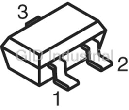
Small Signal Pre-Biased Transistor
Part Number
DTC144EET1
Price
Request Quote
Manufacturer
ON SEMICONDUCTOR
Lead Time
Request Quote
Category
PRODUCTS - D
Datasheet


Extracted Text
DTC114EET1 Series Bias Resistor Transistor NPN Silicon Surface Mount Transistor with Monolithic Bias Resistor Network This new series of digital transistors is designed to replace a single device and its external resistor bias network. The BRT (Bias Resistor http://onsemi.com Transistor) contains a single transistor with a monolithic bias network consisting of two resistors; a series base resistor and a base-emitter resistor. The BRT eliminates these individual components by NPN SILICON integrating them into a single device. The use of a BRT can reduce BIAS RESISTOR both system cost and board space. The device is housed in the TRANSISTORS SC-75/SOT-416 package which is designed for low power surface mount applications. • Simplifies Circuit Design PIN 3 • Reduces Board Space COLLECTOR • Reduces Component Count (OUTPUT) PIN 1 R1 • The SC-75/SOT-416 package can be soldered using BASE wave or reflow. The modified gull-winged leads absorb (INPUT) R2 thermal stress during soldering eliminating the possibility PIN 2 of damage to the die. EMITTER • Available in 8 mm, 7 inch/3000 Unit Tape & Reel (GROUND) MAXIMUM RATINGS (T = 25°C unless otherwise noted) A 3 Rating Symbol Value Unit Collector-Base Voltage V 50 Vdc 2 CBO 1 Collector-Emitter Voltage V 50 Vdc CEO SC-75/SOT-416 Collector Current I 100 mAdc C CASE 463 STYLE 1 MARKING DIAGRAM xx M xx = Specific Device Code (See Marking Table on page 2) M = Date Code Semiconductor Components Industries, LLC, 2003 1 Publication Order Number: March, 2003 - Rev. 5 DTC114EET1/D DTC114EET1 Series DEVICE MARKING AND RESISTOR VALUES Device Marking R1 (K) R2 (K) Shipping DTC114EET1 8A 10 10 3000/Tape & Reel DTC124EET1 8B 22 22 DTC144EET1 8C 47 47 DTC114YET1 8D 10 47 DTC114TET1 94 10 ∞ DTC143TET1 8F 4.7 ∞ DTC123EET1 8H 2.2 2.2 DTC143EET1 8J 4.7 4.7 DTC143ZET1 8K 4.7 47 DTC124XET1 8L 22 47 DTC123JET1 8M 2.2 47 DTC115EET1 8N 100 100 DTC144WET1 8P 47 22 THERMAL CHARACTERISTICS Characteristic Symbol Max Unit Total Device Dissipation, P D FR-4 Board (Note 1) @ T = 25°C 200 mW A Derate above 25°C 1.6 mW/°C Thermal Resistance, Junction-to-Ambient (Note 1) R 600 °C/W θJA Total Device Dissipation, P D FR-4 Board (Note 2) @ T = 25°C 300 mW A Derate above 25°C 2.4 mW/°C Thermal Resistance, Junction-to-Ambient (Note 2) R 400 °C/W θJA Junction and Storage Temperature Range T , T -55 to +150 °C J stg 1. FR-4 @ Minimum Pad 2. FR-4 @ 1.0 × 1.0 Inch Pad http://onsemi.com 2 DTC114EET1 Series ELECTRICAL CHARACTERISTICS (T = 25°C unless otherwise noted) A Characteristic Symbol Min Typ Max Unit OFF CHARACTERISTICS Collector-Base Cutoff Current (V = 50 V, I = 0) I - - 100 nAdc CB E CBO Collector-Emitter Cutoff Current (V = 50 V, I = 0) I - - 500 nAdc CE B CEO Emitter-Base Cutoff Current DTC114EET1 I - - 0.5 mAdc EBO (V = 6.0 V, I = 0) DTC124EET1 - - 0.2 EB C DTC144EET1 - - 0.1 DTC114YET1 - - 0.2 DTC114TET1 - - 0.9 DTC143TET1 - - 1.9 DTC123EET1 - - 2.3 DTC143EET1 - - 1.5 DTC143ZET1 - - 0.18 DTC124XET1 - - 0.13 DTC123JET1 - - 0.2 DTC115EET1 - - 0.05 DTC144WET1 - - 0.13 Collector-Base Breakdown Voltage (I = 10 μA, I = 0) V 50 - - Vdc C E (BR)CBO Collector-Emitter Breakdown Voltage (Note 3) V 50 - - Vdc (BR)CEO (I = 2.0 mA, I = 0) C B ON CHARACTERISTICS (Note 3) DC Current Gain DTC114EET1 h 35 60 - FE (V = 10 V, I = 5.0 mA) DTC124EET1 60 100 - CE C DTC144EET1 80 140 - DTC114YET1 80 140 - DTC114TET1 160 350 - DTC143TET1 160 350 - DTC123EET1 8.0 15 - DTC143EET1 15 30 - DTC143ZET1 80 200 - DTC124XET1 80 150 - DTC123JET1 80 140 - DTC115EET1 80 150 - DTC144WET1 80 140 - Collector-Emitter Saturation Voltage (I = 10 mA, I = 0.3 mA) V - - 0.25 Vdc C B CE(sat) (I = 10 mA, I = 5 mA) DTC123EET1 C B (I = 10 mA, I = 1 mA) DTC143TET1/DTC114TET1/ C B DTC143EET1/DTC143ZET1/DTC124XET1 Output Voltage (on) V Vdc OL (V = 5.0 V, V = 2.5 V, R = 1.0 kΩ) DTC114EET1 - - 0.2 CC B L DTC124EET1 - - 0.2 DTC114YET1 - - 0.2 DTC114TET1 - - 0.2 DTC143TET1 - - 0.2 DTC123EET1 - - 0.2 DTC143EET1 - - 0.2 DTC143ZET1 - - 0.2 DTC124XET1 - - 0.2 DTC123JET1 - - 0.2 (V = 5.0 V, V = 3.5 V, R = 1.0 kΩ) DTC144EET1 - - 0.2 CC B L (V = 5.0 V, V = 5.5 V, R = 1.0 kΩ) DTC115EET1 - - 0.2 CC B L (V = 5.0 V, V = 4.0 V, R = 1.0 kΩ) DTC144WET1 - - 0.2 CC B L Output Voltage (off) (V = 5.0 V, V = 0.5 V, R = 1.0 kΩ) V 4.9 - - Vdc CC B L OH (V = 5.0 V, V = 0.25 V, R = 1.0 kΩ) DTC143TET1 CC B L DTC143ZET1 DTC114TET1 3. Pulse Test: Pulse Width < 300 μs, Duty Cycle < 2.0% http://onsemi.com 3 DTC114EET1 Series ELECTRICAL CHARACTERISTICS (T = 25°C unless otherwise noted) (Continued) A Characteristic Symbol Min Typ Max Unit Input Resistor DTC114EET1 R1 7.0 10 13 kΩ DTC124EET1 15.4 22 28.6 DTC144EET1 32.9 47 61.1 DTC114YET1 7.0 10 13 DTC114TET1 7.0 10 13 DTC143TET1 3.3 4.7 6.1 DTC123EET1 1.5 2.2 2.9 DTC143EET1 3.3 4.7 6.1 DTC143ZET1 3.3 4.7 6.1 DTC124XET1 15.4 22 28.6 DTC123JET1 1.54 2.2 2.86 DTC115EET1 70 100 130 DTC144WET1 32.9 47 61.1 Resistor Ratio DTC114EET1/DTC124EET1/DTC144EET1/ R /R 1 2 DTC115EET1 0.8 1.0 1.2 DTC114YET1 0.17 0.21 0.25 DTC143TET1/DTC114TET1 - - - DTC123EET1/DTC143EET1 0.8 1.0 1.2 DTC143ZET1 0.055 0.1 0.185 DTC124XET1 0.38 0.47 0.56 DTC123JET1 0.038 0.047 0.056 DTC144WET1 1.7 2.1 2.6 250 200 150 100 R = 600°C/W 50 θJA 0 -�50 0 50 100 150 T , AMBIENT TEMPERATURE (°C) A Figure 1. Derating Curve 1.0 D = 0.5 0.2 0.1 0.1 0.05 0.02 0.01 0.01 SINGLE PULSE 0.001 0.00001 0.0001 0.001 0.01 0.1 1.0 10 100 1000 t, TIME (s) Figure 2. Normalized Thermal Response http://onsemi.com 4 r(t), NORMALIZED TRANSIENT THERMAL RESISTANCE P , POWER DISSIPATION (MILLIWATTS) D DTC114EET1 Series TYPICAL ELECTRICAL CHARACTERISTICS - DTC114EET1 1 1000 I /I = 10 V = 10 V C B T �=�-25°C CE A 25°C T �=�75°C A 25°C 0.1 -25°C 75°C 100 0.01 0.001 10 020 40 50 1 10 100 I , COLLECTOR CURRENT (mA) I , COLLECTOR CURRENT (mA) C C Figure 3. V versus I Figure 4. DC Current Gain CE(sat) C 4 100 25°C 75°C f = 1 MHz I = 0 V E T �=�-25°C 10 A T = 25°C 3 A 1 2 0.1 1 0.01 V = 5 V O 0.001 0 010 20 30 40 50 01 2 3 4 56 7 8 9 10 V , REVERSE BIAS VOLTAGE (VOLTS) V , INPUT VOLTAGE (VOLTS) R in Figure 5. Output Capacitance Figure 6. Output Current versus Input Voltage 10 V = 0.2 V T �=�-25°C O A 25°C 75°C 1 0.1 02 10030 40 50 I , COLLECTOR CURRENT (mA) C Figure 7. Input Voltage versus Output Current http://onsemi.com 5 , CAPACITANCE (pF) V , MAXIMUM COLLECTOR VOLTAGE (VOLTS) C CE(sat) ob V , INPUT VOLTAGE (VOLTS) in I , COLLECTOR CURRENT (mA) h , DC CURRENT GAIN (NORMALIZED) C FE DTC114EET1 Series TYPICAL ELECTRICAL CHARACTERISTICS - DTC124EET1 1000 1 V = 10 V CE I /I = 10 C B T �=�75°C A 25°C 25°C T �=�-25°C A 0.1 -25°C 75°C 100 0.01 10 0.001 1 10 100 0 20 40 50 I , COLLECTOR CURRENT (mA) I , COLLECTOR CURRENT (mA) C C Figure 8. V versus I Figure 9. DC Current Gain CE(sat) C 4 100 75°C 25°C f = 1 MHz T �=�-25°C A I = 0 V E 10 3 T = 25°C A 1 2 0.1 1 0.01 V = 5 V O 0 0.001 0 10 203040 50 0 24 68 10 V , REVERSE BIAS VOLTAGE (VOLTS) V , INPUT VOLTAGE (VOLTS) R in Figure 10. Output Capacitance Figure 11. Output Current versus Input Voltage 100 V = 0.2 V O T �=�-25°C A 10 25°C 75°C 1 0.1 0 10 20 30 40 50 I , COLLECTOR CURRENT (mA) C Figure 12. Input Voltage versus Output Current http://onsemi.com 6 C , CAPACITANCE (pF) V , MAXIMUM COLLECTOR VOLTAGE (VOLTS) ob CE(sat) V , INPUT VOLTAGE (VOLTS) in I , COLLECTOR CURRENT (mA) h , DC CURRENT GAIN (NORMALIZED) C FE DTC114EET1 Series TYPICAL ELECTRICAL CHARACTERISTICS - DTC144EET1 10 1000 V = 10 V CE I /I = 10 C B T �=�75°C A 1 25°C -25°C 25°C 100 T �=�-25°C A 75°C 0.1 0.01 10 0 20 40 50 1 10 100 I , COLLECTOR CURRENT (mA) I , COLLECTOR CURRENT (mA) C C Figure 13. V versus I Figure 14. DC Current Gain CE(sat) C 1 100 25°C f = 1 MHz 75°C I = 0 V E 0.8 T �=�-25°C 10 T = 25°C A A 0.6 1 0.1 0.4 0.01 0.2 V = 5 V O 0.001 0 0 1020 3040 50 0 2 468 10 V , REVERSE BIAS VOLTAGE (VOLTS) V , INPUT VOLTAGE (VOLTS) R in Figure 15. Output Capacitance Figure 16. Output Current versus Input Voltage 100 V = 0.2 V O T �=�-25°C A 25°C 10 75°C 1 0.1 010 20 30 40 50 I , COLLECTOR CURRENT (mA) C Figure 17. Input Voltage versus Output Current http://onsemi.com 7 C , CAPACITANCE (pF) V , MAXIMUM COLLECTOR VOLTAGE (VOLTS) ob CE(sat) V , INPUT VOLTAGE (VOLTS) in I , COLLECTOR CURRENT (mA) h , DC CURRENT GAIN (NORMALIZED) C FE DTC114EET1 Series TYPICAL ELECTRICAL CHARACTERISTICS - DTC114YET1 1 300 T �=�75°C A V = 10 I /I = 10 CE C B T �=�-25°C A 250 25°C 25°C 0.1 200 -25°C 75°C 150 0.01 100 50 0.001 0 0 204060 80 1 2468 1015 20 40 50 60 70 80 90 100 I , COLLECTOR CURRENT (mA) I , COLLECTOR CURRENT (mA) C C Figure 18. V versus I Figure 19. DC Current Gain CE(sat) C 4 100 f = 1 MHz T �=�75°C 3.5 A 25°C l = 0 V E 3 T = 25°C A -25°C 2.5 2 10 1.5 1 V = 5 V O 0.5 0 1 02 46 8 10 15 20 2530 35 40 45 50 02 4 6 8 10 V , REVERSE BIAS VOLTAGE (VOLTS) V , INPUT VOLTAGE (VOLTS) R in Figure 20. Output Capacitance Figure 21. Output Current versus Input Voltage 10 V = 0.2 V O T �=�-25°C A 25°C 75°C 1 0.1 010 20 30 40 50 I , COLLECTOR CURRENT (mA) C Figure 22. Input Voltage versus Output Current http://onsemi.com 8 C , CAPACITANCE (pF) V , MAXIMUM COLLECTOR VOLTAGE (VOLTS) ob CE(sat) V , INPUT VOLTAGE (VOLTS) in I , COLLECTOR CURRENT (mA) h , DC CURRENT GAIN (NORMALIZED) C FE DTC114EET1 Series TYPICAL APPLICATIONS FOR NPN BRTs +12 V ISOLATED LOAD FROM μP OR OTHER LOGIC Figure 23. Level Shifter: Connects 12 or 24 Volt Circuits to Logic +12 V V CC OUT IN LOAD Figure 24. Open Collector Inverter: Figure 25. Inexpensive, Unregulated Current Source Inverts the Input Signal http://onsemi.com 9 DTC114EET1 Series INFORMATION FOR USING THE SOT-416 SURFACE MOUNT PACKAGE MINIMUM RECOMMENDED FOOTPRINT FOR SURFACE MOUNTED APPLICATIONS Surface mount board layout is a critical portion of the total interface between the board and the package. With the design. The footprint for the semiconductor packages must correct pad geometry, the packages will self align when be the correct size to insure proper solder connection subjected to a solder reflow process. 0.5 min. (3x) ÉÉÉ ÉÉÉ ÉÉÉ ÉÉÉ TYPICAL SOLDERING PATTERN ÉÉÉ ÉÉÉÉÉÉ Unit: mm ÉÉÉ ÉÉÉ 1.4 SOT-416/SC-90 POWER DISSIPATION The power dissipation of the SOT-416/SC-90 is a func- the equation for an ambient temperature T of 25°C, one A tion of the pad size. This can vary from the minimum pad can calculate the power dissipation of the device which in size for soldering to the pad size given for maximum power this case is 125 milliwatts. dissipation. Power dissipation for a surface mount device is determined by T , the maximum rated junction tem- 150°C - 25°C J(max) P = = 150 milliwatts D 833°C/W perature of the die, Rθ , the thermal resistance from the JA device junction to ambient; and the operating temperature, The 833°C/W assumes the use of the recommended foot- T . Using the values provided on the data sheet, P can be A D print on a glass epoxy printed circuit board to achieve a calculated as follows. power dissipation of 150 milliwatts. Another alternative T - T J(max) A would be to use a ceramic substrate or an aluminum core P = D R θJA board such as Thermal Clad. Using a board material such as Thermal Clad, a higher power dissipation can be The values for the equation are found in the maximum achieved using the same footprint. ratings table on the data sheet. Substituting these values into SOLDERING PRECAUTIONS The melting temperature of solder is higher than the rated • The soldering temperature and time should not exceed temperature of the device. When the entire device is heated 260°C for more than 10 seconds. to a high temperature, failure to complete soldering within • When shifting from preheating to soldering, the a short time could result in device failure. Therefore, the maximum temperature gradient should be 5°C or less. following items should always be observed in order to • After soldering has been completed, the device should minimize the thermal stress to which the devices are be allowed to cool naturally for at least three minutes. subjected. Gradual cooling should be used as the use of forced • Always preheat the device. cooling will increase the temperature gradient and • The delta temperature between the preheat and result in latent failure due to mechanical stress. soldering should be 100°C or less.* • Mechanical stress or shock should not be applied dur- • When preheating and soldering, the temperature of the ing cooling leads and the case must not exceed the maximum * Soldering a device without preheating can cause exces- temperature ratings as shown on the data sheet. When sive thermal shock and stress which can result in damage using infrared heating with the reflow soldering to the device. method, the difference should be a maximum of 10°C. http://onsemi.com 10 0.5 min. (3x) 0.5 1 DTC114EET1 Series SOLDER STENCIL GUIDELINES Prior to placing surface mount components onto a printed The stencil opening size for the surface mounted package circuit board, solder paste must be applied to the pads. A should be the same as the pad size on the printed circuit solder stencil is required to screen the optimum amount of board, i.e., a 1:1 registration. solder paste onto the footprint. The stencil is made of brass or stainless steel with a typical thickness of 0.008 inches. TYPICAL SOLDER HEATING PROFILE For any given circuit board, there will be a group of The line on the graph shows the actual temperature that control settings that will give the desired heat pattern. The might be experienced on the surface of a test board at or operator must set temperatures for several heating zones, near a central solder joint. The two profiles are based on a and a figure for belt speed. Taken together, these control high density and a low density board. The Vitronics settings make up a heating “profile” for that particular SMD310 convection/infrared reflow soldering system was circuit board. On machines controlled by a computer, the used to generate this profile. The type of solder used was computer remembers these profiles from one operating 62/36/2 Tin Lead Silver with a melting point between session to the next. Figure 7 shows a typical heating profile 177-189 °C. When this type of furnace is used for solder for use when soldering a surface mount device to a printed reflow work, the circuit boards and solder joints tend to circuit board. This profile will vary among soldering heat first. The components on the board are then heated by systems but it is a good starting point. Factors that can conduction. The circuit board, because it has a large surface affect the profile include the type of soldering system in area, absorbs the thermal energy more efficiently, then use, density and types of components on the board, type of distributes this energy to the components. Because of this solder used, and the type of board or substrate material effect, the main body of a component may be up to 30 being used. This profile shows temperature versus time. degrees cooler than the adjacent solder joints. STEP 5 STEP 6 STEP 7 STEP 1 STEP 2 STEP 3 STEP 4 HEATING VENT COOLING PREHEAT VENT HEATING HEATING ZONES 4 & 7 ZONE 1 �SOAK" ZONES 2 & 5 ZONES 3 & 6 205° TO 219°C �SPIKE" �RAMP" �RAMP" �SOAK" PEAK AT 200°C 170°C SOLDER JOINT DESIRED CURVE FOR HIGH MASS ASSEMBLIES 160°C 150°C 150°C SOLDER IS LIQUID FOR 40 TO 80 SECONDS 140°C (DEPENDING ON 100°C MASS OF ASSEMBLY) 100°C DESIRED CURVE FOR LOW MASS ASSEMBLIES 50°C TIME (3 TO 7 MINUTES TOTAL) T MAX Figure 26. Typical Solder Heating Profile http://onsemi.com 11 DTC114EET1 Series PACKAGE DIMENSIONS SC-75/SOT-416 CASE 463-01 ISSUE B -A- NOTES: 1. DIMENSIONING AND TOLERANCING PER ANSI S Y14.5M, 1982. 2 2. CONTROLLING DIMENSION: MILLIMETER. MILLIMETERS INCHES 3 G -B- DIM MIN MAX MIN MAX A 0.70 0.80 0.028 0.031 1 B 1.40 1.80 0.055 0.071 D 3 PL C 0.60 0.90 0.024 0.035 M 0.20 (0.008) B D 0.15 0.30 0.006 0.012 0.20 (0.008) A K G 1.00 BSC 0.039 BSC H --- 0.10 --- 0.004 J 0.10 0.25 0.004 0.010 K 1.45 1.75 0.057 0.069 L 0.10 0.20 0.004 0.008 S 0.50 BSC 0.020 BSC J C STYLE 1: PIN 1. BASE 2. EMITTER L 3. COLLECTOR H Thermal Clad is a trademark of the Bergquist Company. ON Semiconductor and are registered trademarks of Semiconductor Components Industries, LLC (SCILLC). SCILLC reserves the right to make changes without further notice to any products herein. SCILLC makes no warranty, representation or guarantee regarding the suitability of its products for any particular purpose, nor does SCILLC assume any liability arising out of the application or use of any product or circuit, and specifically disclaims any and all liability, including without limitation special, consequential or incidental damages. “Typical” parameters which may be provided in SCILLC data sheets and/or specifications can and do vary in different applications and actual performance may vary over time. All operating parameters, including “Typicals” must be validated for each customer application by customer’s technical experts. SCILLC does not convey any license under its patent rights nor the rights of others. SCILLC products are not designed, intended, or authorized for use as components in systems intended for surgical implant into the body, or other applications intended to support or sustain life, or for any other application in which the failure of the SCILLC product could create a situation where personal injury or death may occur. Should Buyer purchase or use SCILLC products for any such unintended or unauthorized application, Buyer shall indemnify and hold SCILLC and its officers, employees, subsidiaries, affiliates, and distributors harmless against all claims, costs, damages, and expenses, and reasonable attorney fees arising out of, directly or indirectly, any claim of personal injury or death associated with such unintended or unauthorized use, even if such claim alleges that SCILLC was negligent regarding the design or manufacture of the part. SCILLC is an Equal Opportunity/Affirmative Action Employer. PUBLICATION ORDERING INFORMATION Literature Fulfillment: JAPAN: ON Semiconductor, Japan Customer Focus Center Literature Distribution Center for ON Semiconductor 2-9-1 Kamimeguro, Meguro-ku, Tokyo, Japan 153-0051 P.O. Box 5163, Denver, Colorado 80217 USA Phone: 81-3-5773-3850 Phone: 303-675-2175 or 800-344-3860 Toll Free USA/Canada ON Semiconductor Website: http://onsemi.com Fax: 303-675-2176 or 800-344-3867 Toll Free USA/Canada Email: ONlit@hibbertco.com For additional information, please contact your local Sales Representative. N. American Technical Support: 800-282-9855 Toll Free USA/Canada DTC114EET1/D http://onsemi.com 12
Frequently asked questions
What makes Elite.Parts unique?

What kind of warranty will the DTC144EET1 have?
Which carriers does Elite.Parts work with?
Will Elite.Parts sell to me even though I live outside the USA?
I have a preferred payment method. Will Elite.Parts accept it?








What they say about us
FANTASTIC RESOURCE
One of our top priorities is maintaining our business with precision, and we are constantly looking for affiliates that can help us achieve our goal. With the aid of GID Industrial, our obsolete product management has never been more efficient. They have been a great resource to our company, and have quickly become a go-to supplier on our list!
Bucher Emhart Glass
EXCELLENT SERVICE
With our strict fundamentals and high expectations, we were surprised when we came across GID Industrial and their competitive pricing. When we approached them with our issue, they were incredibly confident in being able to provide us with a seamless solution at the best price for us. GID Industrial quickly understood our needs and provided us with excellent service, as well as fully tested product to ensure what we received would be the right fit for our company.
Fuji
HARD TO FIND A BETTER PROVIDER
Our company provides services to aid in the manufacture of technological products, such as semiconductors and flat panel displays, and often searching for distributors of obsolete product we require can waste time and money. Finding GID Industrial proved to be a great asset to our company, with cost effective solutions and superior knowledge on all of their materials, it’d be hard to find a better provider of obsolete or hard to find products.
Applied Materials
CONSISTENTLY DELIVERS QUALITY SOLUTIONS
Over the years, the equipment used in our company becomes discontinued, but they’re still of great use to us and our customers. Once these products are no longer available through the manufacturer, finding a reliable, quick supplier is a necessity, and luckily for us, GID Industrial has provided the most trustworthy, quality solutions to our obsolete component needs.
Nidec Vamco
TERRIFIC RESOURCE
This company has been a terrific help to us (I work for Trican Well Service) in sourcing the Micron Ram Memory we needed for our Siemens computers. Great service! And great pricing! I know when the product is shipping and when it will arrive, all the way through the ordering process.
Trican Well Service
GO TO SOURCE
When I can't find an obsolete part, I first call GID and they'll come up with my parts every time. Great customer service and follow up as well. Scott emails me from time to time to touch base and see if we're having trouble finding something.....which is often with our 25 yr old equipment.
ConAgra Foods
FANTASTIC RESOURCE
One of our top priorities is maintaining our business with precision, and we are constantly looking for affiliates that can help us achieve our goal. With the aid of GID Industrial, our obsolete product management has never been more efficient. They have been a great resource to our company, and have quickly become a go-to supplier on our list!
Bucher Emhart Glass
EXCELLENT SERVICE
With our strict fundamentals and high expectations, we were surprised when we came across GID Industrial and their competitive pricing. When we approached them with our issue, they were incredibly confident in being able to provide us with a seamless solution at the best price for us. GID Industrial quickly understood our needs and provided us with excellent service, as well as fully tested product to ensure what we received would be the right fit for our company.
Fuji
HARD TO FIND A BETTER PROVIDER
Our company provides services to aid in the manufacture of technological products, such as semiconductors and flat panel displays, and often searching for distributors of obsolete product we require can waste time and money. Finding GID Industrial proved to be a great asset to our company, with cost effective solutions and superior knowledge on all of their materials, it’d be hard to find a better provider of obsolete or hard to find products.
Applied Materials
CONSISTENTLY DELIVERS QUALITY SOLUTIONS
Over the years, the equipment used in our company becomes discontinued, but they’re still of great use to us and our customers. Once these products are no longer available through the manufacturer, finding a reliable, quick supplier is a necessity, and luckily for us, GID Industrial has provided the most trustworthy, quality solutions to our obsolete component needs.
Nidec Vamco
TERRIFIC RESOURCE
This company has been a terrific help to us (I work for Trican Well Service) in sourcing the Micron Ram Memory we needed for our Siemens computers. Great service! And great pricing! I know when the product is shipping and when it will arrive, all the way through the ordering process.
Trican Well Service
GO TO SOURCE
When I can't find an obsolete part, I first call GID and they'll come up with my parts every time. Great customer service and follow up as well. Scott emails me from time to time to touch base and see if we're having trouble finding something.....which is often with our 25 yr old equipment.
ConAgra Foods