

 Manufacturers
OMRON H7AN

Description
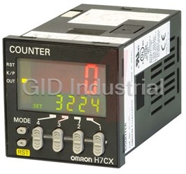
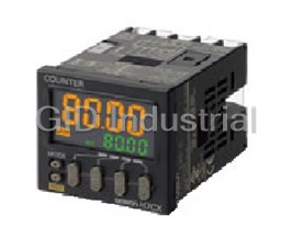
Omron H7AN Counter/Timer Modules-Digital Counter (DIN 72 × 72)
Part Number
H7AN
Price
Request Quote
Manufacturer
OMRON
Lead Time
Request Quote
Category
PRODUCTS - H
Specifications
Dielectric strength
2,000 VAC, 50/60 Hz for 1 min
External power supply
80 mA, 12 VDC ±10% (contains 5% ripple max.)
Insulation resistance
100 MW min. (at 500 VDC)
Max. counting speed of CP1 and CP2
2-digit counters: 30 Hz,4-digit counters: 30 Hz or 5 kHz
Min. applicable load
10 mA at 5 VDC (p level reference value)
Operating voltage range
85% to 110% of rated voltage
Power consumption
Approx. 10 VA (240 VAC at 50 Hz); Approx. 5 W (at 24 VDC)
Rated supply voltage
100 to 240 VAC, 50/60 Hz (common use); 12 to 24, 48, 100 VDC*
Weight
Approx. 360 g
Features
- A draw-out construction enables maintenance without rewiring.
- Easy setting with thumbwheel switches.
- Models with 2-, 4-, 6-, or 8-digit displays are also available.
- Total Counter models are also Available.
Datasheet

Extracted Text
Digital Counter (DIN 72 × 72) H7AN CSM_H7AN_DS_E_3_1 A DIN 72 x 72 mm Best-selling Counter • Easy setting with thumbwheel switches. A draw-out construction enables maintenance without rewiring. Models with 2-, 4-, 6-, or 8-digit displays are also available. Total Counter models are also Available. Complies with UL and CSA Marking. Refer to Safety Precautions for All Counters and Safety Precautions on page 17. This product was upgraded in January 2006. Refer to Changes in Specifications on page 18 for details. 1 H7AN Ordering Information Each model is sold together with a mounting bracket. Preset Counter Incrementing (Up) or decrementing Reversible counter (Up/Down) (Down) counter (not reversible) One stage Two stages One stage Two stages With digital With digital With digital With digital display display display display Backup No. of Backup No. of function digits function digits No H7AN-E2D --- No H7AN-2D --- 2 2 Yes H7AN-E2DM --- Yes H7AN-2DM --- No H7AN-E4D H7AN-WE4D No H7AN-4D H7AN-W4D 4 4 Yes H7AN-E4DM H7AN-WE4DM Yes H7AN-4DM H7AN-W4DM Incrementing (Up), decrementing (Down), or reversible (Up/Down) counter One stage Two stages With digital With digital display display No. of Backup function digits No H7AN-R6D H7AN-RW6D 6 Yes H7AN-R6DM H7AN-RW6DM No H7AN-R8D --- 8 Yes H7AN-R8DM --- Totalizing Counter Incrementing (Up) or decrementing Reversible counter Reversible counter (Down) counter (not reversible) (Up/Down) (Up/Down) No. of Backup No. of Backup digits digits function function No H7AN-RT6 No H7AN-T4 H7AN-ET4 4 6 Yes H7AN-T4M H7AN-ET4M Yes H7AN-RT6M No H7AN-RT8 8 Yes H7AN-RT8M Note: Specify the power supply voltage when ordering. 2 H7AN Specifications Preset Counters Incrementing/Decrementing Counters Operating method Incrementing and decrementing (selectable with DIP switch) Mounting method Flush mounting Operation modes N, F, C, R, K, P, Q (selectable with rotary DIP switch) Input signal method (Count and reset Contact and solid-state input voltage (H and L) inputs) Control output 1-stage counters: Contact (SPDT) and solid-state output (H and L output switchable) 2-stage counters: Contact (SPST-NO) and solid-state output (H and L output switchable) Set value read Continuous mode Memory backup No Yes/No (Selectable using DIP switch) Display Yes (10-mm high 7-segment LED, Up indicator) Yes (10-mm high 7-segment LED, Up indicator) Models 2 digits 1 stage H7AN-2D H7AN-2DM 4 digits 1 stage H7AN-4D H7AN-4DM 2 stages H7AN-W4D H7AN-W4DM Reversible Counters Operating method Reversible (selectable with rotary DIP switch) between 0 and the set value Incrementing/decrementing A/D (command inputs) Incrementing/decrementing B/E (individual inputs) Incrementing/decrementing C/F (phase difference inputs) Mounting method Flush mounting Operation modes N, F, C, R, K, P, Q (selectable with rotary DIP switch) Input signal method (Count, reset Contact and solid-state input voltage (H and L) input) Control output 1-stage counters: Contact (SPDT) and solid-state output (H and L output switchable) 2-stage counters: Contact (SPST-NO) and solid-state output (H and L output switchable) Set value read Continuous mode Memory backup No Yes/No (Selectable using DIP switch) Display Yes (10-mm high 7-segment LED) Models 2 digits 1 stage H7AN-E2D H7AN-E2DM 4 digits 1 stage H7AN-E4D H7AN-E4DM 2 stages H7AN-WE4D H7AN-WE4DM Incrementing, Decrementing, and Reversible Counters Operating method Incrementing, decrementing, and reversible (UP/DOWN A to F) (selectable with rotary DIP switch) Mounting method Flush mounting Operation modes N, F, C, R, K, P, Q (selectable with rotary DIP switch) Input signal method (Count, reset Contact and solid-state input voltage (H and L) input) Control output 1-stage counters: Contact (SPDT) and solid-state output (H and L output switchable) 2-stage counters: Contact (SPST-NO) and solid-state output (H and L output switchable) Set value read Continuous mode, Reset mode (selectable) Memory backup No Yes/No (Selectable using DIP switch) Display Yes (8-mm high 7-segment LED, Up indicator) Models 6 digits 1 stage H7AN-R6D H7AN-R6DM 2 stage H7AN-RW6D H7AN-RW6DM 8 digits 1 stages H7AN-R8D H7AN-R8DM 3 H7AN Totalizing Counters Incrementing/Decrementing Counters Operating method Incrementing and decrementing (selectable with DIP switch) Mounting method Flush mounting Input signal method (Count, reset input) Contact and solid-state input voltage (H and L) Memory backup No Yes/No (Selectable using DIP switch) Display Yes (10-mm high 7-segment LED) Models 4 digits H7AN-T4 H7AN-T4M Reversible Counters Operating method Reversible (selectable with rotary DIP switch) between 0 and the full scale Incrementing/decrementing A/D (command inputs) Incrementing/decrementing B/E (individual inputs) Incrementing/decrementing C/F (phase difference inputs) Mounting method Flush mounting Input signal method (Count, reset input) Contact and solid-state input voltage (H and L) Memory backup No Yes/No (Selectable using DIP switch) Display Yes (10-mm high 7-segment LED) Models 4 digits H7AN-ET4 H7AN-ET4M Incrementing, Decrementing, and Reversible Counters Operating method Incrementing, decrementing, and reversible (UP/DOWN A to F) Mounting method Flush mounting Input signal method (Count, reset input) Contact and solid-state input voltage (H and L) Memory backup No Yes/No (Selectable using DIP switch) Display Yes (8-mm high 7-segment LED) Models 6 digits H7AN-RT6 H7AN-RT6M 8 digits H7AN-RT8 H7AN-RT8M ■ Ratings Rated supply voltage 100 to 240 VAC, 50/60 Hz (common use); 12 to 24, 48, 100 VDC* Operating voltage range 85% to 110% of rated voltage Power consumption Approx. 10 VA (240 VAC at 50 Hz); Approx. 5 W (at 24 VDC)** Max. counting speed of 2-digit counters: 30 Hz CP1 and CP2 4-digit counters: 30 Hz or 5 kHz 6- or 8-digit counters: 30 Hz or 5 kHz Minimum signal width (with ON/OFF ratio of 1:1): 30 Hz: 16.7 ms, 5 kHz: 0.1 ms H: 4.5 to 30 VDC, L: 0 to 2 VDC Reset Power supply reset (except for H7AN Counter with suffix “-M”): Minimum power-OFF time: 0.5 s with a reset time of 0.05 s after power-ON. External, manual, reset signal time: 0.02 s Reset time after completion of reset signal: 0.05 s Automatic reset*** Control output Contacts: 3 A at 250 VAC, resistive load (cosφ = 1) No-contacts: 100 mA max. at 30 VDC max., open collector Min. applicable load 10 mA at 5 VDC (p level reference value) External power supply 80 mA, 12 VDC ±10% (contains 5% ripple max.) Ambient temperature Operating: –10°C to 55°C (with no icing) Storage: –25°C to 65°C (with no icing) Ambient humidity 35% to 85% Case Light gray (Munsell 5Y7/1) *The ripple is 20% max. **There is an inrush current of 14 A at 240 VAC for approximately 0.6 ms, 15 A at 12 to 24 VDC for 2 ms, 5 A at 48 VDC for 3 ms, or 8 A at 100 VDC for 2 ms immediately after power-ON. ***Only preset counters can be automatically reset. 4 H7AN ■ Characteristics Insulation resistance 100 MW min. (at 500 VDC) (between current-carrying terminal and exposed non-current-carrying metal parts, and between non-continuous contacts) Dielectric strength 2,000 VAC, 50/60 Hz for 1 min (between current-carrying terminal and exposed non-current carrying metal parts) 750 VAC, 50/60 Hz for 1 min (between non-continuous contacts) Impulse withstand voltage 6 kV (between power terminals), 6 kV (between current-carrying terminal and exposed non-current-carrying metal parts) Noise immunity ±2 kV (between power terminals) and ±500 V (between input terminals), square-wave noise by noise simulator Vibration resistance Destruction:10 to 55 Hz, 0.75-mm double amplitude Malfunction:10 to 55 Hz, 0.5-mm double amplitude 2 Shock resistance Destruction: 300 m/s 2 Malfunction: 100 m/s Life expectancy Mechanical: 10,000,000 operations min. Electrical: 100,000 operations min. (3 A at 250 VAC, resistive load) Approved standards UL508, CSA C22.2 No.14 Weight Approx. 360 g Engineering Data Life of Contacts Electric Life Expectancy Electric Life Expectancy (Resistive load) (Inductive load) Reference: 0.15 A max. can be switched 100,000 30 VDC (cosφ = 1) 30 VDC (L/R=7ms) times at 125 VDC (cosφ = 1). 0.1 A max. can be switched 100,000 times when L/R = 7 ms. 250 VAC (cosφ = 1) 250 VAC (cosφ = 0.4) Load current (A) Load current (A) 5 3 No. of operations (×10 ) 3 No. of operations (×10 ) H7AN Operation ■ Count Operation Preset Counters Incrementing/Decrementing selectable mode Reversible mode Incrementing mode Incrementing/Decrementing A, B, C (incrementing) mode Reset Reset 2nd 2nd Preset Preset 1st 1st Display Display 0 0 Count out Count out 1st 1st Control outputs Control outputs Count out Count out 2nd 2nd Decrementing mode Incrementing/Decrementing D, E, F (decrementing) mode Reset Reset 2nd 2nd Preset Preset Display Display 1st 1st 0 0 Count out Count out 1st 1st Control outputs Control outputs Count out Count out 2nd 2nd Note: Two-stage counters, set the counters so that the interval between 1st and 2nd count out will be more than 5 ms. For Incrementing/ Decrementing switchable counters, only the 2nd value will be effective if the 1st value is larger than the 2nd value. The Incrementing/Decrementing Counters give outputs in the following order; 1st to 2nd to 1st to 2nd. Totalizing Counters Incrementing/Decrementing selectable mode Reversible mode Incrementing mode Incrementing/Decrementing A, B, C (decrementing) mode Reset Reset Full scale* Full scale* Display Display 0 0 Decrementing mode Incrementing/Decrementing D, E, F (decrementing) mode Reset Reset Full scale* Full scale* Display Display 0 0 Note: The count value will return to “0” when it reaches the full scale limit. * The full scale value is 9999 for the 4-digit counters, 999999 for the 6-digit counters, and 99999999 for the 8-digit counters. 6 H7AN ■ *Output Timing Charts 1-stage Counters 2-stage Counters 1st stage: count out Start Count out 2nd stage: count out Start Count Count ON ON OFF OFF Contact output Load Load ON ON Solid-state output Contact outputs OFF OFF Phase (H to L) Load OFF ON Loads OFF OFF Phase (L to H) * Phase (H to L) ON * The operation of the load when the Loads OFF phase has been reversed. Phase (L to H) * ON Solid-state outputs OFF Phase (H to L) ON Loads OFF Phase (L to H) * * The operation of the load when the phase has been reversed. Output Delays Control output Max. counting speed Output delay 2-, 4-digit counters 6-, 8-digit counters Contact output 30 Hz 14.0 to 16.0 ms 14.0 to 18.0 ms 5 kHz 6.0 to 8.0 ms 6.0 to 8.0 ms Solid-state output 30 Hz 8.0 to 10.0 ms 9.5 to 12.0 ms 5 kHz 0.4 to 0.6 ms 0.3 to 0.5 ms Input Mode Setting Incrementing/Decrementing Selectable Mode Note: The width of (A) must be the same as or lager than the minimum signal width, because an error of ±1 count may occur if the width of (A) is smaller than the minimum signal width. Incrementing mode Decrementing mode CP1: Count input; CP2: prohibit (gate) input CP1: Count input; CP2: prohibit (gate) input H H CP1 CP1 L (A) L (A) (A) (A) Prohibited Prohibited H H CP2 CP2 L L n 5 4 n − 1 Count Count n − 2 3 n − 3 2 n − 4 1 n − 5 0 0 0 CP1: Prohibit (gate) input; CP2: count input CP1: Prohibit (gate) input; CP2: count input H H CP1 CP1 L L (A) (A) (A) (A) Prohibited Prohibited H H CP2 CP2 L L n 5 n − 1 4 Count n − 2 Count 3 n − 3 2 n − 4 1 n − 5 0 0 0 7 H7AN Reversible Mode Note: 1. A: Minimum signal width; B: Must be at least 1/2 of minimum signal width. An error of ±1 count may occur if the width of (A) and (B) are smaller than the minimum signal width. 2. Set the same counting speed for CP1 and CP2 when in Up/Down C, or F mode. Incrementing mode Decrementing mode Incrementing/Decrementing A command input mode Incrementing/Decrementing D command input mode H H CP1 CP1 L L (A) (A) (A) (A) H H CP2 CP2 L L n Count 3 Count 3 n − 1 n − 1 2 2 2 n − 2 n − 2 n − 2 1 1 n − 3 n − 3 0 0 0 0 Incrementing/Decrementing E individual input mode Incrementing/Decrementing B individual input mode H H CP1 CP1 L L (A) H H CP2 CP2 L L n Count Count 3 3 n − 1n − 1 n − 1 2 22 n − 2 n − 2 n − 2 1 1 1 n − 3 n − 3 0 0 0 0 Incrementing/Decrementing C phase difference input mode Incrementing/Decrementing F phase difference input mode H H CP1 CP1 L L BBBB BBBB H H CP2 CP2 L L n Count Count 3 3 n − 1 n − 1 2 22 n − 2 n − 2 n − 2 1 1 n − 3 n − 3 0 0 0 ■ Output Modes Incrementing, decrementing, or reversible One-shot 1st output (0.5 s, fixed) Only CP2 is effective for 1-stage digital counters. Self-holding output Self-holding output One-shot 2nd output (0.1 to 1 s, variable) Note: 1. In the C, K, P, and Q modes, the counters must not count out again while the one-shot timer is working. 2. In the C mode, the present value is placed in reset start status as soon as the preset count is reached and the count-out status is not displayed. Output Incrementing, Incrementing/Decrementing A, B, C Decrementing, Incrementing/Decrementing D, E, F mode N Reset Reset 2nd 2nd Display1st Display1st 0 0 1st output 1st output 2nd output 2nd output 8 H7AN Output Incrementing, Incrementing/Decrementing A, B, C Decrementing, Incrementing/Decrementing D, E, F mode F Reset Reset 2nd 2nd Display1st Display1st 0 0 1st output 1st output 2nd output 2nd output C Reset Reset 2nd 2nd Display1st Display1st 0 0 1st output 1st output 2nd output 2nd output R Reset Reset 2nd 2nd Display1st Display 1st 0 0 1st output 1st output 2nd output 2nd output K Reset Reset 2nd 2nd 2nd Display1st Display1st 0 0 1st output 1st output 1st output 2nd output 2nd output P Reset Reset Reset 2nd 2nd 2nd Display1st Displa Display y1st 1st 0 0 0 1st output 1st output 1st output 2nd output 2nd output Q Reset Reset 2nd 2nd Display 1st Display 1st 0 0 1st output 1st output 2nd output 2nd output 9 H7AN Nomenclature ■ Nomenclature Preset Counter H7AN-2D, -2DM H7AN-4D, -4DM H7AN-E2D, -E2DM H7AN-E4D, -E4DM Seven-segment LED digital display Seven-segment LED digital display Indicator lights at count-out Indicator lights at count-out Indicator lights when reset input is received Indicator lights when reset input is received Pushbutton switch for manual reset Pushbutton switch for manual reset Internal Unit mounting screw Internal Unit mounting screw One-shot timer adjuster One-shot timer adjuster Front cover Front cover Arrangement and Functions of Specification Selection Switches Arrangement and Functions of Specification Selection Switches H7AN-2D (Counting speed: 30 Hz only) H7AN-E2D (Counting speed: 30 Hz only) H7AN-4D H7AN-E4D 1 2 3 1 2 1 2 1 2 3 1 2 1 2 SW4 SW4 SW3 SW4 SW3 SW4 SW2 SW1 SW2 SW2 SW1 SW2 SW2: (A) Operating mode selector SW1: (A) Counting function selector SW2: (A) Operating mode selector SW1: (A) Counting function selector SW4-1: Output phase selector for SW2: (A) Operating mode selector SW3-1: CP1 maximum counting SW2: (A) Operating mode selector speed selector transistor output section SW4-1: Output phase selector for SW3-1: CP1 maximum counting L→H (at count-out) 30 Hz (See note.) transistor output section speed selector (See note.) 5 kHz L→H (at count-out) 30 Hz (See note.) H→L (at count-out) (See note.) SW3-2: CP2 maximum counting 5 kHz SW4-2: Manual reset selector H→L (at count-out) speed selector SW3-2: CP2 maximum counting Manual reset possible 30 Hz (See note.) SW4-2: Manual reset selector speed selector (See note.) 5 kHz Manual reset possible 30 Hz (See note.) Manual reset not possible (See note.) SW4-1: Output phase selector for 5 kHz SW4-3: UP/DOWN selector Manual reset not possible transistor output section SW4-1: Output phase selector for Up counting (incrementing) L→H (at count-out) transistor output section (See note.) (See note.) L→H (at count-out) Down counting H→L (at count-out) (See note.) (decrementing) SW4-2: Manual reset selector H→L (at count-out) Manual reset possible SW4-2: Manual reset selector (See note.) Manual reset possible Manual reset not possible (See note.) SW4-3: UP/DOWN selector Manual reset not possible Up counting (incrementing) (See note.) Down counting (decrementing) H7AN-2DM (Counting speed: 30 Hz only) H7AN-E2DM(Counting speed: 30 Hz only) H7AN-4DM H7AN-E4DM 1 1 2 3 1 1 2 1 2 3 1 2 3 1 2 3 1 2 SW3 SW4 SW3 SW4 SW3 SW4 SW3 SW4 SW2 SW1 SW2 SW2 SW1 SW2 SW2: (A) Operating mode selector SW1: (A) Counting function selector SW2: (A) Operating mode selector SW1: (A) Counting function selector SW3: Power failure memory backup SW2: (A) Operating mode selector SW3-1: CP1 maximum counting SW2: (A) Operating mode selector Memory backup speed selector SW3: Power failure memory backup SW3-1: CP1 maximum counting 30 Hz (See note.) (See note.) Memory backup speed selector 5 kHz No memory backup (See note.) 30 Hz (See note.) SW3-2: CP2 maximum counting SW4-1: Output phase selector for No memory backup 5 kHz speed selector transistor output section SW4-1: Output phase selector for SW3-2: CP2 maximum counting 30 Hz (See note.) L→H (at count-out) transistor output section speed selector 5 kHz (See note.) L→H (at count-out) 30 Hz (See note.) SW3-3: SW3-3: Power failure H→L (at count-out) (See note.) memory backup 5 kHz SW4-2: Manual reset selector H→L (at count-out) Memory backup (See note.) SW3-3: Power failure memory backup Manual reset possible SW4-2: Manual reset selector No memory backup Memory backup (See note.) Manual reset possible SW4-1: Output phase selector for (See note.) Manual reset not possible (See note.) transistor output section No memory backup SW4-3: UP/DOWN selector Manual reset not possible L→H (at count-out) (See note.) SW4-1: Output phase selector for Up counting (incrementing) H→L (at count-out) transistor output section (See note.) SW4-2: Manual reset selector L→H (at count-out) Down counting Manual reset possible (See note.) (decrementing) (See note.) H→L (at count-out) Manual reset not possible SW4-2: Manual reset selector SW4-3: UP/DOWN selector Manual reset possible Up counting (incrementing) (See note.) (See note.) Manual reset not possible Down counting (decrementing) Note: These settings are the defaults for the specification selection switches. 10 H7AN H7AN-W4D, -W4DM H7AN-R6D, -R6DM H7AN-WE4D, -WE4DM H7AN-R8D, -R8DM Seven-segment LED digital display Seven-segment LED digital display Indicator lights at count-out Indicator lights at count-out Indicator lights at count-out Indicator lights when Indicator lights when Indicator lights when reset input is received reset input is received reset input is received Pushbutton switch for manual reset Pushbutton switch for Pushbutton switch for manual reset manual reset Internal Unit mounting screw Internal Unit mounting screw Internal Unit mounting screw One-shot timer adjuster One-shot timer adjuster One-shot timer adjuster Front cover Front cover Front cover Arrangement and Functions of Specification Selection Switches Arrangement and Functions of Specification Selection Switches H7AN-W4D H7AN-WE4D H7AN-R6D, -R8D 1 2 1 2 3 4 1 2 1 2 3 1 2 1 2 3 SW3 SW4 SW3 SW4 SW3 SW4 SW2 SW1 SW2 SW1 SW2 SW2: (B) Operating mode selector SW1: (A) Counting function selector SW1: (B) Counting function selector SW3-1: CP1 maximum counting SW2: (B) Operating mode selector SW2: (A) Operating mode selector speed selector SW3-1: CP1 maximum counting SW3-1: CP1 maximum counting 30 Hz (See note.) speed selector speed selector 5 kHz 30 Hz (See note.) 30 Hz (See note.) SW3-2: CP2 maximum counting 5 kHz 5 kHz speed selector SW3-2: CP2 maximum counting SW3-2: CP2 maximum counting 30 Hz (See note.) speed selector 5 kHz speed selector 30 Hz (See note.) SW4-1: Output phase selector for 30 Hz (See note.) 5 kHz first transistor output section 5 kHz L→H (at count-out) SW4-1: Output phase selector for SW4-1: Output phase selector for (See note.) first transistor output section transistor output section H→L (at count-out) L→H (at count-out) L→H (at count-out) SW4-2: Output phase selector for (See note.) (See note.) second transistor output section H→L (at count-out) L→H (at count-out) H→L (at count-out) SW4-2: Output phase selector for (See note.) SW4-2: Set value read selector second transistor output section H→L (at count-out) Always read (See note.) L→H (at count-out) SW4-3: Manual reset selector Read only at reset (See note.) Manual reset possible (See note.) H→L (at count-out) SW4-3: Manual reset selector Manual reset not possible SW4-3: Manual reset selector Manual reset possible SW4-4: UP/DOWN selector Manual reset possible (See note.) Up counting (incrementing) (See note.) Manual reset not possible (See note.) Manual reset not possible Down counting (decrementing) H7AN-W4DM H7AN-WE4DM H7AN-R6DM, -R8DM 1 2 3 1 2 3 4 1 2 3 1 2 3 1 2 3 1 2 3 SW3 SW4 SW3 SW4 SW3 SW4 SW2 SW1 SW2 SW1 SW2 SW2: (B) Operating mode selector SW1: (A) Counting function selector SW1: (B) Counting function selector SW3-1: CP1 maximum counting SW2: (B) Operating mode selector SW2: (A) Operating mode selector speed selector SW3-1: CP1 maximum counting SW3-1: CP1 maximum counting 30 Hz (See note.) speed selector speed selector 5 kHz 30 Hz (See note.) 30 Hz (See note.) SW3-2: CP2 maximum counting 5 kHz 5 kHz speed selector SW3-2: CP2 maximum counting SW3-2: CP2 maximum counting 30 Hz (See note.) speed selector speed selector 5 kHz 30 Hz (See note.) 30 Hz (See note.) SW3-3: Power failure memory backup 5 kHz 5 kHz Memory backup (See note.) SW3-3: Power failure memory backup No memory backup SW3-3: Power failure memory backup Memory backup SW4-1: Output phase selector for first Memory backup (See note.) transistor output section (See note.) No memory backup L→H (at count-out) No memory backup SW4-1: Output phase selector for (See note.) SW4-1: Output phase selector for first transistor output section H→L (at count-out) L→H (at count-out) transistor output section SW4-2: Output phase selector for (See note.) L→H (at count-out) second transistor output section H→L (at count-out) (See note.) L→H (at count-out) SW4-2: Output phase selector for second (See note.) H→L (at count-out) transistor output section H→L (at count-out) SW4-2: Set value read selector L→H (at count-out) SW4-3: Manual reset selector Always read (See note.) (See note.) Manual reset possible Read only at reset H→L (at count-out) (See note.) SW4-3: Manual reset selector SW4-3: Manual reset selector Manual reset not possible Manual reset possible Manual reset possible SW4-4: UP/DOWN selector Up counting (incrementing) (See note.) (See note.) (See note.) Manual reset not possible Manual reset not possible Down counting (decrementing) Note: These settings are the defaults for the specification selection switches. 11 H7AN Totalizing Counter H7AN-RW6D, -RW6DM H7AN-T4, -T4M, -ET4, -ET4M H7AN-RT6, -RT6M, -RT8, -RT8M Seven-segment LED Seven-segment LED digital display digital display Indicator lights at count-out Indicator lights when Indicator lights when reset input is received reset input is received Pushbutton switch for manual reset Pushbutton switch for manual reset Internal Unit mounting screw Internal Unit mounting screw One-shot timer adjuster Front cover Front cover Arrangement and Functions of Specification Selection Switches Arrangement and Functions of Specification Selection Switches H7AN-RW6D H7AN-T4 H7AN-ET4 H7AN-RT6, -RT8 1 2 1 2 3 4 1 2 1 2 1 2 1 1 2 1 SW3 SW4 SW3 SW4 SW3 SW4 SW3 SW4 SW1 SW2 SW1 SW1 SW1: (B) Counting function selector SW1: (B) Counting function selector SW3-1: CP1 maximum counting SW1: (A) Counting function selector SW2: (B) Operating mode selector speed selector SW3-1: CP1 maximum counting SW3-1: CP1 maximum counting 30 Hz (See note 1.) SW3-1: CP1 maximum counting speed selector speed selector 5 kHz speed selector 30 Hz (See note 1.) 30 Hz (See note 1.) 30 Hz (See note 1.) SW3-2: CP2 maximum counting 5 kHz 5 kHz 5 kHz speed selector SW3-2: CP2 maximum counting SW3-2: CP2 maximum counting SW3-2: SW3-2: CP2 maximum 30 Hz (See note 1.) speed selector speed selector counting speed selector 5 kHz 30 Hz (See note 1.) 30 Hz (See note 1.) 30 Hz (See note 1.) SW4-1: Manual reset selector 5 kHz 5 kHz 5 kHz Manual reset possible SW4-1: Output phase selector for first SW4: Manual reset selector SW4: Manual reset selector (See note 1.) transistor output section Manual reset possible Manual reset possible Manual reset not possible L→H (at count-out) (See note 1.) (See note 1.) (See note 1.) SW4-2: UP/DOWN selector Manual reset not possible Manual reset not possible H→L (at count-out) Up counting (incrementing) SW4-2: Output phase selector for (See note 1.) second transistor output section Down counting L→H (at count-out) (decrementing) (See note 1.) H→L (at count-out) SW4-3: Set value read selector Always read (See note 1.) H7AN-T4M H7AN-ET4M H7AN-RT6M, -RT8M Read only at reset SW4-4: Manual reset selector Manual reset possible 1 2 3 1 2 1 2 3 1 1 2 3 1 (See note 1.) SW3 SW4 SW3 SW4 SW3 SW4 Manual reset not possible SW1 SW1 H7AN-RW6DM SW3-1: CP1 maximum counting SW1: (A) Counting function selector SW1: (B) Counting function selector 1 2 3 1 2 3 4 speed selector SW3-1: CP1 maximum counting SW3-1: CP1 maximum counting SW3 SW4 30 Hz (See note 1.) speed selector speed selector 5 kHz SW1 SW2 30 Hz (See note 1.) 30 Hz (See note 1.) SW3-2: CP2 maximum counting 5 kHz 5 kHz speed selector SW3-2: CP2 maximum SW3-2: CP2 maximum counting 30 Hz (See note 1.) 5 kHz counting speed selector speed selector SW1: (B) Counting function selector SW3-3: Power failure memory backup 30 Hz (See note 1.) 30 Hz (See note 1.) Memory backup (See note 1.) SW2: (B) Operating mode selector 5 kHz 5 kHz No memory backup SW3-1: CP1 maximum counting SW3-3: Power failure memory backup SW3-3: Power failure memory backup SW4-1: Manual reset selector speed selector Memory backup (See note 1.) Memory backup (See note 1.) Manual reset possible 30 Hz (See note 1.) No memory backup No memory backup (See note 1.) 5 kHz Manual reset not possible SW4: Manual reset selector SW4: Manual reset selector SW3-2: CP2 maximum counting SW4-2: UP/DOWN selector Manual reset possible Manual reset possible speed selector Up counting (incrementing) (See note 1.) (See note 1.) (See note 1.) 30 Hz (See note 1.) Manual reset not possible Manual reset not possible 5 kHz Down counting (decrementing) SW3-3: Power failure memory backup Memory backup (See note 1.) No memory backup Note: 1. These settings are the defaults for the specification selection SW4-1: Output phase selector for switches. first transistor output section L→H (at count-out) 2. Specifications selected using the internal specification selection (See note 1.) switches become after switching once a reset has been H→L (at count-out) performed (e.g., power supply reset, external reset, or manual SW4-2: Output phase selector for second transistor output section reset, but not automatic reset). L→H (at count-out) If a reset is not performed, operation will continue with the (See note 1.) specifications before switching. H→L (at count-out) SW4-3: Set value read selector Always read (See note 1.) Read only at reset SW4-4: Manual reset selector Manual reset possible (See note 1.) Manual reset not possible 12 H7AN SW1 (A) Counting function selector SW2 (A) Operating mode selector (1-stage preset models) Switch Function position Switch Function position 0, 1, 8, 9 Up/Down A (command inputs) (See note.) 0, 7, 8, F N (count stop, output hold) (See note.) 2 Up/Down B (individual inputs) 1, 9 F (overcount, output hold) 3 Up/Down C (differential phase inputs) 2, A C (automatic reset, one-shot output) 4, 5 Up/Down D (command inputs) 3, B R (automatic reset, one-shot output 1) 6 Up/Down E (individual inputs) 4, C K (overcount reset, one-shot output) 7 Up/Down F (differential phase inputs) 5, D P (automatic reset, one-shot output 2) Note: These settings are the defaults. 6, E Q (automatic reset, one-shot output 3) SW1 (B) Counting function selector Note: These settings are the defaults. Switch Function SW2 (B) Operating mode selector (2-stage preset position models) 0, 1 Up/Down A (command inputs) 2 Up/Down B (individual inputs) Switch Second-stage function position 3 Up/Down C (differential phase inputs) 0, 7 First-stage N (count stop, output hold) 4, 5 Up/Down D (command inputs) (See note.) output hold 6 Up/Down E (individual inputs) 1 F (overcount, output hold) 7 Up/Down F (differential phase inputs) 2 C (automatic reset, one-shot output) 8DOWN 3 R (automatic reset, one-shot output 1) 9 (See note.) UP 4 K (overcount reset, one-shot output) Note: These settings are the defaults. 5 P (automatic reset, one-shot output 2) 6 Q (automatic reset, one-shot output 3) 8, F First-stage N (count stop, output hold) one-shot 9 F (overcount, output hold) output A C (automatic reset, one-shot output) B R (automatic reset, one-shot output 1) C K (overcount reset, one-shot output) D P (automatic reset, one-shot output 2) E Q (automatic reset, one-shot output 3) Note: These settings are the defaults. Dimensions Note: All units are in millimeters unless otherwise indicated. Panel Cutouts 82 +0.7 68 −0 10.5 Two mounting brackets M3.5 screw 4 +0.7 68 −0 10 100 min. @67.6 72 87.6 19 83 72 115 15 (When N units are flush-mounted horizontally.) Note: 1. The panel cutouts for the H7AN are as shown (according to DIN437000). 2. The recommended mounting panel thickness is from 1 to 5 mm. +0.7 3. Use the mounting bracket (sold together) to mount the digital counter. 68 −0 (n-1) × 72 + 70 min. (including a tolerance of 2 mm) 13 H7AN Mounting Mounting brackets are included with the H7AN. Use these brackets to mount the H7AN securely so that there is no play. Turn the screws on the mounting After attaching the mounting brackets, brackets counterclockwise to turn the screws clockwise to tighten loosen them sufficiently. Attach them sufficiently. When the screws are the bottom mounting bracket first. completely tightened, you will hear the threads disengage. Installation ■ Terminal Arrangement 1-stage Preset Counters 2-stage Preset Counters CP2 Reset CP2 CP1 Reset CP1 0 V input 12 V 0 V input input input 12 V input input (−) (+) (−) (+) 8 9 10 11 12 13 14 8 9 10 11 12 13 14 1.5 kΩ 1.5 kΩ Input Input 1.5 kΩ Input Input Input Input resis- resis- resis- resis- resis- resis- tance tance tance tance tance tance Solid-state External External 4.7 kΩ 4.7 kΩ 4.7 kΩ 4.7 kΩ 4.7 kΩ 4.7 kΩ output power power supply supply (12 V) (12 V) Solid-state 2nd output 1st output output Contact output Power supply circuit Power supply circuit Contact output 2nd output 1st output Surge Surge absorber absorber 12 34 567 12 345 67 Open terminal Ground terminal Ground terminal Power supply input Power supply input Total Counters Reset CP2 CP1 0 V 12 V input input input Open terminals (−) (+) Note: 1. The polarities of the DC power supply terminals are as 8 9 10 11 12 13 14 follows: Terminal 1: negative; terminal 2: positive Input Input Input 2. If there is excessive external noise, terminal 3 must be resis- resis- resis- tance tance tance grounded to an appropriate place where the grounding External 4.7 kΩ 4.7 kΩ 4.7 kΩ power resistance is 100 Ω max. There will be a current leakage supply of 0.2 mA each from terminals 1 and 2 to terminal 3. (12 V) 3. The open terminals cannot be used as relay terminals. 4. Insert surge absorbers between each of the power Power supply circuit supply terminals and the ground terminal. If the ground Surge terminal is not used, insert the surge absorbers between absorber terminal 1 and terminal 2. 12 34 5 6 7 Open terminals Ground terminal Power supply input ■ Connections Solid-state Inputs (NPN Transistors) The CP1, CP2, and reset inputs of the H7AN must be voltage inputs. 14 H7AN Solid-state Contact Input Signal Levels 1. High level: 4.5 V min. 4.7 kΩ × E/(4.7 kΩ + R1 or R2) must satisfy the above level.E: 30 VDC max. (12 VDC if power is supplied from the external power supply.) 2. Low level: 2 V max. H7AN H7AN H7AN ( + ) ( + ) ( + ) Sensor Sensor Sensor External R2 resistor (CP1) R1 (CP2) (CP1) (CP1) Reset (CP2) (CP2) R3 Reset Reset ( − ) ( − ) ( − ) High level: Transistor: OFF High level: PNP Transistor: ON; High level: Transistor: OFF R3 is optional. Contact Inputs Input Conditions of the H7AN H7AN H: 5 to 30 V For contact inputs, the contact must have a switching capacity of L: 0 to 2 V 2.5 mA min. at 12 V. If a 680-W resistor (1/2 W) is used for R4, ( + ) reliability will be improved. Sensor (CP1) (CP2) R4 Reset ( − ) High level: Contact: ON Connections of Single Solid-state Inputs The following illustrations show how to connect a single solid-state input to digital counters connected in parallel. The H7AN has an input resistance of 4.7 kW. If the number of counters is N, the total input resistance will be 4.7/N kW. In this case, the high level input signal voltage can be calculated as follows: (4.7/N) x E/(4.7/N + R) Determine the value of E (V) and R (kW) so that the high level input signal voltage will be 5 to 30 VDC. +E( V ) R (KΩ) 4.7/N (KΩ) ( − ) 81 9101121314 8 91011 121314 4.7 kΩ 8 11 4.7 kΩ H7AN H7AN 12 3 4 56 7 1 2 3456 7 N Connections of Single Contact Inputs The following illustrations show how to connect a single contact input to digital counters connected in parallel. If the number of digital counters is N, the total contact input current will be 2.5 x N (mA) at 12 VDC. Reset input CP2 input contact CP1 input contact 81 9101121314 8 91011 121314 8 9 1011 H7AN H7AN 1 234 567 1 2 3456 7 N 15 H7AN Solid-state Outputs (One-stage Counters) Load Operation when Transistor is ON Load Operation when Transistor is OFF External power supply for Load Connected to the input The output voltage (V out) terminals of other equipment is calculated as follows: 12 RL Vout = (V) 1.5 (kΩ) + RL Load (= RL) V out Load Sensor 8 9 10 11 12 13 14 8 9 10 11 12 13 14 +12 V +12 V External External power power supply supply 1.5 KΩ 1.5 KΩ 1 23 4 5 6 7 1 23 4 5 6 7 Power supply Power supply Load Load for load for load * External power supply for load ( + ) 30 VDC max. Load ( − ) 8 9 10 11 12 13 14 +12 V *This diode is necessary if the supply voltage is below 12 V. External Note: 1. The total current consumption of the sensor and load power must not exceed the capacity of the external power 1.5 ΚW supply supply (80 mA). 2. The capacity of the load must not exceed the switching capacity of the transistor (100 mA). 3. The polarities of the power supply terminals are not reversible. Check connections before applying voltage to 1 23 4 5 6 7 the power supply terminals to avoid damaging the Counter. Power supply Load 1-stage counter for load (typical) 16 H7AN Safety Precautions Refer to Safety Precautions for All Counters. !CAUTION Minor injury due to electric shock may occasionally Use a switch, relay, or other contact device so that the power is occur. Do not touch any of the terminals while power turned ON or OFF quickly. If the power supply voltage is not is being supplied. reached quickly enough, the H7AN may malfunction. Use the specified wires for wiring. Applicable Wires: Minor injury due to electric shock may occasionally 2 AWG24 to AWG18 (cross-sectional area of 0.205 to 0.823 mm ) occur. Do not touch the terminals for at least 1 minute Do not connect more than two crimp terminals to the same after turning OFF the power supply. terminal. Do not connect anything to unused terminals. Minor injury due to explosion may occasionally occur. Leaving the H7AN with outputs ON at a high temperature for a long Do not use the H7AN where subject to flammable or time may hasten the degradation of internal parts (such as electrolytic capacitors). Therefore, use the product in combination explosive gas. with relays and avoid leaving the product with the output turned ON for a long period of time (e.g., a month or more). Minor electric shock, fire, or malfunction may The set value of the Preset Counter can be changed at any time occasionally occur. Never attempt to disassemble, during operation and the new set value will be used immediately. modify, or repair the H7AN or touch any of the internal The output will turn ON whenever the set value equals the current parts. count, so change the set value with care. (If a setting switch is accidentally touched during operation, the set value will be changed and the new set value will be used for operation. Always If the output relay is used beyond its life expectancy, leave the front panel cover closed unless you are changing a its contacts may become fused or there may be a risk setting.) of fire. When removing the Counter body from the case, never touch the Use the output relay within its rated load and terminals or electronic components with your hands or subject electrical life expectancy. The life expectancy of the output relay them to shock. When inserting the body, do not allow electronic components to come in contact with the case. varies considerably according to its usage. Static electricity may destroy internal components. When removing the Counter body from the case, do not touch an electronic Fire may occasionally occur. Tighten the terminal components other than the setting switches with your hands. screws to a torque of 0.74 to 0.90 N·m. When changing the set value during operation, do not leave a switch set so that two numbers are visible at the same time. The set value will not be accurate. Push the buttons on the thumbwheel switches firmly. Do not allow metal fragments, lead wire scraps, or chips from processing during installation to fall ■ Precautions for Correct Use inside the H7AN. Otherwise, minor electric shock, fire or malfunction may occasionally occur. Inrush current of approximately 23 A will flow for a short period of time when the power supply is turned ON. If the capacity of the power supply is insufficient, the H7AN may not start. Use a power supply, breakers, an contacts with sufficient capacity. ■ Precautions for Safe Use After turning ON the power supply, 50 ms is required for the internal circuits to reach the operating voltage. Operation for input signals The H7AN is not waterproof or oil resistant. Do not use it in may not be correctly during this time. locations subject to water or oil. After turning OFF the power supply, 50 ms is required for voltage in The load current must be within the rated current. the internal circuits to drop. Operation may be performed for input Pay careful attention to polarity to avoid wrong connections when signals during this time. wiring the counter input terminals and reset input terminal. ON H7AN Power OFF 50 ms 50 m CP1 11 Possible Reception of input signal CP2 10 Unstable operation 30 VDC max. Reset 9 Operation after the power supply is interrupted with be as shown V below for models without data backup and for models that back up Polarity not 8 data for power interruptions (models with model numbers ending in reversible “-M”). Do not apply directly apply an external voltage to either the ON Power transistor output terminals or external power supply terminals. OFF Momentary Operation after 12 power interruption power interruption 13 14 External power 0.5 s or more All reset supply 0.01 s or less The counter continues normal operation or or same as before the power failure. or More than 0.01 and less than 0.5 s The counter may reset or continue operating. 8 Note: Use a model with a backup function (models ending in “-M”) to maintain the settings even for power interruptions. Be sure to When using heaters, be sure to use a thermal switch for the load enable the backup function. circuit. 17 H7AN The following timing chart shows how the H7AN indicates when there is an external or manual reset input. ON Reset OFF ON Reset indicator OFF Count display Display Display before Off after reset reset To mount the casing on the digital counter, insert the digital counter body into the casing by hand as far as possible and then tighten the mounting screw. Press by the hand the front panel as indicated by the arrow so that the screw will tighten securely. Retaining Data during Power Interruptions Data is written to EEPROM when the power is turned OFF. The write life is 1,000,000 writes min. Self-diagnosis The following indications will be made when an error occurs. 7-segment Reset Count-out Error Output display indicator indicator status e1 OFF OFF CPU error OFF e2 OFF OFF RAM OFF memory error e3 OFF OFF EEPROM OFF memory error Try correcting the error by cycling the power supply. If the indications do not change, try inputting the reset signal. If that does not work, the Counter will need to be repaired. If normal operation is recovered, it might have been caused by noise. Check for noise generation. Changes in Specifications This product was upgraded in January 2006. The main changes are described below. 1. Maximum Counting Speeds A DIP switch on models with 4, 6, or 8 digits could be used to set the maximum counting speed to 3 kHz, 5 kHz, or 30 kHz. The upgraded models have been changed so the maximum counting speed can be set to 5 kHz or 30 kHz. 2. Addition of Setting to Enable/Disable Data Backup for Power Interruptions On models that back up data when power is turned OFF (models with model numbers ending in “-M”), a DIP switch setting has been provided to enable or disable backup. 3. Changes in Functions Allocated to Function Setting Switches Some of the functions allocated to the DIP switches have been changed to allow for the changes described in 1 and 2, above. 18 H7AN ALL DIMENSIONS SHOWN ARE IN MILLIMETERS. To convert millimeters into inches, multiply by 0.03937. To convert grams into ounces, multiply by 0.03527. In the interest of product improvement, specifications are subject to change without notice. 19 Read and Understand This Catalog Please read and understand this catalog before purchasing the products. Please consult your OMRON representative if you have any questions or comments. Warranty and Limitations of Liability WARRANTY OMRON's exclusive warranty is that the products are free from defects in materials and workmanship for a period of one year (or other period if specified) from date of sale by OMRON. OMRON MAKES NO WARRANTY OR REPRESENTATION, EXPRESS OR IMPLIED, REGARDING NON-INFRINGEMENT, MERCHANTABILITY, OR FITNESS FOR PARTICULAR PURPOSE OF THE PRODUCTS. ANY BUYER OR USER ACKNOWLEDGES THAT THE BUYER OR USER ALONE HAS DETERMINED THAT THE PRODUCTS WILL SUITABLY MEET THE REQUIREMENTS OF THEIR INTENDED USE. OMRON DISCLAIMS ALL OTHER WARRANTIES, EXPRESS OR IMPLIED. LIMITATIONS OF LIABILITY OMRON SHALL NOT BE RESPONSIBLE FOR SPECIAL, INDIRECT, OR CONSEQUENTIAL DAMAGES, LOSS OF PROFITS OR COMMERCIAL LOSS IN ANY WAY CONNECTED WITH THE PRODUCTS, WHETHER SUCH CLAIM IS BASED ON CONTRACT, WARRANTY, NEGLIGENCE, OR STRICT LIABILITY. In no event shall the responsibility of OMRON for any act exceed the individual price of the product on which liability is asserted. IN NO EVENT SHALL OMRON BE RESPONSIBLE FOR WARRANTY, REPAIR, OR OTHER CLAIMS REGARDING THE PRODUCTS UNLESS OMRON'S ANALYSIS CONFIRMS THAT THE PRODUCTS WERE PROPERLY HANDLED, STORED, INSTALLED, AND MAINTAINED AND NOT SUBJECT TO CONTAMINATION, ABUSE, MISUSE, OR INAPPROPRIATE MODIFICATION OR REPAIR. Application Considerations SUITABILITY FOR USE OMRON shall not be responsible for conformity with any standards, codes, or regulations that apply to the combination of products in the customer's application or use of the products. At the customer's request, OMRON will provide applicable third party certification documents identifying ratings and limitations of use that apply to the products. This information by itself is not sufficient for a complete determination of the suitability of the products in combination with the end product, machine, system, or other application or use. The following are some examples of applications for which particular attention must be given. This is not intended to be an exhaustive list of all possible uses of the products, nor is it intended to imply that the uses listed may be suitable for the products: · Outdoor use, uses involving potential chemical contamination or electrical interference, or conditions or uses not described in this catalog. · Nuclear energy control systems, combustion systems, railroad systems, aviation systems, medical equipment, amusement machines, vehicles, safety equipment, and installations subject to separate industry or government regulations. · Systems, machines, and equipment that could present a risk to life or property. Please know and observe all prohibitions of use applicable to the products. NEVER USE THE PRODUCTS FOR AN APPLICATION INVOLVING SERIOUS RISK TO LIFE OR PROPERTY WITHOUT ENSURING THAT THE SYSTEM AS A WHOLE HAS BEEN DESIGNED TO ADDRESS THE RISKS, AND THAT THE OMRON PRODUCTS ARE PROPERLY RATED AND INSTALLED FOR THE INTENDED USE WITHIN THE OVERALL EQUIPMENT OR SYSTEM. PROGRAMMABLE PRODUCTS OMRON shall not be responsible for the user's programming of a programmable product, or any consequence thereof. Disclaimers CHANGE IN SPECIFICATIONS Product specifications and accessories may be changed at any time based on improvements and other reasons. It is our practice to change model numbers when published ratings or features are changed, or when significant construction changes are made. However, some specifications of the products may be changed without any notice. When in doubt, special model numbers may be assigned to fix or establish key specifications for your application on your request. Please consult with your OMRON representative at any time to confirm actual specifications of purchased products. DIMENSIONS AND WEIGHTS Dimensions and weights are nominal and are not to be used for manufacturing purposes, even when tolerances are shown. PERFORMANCE DATA Performance data given in this catalog is provided as a guide for the user in determining suitability and does not constitute a warranty. It may represent the result of OMRON’s test conditions, and the users must correlate it to actual application requirements. Actual performance is subject to the OMRON Warranty and Limitations of Liability. ERRORS AND OMISSIONS The information in this document has been carefully checked and is believed to be accurate; however, no responsibility is assumed for clerical, typographical, or proofreading errors, or omissions. 2010.8 In the interest of product improvement, specifications are subject to change without notice. OMRON Corporation Industrial Automation Company http://www.ia.omron.com/ (c)Copyright OMRON Corporation 2010 All Right Reserved.
Frequently asked questions
What makes Elite.Parts unique?

What kind of warranty will the H7AN have?
Which carriers does Elite.Parts work with?
Will Elite.Parts sell to me even though I live outside the USA?
I have a preferred payment method. Will Elite.Parts accept it?
Why buy from GID?

Quality
We are industry veterans who take pride in our work

Protection
Avoid the dangers of risky trading in the gray market

Access
Our network of suppliers is ready and at your disposal

Savings
Maintain legacy systems to prevent costly downtime

Speed
Time is of the essence, and we are respectful of yours
Related Products
Omron H3CRA8AC100240 Solid-state Multifunctional Timer with Wide AC/DC Power Supply Range, DIN 48 x ...
Omron H3YN-21-AC24 Timer - Extended Timing Range, 24V Timer Module
Omron H5CX-A AC100-240 Digital Multifunction Timer with Supply Voltage Max:240VAC, Digit/Alpha Heigh...
Omron H7CX-A114D1-N Counters/Timer Modules-48*48mm (1/16 DIN) , 11-Pin Socket , 4 Digits , 1-Stage ,...
Omron H7CX-A114-N Counter/Timer Modules-48*48mm (1/16 DIN) , 11-Pin Socket , 4 Digits , 1-Stage
Omron H7CX-A114S-N Counter/Timer Modules-48*48mm (1/16 DIN) , 11-Pin Socket , 4 Digits , 1-Stage , S...
Request a Quote

The quote request has been received
Close

Facing challenges or have inquiries? Feel free to contact us!
Call Us +1-469-283-2440
What they say about us
FANTASTIC RESOURCE
One of our top priorities is maintaining our business with precision, and we are constantly looking for affiliates that can help us achieve our goal. With the aid of GID Industrial, our obsolete product management has never been more efficient. They have been a great resource to our company, and have quickly become a go-to supplier on our list!
Bucher Emhart Glass
EXCELLENT SERVICE
With our strict fundamentals and high expectations, we were surprised when we came across GID Industrial and their competitive pricing. When we approached them with our issue, they were incredibly confident in being able to provide us with a seamless solution at the best price for us. GID Industrial quickly understood our needs and provided us with excellent service, as well as fully tested product to ensure what we received would be the right fit for our company.
Fuji
HARD TO FIND A BETTER PROVIDER
Our company provides services to aid in the manufacture of technological products, such as semiconductors and flat panel displays, and often searching for distributors of obsolete product we require can waste time and money. Finding GID Industrial proved to be a great asset to our company, with cost effective solutions and superior knowledge on all of their materials, it’d be hard to find a better provider of obsolete or hard to find products.
Applied Materials
CONSISTENTLY DELIVERS QUALITY SOLUTIONS
Over the years, the equipment used in our company becomes discontinued, but they’re still of great use to us and our customers. Once these products are no longer available through the manufacturer, finding a reliable, quick supplier is a necessity, and luckily for us, GID Industrial has provided the most trustworthy, quality solutions to our obsolete component needs.
Nidec Vamco
TERRIFIC RESOURCE
This company has been a terrific help to us (I work for Trican Well Service) in sourcing the Micron Ram Memory we needed for our Siemens computers. Great service! And great pricing! I know when the product is shipping and when it will arrive, all the way through the ordering process.
Trican Well Service
GO TO SOURCE
When I can't find an obsolete part, I first call GID and they'll come up with my parts every time. Great customer service and follow up as well. Scott emails me from time to time to touch base and see if we're having trouble finding something.....which is often with our 25 yr old equipment.
ConAgra Foods