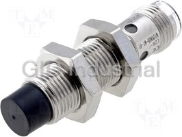
Cylindrical Proximity Sensor
E2A
Safe Mounting with Greater
Sensing Distance
• Ensures a sensing distance approximately 1.5 to 2
times larger than that of any conventional OMRON
Sensor.
Problems such as the collision of workpieces are
eliminated.
Full range of standard si zes (M8, M12, M18 and
M30; both long and short barrels)
Modular construction simplifies customization.
Please read and understand this catalog before purchasing
the products. Please consult your OMRON representative if
you have any questions or comments.
Ordering Information
Size Sensing Connection Body Thread length Output Operation mode NO Operation mode NC
distance material (overall length) configuration
M8 Shielded 2.0 mm Pre-wired Stainless 27 (40) PNP E2A-S08KS02-WP-B1 2M E2A-S08KS02-WP-B2 2M
steel
NPN E2A-S08KS02-WP-C1 2M E2A-S08KS02-WP-C2 2M
49 (62) PNP E2A-S08LS02-WP-B1 2M E2A-S08LS02-WP-B2 2M
NPN E2A-S08LS02-WP-C1 2M E2A-S08LS02-WP-C2 2M
M12 connector Stainless 27 (43) PNP E2A-S08KS02-M1-B1 E2A-S08KS02-M1-B2
steel
NPN E2A-S08KS02-M1-C1 E2A-S08KS02-M1-C2
49 (65) PNP E2A-S08LS02-M1-B1 E2A-S08LS02-M1-B2
NPN E2A-S08LS02-M1-C1 E2A-S08LS02-M1-C2
Brass 27 (43) PNP E2A-M08KS02-M1-B1 E2A-M08KS02-M1-B2
NPN E2A-M08KS02-M1-C1 E2A-M08KS02-M1-C2
49 (65) PNP E2A-M08LS02-M1-B1 E2A-M08LS02-M1-B2
NPN E2A-M08LS02-M1-C1 E2A-M08LS02-M1-C2
M8 connector (3- Stainless 27 (39) PNP E2A-S08KS02-M5-B1 E2A-S08KS02-M5-B2
pin) steel
NPN E2A-S08KS02-M5-C1 E2A-S08KS02-M5-C2
49 (61) PNP E2A-S08LS02-M5-B1 E2A-S08LS02-M5-B2
NPN E2A-S08LS02-M5-C1 E2A-S08LS02-M5-C2
Non-shielded 4.0 mm Pre-wired Stainless 27 (40) PNP E2A-S08KN04-WP-B1 2M E2A-S08KN04-WP-B2 2M
steel
NPN E2A-S08KN04-WP-C1 2M E2A-S08KN04-WP-C2 2M
49 (62) PNP E2A-S08LN04-WP-B1 2M E2A-S08LN04-WP-B2 2M
NPN E2A-S08LN04-WP-C1 2M E2A-S08LN04-WP-C2 2M
M12 connector Stainless 27 (43) PNP E2A-S08KN04-M1-B1 E2A-S08KN04-M1-B2
steel
NPN E2A-S08KN04-M1-C1 E2A-S08KN04-M1-C2
49 (65) PNP E2A-S08LN04-M1-B1 E2A-S08LN04-M1-B2
NPN E2A-S08LN04-M1-C1 E2A-S08LN04-M1-C2
Brass 27 (43) PNP E2A-M08KN04-M1-B1 E2A-M08KN04-M1-B2
NPN E2A-M08KN04-M1-C1 E2A-M08KN04-M1-C2
49 (65) PNP E2A-M08LN04-M1-B1 E2A-M08LN04-M1-B2
NPN E2A-M08LN04-M1-C1 E2A-M08LN04-M1-C2
M8 connector (3- Stainless 27 (39) PNP E2A-S08KN04-M5-B1 E2A-S08KN04-M5-B2
pin) steel
NPN E2A-S08KN04-M5-C1 E2A-S08KN04-M5-C2
49 (61) PNP E2A-S08LN04-M5-B1 E2A-S08LN04-M5-B2
NPN E2A-S08LN04-M5-C1 E2A-S08LN04-M5-C2
E2A Cylindrical Proximity Sensor 1
Size Sensing Connection Body Thread length Output Operation mode NO Operation mode NC
distance material (overall length) configuration
M12 Shielded 4.0 mm Pre-wired Brass 34 (50) PNP E2A-M12KS04-WP-B1 2M E2A-M12KS04-WP-B2 2M
NPN E2A-M12KS04-WP-C1 2M E2A-M12KS04-WP-C2 2M
56 (72) PNP E2A-M12LS04-WP-B1 2M E2A-M12LS04-WP-B2 2M
NPN E2A-M12LS04-WP-C1 2M E2A-M12LS04-WP-C2 2M
M12 connector Brass 34 (48) PNP E2A-M12KS04-M1-B1 E2A-M12KS04-M1-B2
NPN E2A-M12KS04-M1-C1 E2A-M12KS04-M1-C2
56 (70) PNP E2A-M12LS04-M1-B1 E2A-M12LS04-M1-B2
NPN E2A-M12LS04-M1-C1 E2A-M12LS04-M1-C2
Non-shielded 8.0 mm Pre-wired Brass 34 (50) PNP E2A-M12KN08-WP-B1 2M E2A-M12KN08-WP-B2 2M
NPN E2A-M12KN08-WP-C1 2M E2A-M12KN08-WP-C2 2M
56 (72) PNP E2A-M12LN08-WP-B1 2M E2A-M12LN08-WP-B2 2M
NPN E2A-M12LN08-WP-C1 2M E2A-M12LN08-WP-C2 2M
M12 connector Brass 34 (48) PNP E2A-M12KN08-M1-B1 E2A-M12KN08-M1-B2
NPN E2A-M12KN08-M1-C1 E2A-M12KN08-M1-C2
56 (70) PNP E2A-M12LN08-M1-B1 E2A-M12LN08-M1-B2
NPN E2A-M12LN08-M1-C1 E2A-M12LN08-M1-C2
M18 Shielded 8.0 mm Pre-wired Brass 39 (59) PNP E2A-M18KS08-WP-B1 2M E2A-M18KS08-WP-B2 2M
NPN E2A-M18KS08-WP-C1 2M E2A-M18KS08-WP-C2 2M
61 (81) PNP E2A-M18LS08-WP-B1 2M E2A-M18LS08-WP-B2 2M
NPN E2A-M18LS08-WP-C1 2M E2A-M18LS08-WP-C2 2M
M12 connector Brass 39 (53) PNP E2A-M18KS08-M1-B1 E2A-M18KS08-M1-B2
NPN E2A-M18KS08-M1-C1 E2A-M18KS08-M1-C2
61 (75) PNP E2A-M18LS08-M1-B1 E2A-M18LS08-M1-B2
NPN E2A-M18LS08-M1-C1 E2A-M18LS08-M1-C2
Non-shielded 16.0 mm Pre-wired Brass 39 (59) PNP E2A-M18KN16-WP-B1 2M E2A-M18KN16-WP-B2 2M
NPN E2A-M18KN16-WP-C1 2M E2A-M18KN16-WP-C2 2M
61 (81) PNP E2A-M18LN16-WP-B1 2M E2A-M18LN16-WP-B2 2M
NPN E2A-M18LN16-WP-C1 2M E2A-M18LN16-WP-C2 2M
M12 connector Brass 39 (53) PNP E2A-M18KN16-M1-B1 E2A-M18KN16-M1-B2
NPN E2A-M18KN16-M1-C1 E2A-M18KN16-M1-C2
61 (75) PNP E2A-M18LN16-M1-B1 E2A-M18LN16-M1-B2
NPN E2A-M18LN16-M1-C1 E2A-M18LN16-M1-C2
M30 Shielded 15.0 mm Pre-wired Brass 44 (64) PNP E2A-M30KS15-WP-B1 2M E2A-M30KS15-WP-B2 2M
NPN E2A-M30KS15-WP-C1 2M E2A-M30KS15-WP-C2 2M
66 (86) PNP E2A-M30LS15-WP-B1 2M E2A-M30LS15-WP-B2 2M
NPN E2A-M30LS15-WP-C1 2M E2A-M30LS15-WP-C2 2M
M12 connector Brass 44 (58) PNP E2A-M30KS15-M1-B1 E2A-M30KS15-M1-B2
NPN E2A-M30KS15-M1-C1 E2A-M30KS15-M1-C2
66 (80) PNP E2A-M30LS15-M1-B1 E2A-M30LS15-M1-B2
NPN E2A-M30LS15-M1-C1 E2A-M30LS15-M1-C2
Non-shielded 20.0 mm Pre-wired Brass 44 (64) PNP E2A-M30KN20-WP-B1 2M E2A-M30KN20-WP-B2 2M
(See note.)
NPN E2A-M30KN20-WP-C1 2M E2A-M30KN20-WP-C2 2M
30.0 mm 66 (86) PNP E2A-M30LN30-WP-B1 2M E2A-M30LN30-WP-B2 2M
NPN E2A-M30LN30-WP-C1 2M E2A-M30LN30-WP-C2 2M
20.0 mm M12 connector Brass 44 (58) PNP E2A-M30KN20-M1-B1 E2A-M30KN20-M1-B2
(See note.)
NPN E2A-M30KN20-M1-C1 E2A-M30KN20-M1-C2
30.0 mm 66 (80) PNP E2A-M30LN30-M1-B1 E2A-M30LN30-M1-B2
NPN E2A-M30LN30-M1-C1 E2A-M30LN30-M1-C2
Note: M30 non-shielded Models with double sensing distance and short barrels cannot be mounted due to the necessary separation distance from
the surrounding metal. Standard sensing models are thus available.
2 E2A Cylindrical Proximity Sensor
■ Model Number Legend
E2A@-@@@@@-@-@@-@@
1 2 3 4 5 6 7 8 9 10 11 12
Example: E2A-M12LS04-M1-B1 Standard, M12, long barrel, shielded, Sn=4 mm, M12 connector, PNP-NO
E2A-M08KN04-WP-B1 5M Standard, M8, short barrel, non-shielded, Sn=4 mm, pre-wired PVC cable, PNP-NO, cable length=5 m
1. Basic name 8. Kind of connection
E2A WP: Pre-wired, PVC
2. Sensing technology M1: M12 connector (4-pole)
Blank: Standard double distance M3: M8 connector (4-pole)
3. Housing shape and material M5: M8 connector (3-pole)
M: Cylindrical, metric threaded, brass 9. Power source and output
S: Cylindrical, metric threaded, stainless steel B: DC, 3-wire, PNP open collector
4. Housing size C: DC, 3-wire, NPN open collector
08: 8 mm D: DC, 2-wire
12: 12 mm E: DC, 3-wire, NPN voltage output
18: 18 mm F: DC, 3-wire, PNP voltage output
30: 30 mm 10.Operation mode
5. Barrel length 1: Normally open (NO)
K: Standard length 2: Normally closed (NC)
L: Long body 11.Specials (e.g., cable material, oscillating frequency)
6. Shield
S: Shielded 12.Cable length
N: Non-shielded Blank: Connector type
7. Sensing distance Numeral: Cable type
Numeral: Sensing distance: e.g. 02=2 mm, 16=16 mm
E2A Cylindrical Proximity Sensor 3
Specifications
■ DC 3-wire Models
Size M8 M12
Type Shielded Non-shielded Shielded Non-shielded
E2A-M08@S02-M1-B1 E2A-M08@N04-M1-B1 E2A-M12@S04-@@-B1 E2A-M12@N08-@@-B1
E2A-M08@S02-M1-B2 E2A-M08@N04-M1-B2 E2A-M12@S04-@@-B2 E2A-M12@N08-@@-B2
E2A-M08@S02-M1-C1 E2A-M08@N04-M1-C1 E2A-M12@S04-@@-C1 E2A-M12@N08-@@-C1
E2A-M08@S02-M1-C2 E2A-M08@N04-M1-C2 E2A-M12@S04-@@-C2 E2A-M12@N08-@@-C2
E2A-S08@S02-@@-B1 E2A-S08@N04-@@-B1
E2A-S08@S02-@@-B2 E2A-S08@N04-@@-B2
E2A-S08@S02-@@-C1 E2A-S08@N04-@@-C1
Item E2A-S08@S02-@@-C2 E2A-S08@N04-@@-C2
Sensing distance 2 mm ± 10% 4 mm ± 10% 4 mm ± 10% 8 mm ± 10%
Setting distance 0 to 1.6 mm 0 to 3.2 mm 0 to 3.2 mm 0 to 6.4 mm
Differential travel 10% max. of sensing distance
Target Ferrous metal (The sensing distance decreases with non-ferrous metal.)
Standard target (mild steel ST37) 8×8×1 mm 12×12×1 mm 12×12×1 mm 24×24×1 mm
Response frequency (See note 1.) 1,500 Hz 1,000 Hz 1,000 Hz 800 Hz
Power supply voltage 12 to 24 VDC. Ripple (p-p): 10% max.
(operating voltage range) (10 to 32 VDC)
Current consumption (DC 3-wire) 10 mA max.
Output type -B models: PNP open collector
-C models: NPN open collector
Control Load current 200 mA max. (32 VDC max.)
output (See note 2.)
Residual voltage 2 V max. (under load current of 200 mA with cable length of 2 m)
Indicator Operation indicator (Yellow LED)
Operation mode -B1/-C1 models: NO
(with sensing object approaching) -B2/-C2 models: NC
For details, refer to the timing charts.
Protection circuit Power source circuit reverse polarity protection, Output reverse polarity protection, Power source
Surge suppressor, Short-circuit protection circuit reverse polarity protection, Surge suppres-
sor, Short-circuit protection
Ambient air temperature Operating: −40°C to 70°C, Storage: −40°C to 85°C (with no icing or condensation)
Temperature influence (See note 2.) ±10% max. of sensing distance at 23°C within temperature range of −25°C to 70°C
±15% max. of sensing distance at 23°C within temperature range of −40°C to 70°C
Ambient humidity Operating: 35% to 95%, Storage: 35% to 95%
Voltage influence ±1% max. of sensing distance in rated voltage range ±15%
Insulation resistance 50 MΩ min. (at 500 VDC) between current carry parts and case
Dielectric strength 1,000 VAC at 50/60 Hz for 1 min between current carry parts and case
Vibration resistance 10 to 55 Hz, 1.5-mm double amplitude for 2 hours each in X, Y and Z directions
2 2
Shock resistance
500 m/s , 10 times each in X, Y and Z directions 1,000 m/s , 10 times each in X, Y and Z directions
Standard and listings (See note 3.) IEC60529: IP67, Degree of protection
EN60947-5-2: EMC
Connection method -WP models: Pre-wired models (Standard length: 2 m)
-M1 models: M12 4-pin connector models
-M5 models: M8 3-pin connector models
Weight Pre-wired model Approx. 65 g Approx. 85 g
(packaged)
M12 connector model M12 connector models: Approx. 20 g Approx. 35 g
M8 connector models: Approx. 15 g
Material Case Stainless steel or brass-nickel plated Brass-nickel plated
Sensing surface PBT
Cable PVC
Clamping nut Brass-nickel plated
Note 1. The response frequency is an average value. Measurement conditions are as follows: standard target, a distance of twice the standard
target distance between targets, and a setting distance of half the sensing distance.
2. When using any model at an ambient temperature between −40°C and −25°C and a power voltage between 30 and 32 VDC, use a load
current of 100 mA max.,
3. For USA and CANADA : use class 2 circuit only.
4 E2A Cylindrical Proximity Sensor
■ DC 3-wire Models
Size M18 M30
Type Shielded Non-shielded Shielded Non-shielded Non-shielded
E2A-M18@S08-@@-B1 E2A-M18@N16-@@-B1 E2A-M30@S15-@@-B1 E2A-M30KN20-@@-B1 E2A-M30LN30-@@-B1
E2A-M18@S08-@@-B2 E2A-M18@N16-@@-B2 E2A-M30@S15-@@-B2 E2A-M30KN20-@@-B2 E2A-M30LN30-@@-B2
E2A-M18@S08-@@-C1 E2A-M18@N16-@@-C1 E2A-M30@S15-@@-C1 E2A-M30KN20-@@-C1 E2A-M30LN30-@@-C1
Item E2A-M18@S08-@@-C2 E2A-M18@N16-@@-C2 E2A-M30@S15-@@-C2 E2A-M30KN20-@@-C2 E2A-M30LN30-@@-C2
Sensing distance 8 mm±10% 16 mm±10% 15 mm±10% 20 mm±10% 30 mm±10%
Setting distance 0 to 6.4 mm 0 to 12.8 mm 0 to 12 mm 0 to 16 mm 0 to 24 mm
Differential travel 10% max. of sensing distance
Target Ferrous metal (The sensing distance decreases with non-ferrous metal.)
Standard target 24×24×1 mm 48×48×1 mm 45×45×1 mm 60×60×1 mm 90×90×1 mm
(mild steel ST37)
Response frequency 500 Hz 400 Hz 250 Hz 100 Hz 100 Hz
(See note 1.)
Power supply voltage 12 to 24 VDC. Ripple (p-p): 10% max.
(operating voltage range) (10 to 32 VDC)
Current consumption (DC 10 mA max.
3-wire)
Output type -B models: PNP open collector
-C models: NPN open collector
Control Load current (See 200 mA max. (32 VDC max.)
output note 2.)
Residual voltage 2 V max. (under load current of 200 mA with cable length of 2 m)
Indicator Operation indicator (Yellow LED)
Operation mode -B1/-C1 models: NO
(with sensing object ap- -B2/-C2 models: NC
proaching) For details, refer to the timing charts.
Protection circuit Output reverse polarity protection, Power source circuit reverse polarity protection, Surge suppressor, Short-circuit
protection
Ambient air temperature Operating: −40°C to 70°C, Storage: −40°C to 85°C (with no icing or condensation)
Temperature influence (See ±10% max. of sensing distance at 23°C within temperature range of −25°C to 70°C
note 2.) ±15% max. of sensing distance at 23°C within temperature range of −40°C to 70°C
Ambient humidity Operating: 35% to 95%, Storage: 35% to 95%
Voltage influence ±1% max. of sensing distance in rated voltage range ±15%
Insulation resistance 50 MΩ min. (at 500 VDC) between current carry parts and case
Dielectric strength 1,000 VAC at 50/60 Hz for 1 min between current carry parts and case
Vibration resistance 10 to 55 Hz, 1.5-mm double amplitude for 2 hours each in X, Y and Z directions
2
Shock resistance
1,000 m/s , 10 times each in X, Y and Z directions
Standard and listings IEC60529: IP67, Degree of protection
(See note 3.) EN60947-5-2: EMC
Connection method -WP models: Pre-wired models (Standard length: 2 m)
-M1 models: M12 4-pin connector models
-M5 models: M8 3-pin connector models
Weight Pre-wired model Approx. 160 g Approx. 280 g Approx. 280 g Approx. 370 g
(pack-
M12 connector Approx. 70 g Approx. 200 g Approx. 200 g Approx. 260 g
aged)
model
Material Case Brass-nickel plated
Sensing surface PBT
Cable PVC
Clamping nut Brass-nickel plated
Note 1. The response frequency is an average value. Measurement conditions are as follows: standard target, a distance of twice the standard
target distance between targets, and a setting distance of half the sensing distance.
2. When using any model at an ambient temperature between -40°C and -25°C and a power voltage between 30 and 32 VDC, use a load
current of 100 mA max.
3. For USA and CANADA : use class 2 circuit only.
E2A Cylindrical Proximity Sensor 5
Engineering Data
Operating Range (Typical)
Shielded Models Non-shielded Models
35
18
E2A-M30LN30
E2A-M30@S15
16
30
14
Y
25
X
Y
12
E2A-M30KN20
X
E2A-M18@S08
20
10
E2A-M18@N16
8
15
E2A-M12@S04
E2A-M12@N08
6
E2A-S08@S02/
10
E2A-M08@S02
E2A-S08@N04/
4
E2A-M08@N04
5
2
0
0
−50 −40 −30 −20 −10 0 10 20 30 40 50
−30 −20 −10 0 10 20 30
Distance Y (mm)
Distance Y (mm)
Influence of Sensing Object Size and Materials
Shielded Models
E2A-S08@S02/M08@S02 E2A-M12@S04
E2A-M18@S08
8.0
2.5 5.0
@d
@d
Iron
t = 1 mm t = 1 mm
7.0
X X
Iron
Iron
2.0 4.0
6.0
Stainless steel (SUS303)
Stainless steel
Stainless steel (SUS303) (SUS303)
5.0
1.5 3.0
Brass
Brass
4.0
Brass
Aluminum
Aluminum
1.0
Aluminum 2.0
3.0
Copper
Copper
Copper
@d
2.0
t = 1 mm
0.5 X
1.0
1.0
0 510 15 20 25 30 35 0 10 20 30 40 50 60
0 5 10 15 20 25
Side length of sensing object d (mm) Side length of sensing object d (mm) Side length of sensing object d (mm)
E2A-M30@S15
20
@d
t = 1 mm
X
16
Iron
12
Stainless steel (SUS303)
8
Brass
Aluminum
Copper
4
0 10 20 30 40 50 60 70 80
Side length of sensing object d (mm)
6 E2A Cylindrical Proximity Sensor
Sensing distance X (mm) Sensing distance X (mm)
Sensing distance X (mm)
Sensing distance X (mm)
Sensing distance X (mm)
Sensing distance X (mm)
Non-shielded Models
E2A-S08@N04/M08@N04 E2A-M12@N08 E2A-M18@N16
20
10
5.0
@d
@d @d
t = 1 mm
t = 1 mm t = 1 mm
X
X X
Iron
Iron
Iron
4.0 8 16
Stainless steel (SUS303)
3.0 6 12
Stainless steel (SUS303)
Stainless steel (SUS303)
Brass
4 8 Brass
2.0
Brass
Aluminum
Aluminum
Aluminum
Copper Copper
Copper
2 4
1.0
0 10 20 30 40 50 0 20 40 60 80
0 10 20 30 40 50
Side length of sensing object d (mm) Side length of sensing object d (mm) Side length of sensing object d (mm)
E2A-M30LN30
E2A-M30KN20
35
25
@d
@d
Iron
t = 1 mm
t = 1 mm
X 30
X
Iron
20
25
Stainless steel (SUS303)
15
20
Stainless steel (SUS303)
Brass
15
10
Aluminum
Brass
Copper
Aluminum
10
Copper
5
5
0 20 40 60 80 100
0 20 40 60 80 100
Side length of sensing object d (mm)
Side length of sensing object d (mm)
E2A Cylindrical Proximity Sensor 7
Sensing distance X (mm) Sensing distance X (mm)
Sensing distance X (mm)
Sensing distance X (mm)
Sensing distance X (mm)
Rated
Rated
sensing sensing
distance distance
Proximity
Sensor
Proximity
Sensor
Operation
■ PNP Output
Operation mode Model Timing chart Output circuit
NO E2A-@-@-B1
Non-sensing zone Sensing zone
Brown
+V
Sensing
object
Proximity
Black
Sensor
100 0
(%)
main
circuits (See note 1.)
Load
Blue
ON
0 V
Yellow indicator
OFF
ON
Note 1: With M8 connector models, there is no output
Control output
reverse polarity protection diode.
OFF
M12 Connector
M8 Connector
Pin Arrangement Pin Arrangement
(See note 2.)
4
1
1 3
2 4
3
Note 2: Terminal 2 of the M12 connector is not used.
NC E2A-@-@-B2
Non-sensing zone Sensing zone
Brown
+V
Sensing
object
Black
Proximity
(M8 connector: )
Sensor
(%) 100 0
main
(See note 1.)
circuits
Load
Blue
ON 0 V
Yellow indicator
OFF
Note 1: With M8 connector models, there is no output
ON
Control output reverse polarity protection diode.
OFF
M12 Connector
M8 Connector
Pin Arrangement Pin Arrangement
(See note 2.)
4
1
3
1
2 4
3
Note 2: Terminal 4 of the M12 connector is not used.
8 E2A Cylindrical Proximity Sensor
Rated
Rated
sensing sensing
distance distance
Proximity
Sensor
Proximity
Sensor
■ NPN Output
Operation mode Model Timing chart Output circuit
NO E2A-@-@-C1
Non-sensing zone Sensing zone
Brown
+V
Sensing
object
Load
Proximity
(See note 1.)
Black
Sensor
(%) 100 0
main
circuits
Blue
0 V
ON
Yellow indicator
OFF
ON
Note 1: With M8 connector models, there is no output
Control output
OFF reverse polarity protection diode.
M12 Connector
M8 Connector
Pin Arrangement Pin Arrangement
(See note 2.)
4
1
1 3
2 4
3
Note 2: Terminal 2 of the M12 connector is not used.
NC E2A-@-@-C2
Non-sensing zone Sensing zone
Brown
+V
Sensing
object
Load
Proximity
(See note 1.)
Black
Sensor
(%) 100 0
main
(M8 connector: )
circuits
Blue
ON 0 V
Yellow indicator
OFF
ON
Note 1: With M8 connector models, there is no output
Control output
reverse polarity protection diode.
OFF
M12 Connector
M8 Connector
Pin Arrangement
Pin Arrangement
(See note 2.)
4
1
1 3
2 4
3
Note 2: Terminal 4 of the M12 connector is not used.
E2A Cylindrical Proximity Sensor 9
Dimensions
Note:All units are in millimeters unless otherwise indicated.
Pre-wired Models (Shielded) Pre-wired Models (Non-shielded)
E2A-S08KS02-WP-@@
E2A-S08KN04-WP-@@
40
40
27
27
13 6 3 5
3 5
13
6 dia.
(See note 1.)
(See note 1.) Indicator (See note 2.)
Indicator (See note 2.) M8×1
M8×1 Two, clamping nuts
Two, clamping nuts
Note 1. 4-dia. vinyl-insulated round cable with 3 conductors (conductor cross section: Note 1. 4-dia. vinyl-insulated round cable with 3 conductors (conductor cross section:
2 2
0.3 mm ; insulator diameter: 1.3 mm); standard length: 2 m 0.3 mm ; insulator diameter: 1.3 mm); standard length: 2 m
2. Operation indicator (yellow) 2. Operation indicator (yellow)
E2A-M12KS04-WP-@@
E2A-M12KN08-WP-@@
50.3
50.3
34 34
17 17 7 47
4 7
9.4 dia.
(See note 1.)
(See note 1.)
Indicator (See note 2.)
Indicator (See note 2.)
M12×1
M12×1
Two, clamping nuts
Two, clamping nuts
Note 1. 4-dia. vinyl-insulated round cable with 3 conductors (conductor cross section:
Note 1. 4-dia. vinyl-insulated round cable with 3 conductors (conductor cross section:
2
0.3 mm ; insulator diameter: 1.3 mm); standard length: 2 m
2
0.3 mm ; insulator diameter: 1.3 mm); standard length: 2 m
2. Operation indicator (yellow)
2. Operation indicator (yellow)
E2A-M18KS08-WP-@@
E2A-M18KN16-WP-@@
59.5
59.5
39
39
24 10 4 10
24 410
15.3 dia.
(See note 1.)
(See note 1.)
Indicator (See note 2.)
Indicator (See note 2.)
M18×1
M18×1
Two, clamping nuts
Two, clamping nuts
Note 1. 4-dia. vinyl-insulated round cable with 3 conductors (conductor cross section:
Note 1. 4-dia. vinyl-insulated round cable with 3 conductors (conductor cross section:
2
0.3 mm ; insulator diameter: 1.3 mm); standard length: 2 m
2
0.3 mm ; insulator diameter: 1.3 mm); standard length: 2 m
2. Operation indicator (yellow)
2. Operation indicator (yellow)
E2A-M30KS15-WP-@@ E2A-M30KN20-WP-@@
64.5
64.5
44
44
15
36 5 10
5 10
36
26.6 dia.
(See note 1.)
(See note 1.)
Indicator (See note 2.)
Indicator (See note 2.)
M30×1.5
M30×1.5
Two, clamping nuts
Two, clamping nuts
Note 1. 4-dia. vinyl-insulated round cable with 3 conductors (conductor cross section:
2
0.3 mm ; insulator diameter: 1.3 mm); standard length: 2 m
Note 1. 4-dia. vinyl-insulated round cable with 3 conductors (conductor cross section: 2. Operation indicator (yellow)
2
0.3 mm ; insulator diameter: 1.3 mm); standard length: 2 m
2. Operation indicator (yellow)
10 E2A Cylindrical Proximity Sensor
E2A-S08LS02-WP-@@
E2A-S08LN04-WP-@@
62
62
49
49
3 5
13 6
13 3 5
6 dia.
(See note 1.)
(See note 1.)
Indicator (See note 2.)
M8×1
Indicator (See note 2.)
M8×1
Two, clamping nuts
Two, clamping nuts
Note 1. 4-dia. vinyl-insulated round cable with 3 conductors (conductor cross section: Note 1. 4-dia. vinyl-insulated round cable with 3 conductors (conductor cross section:
2 2
0.3 mm ; insulator diameter: 1.3 mm); standard length: 2 m 0.3 mm ; insulator diameter: 1.3 mm); standard length: 2 m
2. Operation indicator (yellow) 2. Operation indicator (yellow)
E2A-M12LN08-WP-@@
E2A-M12LS04-WP-@@
72.3
72.3
56
17 56 17
4
7 4 7
7
9.4 dia.
(See note 1.)
(See note 1.)
Indicator (See note 2.)
Indicator (See note 2.)
M12×1
M12×1
Two, clamping nuts
Two, clamping nuts
Note 1. 4-dia. vinyl-insulated round cable with 3 conductors (conductor cross section:
Note 1. 4-dia. vinyl-insulated round cable with 3 conductors (conductor cross section:
2
0.3 mm ; insulator diameter: 1.3 mm); standard length: 2 m
2
0.3 mm ; insulator diameter: 1.3 mm); standard length: 2 m
2. Operation indicator (yellow)
2. Operation indicator (yellow)
E2A-M18LN16-WP-@@
E2A-M18LS08-WP-@@
81.5
61
81.5
4
24 10
10
61
24 10
4
15.3 dia.
(See note 1.)
(See note 1.)
Indicator (See note 2.)
Indicator (See note 2.)
M18×1
M18×1 Two, clamping nuts
Two, clamping nuts
Note 1. 4-dia. vinyl-insulated round cable with 3 conductors (conductor cross section:
2
0.3 mm ; insulator diameter: 1.3 mm); standard length: 2 m
Note 1. 4-dia. vinyl-insulated round cable with 3 conductors (conductor cross section:
2 2. Operation indicator (yellow)
0.3 mm ; insulator diameter: 1.3 mm); standard length: 2 m
2. Operation indicator (yellow)
E2A-M30LN30-WP-@@
E2A-M30LS15-WP-@@
86.5
86.5
66
66
36 15 5
10
36 5
10
26.6 dia.
(See note 1.)
(See note 1.) Indicator (See note 2.)
Indicator (See note 2.)
M30×1.5
Two, clamping nuts
M30×1.5
Two, clamping nuts
Note 1. 4-dia. vinyl-insulated round cable with 3 conductors (conductor cross section:
2
Note 1. 4-dia. vinyl-insulated round cable with 3 conductors (conductor cross section: 0.3 mm ; insulator diameter: 1.3 mm); standard length: 2 m
2
0.3 mm ; insulator diameter: 1.3 mm); standard length: 2 m
2. Operation indicator (yellow)
2. Operation indicator (yellow)
Mounting Hole Cutout Dimensions
External diameter
Dimension F (mm)
of Proximity Sensor
+0.5
M8 8.5 dia.
0
+0.5
M12
12.5 dia. 0
+0.5
M18 18.5 dia. 0
F
+0.5
M30
30.5 dia. 0
E2A Cylindrical Proximity Sensor 11
M12 Connector Models (Shielded) M12 Connector Models (Non-shielded)
E2A-S08KN04-M1-@@
E2A-S08KS02-M1-@@
E2A-M08KN04-M1-@@
E2A-M08KS02-M1-@@
43
43
27
27
M12×1
13 5
3 6 3
13 5
M12×1
6 dia.
Indicator (See note.)
Indicator (See note.) M8×1
M8×1
Two, clamping nuts Two, clamping nuts
Note: Operation indicator (yellow LED, 4×90°)
Note: Operation indicator (yellow LED, 4×90°)
E2A-M12KS04-M1-@@ E2A-M12KN08-M1-@@
48
48
34 34
17 7 17
4 4
M12×1
M12×1
77
9.4 dia.
Indicator (See note.) Indicator (See note.)
M12×1
M12×1
Two, clamping nuts Two, clamping nuts
Note: Operation indicator (yellow LED, 4×90°)
Note: Operation indicator (yellow LED, 4×90°)
E2A-M18KS08-M1-@@ E2A-M18KN16-M1-@@
53
53
39
39
10
24 4
10
24
4 10
M12×1
M12×1
15.3 dia.
Indicator (See note.)
Indicator (See note.)
M18×1
Two, clamping nuts M18×1
Two, clamping nuts
Note: Operation indicator (yellow LED, 4×90°)
Note: Operation indicator (yellow LED, 4×90°)
E2A-M30KS15-M1-@@
E2A-M30KN20-M1-@@
58
58
44
44
15 5 10
36
36 10
5
M12×1
M12×1
26.6 dia.
Indicator (See note.)
Indicator (See note.)
M30×1.5
Two, clamping nuts
M30×1.5
Two, clamping nuts
Note: Operation indicator (yellow LED, 4×90°)
Note: Operation indicator (yellow LED, 4×90°)
12 E2A Cylindrical Proximity Sensor
E2A-S08LN04-M1-@@
E2A-S08LS02-M1-@@
E2A-M08LN04-M1-@@
65
E2A-M08LS02-M1-@@ 65
49
49
M12×1
13 5
6 3
13 3 5
M12×1
6 dia.
Indicator (See note.)
Indicator (See note.) M8×1
M8×1
Two, clamping nuts
Note: Operation indicator (yellow LED, 4×90°)
Note: Operation indicator (yellow LED, 4×90°)
70
E2A-M12LS04-M1-@@
E2A-M12LN08-M1-@@
70
56
56
4
17
7
7
4
17
M12×1
7
M12×1
9.4 dia.
Indicator (See note.)
Indicator (See note.)
M12×1
M12×1
Two, clamping nuts
Two, clamping nuts
Note: Operation indicator (yellow LED, 4×90°)
Note: Operation indicator (yellow LED, 4×90°)
75
75
E2A-M18LS08-M1-@@
E2A-M18LN16-M1-@@
61
61
10
24 10
24
4 4
10
M12×1
M12×1
15.3 dia.
Indicator (See note.)
Indicator (See note.)
M18×1
M18×1
Two, clamping nuts Two, clamping nuts
Note: Operation indicator (yellow LED, 4×90°) Note: Operation indicator (yellow LED, 4×90°)
80
E2A-M30LN30-M1-@@
66
E2A-M30LS15-M1-@@
80
10
15 5
36
66
10
36 5
M12×1
26.6 dia.
Indicator (See note.)
Indicator (See note.)
M30×1.5
Two, clamping nuts
M30×1.5
Two, clamping nuts
Note: Operation indicator (yellow LED, 4×90°)
Note: Operation indicator (yellow LED, 4×90°)
M8 Connector Models (Shielded) M8 Connector Models (Non-shielded)
E2A-S08KS02-M5-@@
E2A-S08KN04-M5-@@
39
39
27
27
M8×1
5
13 3 5 13 6 3
M8×1
6 dia.
M8×1
M8×1
Two, clamping nuts
Two, clamping nuts
Note: Operation indicator (yellow LED, 4×90°)
Note: Operation indicator (yellow LED, 4×90°)
E2A-S08LS02-M5-@@
E2A-S08LN04-M5-@@
61
61
49
49
M8×1
6 3 5
13 3 5 13
M8×1
6 dia.
M8×1
M8×1
Note: Operation indicator (yellow LED, 4×90°)
Note: Operation indicator (yellow LED, 4×90°)
E2A Cylindrical Proximity Sensor 13
Precautions
Wiring
■ Safety Precautions
Be sure to wire the E2A and load correctly, otherwise it may be dam-
aged.
Power Supply
Do not impose an excessive voltage on the E2A, otherwise it may be
Connection with No Load
damaged. Do not impose AC current (100 to 240 VAC) on any DC
model, otherwise it may be damaged.
Be sure to insert loads when wiring. Make sure to connect a proper
load to the E2A in operation, otherwise it may damage internal ele-
ments.
Load Short-circuit
Do not expose the product to flammable or explo-
Do not short-circuit the load, or the E2A may be damaged.
sive gases.
The E2A’s short-circuit protection function will be valid if the polarity
of the supply voltage imposed is correct and within the rated voltage
Do not disassemble, repair, or modify the product.
range.
■ Correct Use
Power OFF
Designing
The Proximity Sensor may output a pulse signal when it is turned
OFF. Therefore, it is recommended that the load be turned OFF
before turning OFF the Proximity Sensor.
Power Reset Time
The Proximity Sensor is ready to operate within 100 ms after power
Power Supply Transformer
is supplied. If power supplies are connected to the Proximity Sensor
When using a DC power supply, make sure that the DC power sup-
and load respectively, be sure to supply power to the Proximity Sen-
ply has an insulated transformer. Do not use a DC power supply with
sor before supplying power to the load.
an auto-transformer.
Effects of Surrounding Metal
Mutual Interference
When mounting the E2A within a metal panel, ensure that the clear-
ances given in the following table are maintained. When installing two or more Sensors face-to-face or side-by-side,
ensure that the minimum distances given in the following table are
maintained.
l
n
d dia.
m
D
m l
(Unit: mm)
(Unit: mm)
Type Dimension M8 M12 M18 M30
Type Dimension M8 M12 M18 M30
Short Long
Short Long
barrel barrel
barrel barrel
Shielded l 000 0
Shielded A 20 30 60 110
(See note (See note 2.)
1.)
B 15 203570
m 4.5 12 24 45
Non- A 80 120 200 300 300
shielded
d --- --- 27 45
B 60 100 120 200 300
D 001.5 4
n 121827 45
Non- l 12 15 22 30 40
shielded
m 8 20 48 70 90
d 244070 90 120
D 121522 30 40
n 244070 90 120
Note 1. In the case of using the supplied nuts.
If true flash mounting is necessary, apply a free zone of
1.5 mm.
2. In the case of using the supplied nuts.
If true flush mounting is necessary, apply a free zone of
4 mm.
14 E2A Cylindrical Proximity Sensor
Wiring Maintenance and Inspection
Periodically perform the following checks to ensure stable operation
High-tension Lines
of the Proximity Sensor over a long period of time.
Wiring through Metal Conduit:
1. Check for mounting position, dislocation, looseness, or distortion
If there is a power or high-tension line near the cable of the Proximity
of the Proximity Sensor and sensing objects.
Sensor, wire the cable through an independent metal conduit to pre-
2. Check for loose wiring and connections, improper contacts, and
vent against Proximity Sensor damage or malfunctioning.
line breakage.
3. Check for attachment or accumulation of metal powder or dust.
Cable Extension
4. Check for abnormal temperature conditions and other environ-
mental conditions.
Standard cable length is less than 200 m.
5. Check for proper lighting of indicators (for models with a set indi-
The tractive force is 50 N.
cator.)
Never disassemble or repair the Sensor.
Mounting
The Proximity Sensor must not be subjected to excessive shock with
Environment
a hammer when it is installed, otherwise the Proximity Sensor may
be damaged or lose its water-resistivity.
Water Resistivity
Do not tighten the nut with excessive force. A washer must be used
with the nut. Do not use the Proximity Sensor underwater, outdoors, or in the rain.
Operating Environment
Be sure to use the Proximity Sensor within its operating ambient
temperature range and do not use the Proximity Sensor outdoors so
that its reliability and life expectancy can be maintained. Although
the Proximity Sensor is water resistive, a cover to protect the Prox-
imity Sensor from water or water-soluble machining oil is recom-
Type Torque
mended so that its reliability and life expectancy can be maintained.
M8 Stainless steel type 9 N·m
Do not use the Proximity Sensor in an environment with chemical
Brass type 4 N·m
gas (e.g., strong alkaline or acid gasses including nitric, chromic,
and concentrated sulfuric acid gases).
M12 30 N·m
M18 70 N·m
Inrush Current
M30 180 N·m
A load that has a large inrush current (e.g., a lamp or motor) will
damage the Proximity Sensor, in which case connect the load to the
Proximity Sensor through a relay.
E2A Cylindrical Proximity Sensor 15
Warranties, Limitations of Liability
■ WARRANTY ■ LIMITATIONS OF LIABILITY
OMRON’s exclusive warranty is that the products are free OMRON SHALL NOT BE RESPONSIBLE FOR SPECIAL,
from defects in materials and workmanship for a period of INDIRECT, OR CONSEQUENTIAL DAMAGES, LOSS OF
one year (or other period if specified) from date of sale by PROFITS OR COMMERCIAL LOSS IN ANY WAY
OMRON. CONNECTED WITH THE PRODUCTS, WHETHER SUCH
CLAIM IS BASED ON CONTRACT, WARRANTY,
OMRON MAKES NO WARRANTY OR REPRESENTATION,
NEGLIGENCE, OR STRICT LIABILITY.
EXPRESS OR IMPLIED, REGARDING NON-
INFRINGEMENT, MERCHANTABILITY, OR FITNESS FOR In no event shall responsibility of OMRON for any act exceed
PARTICULAR PURPOSE OF THE PRODUCTS. ANY the individual price of the product on which liability is
asserted.
BUYER OR USER ACKNOWLEDGES THAT THE BUYER
OR USER ALONE HAS DETERMINED THAT THE
IN NO EVENT SHALL OMRON BE RESPONSIBLE FOR
PRODUCTS WILL SUITABLY MEET THE REQUIREMENTS
WARRANTY, REPAIR, OR OTHER CLAIMS REGARDING
OF THEIR INTENDED USE. OMRON DISCLAIMS ALL
THE PRODUCTS UNLESS OMRON’S ANALYSIS
OTHER WARRANTIES, EXPRESS OR IMPLIED.
CONFIRMS THAT THE PRODUCTS WERE PROPERLY
HANDLED, STORED, INSTALLED, AND MAINTAINED AND
NOT SUBJECT TO CONTAMINATION, ABUSE, MISUSE,
OR INAPPROPRIATE MODIFICATION OR REPAIR.
Application Considerations
■ SUITABILITY FOR USE
OMRON shall not be responsible for conformity with any Know and observe all prohibitions of use applicable to this
standards, codes, or regulations that apply to the product.
combination of products in the customer’s application or use
NEVER USE THE PRODUCTS FOR AN APPLICATION
of the products.
INVOLVING SERIOUS RISK TO LIFE OR PROPERTY
Take all necessary steps to determine the suitability of the WITHOUT ENSURING THAT THE SYSTEM AS A WHOLE
product for the systems, machines, and equipment with HAS BEEN DESIGNED TO ADDRESS THE RISKS, AND
which it will be used. THAT THE OMRON PRODUCT IS PROPERLY RATED AND
INSTALLED FOR THE INTENDED USE WITHIN THE
OVERALL EQUIPMENT OR SYSTEM.
Disclaimers
■ CHANGE IN SPECIFICATIONS ■ DIMENSIONS AND WEIGHTS
Product specifications and accessories may be changed at Dimensions and weights are nominal and are not to be used
any time based on improvements and other reasons. Consult for manufacturing purposes, even when tolerances are
with your OMRON representative at any time to confirm shown.
actual specifications of purchased product.
ALL DIMENSIONS SHOWN ARE IN MILLIMETERS.
To convert millimeters into inches, multiply by 0.03937. To convert grams into ounces, multiply by 0.03527.
Cat. No. D100-E1-01B
In the interest of product improvement, specifications are subject to change without notice.
OMRON Corporation
Industrial Automation Company
Sensing Devices Division H.Q.
Industrial Sensors Division
Shiokoji Horikawa, Shimogyo-ku,
Kyoto, 600-8530 Japan
Tel: (81)75-344-7022/Fax: (81)75-344-7107
16
Cat. No. D100-E1-01B
2008.7
In the interest of product improvement, specifications are subject to change without notice.
OMRON Corporation
Industrial Automation Company
http://www.ia.omron.com/
(c)Copyright OMRON Corporation 2008 All Rights Reserved.


 Manufacturers


What they say about us
FANTASTIC RESOURCE
One of our top priorities is maintaining our business with precision, and we are constantly looking for affiliates that can help us achieve our goal. With the aid of GID Industrial, our obsolete product management has never been more efficient. They have been a great resource to our company, and have quickly become a go-to supplier on our list!
Bucher Emhart Glass
EXCELLENT SERVICE
With our strict fundamentals and high expectations, we were surprised when we came across GID Industrial and their competitive pricing. When we approached them with our issue, they were incredibly confident in being able to provide us with a seamless solution at the best price for us. GID Industrial quickly understood our needs and provided us with excellent service, as well as fully tested product to ensure what we received would be the right fit for our company.
Fuji
HARD TO FIND A BETTER PROVIDER
Our company provides services to aid in the manufacture of technological products, such as semiconductors and flat panel displays, and often searching for distributors of obsolete product we require can waste time and money. Finding GID Industrial proved to be a great asset to our company, with cost effective solutions and superior knowledge on all of their materials, it’d be hard to find a better provider of obsolete or hard to find products.
Applied Materials
CONSISTENTLY DELIVERS QUALITY SOLUTIONS
Over the years, the equipment used in our company becomes discontinued, but they’re still of great use to us and our customers. Once these products are no longer available through the manufacturer, finding a reliable, quick supplier is a necessity, and luckily for us, GID Industrial has provided the most trustworthy, quality solutions to our obsolete component needs.
Nidec Vamco
TERRIFIC RESOURCE
This company has been a terrific help to us (I work for Trican Well Service) in sourcing the Micron Ram Memory we needed for our Siemens computers. Great service! And great pricing! I know when the product is shipping and when it will arrive, all the way through the ordering process.
Trican Well Service
GO TO SOURCE
When I can't find an obsolete part, I first call GID and they'll come up with my parts every time. Great customer service and follow up as well. Scott emails me from time to time to touch base and see if we're having trouble finding something.....which is often with our 25 yr old equipment.
ConAgra Foods