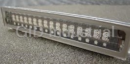
Vacuum Fluorescent Display
Module
Specification
Model: GU140X16J-7003
Specification No: DS-950-0001-01
Date Of Issue: November 12, 2002
Revision: June 11, 2004
Published by
NORITAKE ITRON CORP. / Japan
http://www.noritake-itron.jp
This specification is subject to change without prior notice.
GU140X16J-7003
Index.
1 General Description...........................................................................................................................................................3
1.1 Scope ............................................................................................................................................................................ 3
1.2 Construction ................................................................................................................................................................. 3
1.3 Outline ........................................................................................................................................................................... 3
1.4 Block Diagram.............................................................................................................................................................. 3
2 Electrical specification......................................................................................................................................................4
2.1 Absolute Maximum Ratings ....................................................................................................................................... 4
2.2 Electrical ratings........................................................................................................................................................... 4
2.3 Electrical Characteristics ............................................................................................................................................ 4
3 Optical Specifications........................................................................................................................................................5
4 Environmental Specifications..........................................................................................................................................5
5 Interface................................................................................................................................................................................5
5.1 Type of interface .......................................................................................................................................................... 5
5.2 Serial interface ............................................................................................................................................................. 5
5.2.1 Basic function ....................................................................................................................................................... 5
5.2.2 Asynchronous serial interface timing.................................................................................................................... 5
5.2.3 Synchronous serial interface timing ...................................................................................................................... 6
5.3 Reset timing.................................................................................................................................................................. 6
6 Display specification.........................................................................................................................................................7
6.1 Displayable image types............................................................................................................................................. 7
6.1.1 Graphic display ..................................................................................................................................................... 7
6.1.2 Character display................................................................................................................................................... 7
6.2 Display memory ........................................................................................................................................................... 7
6.3 Window.......................................................................................................................................................................... 8
6.3.1 Base-Window........................................................................................................................................................ 8
6.3.2 User-Window ........................................................................................................................................................ 8
6.4 Write screen mode for “Base Window” ................................................................................................................... 9
6.4.1 Display screen mode (Scanning)........................................................................................................................... 9
6.4.2 All screen mode (Scanning) .................................................................................................................................. 9
6.5 Character display format........................................................................................................................................... 10
7 Function..............................................................................................................................................................................11
7.1 Commands ................................................................................................................................................................. 11
7.1.1 Character display................................................................................................................................................. 11
7.1.2 BS (Back Space).................................................................................................................................................. 12
7.1.3 HT (Horizontal Tab) – 1 character to right.......................................................................................................... 12
7.1.4 LF (Line Feed) .................................................................................................................................................... 13
7.1.5 HOM (Home Position)........................................................................................................................................ 14
7.1.6 CR (Carriage Return) .......................................................................................................................................... 14
7.1.7 US $ xL xH yL yH (Cursor Set)........................................................................................................................ 14
7.1.8 CLR (Display Clear)........................................................................................................................................... 14
7.1.9 US C n (Cursor ON/OFF) ................................................................................................................................... 14
7.1.10 ESC@ (Initialize Display).................................................................................................................................. 14
7.1.11 ESC % n (Specify Download Register) ............................................................................................................... 15
7.1.12 ESC & a c1 c2 [x1 d1...d(a×x1)]...[xk d1...d(a×xk)] (Download character definition)................................... 15
7.1.13 ESC ? a c (Delete downloaded character) .......................................................................................................... 16
7.1.14 ESC R n (Specifies International font set)........................................................................................................... 16
7.1.15 ESC t n (Specifies character code type) .............................................................................................................. 16
7.1.16 US MD1 (Over-write mode)................................................................................................................................16
7.1.17 US MD2 (Vertical scroll mode)........................................................................................................................... 17
7.1.18 US MD3 (Horizontal scroll mode)..................................................................................................................... 17
7.1.19 US s n (Horizontal scroll speed) ....................................................................................................................... 17
7.1.20 US r n (Specifies or cancels reverse display) ..................................................................................................... 17
7.1.21 US w n (Specifies write mixture display mode).................................................................................................. 18
7.1.22 US X n (Brightness level setting) ....................................................................................................................... 18
- 1 -
GU140X16J-7003
7.1.23 US ( a n [parameter] (Display action command group)...................................................................................... 18
7.1.24 US ( a n t (Wait) ...................................................................................................................... 18
7.1.25 US ( a n wL wH cL cH s (Scroll display action)..................................................................... 19
7.1.26 US ( a n p t1 t2 c (Display Blink) ............................................................................................ 19
7.1.27 US ( a n p (Screen saver) ........................................................................................................ 20
7.1.28 US ( f n [parameter] (Bit image display group)................................................................................................. 20
7.1.29 US ( f n xL xH yL yH g d(1)...d(k) .......................................................................................... 20
7.1.30 US ( g n [parameter] (Font command group).................................................................................................... 21
7.1.31 US ( g n w (Character display width).................................................................................... 21
7.1.32 US ( g n x y (Font magnified display).................................................................................... 22
7.1.33 US ( w n [parameter] (Window command group).............................................................................................. 22
7.1.34 US ( w n a (Current Window select)........................................................................................ 23
7.1.35 US ( w n a b[xPL xPH yPL yPH xSL xSH ySL ySH]............................................................ 23
7.1.36 US ( w n a (Write screen mode select (see sect. 6.3)............................................................... 24
7.1.37 WINx (Short-Cut Current Window Select) ......................................................................................................... 24
7.2 Bit image data format ................................................................................................................................................ 25
8 Setup....................................................................................................................................................................................26
8.1 Jumper ........................................................................................................................................................................ 26
8.1.1 Baud rate select (Applying for Asynchronous serial interface)........................................................................... 26
8.1.2 Serial interface select .......................................................................................................................................... 26
9 Connector...........................................................................................................................................................................26
9.1 Serial interface connector (Six through holes)....................................................................................................... 26
9.1.1 Case of Asynchronous serial interface is selected. .............................................................................................. 26
9.1.2 Case of Synchronous serial interface is selected. ................................................................................................ 26
10 Firmware Version Notation........................................................................................................................................27
11 Outline Drawing............................................................................................................................................................28
Notice for the Cautious Handling VFD Modules................................................................................................................29
Revision Note..............................................................................................................................................................................30
- 2 -
GU140X16J-7003
1 General Description
1.1 Scope
This specification covers the operation and operating requirements of the vacuum fluorescent
graphic display module GU140X16J-7003.
1.2 Construction
The module consists of a 140 x 16dot graphic BD-VFD, refresh RAM, character generator, DC/DC
converter, display controller, and all necessary control logic. The module can simultaneously
display graphic patterns and/or characters on the screen.
1.3 Outline
Power supply: + 5 V only
DC
Interface: Serial interface (C-MOS Synchronous or Asynchronous, Selectable)
Function: Character display, 5x7, Attribution
(5x7Character font, refer to spec. of DS-898-0002-xx)
Graphic display
Control command
Character download function
Screen saver function
Applied reliability spec: TT-99-3102
Applied production spec:TT-98-3413
1.4 Block Diagram
Controller BD-VFD
Serial I/F
Connecter
Jumper
VDD2
VCC
DC/DC
EF1
Converter
EF2
GND
- 3 -
GU140X16J-7003
2 Electrical specification
2.1 Absolute Maximum Ratings
Parameter SymbolMin.Typ.Max. Unit
Power Supply Voltage VCC -0.3 - +6.0 VDC
Logic Supply Voltage
VIN -0.3 - Vcc+0.3 VDC
SIN, SCK, /RESET
2.2 Electrical ratings
Parameter SymbolMin. Typ. Max. Unit
Power Supply Voltage VCC 4.75 5.0 5.25 VDC
All driving voltage for the VFD is converted from the DC/DC converter on board.
2.3 Electrical Characteristics
Measuring Conditions: Ambient temperature = 25degrees C, VCC =5.0VDC
Parameter SymbolMin. Typ. Max. Unit Condition Note
“L” Level Logic Input Current
IIL -0.6 mA VIN=0V
SIN, SCK, /RESET
“H” Level Logic Input Current
IIH - - 1.0 uADC VIN=5V -
SIN, SCK, /RESET
"H" VIH 0.8VCC - VCC - - -
Logic Input Voltage
SIN, SCK, /RESET
"L" VIL 0 - 0.2VCCVDC - -
"H" VOH 3.8 - VCC VDC IOH=-1.5mA -
Logic Output Voltage
SBUSY,
"L" VOL 0 - 0.6 VDC IOL=1.6mA -
Power Supply Current 1 ICC1 - 500 650 mADC - (1)
Power Supply Current 2 ICC2 - 390 510 mADC - (2)
Power Supply Current 3 ICC3 - 25 35 mADC - (3)
Note
(1),(2) ICC1 shows the cuurent at all dots in the screen are lighted and ICC2 at all dots off. At power on
rush, more than 2times current of above table should be expected. Provide the quick rise type power
supply (<100msec.).
(3)Icc3 shows the current at Power OFF Mode (Power save mode).
- 4 -
GU140X16J-7003
3 Optical Specifications
Number of dots: 2,240(140 x 16)
PCB Size: 146.0 mm x 43.0 mm (X x Y)
Display area: 102.75mm x 18.8mm(X x Y)
Dot size: 0.585mm x 1.025mm(X x Y)
Dot pitch: 0.735mm x 1.185mm (X x Y)
2 2
Luminance: 350cd/m Min. (1000cd/m Typ.)
Color of illumination: Green (Blue Green)
4 Environmental Specifications
Operating temperature: -40 to +85degrees C
Storage temperature: -40 to +85degrees C
Storage humidity: 20 to 80 % R.H(Non Condensing)
Vibration: 10-55-10Hz, all amplitude 1mm, 30Min., X-Y-Z (Non operating)
2
Shock: 392m/s (40G) 9mS X-Y-Z, 3times each direction (Non operating)
5 Interface
5.1 Type of interface
The following interfaces are available on this module;
Serial interface (C-MOS Synchronous or Asynchronous, Selectable)
5.2 Serial interface
5.2.1 Basic function
There are two Serial interfaces: C-MOS Synchronous or Asynchronous and they are Selectable by
jumper. The module sets the SBUSY line upon receipt of data, and clears the line when ready to
receive more data.
5.2.2 Asynchronous serial interface timing
1
SIN
0
Max. Min.
20μs 0μs
1
SBUSY
0
Interface:
Baud rate 9,600 ~ 115,200bps (Selectable by Jumper)
Parity None parity
Format Start (1bit)+Data (8bit)+Stop (1bit)
Handshake SBUSY
- 5 -
GU140X16J-7003
Receiving Buffer Capacity: 12 byte
SBUSY change timing:
SBUSY 1(BUSY) 0(READY)
Condition When there is data in buffer When there is no data in buffer
Data can be stored into receiving buffer. However, it recommends not sending
the data when SBUSY=1.
5.2.3 Synchronous serial interface timing
SIN
D0 D1 D2 D3 D4 D5 D6 D7 D0
Min.
Min. Min.
Min.
200ns
200ns 200ns 200ns
1
SCK
0
Min.
Min.
Max.
1
0μs
500ns
SBUSY
20μs
0
Receiving Buffer Capacity: 12 byte
SBUSY change timing:
SBUSY 1(BUSY) 0(READY)
Condition When there is data in buffer When there is no data in buffer
Data can be stored into receiving buffer. However, it recommends not sending
the data when SBUSY=1.
5.3 Reset timing
Reset pulse (active low) should be longer than 1mS.
The module sets the SBUSY line upon receipt of Reset signal and clears the line when ready to
receive the data.
Min.
1ms
/Reset
Max.
100ms
SBUSY
Min.
1.5μs
SIN
VALID
- 6 -
03FEh 03FFh
03FCh 03FDh
0116h 0117h
0002h 0003h
0000h 0001h
GU140X16J-7003
6 Display specification
6.1 Displayable image types
6.1.1 Graphic display
Number of dot: 140 x 16 dots
6.1.2 Character display
Character mode: 5 x 7 dot
Character font type: 5 x 7 dot - Characters, ANK, international font
Character display width: Fixed character format 1 & 2, Proportional character format 1 & 2.
Attribution: Character magnify, Reverse
6.2 Display memory
Size: 512x 16 dots - separated as: Display area (140x16dots)
Hidden area (372x16dots).
Hidden area also can be displayed by using “Display action command group” Refer to
“Display action command group”, Page 18.
By using “User Window” function, All display area can be separated, and each window
separated can be controlled independently.
x
0 51 1 510 139 1
B7
0
y
16
B6
dots
1
B5
B4
Display area 140 dots Hidden area 372 dots
B3
B2
All display memory 512 dots
B1
B0
- 7 -
GU140X16J-7003
6.3 Window
Window function divides display screen as “Window” ,and each divided “Window” can be controlled
and displayed independently. Refer to “Window command group”, Page 22.
There is no independed display memories for each “Window”.
There are 2 types of “Window”, Base-Window and User-Window .
6.3.1 Base-Window
This has the whole display screen and if User-Window is not defined, all display operation is
processed under this Base-Window.
When some User-Window is defined, the display operation to the out of display screen of
User-Window should be processed under Base-Window.
When Base-Window is selected even if some User-Window is defined, all of display operation is
processed under Base-Window. Therefore, the current display pattern of User-Window is
overwritten.
Base-Window ABCDEFG
HIJKLMN
OPQRSTU User-Window
01234567
6.3.2 User-Window
User-Window is defined by command, and display operation can be processed on
User-Window selected by “Current Window select” command.
User-Window can be defined up to 4 windows.
User-Window 1
User-Window 2 User-Window 4
User-Window 3
Base-Window
- 8 -
GU140X16J-7003
6.4 Write screen mode for “Base Window”
This effects only for Base Window.
There are two types of Write screen mode, Display screen mode and All screen mode which can be
changed by command. (Refer to Window command group , “Write screen mode select”,Page 24)
6.4.1 Display screen mode (Scanning)
When the cursor is located on the Display area, all of operation will be done within Display area, and
when cursor is located on the Hidden area, it will be done within Hidden area.
Display area 140 dots HIdden area 372 dots
6.4.2 All screen mode (Scanning)
All of operation will be done on all of area.
HIdden area 372 dots
Display area 140 dots
- 9 -
GU140X16J-7003
6.5 Character display format
Character display format is following selectable by “Character display width” command.
Fixed Fixed Proportional Proportional
Type of Display
Format character character character character
character position
width 1 width 2 width 1 width 2
Standard Y=0 Character 5 x 7 5 x 7 n x 7 n x 7
character (Top line) format
and Upper space 0 0 0 0
Download
Lower space 1 1 1 1
character
Left space 0 1 0 1
5x7dot
Right space 1 1 1 1
Y=1 Character 5 x 7 5 x 7 n x 7 n x 7
(Bttom line) format
Upper space 1 1 1 1
Lower space 0 0 0 0
Left space 0 1 0 1
Right space 1 1 1 1
Download Y=0 Character 6 x 8 * 7 x 8 6 x 8 * 7 x 8
character format
(Top line)
7x8 Upper space 0 0 0 0
Y=1
(Bottom line) Lower space 0 0 0 0
Left space 0 0 0 0
Right space 0 0 0 0
* The most left part of 6x8 dot within 7x8 dot is displayed.
Note: In case of proportional character width is specified, the blank character (20H) will be operated
as same as 2 dot width character.
Fixed character width 1 Fixed character width 2
Proportional character width 1 Proportional character width 2
- 10 -
GU140X16J-7003
7 Function
7.1 Commands
The details of each command as follows;
Note: The size of character (X x Y dot) desclibed in this section is depending on the command of
“Character display width” or “Font magnified display”.
Number of X dot and Y dot for 1 character width for each commands except “Character display”
under the condition of each character display width are as follows;
Character type Fixed character Fixed character Proportional Proportional
width 1 width 2 character width 1 character width 2
Nunber of X dot 5 + 1 5 + 2 5 + 1 5 + 2
Nunber of Y dot 7 + 1 7 + 1 7 + 1 7 + 1
7.1.1 Character display
Code: 20H – FFH
Name: Character display
Function: Display the character on cursor position.
This command effects on the current window selected by “Current window select”.
When MD1 mode is selected.
Cursor position
Operation
X direction Y direction
The space for 1 character size
- Display >> HT
is in right side.
The space for one line is in
HT >> Display >> HT
the lower side.
Right end
The space for one line is
HT >> Display >> HT
NOT in the lower side.
When MD2 mode is selected.
Cursor position
Operation
X direction Y direction
The space for 1 character size is in
- Display >> HT
right side.
The space for one line is in the
HT >> Display >> HT
lower side.
Right end
The space for one line is NOT
HT >> Display >> HT
in the lower side.
When MD3 mode is selected.
Cursor position
Operation
X direction Y direction
The space for 1 character size
- Display >> HT
is in right side.
Right end - HT >> Display >> HT
- 11 -
GU140X16J-7003
7.1.2 BS (Back Space)
Code: 08H
Function: The cursor moves to left by one character.
This command effects on the current window selected by “Current window select”.
When MD1 and 2 modes is selected.
Cursor position
Operation
X direction Y direction
The space for 1 character size is in The cursor moves to left by one
-
left side. character.
The space for one line is in the The cursor moves to the right end
lower side. of one upper line.
Left end
The space for one line is NOT
The cursor does not move.
in the lower side.
When MD3 mode is selected.
Cursor position
Operation
X direction Y direction
The space for 1 character size is in The cursor moves to left by one
-
left side. character.
Left end - The cursor does not move.
7.1.3 HT (Horizontal Tab) – 1 character to right
Code: 09H
Function: The cursor moves to right by one character. This command effects on the
current window selected by “Current window select”. The detail of operation is:
When MD1 mode is selected.
Cursor position
Operation
X direction Y direction
The space for 1 character size is in The cursor moves to right by one
-
right side. character.
The space for one line is in the The cursor moves to the left end of
lower side. one lower line.
Right end
The space for one line is NOT The cursor moves to the left end of
in the lower side. top line.
When MD2 mode is selected.
Cursor position
Operation
X direction Y direction
The space for 1 character
- The cursor moves to right by one character.
size is in right side.
The space for one line is in the
The cursor moves to the left end of one lower line.
lower side.
Right end
All displayed pattern is scrolled up to one upper line,
The space for one line is NOT
displayed pattern of lowest line is cleared. And
in the lower side.
cursor moves to left end of bottom line.
- 12 -
GU140X16J-7003
When MD3 mode is selected.
Cursor position
Operation
X direction Y direction
The space for 1 character size is in
- The cursor moves to right by one character.
right side.
The displayed pattern on cursor line is scrolled to left by
Right end -
one character, Right end character is cleared, and cursor
moves to the right end.
7.1.4 LF (Line Feed)
Code: 0AH
Function: The cursor moves to one lower line. This command effects on the current window
selected by “Current window select”. The detail of operation is as follows;
When MD1 modes is selected.
Cursor position
Operation
X direction Y direction
The space for one line is in the lower The cursor moves to the same position of one
side. lower line.
-
The space for one line is NOT in the
The cursor moves to the left end of top line.
lower side.
When MD2 mode is selected.
Cursor position
Operation
X direction Y direction
The space for one line is in the The cursor moves to the same position of one lower
lower side. line.
-
All of displayed pattern is scrolled to one upper line,
The space for one line is NOT in the
and displayed pattern of bottom line is cleared.
lower side.
The cursor does not move.
When MD3 mode is selected.
Cursor position
Operation
X direction Y direction
- - The cursor does not move.
- 13 -
GU140X16J-7003
7.1.5 HOM (Home Position)
Code: 0BH
Function: The cursor moves to the home position. This command effects on the current
window selected by “Current window select”.
7.1.6 CR (Carriage Return)
Code: 0DH
Function: The cursor moves to left end of same line. This command effects on the
current window selected by “Current window select”.
7.1.7 US $ xL xH yL yH (Cursor Set)
Code: 1FH 24H xL xH yL yH
xL: Cursor position x Lower byte (1 dot/unit)
xH: Cursor position x Upper byte (1 dot/unit)
yL: Cursor position y Lower byte (8 dot/unit)
yH: Cursor position y Upper byte(8 dot/unit)
Definable area: 0 ≦ (xL + xH x 255) ≦ 511
0 ≦ (yL + yH x 255) ≦ 1
Function: The cursor moves to specified X, Y position on display memory. If the specified X, Y
position (X, Y, either or both) is over range, the command is ignored, and keep same
cursor position.
This command effects on the current window selected by “Current window select”.
7.1.8 CLR (Display Clear)
Code: 0CH
Function: The display screen is cleared and the cursor moves to home position after this
command was executed. This command effects on the current window selected by
“Current window select”.
7.1.9 US C n (Cursor ON/OFF)
Code: 1F 43H n
n: Display cursor ON/OFF select
n = 0 : Cursor OFF
n = 1 : Cursor ON
Default: n = 0
Function: Select cursor ON or OFF.
When cursor display ON is selected, the cursor position is displayed by 1x8 dots.
7.1.10 ESC@ (Initialize Display)
Code: 1BH 40H
Returns to default.
DIP Switch is not re-loaded.
The contents of receiving buffer remain in memory.
- 14 -
GU140X16J-7003
7.1.11 ESC % n (Specify Download Register)
Code: 1BH 25H n
Function: Specify enable or disable for download character.
n = 1: Enable (If download character is not defined, buil-in character is displayed)
n = 0: Disable (Characters already downloaded, defined, and displayed are not affected)
7.1.12 ESC & a c1 c2 [x1 d1...d(a×x1)]...[xk d1...d(a×xk)] (Download character definition)
Code: 1Bh 26h a c1 c2 [x1 d1…d(a×x1)]…[xk d1…d(a×xk)]
a: Select character type
c1: Start character code
c2: End character code
x: Number of dot for X direction
d: Defined data(See sect. 7.3 - Download character format)
Definable area: a = 1
x = 5: 5x7 dot font
x = 7: 7x8 dot font
32 ≦ c1 ≦ c2 ≦ 255
0 ≦ d ≦ 255
x = 5: Upper 7 bit is valid.
x = 7: All 8 bit is valid.
k = c2 – c1 + 1
Function: To define download characters into RAM.
A maximum of 16 characters may be downloaded and defined.
x=5 : Defined by 5x7dot, and 5x7 dot character regulated upper and lower space is displayed as
same as standard character display.
x=7 : Defined by 7x8 dot, and 6x8 or 7x8 dot character unrelated to space is displayed.
After the first 16 are defined, any additional characters required must replace one already defined.
Downloaded characters are valid until they redefined, an initialize (ESC@) sequence is executed,
or the power is turned off. To display the download character, excution of “Downlord character
difinition” and “Specify download character” is required. In case of displaying download character
is re-defined, displaying character is not changed, new download character is applied from new
data.
(5x7 dot) (7x8dot)
B7
B7
B6
B6
B5
B5
B4
B4
B3
B3
B2
B2
B1
B1
B0
B0
d1 d2 d3 d4 d5
d1 d2 d3 d4 d5 d6 d7
- 15 -
GU140X16J-7003
7.1.13 ESC ? a c (Delete downloaded character)
Code: 1BH 3FH a c
a: Select character
c: Character code for delete
Definable area: a = 1
32 ≦ c ≦ 255
Function: Delete defined download character.
The built-in chracter is displayed after this command is excuted.
It does not affect to the displaying download character.
This command is ignored if character code for download character is not defined.
7.1.14 ESC R n (Specifies International font set)
Code: 1BH 52H n
n Font set
Definable area: 0 ≦ n ≦ 13
0 America
1 France
Default: n=0
2 Germany
3 England
Function: Select international font set.
4 Denmark 1
5 Sweden
6 Italy
7 Spain1
8 Japan
9 Norway
10 Denmark2
11 Spain2
12 Latin America
13 Korea
7.1.15 ESC t n (Specifies character code type)
Code: 1BH 74H n
n Font code type
0 PC437(USA – Euro std)
Definable area: n = 0, 1, 2, 3, 4, 5, 16, 17, 18, 19
1 Katakana – Japanese
Default: n = 0 2 PC850 (Multilingual)
3 PC860 (Portuguese)
Function: Selects font code
4 PC863 (Canadian-French)
5 PC865 (Nordic)
16 WPC1252
17 PC866 (Cyrillic #2)
18 PC852 (Latin 2)
19 PC858
7.1.16 US MD1 (Over-write mode)
Code: 1FH 01H
Function: Over-writes, or replaces existing data.
This command effects on the current window selected by “Current window select”.
- 16 -
GU140X16J-7003
7.1.17 US MD2 (Vertical scroll mode)
Code: 1FH 02H
Function: Scrolls cursor up 1 line
This command effects on the current window selected by “Current window select”.
Note: If graphic image and character display is shown together on the same window, and
specify this mode on that window, it may cause irregular graphic image. Please do not
apply this command to the window showing such mixture display.
7.1.18 US MD3 (Horizontal scroll mode)
Code: 1FH 03H
Function: Scrolls cursor horizontally 1 space
This command effects on the current window selected by “Current window select”.
7.1.19 US s n (Horizontal scroll speed)
Code: 1FH 73H n
Definable area: 0 ≦ n ≦ 31
Default: n = 0
If n=0 is specified, scrolling
Note that until scrolling action is ended, new
Speed
is appeared by character n
command(s) will not excuted. Scroll base
0 By Character
speed “T” is depending on write screen mode,
1 T msec / 2dots
character size selected.
2 – 31 (n-1)×T msec / dot
7.1.20 US r n (Specifies or cancels reverse display)
Code: 1FH 72H n
n : Specify or cancel reverse character and graphic display
Definable area: 0 ≦ n ≦ 1
n=0: Cancel reverse mode
n=1: Specify reverese mode
Default: n=0
Note: This command is valid to the new data after this command is specified.
This does not affect the contents already displayed.
- 17 -
GU140X16J-7003
7.1.21 US w n (Specifies write mixture display mode)
Code: 1FH 77H n
n : Specif display write mode
Definable area: 0 ≦ n ≦ 3
n = 0: Normal display write. (Not mixture display)
n = 1: OR display write
n = 2: AND display write
n = 3: EX-OR display write
Default: n = 0
Function: Specifies write mixture mode. The new character or graphic image display mixed with
current display image stored in display memory is overwritten to the display memory.
7.1.22 US X n (Brightness level setting)
Code: 1FH 58H n
n : Brightness level setting
Definable area: 1 ≦ n ≦ 8
Default: n=8
Function: Specify brightness level of whole display screen.
n Level
1 12.5% 2 25%
3 37.5% 4 50%
5 62.5% 6 75%
7 87.5% 8 100%
7.1.23 US ( a n [parameter] (Display action command group)
Function: Execute processing of display action command.
n Function No. Function
01H Function 01H Wait
10H Function 10H Scroll display action
11H Function 11H Blink display action
40H Function 40H Screen saver
n: specify function code.
The next command or data is not excuted until display action processing is ended.
7.1.24 US ( a n t (Wait)
Code: 1FH 28H 61H 01H t
n: Classify command
t: Wait time
Definable area: n = 01H
0 ≦ t ≦ 255
Note: Wait time, define, command, and data processing are stopped while waiting by this
command. Wait time = t X approx. 0.5sec
- 18 -
03FEh 03FFh
03FCh 03FDh
0116h 0117h
0002h 0003h
0000h 0001h
GU140X16J-7003
7.1.25 US ( a n wL wH cL cH s (Scroll display action)
Code: 1FH 28H 61H 10H wL wH cL cH s
n : Classify command
wL: Display screen shift ,number of upper byte.
wH: Display screen shift ,number of lower byte.
cL: Number of reptition lower byte
cH: Number of reptition upper byte
s: Scroll action speed
Definable area: n = 10H
0 ≦ (wL + wH x 256) ≦ 1023
0 ≦ (cL + cH x 256) ≦ 65535
0 ≦ s ≦ 255
Function: Shift the display screen.
Horizontal scrolling can be possible by specifying the shift byte to multiple number of (Display
screen “y” dot /8). Display swiching can be possible by specify shift byte to (Display screen “x” dot
x Display screen “y” dot /8). Scroll speed is specified by “s”. Scroll speed: s X approx. 14msec/1
shift
For example: 1dot scroll to the left: sL=02H, sH=00H
Display area 140 dots
Hidden area 372 dots
7.1.26 US ( a n p t1 t2 c (Display Blink)
Code: 1FH 28H 61H 11H p t1 t2 c
n: Classify command
p: Blink pattern
t1: Normal display time
t2: Brank or Reverse display time
c: Number of reptition
Definable area: n = 11H
0 ≦ p ≦ 2
p=0: Nomal display.
P=1: Repeat blink display with nomal and Brank display
P=2: Repeat blink display with nomal and Reverse display
1 ≦ t1 ≦ 255
1 ≦ t2 ≦ 255
1 ≦ c ≦ 255
- 19 -
GU140X16J-7003
Function: Blink display action Blink pattern specifed by “p”.
Time specified by “t1” , “t2”, and repeat Blink display
A : t1 X approx.14msec Nomal display
B: t2 X approx. 14msec Brank or Reverse display
This command does not affect to display memory.
If c=0 is specified, brink display is repeated until when c=1 – 255 or Initialize command is specified,
and the command/data execution is continued during display blinking.
If c=1 – 255 is specified, brink display is repeated 1-255 times, and the command/data execution
is stopped. After display blinking is ended, return to nomal display and command/data execution
is re-started.
7.1.27 US ( a n p (Screen saver)
Code: 1FH 28H 61H 40H p
n: Classify command
p: Screen saver mode
Definable area: n = 40H
0 ≦ p ≦ 4
p=0: Power OFF (All dot OFF, Power save mode)
p=1: Power ON (All dot ON)
p=2: All dot OFF
p=3: All dot ON
p=4: Repeat blink display with nomal and Reverse display (Nomal :2sec., Reverse:2sec.)
Function: Control Power ON or OFF, and Start Screen saver mode.
p=0~1 : Control Power ON or OFF. This is applied until this command is re-specified
p=2~4 : Start Screen saver mode. This command is canceled if next any data is inputted during
screen saver mode, and return to the previous display condition before screen saver mode
specified.
7.1.28 US ( f n [parameter] (Bit image display group)
Function: Execute processing of bit image data.
n Function No. Function
n: Specifies function code.
11H Function 11H Real-time bit image display
7.1.29 US ( f n xL xH yL yH g d(1)...d(k)
(Real-time bit image display)
Code: 1Fh 28h 66h 11h xL xH yL yH g d(1)...d(k)
n: Classify command
xL: Bit image X size lower byte ( by 1dot)
xH: Bit image X size upper byte ( by 1dot)
yL: Bit image Y size lower byte ( by 8dots)
yH: Bit image Y size upper byte ( by 8dots)
g: Image =1(Fixed)
d(1) - d(k): Image data (Refer to figure as follows)
- 20 -
d(y+1) d(y*2)
d1 dy
GU140X16J-7003
Definable area: n = 11H
1 ≦ (xL + xH×256) ≦ 512
1 ≦ (yL + yH×256) ≦ 2
g=1
0 ≦ d ≦ 255
k = x X y X g
Function: Display the bit image data inputed on the cursor position real-time.
Cursor position will not change.
When bit image is display on cursor position, and if it overflows from the current window, it is
displayed until edge of area defined, and remaining bit image overflowed is not displayed. If the
Display position or image size e.t.c are defined to out of definable area, the command is ignored,
and the data is valid as standard data.
Display memory
Cursor position
x
y
7.1.30 US ( g n [parameter] (Font command group)
Function: Execute processing of window command.
N Function No. Function
03H Function 03H Character display width
40H Function 40H Font magnified display
n: specify function code.
7.1.31 US ( g n w (Character display width)
Code: 1FH 28H 67H 03H w
n: Classify command
w: Specify width
Definable area: n = 03H
0 ≦ w ≦ 3
w = 0: Fixed character width 1 (1 dot space in right side)
w = 1: Fixed character width 2 (1 dot space in each right and left side)
w = 2: Proportional character width 1 (1 dot space in right side)
w = 3: Proportional character width 2 (1 dot space in each right and left side)
Default: w= 1
Function: Specifies character display width.
Fixed character width 1 & 2: Character is written with fixed character width. (6 or 7dot)
Proportional character width: Character is written with proportioned character width.
- 21 -
GU140X16J-7003
7.1.32 US ( g n x y (Font magnified display)
Code: 1FH 28H 67H 40H x y
n: Classify command
x: Specify the size of magnification X
y: Specify the size of magnification Y
Definable area: n = 40H
1 ≦ x ≦ 4
1 ≦ y ≦ 2
Default: x = 1
Y = 1
Function: Specifies magnification of character.
Character is magnified including the space specified by Character display width command.
(x=1, y=1)
(x=2, y=2)
7.1.33 US ( w n [parameter] (Window command group)
Function : Execute processing of window / screen command.
n Function No. Function
01H Function 01H Current window select
02H Function 02H User -Window difinition and cancel
10H Function 10H Write screen mode select
n: specify function code.
- 22 -
GU140X16J-7003
7.1.34 US ( w n a (Current Window select)
Code: 1FH 28H 77H 01H a
n: Classify command
a: Current window number
a = 0: Base-Window
a = 1 ~ 4: User-Window
Definable area: n = 01H
0 ≦ a ≦ 4
Function: Select current window
This command is ignored if current window number is specified for User-Window that is
not defined.
7.1.35 US ( w n a b[xPL xPH yPL yPH xSL xSH ySL ySH]
(User Window definition-cancel)
Code: 1Fh 28h 77h n a b [xPL xPH yPL yPH xSL xSH ySL ySH]
n: Classify command
a: Definable window No. No.1 ~ 4
b: Define or Cancel b=0 : Cancel, b=1: Define
xPL: Left position of window lower byte ( by 1dot)
xPH: Left position of window upper byte ( by 1dot)
yPL: Top position of window lower byte ( by 8dot)
yPH: Top position of window upper byte ( by 8dot)
xSL: X size of window lower byte ( by 1dot)
xSH: X size of window upper byte ( by 1dot)
ySL: Y size of window lower byte ( by 8dot)
ySH: Y size of window upper byte ( by 8dot)
Definable area: n = 02H
1 ≦ a ≦ 4
0 ≦ b ≦ 1
0 ≦ xP ≦ 511
0 ≦ yP ≦ 1
1 ≦ xS ≦ 512
1 ≦ yS ≦ 2
Function: Define or cancel User-Window
Display contents are remained even if this command is excuted.
When User-Window is defined (b=1)
Specify Definable Window No., Window position and Window size, and Window position and
Window size are specified by the block (Block/1x8dot)
- 23 -
GU140X16J-7003
xP
xS
16
yP
dots
yS
All display memory 512 dots
User-Window can be defined up to 4 windows.
The cursor position after excuted this command is specified to top left (X=0, Y=0).
When User-Window is canceled (b=0)
It is not necessary to specify window position [xPL~ySH] in case of cancel the
User-Window .
The Base-Window is selected as current window in case of user window canceled was
selected as current window.
7.1.36 US ( w n a (Write screen mode select (see sect. 6.3)
Code: 1FH 28H 77H n a
n: Classify command
a: Write screen mode
a = 0: Display acreen mode
a = 1: All screen mode
Definable area: n = 10H
0 ≦ a ≦ 1
Default: a= 0
Function: Select the write screen mode. This effects only for Base Window.
Display action is valid within area of either Display ara or HIdden area depending on
cursor position.
Select “All screen mode”: Display action is valid on all of screen area.
7.1.37 WINx (Short-Cut Current Window Select)
Function: Current window move to selected window.
Refer to 7.1.34 for more detail.
WINx Function
WIN0 (10h) Select the base window
WIN1 (11h) Sleect the user window1
WIN2 (12h) Select the user window2
WIN3 (03h) Select the user window3
WIN4 (04h) Select the user window4
- 24 -
GU140X16J-7003
7.2 Bit image data format
The Bit image consists of the data for image size (x * y) as follows;
Data Pattern position
d (1) P1
d (2) P2
d (x * y) P( x * y )
B7
P1 P(x*y-1)
B6
P2 P(x*y)
B5
B4
B3
B2
B1
B0
- 25 -
GU140X16J-7003
8 Setup
8.1 Jumper
No. Function Default
J0 OPEN
Baud Rate select
J1 OPEN
J2 Select serial I/F OPEN
J3 Reserve OPEN
JRB Do not use. OPEN
8.1.1 Baud rate select (Applying for Asynchronous serial interface)
J0 J1 Baud rate
OPEN OPEN 38,400bps
SHORTOPEN 19,200bps
OPEN SHORT 9,600bps
SHORT SHORT 115,200bps
8.1.2 Serial interface select
J2 Mode
OPEN Asynchronous serial I/F
SHORT Synchronous serial I/F
9 Connector
9.1 Serial interface connector (Six through holes)
9.1.1 Case of Asynchronous serial interface is selected.
Pin No. Signal name Function Direction
1 VCC Power supply Input
2 SIN Data receive Input
3 GND Ground Input
4 SBUSY Display busy Output
5 NC Non connection -
6 /RESET Reset Input
9.1.2 Case of Synchronous serial interface is selected.
Pin No. Signal name Function Direction
1 VCC Power supply Input
2 SIN Data receive Input
3 GND Ground Input
4 SBUSY Display busy Output
5 SCK Display clock Input
6 /RESET Reset Input
- 26 -
CN3
GU140X16J-7003
10 Firmware Version Notation
The firmware version is written in the following position.
Part Side
CN2
GU140X16G-700x xxxxx Fnnn
Part Number Date Code Firmware Version
- 27 -
GU140X16J-7003
11 Outline Drawing
- 28 -
GU140X16J-7003
Notice for the Cautious Handling VFD Modules
Handling and Usage Precautions:
Please carefully follow the appropriate product application notes for proper usage, safety handling, and operation standards for
maximum performance.
[VFD tubes are made of glass]
• Because the edges of the VFD glass-envelop are not smooth, it is necessary to handle carefully to avoid injuries to
your hands
• Please avoid breaking the VFD glass-envelop to prevent injury from sharp glass particles.
• The tip of the exhaust pipe is fragile so avoid shock from impact.
• It is recommended to allow sufficient open space surrounding the exhaust pipe to avoid possible damage.
• Please design the PCB for the VFD-module within 0.3 mm warping tolerance to avoid any forces that may damage
the display due to PCB distortion causing a breakdown of the electrical circuit leading to VFD failure.
[High voltage]
• Avoid touching conductive electrical parts, because the VFD-module uses high voltage exceeding 30~100 volts.
• Even when electric power is turned off, it may take more than one minute for the electrical current to discharge.
[Cable connection]
• Do not unplug the power and/or data cables of VFD-modules during operating condition because unrecoverable
damage may result.
• Sending input signals to the VFD-module during a power off condition sometimes causes I/O port damage.
• It is recommended to use a 30 cm or shorter signal cable to prevent functional failures.
[Electrostatic charge]
• VFD-modules needs electrostatic free packaging and protection from electrostatic charges during handling and
usage.
[Structure]
• During operation, VFD and VFD-modules generate heat. Please consider sufficient heat radiation dissipation using
heat sink solutions.
• We prefer to use UL grade materials or components in conjunction with VFD-modules.
• Wrap and twist motion causes stress and may break VFDs & VFD modules. Please adhere to allowances within
0.3mm at the point of attachment.
[Power]
• Apply regulated power to the VFD-module within specified voltages to protect from failures.
• Because some VFD-modules may consume in rush current equal to twice the typical current at power-on timing,
we recommend using a sufficient power capability and quick starting of the power regulator.
• VFD-module needs a specified voltage at the point of connection. Please use an adequate power cable to avoid a
decrease in voltage. We also recommend inserting a power fuse for extra protection.
[Operating consideration]
• Illuminating phosphor will decrease in brightness during extended operation. If a fixed pattern illuminates for an
extended period,( several hours), the phosphor efficiency will decrease compared to the non operating phosphor
causing a non uniform brightness among pixels. Please consider programming the display patterns to use all
phosphor segments evenly. Scrolling may be a consideration for a period of time to refresh the phosphor condition
and improve even illumination to the pixels.
• We recommend using a signal cable 30cm or less to avoid some possible disturbances to the signal.
[Storage and operating environment]
• Please use VFD-modules under the recommended specified environmental conditions. Salty, sulfur and dusty
environments may damage the VFD-module even during storage.
[Discard]
• Some VFDs contain a small amount of cadmium in the phosphor and lead in the solder. When discarding VFDs or
VFD-modules, please adhere to governmental related laws or regulations.
[Others]
• Although the VFD-module is designed to be protected from electrical noise, please plan your circuitry to exclude as
much noise as possible.
• Do not reconstruct or repair the VFD-module without our authorization. We cannot assure the quality or reliability of
unauthorized reconstructed VFD-modules.
Notice:
・We do not authorize the use of any patents that may be inherent in these specifications.
・Neither whole nor partial copying of these specifications are permitted without our approval.
If necessary , please ask for assistance from our sales consultant.
・This product is not designed for military, aerospace, medical or other life-critical applications. If you choose to use this product
for these applications, please ask us for prior consultation or we cannot take responsibility for problems that may occur.
- 29 -
GU140X16J-7003
Revision Note
SPEC number Date Revision
DS-950-0001-01
June. 11,2004 Firmware version has been updated.
Version No. : F100
1. Added Cursor ON/OFF command
2. Added Window select short-cut command
- 30 -


 Manufacturers


What they say about us
FANTASTIC RESOURCE
One of our top priorities is maintaining our business with precision, and we are constantly looking for affiliates that can help us achieve our goal. With the aid of GID Industrial, our obsolete product management has never been more efficient. They have been a great resource to our company, and have quickly become a go-to supplier on our list!
Bucher Emhart Glass
EXCELLENT SERVICE
With our strict fundamentals and high expectations, we were surprised when we came across GID Industrial and their competitive pricing. When we approached them with our issue, they were incredibly confident in being able to provide us with a seamless solution at the best price for us. GID Industrial quickly understood our needs and provided us with excellent service, as well as fully tested product to ensure what we received would be the right fit for our company.
Fuji
HARD TO FIND A BETTER PROVIDER
Our company provides services to aid in the manufacture of technological products, such as semiconductors and flat panel displays, and often searching for distributors of obsolete product we require can waste time and money. Finding GID Industrial proved to be a great asset to our company, with cost effective solutions and superior knowledge on all of their materials, it’d be hard to find a better provider of obsolete or hard to find products.
Applied Materials
CONSISTENTLY DELIVERS QUALITY SOLUTIONS
Over the years, the equipment used in our company becomes discontinued, but they’re still of great use to us and our customers. Once these products are no longer available through the manufacturer, finding a reliable, quick supplier is a necessity, and luckily for us, GID Industrial has provided the most trustworthy, quality solutions to our obsolete component needs.
Nidec Vamco
TERRIFIC RESOURCE
This company has been a terrific help to us (I work for Trican Well Service) in sourcing the Micron Ram Memory we needed for our Siemens computers. Great service! And great pricing! I know when the product is shipping and when it will arrive, all the way through the ordering process.
Trican Well Service
GO TO SOURCE
When I can't find an obsolete part, I first call GID and they'll come up with my parts every time. Great customer service and follow up as well. Scott emails me from time to time to touch base and see if we're having trouble finding something.....which is often with our 25 yr old equipment.
ConAgra Foods