

 Manufacturers
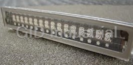
NORITAKE GU126x64D-K610A4

Description
Noritak GU126x64D-K610A4 Dot Graphic VFD Module, 126 x 64 High Brightness Dot Graphic Display
Part Number
GU126x64D-K610A4
Price
Request Quote
Manufacturer
NORITAKE
Lead Time
Request Quote
Category
VFD/LCD DISPLAYS
Datasheet

Extracted Text
Dot Graphic VFD Module GU126x64D-K610A4 � 126 x 64 High Brightness Dot Graphic Display The module includes the VFD glass, VF drivers and micro- � Single 5V DC Supply controller, character generation, interface logic and patented � 3 ASCII Fonts ( 5 x 5, 5 x 7, 10 x 14 ) transformerless DC/DC converter. The interface type is selected by � Asynchronous, SPI & Parallel interfaces a pushbutton on the back of the module. Auto key scanning and � Wide Temperature –40 to +85°C general I/O available on port PA0 – PA7. RS232/RS485 options. 2.5� x 4 Dimensions in mm. tolerances. 28.65 40.5 46.5 1 1 Uses patent applied PSU CON3 which has no inductive CON1 components. 1 Brown out detector active CON2 when RES is not connected. 17.6 57.45 3.0 10.7 93.0 1.5 96.0 7.7 1.6 2.4 ELECTRICAL SPECIFICATION CHARACTER SETS MINI FONT (PROPORTIONAL SPACING) Parameter Sym Min Typ Max Unit Condition Supply Voltage Vcc 4.5 5.0 5.25 V VSS=0V Supply Current Icc - 410 - mA Vcc=5V All dots Logic High Input VIH 3.0 - Vcc V VCC=5V Logic Low Input VIL -0.5 - 1.5 V VCC=5V Logic High Output VOH 4.2 - - V IOH =-3mA Vcc=5V Logic Low Output VOL - - 0.6 V IOL = 20mA 5x7 & 10x14 FONTS (FIXED SPACING) ENVIRONMENTAL and OPTICAL SPECIFICATION Parameter Value Display Area (XxY mm) 57.45 x 28.65 Dot Size/Pitch (XxY mm) 0.3 x 0.3/0.45 x 0.45 2 Luminance 800 cd/m Typ Colour of Illumination Blue-Green (Filter for colours) Operating Temperature -40�C to +85�C Storage Temperature -40�C to +85�C Operating Humidity (non condensing) 10 to 90% @ 25°C SOFTWARE COMMANDS Hex Command Hex Command 01-07 Run Macro 19 Reset 08 Backspace 1A + data Write Mode - direction 09 Horizontal Tab 1B + macro+len+data Set Macro 0A Line Feed 1B + 4D Erase All Macros 0B Home 1B + 4C/55 Lock/Unlock EEPROM 0C Vertical Tab 1B + 43 Request Checksum CON1 CON2 0D Carriage Return 1B + 50/46 Power On/Off Pin Async SPI Pin Signal 0E Clear End of Line 1B + 48/42 Enable/Disable Hex Write 15V 5V 10V 0F Test 1B + 49 + data Set Comms 2Nc SCK 2ENABLE 10 + x + y Cursor Position 1B + 44 + data Enable I/O Port 3RXD /SS 3 PA0 11 +xl+yt+xr+yb Set Area 1B + 4F + data Set Port Lines 4Nc SIN 4 PA1 12 +xl+yt+xr+yb Clear Area 1B + 52 Read Port 50V 0V 5 PA2 13 +xl+yt+xr+yb Invert Area 1B + 4B Enable key scanning 6Nc SOUT 6 PA3 14 +xl+yt+xr+yb Set Outline 1B + F8-FF Brightness 7TXD /IRQ 7 PA4 15 +xl+yt+xr+yb Clear Outline 1C / 1D / 1E Select Font 8 /RES /RES 8 PA5 *1 16 Set Pixel 1F +xl+yt+xr+yb+data Graphic Area Write 9MB MB 9 PA6 17 Clear Pixel 20 - FF Character Write 10 HB HB 10 PA7 *1 Applies to version 3 software only. Nc = Do Not Connect 18 + len + data Graphic Write The module defaults to an 8 line of 21 character display using the 5x7 font with single pixel spacing. The CONTACT cursor position auto increments after each character write. The bottom left of a character is placed at the Noritake Sales Office Tel Nos cursor x,y. The M(odule) Busy line indicates the module is busy when high. Connect the H(ost) Busy input Nagoya Japan: +81 (0)52-561-9867 to the MBusy to disable handshaking. Use the button to select the configuration, which is then stored in Canada: +1-416-291-2946 EEPROM. To send commands as hexadecimal, prefix the 2 bytes using character 60H. Chicago USA: +1-847-439-9020 Munchen (D): +49 (0)89-3214-290 Example: `10`3F`01 = Position dot x=64 y=1. To send character 60H to the display, send 60H twice. Itron UK: +44 (0)1493 601144 Rest Europe: +49 (0)61-0520-9220 Subject to change without notice. Doc Ref: 03894 Iss5 10 July 03 www.noritake-itron.com NORITAKE ITRON VFD MODULES GU126x64D-K610A4 Dot Graphic VFD Module GU126x64D-K610A4 SOFTWARE COMMANDS Instruction Data Format Description Macro Start 01H - 07H Start user defined macro 1-7. (BUSY time depends on contents) Backspace 08H Non destructive backspace. Cursor is moved left by the width of the currently select font. If the cursor is at the (50�s) left end of the display, no cursor movement is made. Horizontal Tab 09H Cursor is moved right by the width of the currently select font. If the cursor is at the end of the display, no (50�s) cursor movement is made. Line Feed 0AH Moves the cursor down by the height of the currently selected font. If the cursor is at the bottom of the display, (50us) no cursor movement is made. Home 0BH Moves the cursor horizontal position to 00H, the vertical positioning is dependent on the currently selected (50us) font, allowing for immediate character writing in the top-left corner of the display. Vertical Tab 0CH Moves the cursor up one character row. If the cursor is at the top of the top end of the display, no cursor (50us) movement is made. Carriage Return 0DH Moves the cursor horizontal position to 00H. The vertical position is unchanged. (50us) Clear EOL 0EH Clear all characters from the current cursor position to the end of the display. (2.5ms) Test 0FH Place module into self-test mode. The module will repetitively show a few test screens. The test mode will (50�s) stop on the next received byte. Cursor Position 10H + xpos + ypos Set the cursor position. (50us) Set Area 11H + xleft + ytop + xright + ybot Fill specified area. All dots within the specified area are illuminated. Please note that the cursor position is (50us + 1ms [last byte]) affected with this command. Clear Area 12H + xleft + ytop + xright + ybot Clear specified area. All dots within the specified area are cleared. Please note that the cursor position is (50us + 1ms [last byte]) affected with this command. Invert Area 13H + xleft + ytop + xright + ybot Invert specified area. All dots within the specified area are inverted. Please note that the cursor position is (50us + 1ms [last byte]) affected with this command. Set Outline 14H + xleft + ytop + xright + ybot Draw box outline. All dots within the specified outline are unchanged. Please note that the cursor position is (50us + 1ms [last byte]) affected with this command. Clear Outline 15H + xleft + ytop + xright + ybot Clear box outline. All dots within the specified outline are unchanged. Please note that the cursor position is (50us + 1ms [last byte]) affected with this command. Set Pixel 16H Illuminate a single pixel at the current cursor position. (50us) Clear Pixel 17H Clear a single pixel at the current cursor position. (50us) Graphic Write 18H + len + data Write graphical data, length len, direct to display. See write mode command (1AH) for graphic orientation and (50us + 250us [each data byte]) cursor movements. Reset 19H Resets display to power-on defaults: - Display is cleared. 5x7 font selected. Write Mode = 00H (500us) Brightness Level = 7. VFD Power = On. Write Mode 1AH + data Bit 7 = graphic data orientation - 0 = horizontal, 1 = vertical (default = horizontal) (50us) Bit 6 = cursor movement - 0 = horizontal, 1 = vertical (default = horizontal) Bit 5 = cursor direction - 0 = forward, 1 = backwards (default = forwards) Bit 4 = underscore cursor - 0 = off, 1 = on (default = off) Bit 3 = underscore cursor - 0 = static, 1 = flash (default = static) Bit 1/0 = pen type - 00 = overwrite, 01 = AND, 02 = OR, 03 = XOR (default = overwrite) Set Macro 1BH + macro + len + data Send macro data to EEPROM. macro = 00H - 07H. Macro0 is executed at power-up only. A maximum of 480 (50us) bytes is allowed for macro data. The display may flicker whilst writing macro data. Brightness 1BH + level Set the display brightness. level = F8H - FFH. F8H = display off. F9H = minimum, FFH = maximum (default). (50us) Erase Macros 1BH + 4DH Clear all downloaded macros in EEPROM. Screen may blank momentarily while macro data is being erased. (80ms) Lock/Unlock EEPROM 1BH + 4CH / 55H All data contained within the non-volatile EEPROM is locked (4CH), and no changes are possible until the (50us + 10ms [last byte]) unlock command (55H) is executed. Checksum 1BH + 43H All data received is added to the checksum. This command will read the lower 8-bits of that checksum, before (50us) being cleared. Please note that the checksum is cleared when executing the test mode. Power On/Off 1BH + 50H / 46H 50H = Turn on VFD power supply (default). (50us) 46H = Turn off VFD power supply, display’s contents will be preserved. Hex/Binary Mode 1BH + 48H / 42H 48H = Enable hex receive mode, character 60H is interpreted as a hexadecimal prefix. (50us) 42H = Disable hex receive mode. Hex mode is enabled at power up. Set ASYNC Comms 1BH + 49H + data Set asynchronous communication baud rate and parity. Takes effect at power-up or hardware reset. (50us + 10ms[last byte]) Bit 7 = Automatic I/O send (0=off, 1=on). Bits 1&0 = baud rate (00=4800, 01=9600, 02=19200, 03=38400). Bit 2 = Parity (1=even, 0=none) (factory default = 19200 with no parity, automatic I/O send is off) Enable I/O Port 1BH + 44H + data Set I/O port direction. A ‘1’ indicates an input, a ‘0’ an output. All output lines are immediately set low. All input (50us + 20ms[last byte]) lines have their pull-ups enabled. This value is stored in EEPROM and will automatically be set at power up. Set Port Lines 1BH + 4FH + data Set Output lines on I/O port, a ‘1’ will set 5V on the output ports, or enable the pull-ups on the inputs. (50us) Read Port 1BH + 52H Read current I/O port status. A single byte is transmitted showing the current state of the I/O lines. (50us) Enable Key Scanning 1BH + 4BH Set I/O port to key scanning. The I/O ports are continuously scanned for any key press. This mode is stored in (50us + 10ms[last byte]) EEPROM and will automatically be selected at power up. Select Font 1CH / 1DH / 1EH Select font. 1CH = proportional mini font. 1DH= fixed spaced 5x7 font. 1E = fixed spaced 10x14 font. (50us) Graphic Area Write 1FH + xl + yt + xr + yb + data Write graphic data within defined area. See write mode command (1AH) for graphic orientation and cursor (50us + 250us [each data byte]) movements. Note: This command is available on software version 3 only. Press setup button to view. Hex Prefix 60H + dhH + dlH Write to the display module using a 2-byte hexadecimal number. dhH = high nibble, dlH = low nibble. E.g. (50�s + 50us + command BUSY) Sending `19 will reset the display. Character Write 20H – FFH Display character from selected font. (500us) Notes: - Busy times are not inclusive of a 100us scan period, this must be taken into consideration. If the cursor is enabled, busy times will increase by a further 50us. All coordinates are absolute. The origin (00H, 00H) is the top left of the display. All data shown is in hexadecimal format. NORITAKE ITRON VFD MODULES GU126x64D-K610A4 Dot Graphic VFD Module GU126x64D-K610A4 GU126x64D-K610A4 SETUP The VFD module features two serial ports (synchronous & asynchronous) and a parallel port, all interfaces are TTL compatible. Interface selection/set-up can be made using the single push button switch on the back of the module. Pressing the switch for the first time will display the initial configuration menu. On each subsequent switch press the menu pointer will advance. The current menu item will be selected if the switch is not pressed within 2 seconds. To select the required interface, press the switch until the ‘COMMS’ item has been selected. Wait 2 seconds for the communication menu to be displayed. Press the switch until the required interface is selected. The factory default interface is SPI. Wait another 2 seconds to display the related communication settings. The current configuration is displayed first. Interface selection example. SYNCHRONOUS SERIAL COMMUNICATION With synchronous communications enabled, data can be clocked into the VFD module using the rising or falling edge of SCK. This is selectable by the push switch on the rear of the module, which also sets the data order. By default, data is clocked in on the rising edge with the most significant bit sent first. The host must provide adequate delays for the module to process the data, these busy times are specified in the software command section. Alternatively the host can monitor the MB (Module Busy) line. >125ns tBUSY + 10us SIN I/O /SS I/O SOUT >65ns >125ns >125ns HOST I/O SCK GU126x64D-K610A4 SYSTEM SCK (RISING) I/O /SS I/O MB SCK (FALLING) I/O /RES GND VDD VDD GND SIN (D7-D0) D7 D6 D0 D7 D6 D0 SIN (D0-D7) D0 D1 D7 D0 D1 D7 <10us The /SS pin can be used as an enable pin if other devices are MB connected to the serial line, and also allows byte synchronisation. TTL Synchronous serial communication. The use of the /SS line is optional, and can be permanently pulled low if required. ASYNCHRONOUS SERIAL COMMUNICATION The asynchronous communication speed and parity can be set with the push switch on the rear of the module, or with the ‘UART SETUP’ command. The default settings are 19200 baud with no parity. Again the host most provide adequate delays for the module to process the command and data. The module busy line (MB) will go high when data is currently being processed. <10us tBUSY START D0 D1 D2 D3 D4 D4 D5 D6 D7 PARITY STOP RXD TXD RXD RXD TXD HOST GU126x64D-K610A4 MB I/O HB SYSTEM MB I/O TTL Asynchronous serial communication from host system to VFD module. I/O /RES >2us GND VDD VDD GND START D0 D1 D2 D3 D4 D4 D5 D6 D7 PARITY STOP TXD HB The host busy line (HB) stops the module from sending data to TTL Asynchronous serial communication from VFD module to host system. the host until the line falls. The use of the HB and MB lines are optional, and can be connected together if not required. PARALLEL COMMUNICATION The 8 I/O lines can be configured as a slow parallel interface. Data on PA0-7 is clocked into the module with the Enable line, this can be set to either a rising or falling edge trigger by the push switch on the back of the module. The host must keep the data stable for the time period indicated in the timing diagram. The module busy line (MB) can be used in parallel communication mode. >125ns ENABLE (RISING) I/O PA0-7 HOST GU126x64D-K610A4 ENABLE (FALLING) SYSTEM I/O MB >125ns >250ns I/O ENABLE D0 - D7 DATA GND VDD VDD GND tBUSY <10us MB Parallel Communication. NORITAKE ITRON VFD MODULES GU126x64D-K610A4 Dot Graphic VFD Module GU126x64D-K610A4 RESET TIMING >50ns The module is reset when a low-level signal is applied to the /RES line. This will cause the /RES module to clear the display, initialise the communication settings and set all power-up 30ms defaults. During this initialisation period, the user must delay any transmission to the module. DATA I/O level change interrupt. KEYBOARD CONTROL All 8 I/O lines can be configured to scan a key matrix with up to 16 keys. The 1BH + 4BH command will configure the I/O lines to key scan mode. The I/O port status will indicate the row/column position of the pressed key. The ENABLE line acts as hardware scan enable input, and should be tied to ground. The following example enables the key-scanning mode and the automatic I/O send when using asynchronous communications. PA0 S1 S2 S3 S4 PA1 ENABLE KEY SCANNNG AUTOMATIC I/O SEND S5 S6 S7 S8 PA2 1BH 4BH 1BH 49H 82H S9 S10 S11 S12 PA3 GU126x64D S13 S14 S15 S16 On each key press, the I/O port status will be sent out of the asynchronous -K610A4 communication port. e.g. pressing key switch 1, the module will send 03H to the host system. PA4 PA5 PA6 PA7 When using synchronous serial communication, the /IRQ line will indicate when a key ENABLE has been pressed, the host should then issue a ‘Read Port’ command to determine the I/O port status. I/O CONTROL The module contains simple Input and Output functions for the 8 I/O lines (PA0-PA7). All inputs include an optional pull-up resistor, 30K-120K in value. The outputs can source ~5mA and sink ~30mA. The following example sets up the I/O lines to control the 2 LED’s and provide a pull-up resistor for the switch. VDD ENABLE I/O MODE P0/1 = OUT, P7 = IN SET I/O LINES ENABLE P7 PULL-UP, TURN ON LED1&2 GU126x64D- K610A4 LED1 LED2 1BH 44H 80H 1BH 4FH 80H PA0 PA1 With asynchronous communications enabled, the status of PA0-PA7 can be transmitted when a change in PA7 level is detected on any pin. This automatic response mode can be enabled by using the ‘UART SETUP’ command. When this mode is enabled, the VFD module can reliably check port changes every 15ms. With GND SW1 auto send disabled (default) a manual read command is required to determine the port status. READ PORT SW1 CLOSED SW1 OPEN RESPONSE 1BH 52H 00H 80H < 15ms > 1us /IRQ When using synchronous serial communications, the host can detect a level change with the /IRQ line on CON1. This allows the host to PA0 - PA7 poll the port status only when needed. I/O level change interrupt. I/O WRITE I/O READ ~400ns ~400ns When I/O control is used, the Enable line can be used as an active low ENABLE read or write strobe. With the I/O read command, the enable line will <250ns <250ns clock before the module reads the I/O port status. With the I/O write PA0 - PA7 command, the enable line will clock after the I/O lines have been set. I/O Write & Read. NORITAKE ITRON VFD MODULES GU126x64D-K610A4 Dot Graphic VFD Module GU126x64D-K610A4 DISPLAYING TEXT 0,0 The module contains 3 font sizes, a proportional mini-font, 5x7 pixel, and a 10x14 pixel font. Characters of any size can be written to any part of the display. All data sent to the module from 20H to FFH is treated as character data. Characters are positioned above the current cursor position, see Fig1. Each character written will include a one pixel space on the right side of the character. After each character is written to the display, the cursor position is automatically advanced. If the cursor position reaches the end of the display, the host must reposition to the next line. 0,7 6,7 The following example displays two text messages in the center of the display. Cursor Positioning, example of writing 2 characters from cursor position 0,7. 5x7 FONT SET CURSOR DISPLAY TEXT SET CURSOR DISPLAY TEXT 1DH 10H 15H 1FH ‘NORITAKE ITRON’ 10H 1EH 27H ‘VFD MODULES’ The next example displays one line of text using the 10x14 font. 10x14 FONT SET CURSOR DISPLAY TEXT Displaying text in the small 5x7 font. 1EH 10H 21H 27H ‘126x64’ The module can display a cursor to aid character positioning and text input. The size of the cursor depends upon the currently selected font, and can be set to flash or remain static. 5x7 FONT SET CURSOR DISPLAY TEXT ENABLE FLASHING CURSOR Displaying text in the large 10x14 font. 1DH 10H 0DH 0EH ‘ENTER NAME: ’ 1AH 18H DISPLAYING GRAPHICS Using the cursor to aid user input. Graphical images can be displayed on the VFD module in either a horizontal or vertical byte orientation. After each graphical data write, the cursor is automatically advanced, depending upon the direction selected in the ‘Write Mode’ command. The most significant bit is positioned to the top (vertical data) or to the left (horizontal data). Two commands are available, 18H for small data length and 1FH for large images. MSB - 1CH The following example displays a simple graphical image using horizontal graphic data using 18H. The - 5CH write mode is first set to horizontal data format, with a vertical cursor movement. The cursor is positioned - 48H - 3EH before sending the 8 byte of graphical data using the graphics command. - 1DH - 1DH - 14H - 36H SET HORIZONTAL WRITE MODE Graphic Image using horizontal data SET CURSOR GRAPHIC WRITE LENGTH GRAPHIC DATA MSB 1AH 40H 10H 1FH 1CH 18H 08H 1CH 5CH 48H 3EH 1DH 1DH 14H 36H The next example displays a simple graphical image using vertical graphical data with 18H. The write mode is first set to vertical data format, with a horizontal cursor movement. The cursor is positioned, then the top 20 bytes are sent using the graphic write command. The cursor is then repositioned to send the bottom 20 graphical bytes. SET VERTICAL WRITE MODE SET CURSOR GRAPHIC WRITE LENGTH GRAPHIC DATA Graphic Image using vertical data 1AH 80H 10H 47H 18H 18H 14H 00H 00H 00H 00H 07H 04H C7H FEH 72H 73H 32H 3EH 3FH 1DH 00H 00H 00H 00H 00H 00H 10H 47H 20H 18H 14H 00H 3CH 42H 81H B9H C1H 42H 7CH 20H D8H FCH 3CH FCH CAH 49H B1H 89H 42H 3CH 00H The graphic area write command 1FH uses top-left and bottom-right XY co-ordinates to define an area to which graphical data bytes will be written. The orientation is set-up using the write mode command 1AH. Unused bits are masked where the screen area is not a byte multiple. Displaying graphic images in vertical and horizontal format. NORITAKE ITRON VFD MODULES GU126x64D-K610A4 BYTE21 BYTE1 BYTE2 BYTE19 BYTE40 BYTE20 Dot Graphic VFD Module GU126x64D-K610A4 AREA COMMANDS The VFD module contains commands to fill, clear and invert defined areas of the display. Also an outline command is available to draw rectangles around objects. The following example displays three options for the user to select, each option is contained within a box with a shadow effect. Drawing horizontal and vertical line using the fill area command creates the shadow effect. SET CURSOR DISPLAY OPTIONS 10H 05H 23H ‘SETUP’ 10H 2FH 23H ‘PRINT’ 10H 5EH 23H ‘RUN’ Display options with simple text write. BO BOX X O OU UT TL LI INE NE T TO OP P LE LEFT FT BO BOT TT TO OM M RI RIG GH HT T 14H 00H 1AH 26H 24H 14H 2AH 1AH 50H 24H 14H 54H 1AH 7AH 24H Boxes created using the ‘Set Outline’ command. SET AREA HORIZONTAL LINE FILL AREA VERTICAL LINE 11H 01H 25H 27H 25H 11H 27H 1BH 27H 25H 11H 2BH 25H 51H 25H 11H 51H 1BH 51H 25H 11H 55H 25H 7BH 25H 11H 7BH 1BH 7BH 25H Drop Shadows created with the ‘Set Area’ command. The next example uses the invert area command to select one of the options. TOP LEFT INVERT AREA BOTTOM RIGHT 13H 55H 1BH 79H 23H Option ‘Run’ selected with the ‘Invert Area’ command. WRITE MODES By default, display data that is overwritten will be cleared prior to displaying any new data. This display data can be maintained whilst writing by selecting the ‘OR’ mode with the ‘Write Mode’ command, this will effectively merge the old data with the new. The ‘AND’ write mode will only display written data if existing data is present on the display. The other ‘Write Mode’ is ‘XOR’ which can be useful for writing text on an inverted display. The following example uses the XOR mode to write text on a full display. WRITE MODE XOR MODE SET AREA TOP LEFT BOTTOM RIGHT 11H 00H 00H 7DH 3FH 1AH 03H 10H 18H 23H ‘INVERETED TEXT’ Displaying inverted text using the ‘Write Mode’ command. This next example uses the XOR mode to display the percentage completed on a progress bar. WRITE MODE XOR MODE 10H 26H 1DH ‘PROGRESS’ 14H 00H 22H 7DH 2CH 11H 00H 22H 3CH 2CH 1AH 03H 10H 38H 2BH ‘50%’ Using inverting text for displaying progress level. NORITAKE ITRON VFD MODULES GU126x64D-K610A4 Dot Graphic VFD Module GU126x64D-K610A4 MACROS A string of data and commands can be sent to the module and stored in non-volatile EEPROM by using the macro feature. This string of data and commands can then be executed by using just one command. Up to 8 macros can be used at any one time, one of these is executed at power-up. This example uses the first macro (Macro 0) to display an initial message at power-up. WRITE TO MACRO-0 LENGTH POWER-UP MESSAGE 1BH 00H 24H 10H 1EH 1DH ‘PLEASE WAIT’ 10H 06H 29H ‘INITIALISING SYSTEM’ Power-Up message using Macro 0. This next example saves the previous graphic icon into Macro 1, and then is used as a user-defined character. WRITE TO MACRO-1 LENGTH GRAPHIC DATA 1BH 01H 0CH 1AH 40H 18H 08H 1CH 5CH 48H 3EH 1DH 1DH 14H 36H SET CURSOR DISPLAY ICON SET CURSOR DISPLAY ICON 10H 05H 15H 01H 10H 72H 14H 01H 10H 35H 1EH 01H 10H 46H 26H 01H Using Macros as user-defined characters. This example creates a display template, which can be helpful if many screens require the same look. WRITE TO MACRO-2 LENGTH RESET AREA COMMANDS 1BH 02H 1BH 19H 14H 02H 02H 7BH 3DH 11H 00H 00H 04H 04H 11H 00H 3BH 04H 3FH 11H 79H 00H 7DH 04H 11H 79H 3BH 7DH 3FH DISPLAY TEMPLATE SET CURSOR DISPLAY MESSAGE 02H 10H 1CH 23H ‘SYSTEM READY’ Using Macros as a screen template. EEPROM PROTECTION The EEPROM contains information such as macro data, asynchronous communication settings and I/O configuration. So it is important to protect this information from stray commands due to communication failures. To protect the EEPROM, the module contains a ‘EEPROM Lock’ command (1BH + 4CH). Once this command is issued, no further EEPROM updates can be made until it is unlocked (1BH + 55H). This feature is also accessible from the set up menu, using the push button switch on the rear of the module. USING THE CHECKSUM All data written to the module is added to an internal checksum. The lower 8-bits of this checksum can be read at any time from the module by the host system to confirm accurate data transfer. It is up to the user if or when this feature should be used. The checksum is cleared at power-up and after each checksum read. Example: Read checksum at power-up, or directly after it has been cleared. READ CHECKSUM CHECKSUM SENT TO HOST 1BH 43H 5EH Example: Read checksum after data has been written to the display. WRITE DATA READ CHECKSUM CHECKSUM SENT TO HOST 19H 31H 32H 33H 1BH 43H 0DH NORITAKE ITRON VFD MODULES GU126x64D-K610A4
Frequently asked questions
What makes Elite.Parts unique?

What kind of warranty will the GU126x64D-K610A4 have?
Which carriers does Elite.Parts work with?
Will Elite.Parts sell to me even though I live outside the USA?
I have a preferred payment method. Will Elite.Parts accept it?


What they say about us
FANTASTIC RESOURCE
One of our top priorities is maintaining our business with precision, and we are constantly looking for affiliates that can help us achieve our goal. With the aid of GID Industrial, our obsolete product management has never been more efficient. They have been a great resource to our company, and have quickly become a go-to supplier on our list!
Bucher Emhart Glass
EXCELLENT SERVICE
With our strict fundamentals and high expectations, we were surprised when we came across GID Industrial and their competitive pricing. When we approached them with our issue, they were incredibly confident in being able to provide us with a seamless solution at the best price for us. GID Industrial quickly understood our needs and provided us with excellent service, as well as fully tested product to ensure what we received would be the right fit for our company.
Fuji
HARD TO FIND A BETTER PROVIDER
Our company provides services to aid in the manufacture of technological products, such as semiconductors and flat panel displays, and often searching for distributors of obsolete product we require can waste time and money. Finding GID Industrial proved to be a great asset to our company, with cost effective solutions and superior knowledge on all of their materials, it’d be hard to find a better provider of obsolete or hard to find products.
Applied Materials
CONSISTENTLY DELIVERS QUALITY SOLUTIONS
Over the years, the equipment used in our company becomes discontinued, but they’re still of great use to us and our customers. Once these products are no longer available through the manufacturer, finding a reliable, quick supplier is a necessity, and luckily for us, GID Industrial has provided the most trustworthy, quality solutions to our obsolete component needs.
Nidec Vamco
TERRIFIC RESOURCE
This company has been a terrific help to us (I work for Trican Well Service) in sourcing the Micron Ram Memory we needed for our Siemens computers. Great service! And great pricing! I know when the product is shipping and when it will arrive, all the way through the ordering process.
Trican Well Service
GO TO SOURCE
When I can't find an obsolete part, I first call GID and they'll come up with my parts every time. Great customer service and follow up as well. Scott emails me from time to time to touch base and see if we're having trouble finding something.....which is often with our 25 yr old equipment.
ConAgra Foods