

 Manufacturers
NORITAKE CU24063-Y100

Description
Noritake CU24063-Y100 Vacuum Fluorescent Display - Dot Graphic Module
Part Number
CU24063-Y100
Price
Request Quote
Manufacturer
NORITAKE
Lead Time
Request Quote
Category
PRODUCTS - C
Specifications
Display area
70.38 x 22.69 mm
Operating humidity
20 to 80 % R.H
Operating temperature
-40 to +85 ºC
Storage temperature
-40 to +85 ºC
Features
- Blink ON/OFF
- Cursor, Underline ON/OFF
- Font Magnification
- Highlight Function
- Horizontal scroll mode
- Power save mode
- Screen saver
Datasheet

Extracted Text
RoHS 2002/95/EC
Vacuum Fluorescent Display
Module
Specification
Model: CU24063-Y100
Specification No: DS-1572-0001-00
Date of Issue: January 29, 2009 (00)
Revision:
Published by
NORITAKE ITRON CORP. / Japan
http://www.noritake-itron.jp
This specification is subject to change without prior notice.
This product complies with RoHS Directive 2002/95/EC
CU24063-Y100
Index.
1 General Description ................................................................................................................................3
1.1 Scope...............................................................................................................................................3
1.2 Features...........................................................................................................................................3
1.3 Hardware Configuration................................................................................................................4
1.3.1 Block Diagram..........................................................................................................................4
2 Electrical Specification...........................................................................................................................4
2.1 Absolute Maximum Ratings..........................................................................................................4
2.2 Electrical Ratings............................................................................................................................4
2.3 Electrical Characteristics...............................................................................................................5
3 Optical Specifications.............................................................................................................................6
4 Environmental Specifications...............................................................................................................6
5 Physical Specifications..........................................................................................................................6
6 Applicable Specifications......................................................................................................................6
7 Interface......................................................................................................................................................6
7.1 Parallel Interface.............................................................................................................................7
7.1.1 Basic Operation.........................................................................................................................7
7.1.2 Flowchart ..................................................................................................................................7
7.1.3 Interface Timing........................................................................................................................8
7.2 Serial Interface................................................................................................................................9
7.2.1 Basic Operation.........................................................................................................................9
7.2.2 Flowchart ..................................................................................................................................9
7.2.3 Asynchronous Serial Interface Timing....................................................................................10
7.2.3.1 Data write ..............................................................................................................................10
7.2.3.2 Data read...............................................................................................................................10
7.3 Reset Timing.................................................................................................................................11
8 Jumper Setting.......................................................................................................................................12
8.1 Jumper location............................................................................................................................12
8.1.1 Baud Rate Setting (for Asynchronous Serial Interface only)..................................................12
8.1.2 Test Mode................................................................................................................................12
9 Operating Mode......................................................................................................................................13
9.1 Direct Command Mode ...............................................................................................................13
9.2 User Set up Mode........................................................................................................................13
9.3 Serial OUT Mode..........................................................................................................................13
9.4 Test mode......................................................................................................................................13
10 Font Table Configuration.................................................................................................................14
11 Display Area-End of Line Behavior...............................................................................................15
12 Initial setting........................................................................................................................................17
13 Commands...........................................................................................................................................17
13.1 Command Configuration.............................................................................................................17
13.2 Command Set...............................................................................................................................18
13.3 Detail of Command Set...............................................................................................................19
13.3.1 Character display ....................................................................................................................19
13.3.2 Back Space..............................................................................................................................20
13.3.3 Horizontal Tab.........................................................................................................................20
13.3.4 Line Feed ................................................................................................................................21
13.3.5 Home Position.........................................................................................................................21
13.3.6 Display Clear ..........................................................................................................................22
- 1 -
CU24063-Y100
13.3.7 Carriage Return.......................................................................................................................22
13.3.8 Underline cursor mode............................................................................................................22
13.3.9 Cursor off mode ......................................................................................................................22
13.3.10 Block cursor mode ..................................................................................................................22
13.3.11 Underline cursor blink mode...................................................................................................22
13.3.12 Cursor set ................................................................................................................................22
13.3.13 Initialize display......................................................................................................................23
13.3.14 RAM user font ........................................................................................................................23
13.3.15 Define RAM user font.............................................................................................................24
13.3.16 Delete RAM user font.............................................................................................................25
13.3.17 Character blink mode OFF......................................................................................................25
13.3.18 Character blink mode ON .......................................................................................................25
13.3.19 Specify quick write mode .......................................................................................................25
13.3.20 Specify International font set ..................................................................................................26
13.3.21 Specify flickerless write mode................................................................................................26
13.3.22 Blink speed control .................................................................................................................27
13.3.23 Underline display mode ON ...................................................................................................27
13.3.24 Underline display mode OFF..................................................................................................27
13.3.25 Insert character........................................................................................................................27
13.3.26 Delete character ......................................................................................................................28
13.3.27 Insert line ................................................................................................................................28
13.3.28 Delete line ...............................................................................................................................28
13.3.29 Reset........................................................................................................................................28
13.3.30 Specify character code type ....................................................................................................28
13.3.31 Over-write mode .....................................................................................................................29
13.3.32 Vertical scroll mode ................................................................................................................29
13.3.33 Horizontal scroll mode............................................................................................................29
13.3.34 Horizontal scroll speed............................................................................................................29
13.3.35 Brightness level setting ...........................................................................................................29
13.3.36 Wait.........................................................................................................................................30
13.3.37 Display blink...........................................................................................................................30
13.3.38 Screen saver ............................................................................................................................31
13.3.39 User set up mode start.............................................................................................................31
13.3.40 User set up mode end..............................................................................................................31
13.3.41 Define FROM user font ..........................................................................................................32
13.3.42 Read Status information..........................................................................................................33
13.3.43 Display Status information......................................................................................................33
13.3.44 Serial OUT mode start ............................................................................................................33
13.3.45 Serial OUT mode end .............................................................................................................34
13.3.46 Select / Deselect 5×8 Matrix font ...........................................................................................34
13.3.47 Select/Deselect Alternative Magnified Font ...........................................................................35
13.3.48 Font Magnification..................................................................................................................36
13.3.49 Individual Character Brightness Level Setting .......................................................................37
14 Pin Configuration...............................................................................................................................38
14.1 Parallel interface connecter (Fourteen through-holes / CN3)................................................38
14.2 Serial interface connector (Six through-holes / CN2).............................................................38
15 Firmware Version Notation..............................................................................................................38
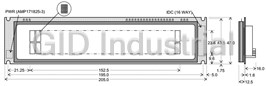
16 Physical Dimensions.........................................................................................................................39
Notice for the Cautious Handling VFD Modules....................................................................................40
Revision Note..................................................................................................................................................41
- 2 -
CU24063-Y100
1 General Description
1.1 Scope
This specification covers the operation and operating requirements of the Vacuum Fluorescent
Display (VFD) module CU24063-Y100.
1.2 Features
• Functions
o Character highlight
o Easy to use ASCII commands and fonts.
o Character Magnification
o Screen Saver
o Blink Action Command(Display or Character)
• Display
o Vivid green indication
o Wider viewing angle
2
o High Brightness (Typ. 2000 cd/m )
o Brightness Levels: 8 levels of overall display brightness with 8 relative levels for each
individual 5×8 Matrix
• Font
o New 5×8 Matrix Character Font
o Many International Font Sets
o RAM User-Definable Characters (16 characters)
o FROM User-Definable Characters (224 characters)
o 144 (24×6) Characters on the compact display area
• Interface
o Parallel Interface: i80 type 8bit bus(C MOS Signal level)
o Serial Interface: Asynchronous(RS232 level)
• Operation
o DC 5V input
o Wide Operation Temperature Range (−40 ~ +85ºC)
- 3 -
CU24063-Y100
1.3 Hardware Configuration
The module consists of:
24 x 6 character Display (VFD)
Refresh RAM
Character generator
DC/DC converter (Supply all necessary power for VFD)
Display controller
All necessary control logic circuits
1.3.1 Block Diagram
Parallel IF Parallel IF Controller VFD
Circuit
Firmware
Character font
Serial IF
Serial IF
Flash-Memory
Circuit
(User font table)
Jumper
Swiitch
VDD2
VCC
DC/DC
EF1 Note: Flash memory re-write rating
Converter
is approximately 10,000 times.
GND EF2
2 Electrical Specification
2.1 Absolute Maximum Ratings
Parameter SymbolMin.Typ.Max. Unit
Power Supply Voltage V −0.3 - +6.0 V
CC DC
Logic Supply Voltage
V −0.3 - V +0.3 V
IN CC DC
D0-D7, /WR, /RESET
Logic Supply Voltage
V −20.0 - +20.0 V
IN DC
SIN
2.2 Electrical Ratings
Parameter SymbolMin. Typ. Max. Unit
Power Supply Voltage V 4.75 5.0 5.25 V
CC DC
- 4 -
CU24063-Y100
2.3 Electrical Characteristics
Measuring Conditions: Ambient temperature = 25 ºC, V = 5.0 V
CC DC
Parameter SymbolMin. Typ. Max.UnitCondition Note
‘L’ Level D0-D7, /WR,
I - - −0.15 mA V = 0V -
IL IN
Logic Input Current /RESET
D0-D7 I - - 5.0 µA V = 5V -
IH1 IN
‘H’ Level
Logic Input Current
/WR, /RESET I - - 0.25 µA V = 5V -
IH2 IN
Logic Input
SIN R 3 - - KOhm - -
IN
Resistance
D0-D7, /WR V 0 - 0.2×V V - -
IL1 CC DC
‘L’ Level
/RESET V 0 - 0.8 V - -
Logic Input Voltage IL2 DC
SIN V -15 - 0.5 V - -
IL3 DC
D0-D7, /WR,
- - -
V 0.8×V V V
IH1 CC CC DC
/RESET
‘H’ Level
Logic Input Voltage
SIN 3.0 - +15 - -
V V
IH2 DC
PBUSY V - - 0.1 V I = 50µA -
OL1 DC OL
‘L’ Level
Logic Output Voltage
SBUSY V 0 - 0.5 V R = 3KOhm -
OL2 DC L
PBUSY V V −0.1 - - V I = −50µA -
OH1 CC DC OH
‘H’ Level
Logic Output Voltage
SBUSY 4.0 - R = 3KOhm -
V V V L
OH2 CC DC
Brightness
- 320 400 (1)
I -1 mA
CC1 DC
100%
Brightness
I -1 - 260 330 mA (2)
CC2 DC
100%
Brightness
Power Supply Current
I -2 - 420 530 mA (1)
CC1 DC
200%
Brightness
I -2 - 310 390 mA (2)
CC2 DC
200%
Power Save
- 25 35 (3)
I mA
CC3 DC
Mode
Brightness
- 1.6 2.0 W (1)
100%
Power Consumption -
Brightness
- 2.1 2.65 W (1)
200%
(1) I shows the current when all dots in the display are on.
CC1
(2) I shows the current when all dots in the display are off.
CC2
(3) I shows the current with the Power Save Mode. Power save mode is one of the options of
CC3
“Screen saver” command. Please refer to “Screen saver” command at Page 31.
Note: A slow start power supply may cause erroneous operations. I can be
CC
approximately twice the specified supply current at power on.
- 5 -
CU24063-Y100
3 Optical Specifications
2 2
Luminance: Minimum 350 cd/m , typically 1000 cd/m (100% brightness)
2
Typically 2000 cd/m (200% brightness)
Color of illumination: Green (Blue Green)
4 Environmental Specifications
Operating temperature: −40 to +85 ºC
Storage temperature: −40 to +85 ºC
Operating humidity: 20 to 80 % R.H (non-condensing)
Storage humidity: 20 to 80 % R.H (non-condensing)
Vibration: 10-55-10Hz, all amplitude 1mm, 30 minutes, X-Y-Z (non-operating)
2
Shock: 392m/s (40G) 9ms X-Y-Z, 3 times each direction (non-operating)
5 Physical Specifications
Number of characters: 144(24 characters x 6 lines)
Matrix format: 5 × 8 dots
Display area: 70.38 x 22.69 mm (X × Y)
Character size: 2.07 x 3.34 mm (X × Y)
Character pitch: 2.97 mm
Line pitch: 3.87 mm
Dot size: 0.334 x 0.33 mm (X × Y)
Dot pitch: 0.434 x 0.43 mm (X × Y)
Weight: Approximately 56 g
6 Applicable Specifications
Applicable reliability spec: TT-99-3102
Applicable production spec: TT-98-3413
7 Interface
Parallel Interface: i80 type 8bit bus(C MOS Signal level)
Serial Interface: Asynchronous(RS232 level)
The module cannot receive both serial and parallel data at the same time.
8 bit Parallel Interface Asynchronous Serial Interface
8bit DATA
SIN
Host Y series Host Y series
WR
System Display System Display
PBUSY SBUSY
Module Module
Monitoring the busy line is strongly recommended, because it prevents data loss and
minimizes a waiting time to write next data.
- 6 -
CU24063-Y100
7.1 Parallel Interface
7.1.1 Basic Operation
Data (D0-D7) has to be set prior to a rising edge of /WR line, and the data is clocked in on the
rising edge of /WR line.
During data execution, the parallel busy line is high (PBUSY=1).
Writing data when PBUSY = 1 causes data loss, so please write data when PBUSY = 0.
7.1.2 Flowchart
Start to send data
NO
PBUSY = 0?
YES
/WR = 0
Set D0-D7
/WR = 1
Wait (Min. 20uS)
NO
Continue to
send data ?
YES
End
- 7 -
CU24063-Y100
7.1.3 Interface Timing
Min.
100ns
1
/WR
0
Min. Min.
50ns 20000ns
1
D0-D7
0
Max. Min.
40ns 0ns
1
PBUSY
0
Note: Monitoring the parallel busy line (PBUSY) is strongly recommended, because it
prevents data loss and minimizes a waiting time to write next data. Please write data when
PBUSY = 0.
- 8 -
CU24063-Y100
7.2 Serial Interface
7.2.1 Basic Operation
Default setting: Asynchronous Serial Interface (Baud rate = 38,400bps)
The capacity of the receiving buffer is 64 bytes. The relationship between SBUSY and the
receiving buffer is as follows;
Remaining space of receiving buffer
SBUSY 0 -> 1 16 byte or less
SBUSY 1 -> 0 24 byte or more
Writing data when SBUSY = 1 may cause data loss, so please write data when SBUSY = 0.
7.2.2 Flowchart
Start to send data
NO
SBUSY = 0?
YES
Send one byte data
NO
Continue to
send data ?
YES
End
- 9 -
CU24063-Y100
7.2.3 Asynchronous Serial Interface Timing
7.2.3.1 Data write
0
SIN
1
Max. Min.
30μs 0μs
0
SBUSY
1
Protocol:
9,600 ~ 115,200bps
Baud rate
(Selectable by Jumper)
Default: 38,400bps
Parity None
Format Start (1bit)+Data (8bit)+Stop (1bit)
Handshake SBUSY
Note: Monitoring the serial busy line (SBUSY) is strongly recommended, because it
prevents data loss and minimizes a waiting time to write next data. Please write data when
SBUSY = 0.
7.2.3.2 Data read
This is used for Read states information command only.
0
SIN
1
Min.
Min.
Min.
0μs
20μs
0μs
0
SOUT
1
Protocol:
9,600 ~ 115,200bps
Baud rate
(Selectable by Jumper)
Default: 38,400bps
Parity
None
Format Start (1bit)+Data (8bit)+Stop (1bit)
Handshake None
Note: Output data is transferred collectively from a VFD module, so a receiving buffer may
be required on a host system to prevent data loss.
- 10 -
CU24063-Y100
7.3 Reset Timing
Reset pulse (active low) should be longer than 1ms.
The module sets the SBUSY/PBUSY line upon receipt of Reset signal and clears the line when
ready to receive data.
Min.
1ms
/RESET
Max.
100ms
PBUSY
SBUSY
Min.
0μs
SIN
Min.
0μs
/WR
- 11 -
CU24063-Y100
8 Jumper Setting
8.1 Jumper location
Components side
JT J2* J1 J0 BT*
CN3
CN2
Note: Jumper “J2” and “BT” is for factory use only. Please do not change.
8.1.1 Baud Rate Setting (for Asynchronous Serial Interface only)
Baud Rate J0 J1
38,400bps (Default) OPEN OPEN
19,200bps SHORT OEPN
9,600bps OPEN SHORT
115,200bps SHORT SHORT
8.1.2 Test Mode
Refer to “9.4 Test mode”.
Mode JT
Direct Command
OPEN
Mode (Default)
Test Mode SHORT
- 12 -
CU24063-Y100
9 Operating Mode
This module has the following operating modes which are selectable by commands or jumper
setting.
Power
OPEN
Initial
Direct Commnad
JT
ON
State
Mode
SHORT
NO
Asynchronous Serial
Interface
YES
Test Mode Serial OUT Mode User Set up Mode
9.1 Direct Command Mode
The module accepts data and all commands except “13.3.40 User setup mode end”, “13.3.41
Define FROM user font”, “13.3.42 Read status information”, “13.3.43 Display status information”,
and “13.3.45 Serial OUT mode end”.
9.2 User Set up Mode
Under this mode, an on-board flash memory is accessible.
The module accepts only three commands: “13.3.40 User set up mode end“, “13.3.41 Define
FROM user font” and “13.3.43 Display status information”.
9.3 Serial OUT Mode
Under this mode, status information is readable via Asynchronous Serial Interface.
The module accepts only two commands: “13.3.42 Read status information” and “13.3.45 Serial
OUT mode end”.
9.4 Test mode
The module does not accept any commands but displays test-patterns. Test purpose only.
- 13 -
CU24063-Y100
10 Font Table Configuration
This display's Font Table (20h-FFh) is configured as follows. The configuration can be changed
by command.
The Font Table used in the default state is as follows.
13.3.20 Specify International font set 13.3.30 Specify character code type
1Bh 52h n 1Bh 74h n
For font pattern details, refer to font spec. DS-1519-0002-xx.
- 14 -
CU24063-Y100
11 Display Area-End of Line Behavior
In most cases, a cursor moves to the next position after a character is displayed on the current cursor
position, but some exceptional cases exist. At end of line, the next behavior of a display area depends
on the current cursor position, character size and display mode.
Display area behaviors for some magnified character sizes are as follows:
Regular size (1×1) characters (Over-write mode) Right Most Column
Lower Most Row
Current Cursor Position
The next cursor position is here.
1×2 Magnified characters (Over-write mode)
Right Most Column
Current Cursor Position
Lower Most Row
The next cursor position is here.
- 15 -
CU24063-Y100
1×2 Magnified characters (Over-write mode)
Right Most Column
The next cursor position is here.
The next 1×2
magnified
character is
displayed
here.
Lower Most Row
Dead Space
Current Cursor Position
It is possible to display regular size (1×1) characters in the dead space.
2×2 Maginified characters (Over-write mode)
Right Most Column
Current Cursor Position
Lower Most Row
The next cursor position is here.
2×2 Maginified characters (Over-write mode) Right Most Column Dead Space
Current Cursor Position
Lower Most Row
The next cursor position is here.
The next 2×2 magnified character is displayed here.
It is possible to display a regular size (1×1) characrer in the dead space.
- 16 -
CU24063-Y100
12 Initial setting
Initial states are set as follows.
External reset or "User set up
“Initialize display”
Power on "Reset" mode end"
command
command command
Cursor position Home position
RAM user font Disable
Cursor display Underline cursor
Display mode Over-write mode
Write mode Quick write mode
International font set America
Character code type PC437(USA – Euro std)
Character blink mode Character blink mode OFF
Underline display mode Underline display mode OFF
Individual Character
Level 8 (100%)
Brightness Level Setting
Brightness level 100%
Blink speed 40h
Horizontal scroll speed Instantaneous (n=00h)
RAM User font data Cleared
Blink display action
- Stopped
(at c=00h)
Select/Deselect 5×8 Matrix
5×8 Matrix font
font
Select/Deselect Alternative
Normal font
Magnified Font
Font Magnification x=1, y=1
Baud rate (J0, J1) Re-loaded Not re-loaded Re-loaded Re-loaded
Test mode (JT) Re-loaded Not re-loaded Re-loaded Re-loaded
13 Commands
This display's command is configured as following group.
13.1 Command Configuration
08H-16H Control command
1BH ... ESC command
1FH ... User Setup command
― 1FH 28H 61H ... ― Action command
― 1FH 28H 65H ... ― Operation mode-related command
― 1FH 28H 67H ... ― Character-related command
20H-FFH Character code
- 17 -
CU24063-Y100
13.2 Command Set
Command Name Hex Code
BYTE1 BYTE2 BYTE3 BYTE4 Parameter
Back Space 08h
- - - -
Horizontal Tab 09h
- - - -
Line Feed 0Ah
- - - -
Home Position 0Bh
- - - -
Display Clear 0Ch - - - -
Carriage Return 0Dh - - - -
Underline cursor mode 13h
- - - -
Cursor off mode 14h
- - - -
Block cursor mode 15h
- - - -
Underline cursor blink mode 16h
- - - -
RAM user font 25h n
- -
c1 c2
Define RAM user font 26h 01h - [x1 d1…d(a X x1)]…
[xk d1…d(a X xk)]
Delete RAM user font 3Fh 01h c
-
Initialize display 40h
- - -
Character blink mode OFF 41h
- - -
Character blink mode ON 42h
- - -
Specify quick write mode 45h - - -
Specify International font set 52h - - n
1Bh
Specify flickerless write mode 53h
- - -
Blink speed control 54h s
- -
Underline display mode ON 55h
- - -
Underline display mode OFF 57h
- - -
Insert character F3h - -
Delete character F4h - -
Insert line F5h
58h - -
Delete line F6h
- -
Reset FFh
- -
Specify character code type 74h n
- -
Over-write mode 01h - - -
Vertical scroll mode 02h - - -
Horizontal scroll mode 03h
- - -
Cursor set 24h xL 00h yL 00h
- -
Wait 01h t
61h
Display blink 11h p t1 t2 c
Screen saver 40h p
User set up mode start 01h d1 d2
User set up mode end 02h d1 d2 d3
Define FROM user font 14h P(20h-1) P(20h-2)...P(FFh-5)
Read Status information 65h 40h a [b c d e]
1Fh
Display Status information 41h a
28h
Serial OUT mode start 83h d1 d2
Serial OUT mode end 84h d1 d2 d3
Select / Deselect 5×8 Matrix font 04h d
Select/Deselect Alternative 06h s
Magnified Font
67h
Font Magnification 40h x y
Individual Character Brightness 50h d1 d2 d3
Level Setting
Brightness level setting 58h n
- -
Horizontal scroll speed 73h - - n
Character display 20-FFh - - - -
- 18 -
CU24063-Y100
13.3 Detail of Command Set
13.3.1 Character display
Code: 20h – FFh
Please refer to “11 Display Area-End of Line Behavior” before reading.
Function: Display a character on the current cursor position. The details of operation are as follows:
When “Over-write mode” is selected.
Current cursor position
Operations
X position (Column) Y position (Row)
1. Display a character on the current cursor position.
Excluding right most column −
2. Increment the cursor to the right by one column.
1. Display a character on the current cursor position.
Excluding lower most row 2. Move the cursor to left most column of next lower
row.
Right most column
1. Display a character on the current cursor position.
Lower most row 2. Move the cursor to the home position (left most
column of upper most row).
When “Vertical scroll mode” is selected.
Current cursor position
Operations
X position (Column) Y position (Row)
1. Display a character on the current cursor position.
Excluding right most column −
2. Increment the cursor to the right by one column.
1. Display a character on the current cursor position.
Excluding lower most row 2. Move the cursor to left most column of next lower
row.
1. Display a character on the current cursor position.
Right most column
2. Clear upper most row.
3. Shift all rows up by one to make lower most row
Lower most row
clear.
4. Move the cursor to left most column of lower most
row.
When “Horizontal scroll mode” is selected.
Cursor position
Operations
X direction Y direction
1. Display a character on the current cursor position.
Excluding right most column -
2. Increment the cursor to the right by one column.
1. Display a character on the current cursor position.
Right most column - 2. Move to Scroll ON mode.
Note: The cursor does not move.
Operations
1. Shift only the current row left by one column to make
a space for the next character.
Scroll ON mode
2. Display a character on the space
Note: The cursor does not move.
Note: Scroll ON mode is cancelled if any of the following commands are executed: “Back
Space”, “Line Feed”, “Home Position”, “Display Clear”, “Carriage Return”, “Cursor Set”,
“Over-write mode”, “Vertical scroll mode”, “Horizontal scroll mode”, “Insert character”,
“Delete character”, “Insert line” and “Delete line”.
- 19 -
CU24063-Y100
13.3.2 Back Space
Code: 08h
Please refer to “11 Display Area-End of Line Behavior” before reading.
Function: The cursor moves to the left by one character. The details of operation are as follows:
When “Over-write mode” or “Vertical scroll mode” is selected.
Current cursor position
Operations
X direction (Column) Y direction (Row)
Excluding left most column - 1. Decrement the cursor to the left by one column.
1. Move the cursor to right most column of next upper
Excluding upper most row
Left most column row.
Upper most row No operation
When “Horizontal scroll mode” is selected.
Current cursor position
Operations
X direction (Column) Y direction (Row)
Excluding left most column - 1. Decrement the cursor to the left by one column.
Left most column - No operation
13.3.3 Horizontal Tab
Code: 09h
Please refer to “11 Display Area-End of Line Behavior” before reading.
Function: The cursor moves to the right by one character. The details of operation are as follows:
When “Over-write mode” is selected.
Current cursor position
Operations
X direction (Column) Y direction (Row)
Excluding right most column - 1. Increment the cursor to the right by one column.
1. Move the cursor to left most column of next lower
Excluding lower most row
row.
Right most column
1. Move the cursor to the home position (left most
Lower most row
column of upper most row).
When “Vertical scroll mode” is selected.
Current cursor position
Operations
X direction (Column) Y direction (Row)
Excluding right most column - 1. Increment the cursor to the right by one column.
1. Move the cursor to left most column of next lower
Excluding lower most row
row.
1. Clear upper most row.
Right most column
2. Shift all rows up by one to make lower most row
Lower most row clear.
3. Move the cursor to left most column of lower most
row.
- 20 -
CU24063-Y100
When “Horizontal scroll mode” is selected.
Current cursor position
Operations
X direction (Column) Y direction (Row)
Excluding right most column - 1. Increment the cursor to the right by one column.
1. Shift only the current row left by one column.
Right most column -
2. Keep executing this operation (Scroll ON mode).
Note: The cursor does not move.
Note: Scroll ON mode is cancelled if any of the following commands are executed: “Back
Space”, “Line Feed”, “Home Position”, “Display Clear”, “Carriage Return”, “Cursor Set”,
“Over-write mode”, “Vertical scroll mode”, “Horizontal scroll mode”, “Insert character”,
“Delete character”, “Insert line” and “Delete line”.
13.3.4 Line Feed
Code: 0Ah
Please refer to “11 Display Area-End of Line Behavior” before reading.
Function: The cursor moves to next lower line. The details of operation are as follows:
When “Over-write mode” is selected.
Current cursor position
Operations
X direction (Column) Y direction (Row)
1. Move the cursor to the same column of next lower
Excluding lower most row
row.
-
1. Move the cursor to the home position (left most
Lower most row
column of upper most row).
When “Vertical scroll mode” is selected.
Current cursor position
Operations
X direction (Column) Y direction (Row)
1. Move the cursor to the same column of next lower
Excluding lower most row
row.
1. Clear upper most row.
-
2. Shift all rows up by one to make lower most row
Lower most row
clear.
Note: The cursor does not move.
When “Horizontal scroll mode” is selected.
Current cursor position
Operations
X direction (Column) Y direction (Row)
- - No operation
13.3.5 Home Position
Code: 0Bh
Function: Cursor moves to the home position. (the left end of top line).
- 21 -
CU24063-Y100
13.3.6 Display Clear
Code: 0Ch
Function: Display is cleared and cursor moves to home position.
13.3.7 Carriage Return
Code: 0Dh
Function: Cursor moves to left end of same line.
13.3.8 Underline cursor mode
Code: 13h
Function: Cursor is displayed as underline.
13.3.9 Cursor off mode
Code: 14h
Function: Cursor display is OFF.
13.3.10 Block cursor mode
Code: 15h
Function: Cursor is displayed as a block, blinking.
Blinking speed can be varied by “Blink Speed Control” command.
13.3.11 Underline cursor blink mode
Code: 16h
Function: Cursor is displayed as underline, blinking.
Blinking speed can be varied by “Blink Speed Control” command.
13.3.12 Cursor set
Code: 1Fh 24h xL 00h yL 00h
xL: Cursor position x Lower byte (1 char /unit)
yL: Cursor position y Lower byte (1 line /unit)
Definable area: 0 (00h) ≦ xL ≦ 23 (17h)
0 (00h) ≦ yL ≦ 5 (05h)
Function: The cursor moves to the specified X, Y position. If the specified X, Y position (X, Y,
either or both) is outside the definable area, the command is ignored, and the cursor
remains in the same position.
- 22 -
CU24063-Y100
x:
y: 00h 01h ・・・ 16h 17h
□□□□□ □□□□□ □□□□□ □□□□□
□□□□□ □□□□□ □□□□□ □□□□□
□□□□□ □□□□□ □□□□□ □□□□□
□□□□□ □□□□□ □□□□□ □□□□□
00h
□□□□□ □□□□□ □□□□□ □□□□□
□□□□□ □□□□□ □□□□□ □□□□□
□□□□□ □□□□□ □□□□□ □□□□□
□□□□□ □□□□□ □□□□□ □□□□□
□□□□□ □□□□□ □□□□□ □□□□□
□□□□□ □□□□□ □□□□□ □□□□□
□□□□□ □□□□□ □□□□□ □□□□□
□□□□□ □□□□□ □□□□□ □□□□□
01h
□□□□□ □□□□□ □□□□□ □□□□□
□□□□□ □□□□□ □□□□□ □□□□□
□□□□□ □□□□□ □□□□□ □□□□□
□□□□□ □□□□□ □□□□□ □□□□□
・ ・ ・ ・
・
・ ・ ・ ・
・
・・・・・・
・ ・ ・ ・
・
・
・ ・ ・ ・
□□□□□ □□□□□ □□□□□ □□□□□
□□□□□ □□□□□ □□□□□ □□□□□
□□□□□ □□□□□ □□□□□ □□□□□
□□□□□ □□□□□ □□□□□ □□□□□
04h
□□□□□ □□□□□ □□□□□ □□□□□
□□□□□ □□□□□ □□□□□ □□□□□
□□□□□ □□□□□ □□□□□ □□□□□
□□□□□ □□□□□ □□□□□ □□□□□
□□□□□ □□□□□ □□□□□ □□□□□
□□□□□ □□□□□ □□□□□ □□□□□
□□□□□ □□□□□ □□□□□
□□□□□
□□□□□ □□□□□ □□□□□ □□□□□
05h
□□□□□ □□□□□ □□□□□ □□□□□
□□□□□ □□□□□ □□□□□ □□□□□
□□□□□ □□□□□ □□□□□ □□□□□
□□□□□ □□□□□ □□□□□ □□□□□
13.3.13 Initialize display
Code: 1Bh 40h
Function: Clear display and return settings to initial state.
Software settings return to power-on state.
Jumper settings are not re-loaded
13.3.14 RAM user font
Code: 1Bh 25h n
Function: Enable or disable for RAM user font.
n = 01h, 31h: Enable (If RAM user font is not defined for a character code, built-in character is
displayed)
n = 00h, 30h: Disable (RAM user font already defined are not affected)
Initial value: n = 00h
Characters already displayed are not affected.
In case of user font enable (n=01h, 31h), RAM user font is used for character codes defined using
"Define RAM user font" command regardless of the state of various other settings.
- 23 -
CU24063-Y100
13.3.15 Define RAM user font
Code: 1Bh 26h a c1 c2 [x1 d1…d(a×x1)]…[xk d1…d(a×xk)]
a: Select character type
c1: Start character code
c2: End character code
x: Number of dot for X direction
d: Defined data
Definable area: a = 1 (01h)
32 (20h) ≦ c1 ≦ c2 ≦ 255 (FFh)
x = 5 (05h)
0 (00h) ≦ d ≦ 255 (FFh)
k = c2 - c1 + 1
Function: Define user font into RAM.
A maximum of 16 characters may be defined.
After the first 16 are defined, any additional user font characters required must replace
one already defined.
To display RAM user font characters, execution of “Define RAM user font” and “RAM
user font” command is required. If a RAM user font character that is currently being
displayed is re-defined, the currently-displayed character also changes to the new RAM
user font character.
< RAM User font data format> 5x8 dot assignment
P1 P2 P3 P4 P5
P6 P7 P8 P9 P10
P11 P12 P13 P14 P15
P16 P17 P18 P19 P20
P21 P22 P23 P24 P25
P26 P27 P28 P29 P30
P31 P32 P33 P34 P35
P36 P37 P38 P39 P40
B7(MSB) B6 B5 B4 B3 B2 B1 B0(LSB)
1st byte P8 P7 P6 P5 P4 P3 P2 P1
2nd byte P16 P15 P14 P13 P12 P11 P10 P9
3rd byte P24 P23 P22 P21 P20 P19 P18 P17
4th byte P32 P31 P30 P29 P28 P27 P26 P25
5th byte P40 P39 P38 P37 P36 P35 P34 P33
- 24 -
CU24063-Y100
13.3.16 Delete RAM user font
Code: 1Bh 3Fh a c
a: Select character
c: Character code to delete
Definable area: a = 1 (01h)
32 (20h) ≦ c ≦ 255 (FFh)
Function: Delete defined RAM user font character.
The built-in character is displayed after this command is executed.
If the RAM user font character is currently being displayed, the display changes to
built-in character (according to the current settings for “Specify international font set” and
“Specify character code type” command).
This command is ignored if character code for RAM user font is not defined.
13.3.17 Character blink mode OFF
Code: 1Bh 41h
Function: Cancel character blink mode.
Blinking stops for characters written after this command is executed.
Characters already displayed are not affected.
13.3.18 Character blink mode ON
Code: 1Bh 42h
Function: Specifies character blink mode.
Blinking starts for characters written after this command is executed.
Characters already displayed are not affected.
Blinking speed can be varied by “Blink speed control” command.
13.3.19 Specify quick write mode
Code: 1Bh 45h
Function: Specifies quick write mode.
Quick data write with minimum BUSY time will be provided by this mode because data
acceptance is given priority over refreshing of the screen.
Note: Within this mode, continuous high speed data write may cause display to flicker.
Blinking speed may deviate from set speed.
The figure in 13.3.21 Specify flickerless write mode shows the difference between
Flickerless Mode and Quick Write Mode.
- 25 -
CU24063-Y100
13.3.20 Specify International font set
Code: 1Bh 52h n
n Font set
Definable area: 0 (00h) ≦ n ≦ 13 (0Dh)
00h America
01h France
Default: n = 0 (00h)
02h Germany
Function: Select international font set.
03h England
Does not affect characters already displayed.
04h Denmark 1
05h Sweden
Note: Refer to 10 Font Table Configuration at page 14.
06h Italy
07h Spain1
08h Japan
09h Norway
0Ah Denmark2
0Bh Spain2
0Ch Latin America
0Dh Korea
13.3.21 Specify flickerless write mode
Code: 1Bh 53h
Function: Specifies flickerless write mode.
Within flickerless mode, although BUSY might become longer, flicker-less high-speed
continuous data write can be achieved since refreshing of screen is given priority over
data acceptance.
Note: The following figure shows the difference between Flickerless Mode and Quick
Write Mode. Refer to 13.3.19 Specify quick write mode.
Command/
Command/Data 1
Data 2
Flickerless Mode
Screen
Refreshing
S S S
Command/data
T T T Command/
Command/Data 1
O O O
Data 2
processing
P P P
Quick Write Mode
Screen
Refreshing
Command/data Command/
Command/Data 1
Data 2
processing
- 26 -
CU24063-Y100
13.3.22 Blink speed control
Code: 1Bh 54h s
s: Blinking speed
Definable area: 0 (00h) ≦ s ≦ 255 (FFh)
00h, FFh :128×13.5ms (Typ.)
FEh, FDh:127×13.5ms (Typ.)
:
:
02h, 01h :1×13.5ms (Typ.)
Default: s = 40h (32 X 13.5ms)
Function: Specifies blinking speed for block cursor, underline cursor blink, and character blink.
13.3.23 Underline display mode ON
Code: 1Bh 55h
Function: Specifies underline display mode.
Characters written after this command are displayed with underline. Characters already
displayed are not affected.
Note: The underline changes an impression of characters on a display. Please refer to the
following sample pictures.
5×8 font without underline
5×8 font with underline
5×7 font with underline
13.3.24 Underline display mode OFF
Code: 1Bh 57h
Function: Cancel underline display mode.
Characters written after this command are displayed with no underline.
Characters already displayed are not affected.
13.3.25 Insert character
Code: 1Bh 58h F3h
Function: Characters from cursor position to right end of same line move to the right by one
character. The right-most character is discarded. One-character blank (space) is set at
cursor position. Cursor does not move.
Command is ignored if there is insufficient space in the x and/or y direction for one
character at the current cursor position.
- 27 -
CU24063-Y100
13.3.26 Delete character
Code: 1Bh 58h F4h
Function: Character at cursor position is deleted, and display from there to right end of same line
moves to the left by one character. One-character blank (space) is set at right end of
same line. Cursor does not move.
Command is ignored if there is insufficient space in the x and/or y direction for one
character at the current cursor position.
13.3.27 Insert line
Code: 1Bh 58h F5h
Function: Display contents for the line of the current cursor position, and all lower lines, are shifted
down by one line. The line of the current cursor position is blanked (space), and cursor
position is set to left end of same line. Display contents in the bottom line are discarded.
Command is ignored if there is insufficient space in the x and/or y direction for one
character at the current cursor position.
13.3.28 Delete line
Code: 1Bh 58h F6h
Function: The line of the current cursor position is deleted, and the below display is moved up by
one line. Cursor position does not change. Bottom line is blanked (space).
Command is ignored if there is insufficient space in the x and/or y direction for one
character at the current cursor position.
13.3.29 Reset
Code: 1Bh 58h FFh
Function: Transition to state immediately after power-on.
Jumper settings are re-loaded; baud rate (for asynchronous serial), and test mode
setting.
13.3.30 Specify character code type
n Font code type
Code: 1Bh 74h n
00h PC437(USA – Euro std)
Definable area: n = 0(00h), 1(01h), 2(02h), 3(03h), 4(04h),
01h Katakana – Japanese
5(05h), 16(10h), 17(11h), 18(12h),
02h PC850 (Multilingual)
03h PC860 (Portuguese)
19(13h), 255(FFh)
04h PC863 (Canadian-French)
Default: n = 0
05h PC865 (Nordic)
Function: Selects font code
10h WPC1252
Characters already displayed are not affected.
11h PC866 (Cyrillic #2)
12h PC852 (Latin 2)
Note: Refer to 10 Font Table Configuration at page 14.
13h PC858
FFh FROM User font table
- 28 -
CU24063-Y100
13.3.31 Over-write mode
Code: 1Fh 01h
Function: Overwrite or replace an existing character. After replacing the character at right most
column of lower most row, move the cursor to the home position.
Note: For further information of this command, please refer to “13.3.1 Character display”,
“13.3.2 Back Space”, “13.3.3 Horizontal Tab” and “13.3.4 Line Feed”.
13.3.32 Vertical scroll mode
Code: 1Fh 02h
Function: Overwrite or replace an existing character. After replacing the character at right most
column of lower most row, shift all rows up by one to make lower most row clear.
Note: For further information of this command, please refer to “13.3.1 Character display”,
“13.3.2 Back Space”, “13.3.3 Horizontal Tab” and “13.3.4 Line Feed”.
13.3.33 Horizontal scroll mode
Code: 1Fh 03h
Function: Overwrite or replace an existing character. After replacing the character at right most
column of any row, shift only the current row left by one column to make a space for the
next character.
Note: For further information of this command, please refer to “13.3.1 Character display”,
“13.3.2 Back Space”, “13.3.3 Horizontal Tab” and “13.3.4 Line Feed”.
13.3.34 Horizontal scroll speed
Code: 1Fh 73h n
Definable area: 0 (00h) ≦ n ≦ 31 (1Fh)
If n=0 is specified, scrolling is
Default: n = 0 (00h)
Speed
appeared by character n
00h Instantaneous
Note: Next command is not executed until
01h – 1Fh n×13.5ms (Typ.)
scrolling action is finished.
13.3.35 Brightness level setting
Code: 1Fh 58h n
n : Brightness level setting
n Brightness level
01h or 31h 25 %
Definable area: 1 (01h) ≦ n ≦ 8 (08h)、49 (31h) ≦ n ≦ 56 (38h)
02h or 32h 50 %
Default: n = 4 (04h)
03h or 33h 75 %
Function: Specify display brightness level.
04h or 34h 100 %
05h or 35h 125 %
06h or 36h 150 %
07h or 37h 175 %
08h or 38h 200 %
- 29 -
CU24063-Y100
13.3.36 Wait
Code: 1Fh 28h 61h 01h t
t: Wait time
Definable area: 0 (00h) ≦ t ≦ 255 (FFh)
Function: Wait for the specified period of time. Command and data processing is suspended.
Wait time = t X approx. 0.5sec
13.3.37 Display blink
Code: 1Fh 28h 61h 11h p t1 t2 c
p: Blink pattern
t1: Normal display time
t2: Blank display time
c: Number of repetition
Definable area: 0 ≦ p ≦ 1
p=0: A display is not affected.
p=1: Repeat blink display with normal and blank display
1 (01h) ≦ t1 ≦ 255 (FFh)
1 (01h) ≦ t2 ≦ 255 (FFh)
0 (00h) ≦ c ≦ 255 (FFh)
Function: Blink display action
Blink pattern specified by “p”.
Time specified by “t1”, “t2”, and repeat Blink display
A : t1 X 13.5 ms (Typ.) Normal display
B : t2 X 13.5 ms (Typ.) Blank display
This command does not affect the display memory.
If c=0 is specified, blinking continues during subsequent command/data processing,
until c=1 – 255 or Initialize command is specified.
If c=1 – 255 is specified, blink display is repeated 1 – 255 times while command/data
execution is stopped. After display blinking is ended, normal display and command/data
execution is resumed.
During display blinking, Block cursor, Underline cursor blink and Character blink stops.
After blink action, blinking speed for Block cursor, Underline cursor blink and Character
blink change to t1 and t2 as set in blink action command.
- 30 -
CU24063-Y100
13.3.38 Screen saver
Code: 1Fh 28h 61h 40h p
p: Screen saver mode
Definable area: 0 (00h) ≦ p ≦ 3 (03h), 48 (30h) ≦ p ≦ 51 (33h)
p=00h or 30h: Power OFF (display OFF, Power save mode)
p=01h or 31h: Power ON (display ON)
p=02h or 32h: All dots OFF
p=03h or 33h: All dots ON
Function: Control power ON or OFF, and start screen saver mode.
p=00h, 01h, 30h, 31h: Control power ON or OFF. This is applied until this command is
re-specified
p=02h, 03h, 32h, 33h: Start screen saver mode. When next command or data is
inputted, screen saver is cancelled, and previous display condition is resumed.
All dots ON is at gray-shade level 8 (100%), regardless of the setting before Screen
saver action.
13.3.39 User set up mode start
Code: 1Fh 28h 65h 01h 49h 4Eh
Definable area: d1 = 49h (Character "I")
d2 = 4Eh (Character "N")
Function: Start user set up mode.
This command is only valid in Direct Command mode.
Display screen is cleared and normal commands stop being accepted.
13.3.40 User set up mode end
Code: 1Fh 28h 65h 02h 4Fh 55h 54h
Definable area: d1 = 4Fh (Character "O")
d2 = 55h (Character "U")
d3 = 54h (Character "T")
Function: End user set up mode, and software reset of display is executed.
This command is only valid in user setup mode.
After this command is executed, software reset is executed, the receiving buffer is
cleared, and all settings and display are reset to a power-on condition.
Jumper settings are re-loaded; baud rate (for asynchronous serial), and test mode
setting.
- 31 -
CU24063-Y100
13.3.41 Define FROM user font
Code: 1Fh 28h 65h 14h P(20h-1) P(20h-2)…P(FFh-5)
P: Definition data
Definable area: 0 (00h) ≦ P ≦ 255 (FFh)
(20h-1)...P(20h-5)......P(FFh-5) 5 Bytes / font x 224 characters (1120 bytes)
Function: Define the 1 byte user font to the user font table in FROM.
All 224 characters should be defined at once; it is not possible to only define some part
of the FROM user font address space. Contents of FROM user font table are not defined
when shipped.
This command is only valid in user setup mode.
Data defined by this command is retained even if power is turned off.
Display power is switched OFF during processing of this command.
The display screen is cleared and display power is turned on again after this command
is executed.
To display FROM user font characters, "Specify character code type" command
(n=FFh) must be executed.
Please follow the procedures to define and display FROM user font characters.
(1) “User set up mode start” command Code: 1Fh 28h 65h 01h 49h 4Eh
(2) “Define FROM user font“ command Code: 1Fh 28h 65h 14h P(20h-1) P(20h-2)…P(FFh-5)
(3) “User set up mode end“ command Code: 1Fh 28h 65h 02h 4Fh 55h 54h
(4) “Specify character code type“ command Code: 1Bh 74h FFh
Frequently asked questions
What makes Elite.Parts unique?

What kind of warranty will the CU24063-Y100 have?
Which carriers does Elite.Parts work with?
Will Elite.Parts sell to me even though I live outside the USA?
I have a preferred payment method. Will Elite.Parts accept it?
Why buy from GID?

Quality
We are industry veterans who take pride in our work

Protection
Avoid the dangers of risky trading in the gray market

Access
Our network of suppliers is ready and at your disposal

Savings
Maintain legacy systems to prevent costly downtime

Speed
Time is of the essence, and we are respectful of yours
Related Products
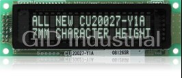
Noritake CU20027-Y100 Vacuum Fluorescent Display - Dot Graphic Module

Noritake CU20027-YX1A Vacuum Fluorescent - Dot Graphic Module
Noritake CU20029-KTW220A Dot Graphic VFD Module, 2 Line of 20 Characters 9mm High

Noritake CU20029-TE200K Vacuum Fluorescent Display - Dot Graphic Module
Noritake CU22042-Y1A Vacuum Fluoresent Display - Dot Graphic Module
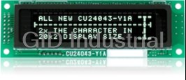
Noritake CU24043-Y100 Vacuum Fluorescent Display - Font Magnification
Request a Quote

The quote request has been received
Close

Facing challenges or have inquiries? Feel free to contact us!
Call Us +1-469-283-2440
What they say about us
FANTASTIC RESOURCE
One of our top priorities is maintaining our business with precision, and we are constantly looking for affiliates that can help us achieve our goal. With the aid of GID Industrial, our obsolete product management has never been more efficient. They have been a great resource to our company, and have quickly become a go-to supplier on our list!
Bucher Emhart Glass
EXCELLENT SERVICE
With our strict fundamentals and high expectations, we were surprised when we came across GID Industrial and their competitive pricing. When we approached them with our issue, they were incredibly confident in being able to provide us with a seamless solution at the best price for us. GID Industrial quickly understood our needs and provided us with excellent service, as well as fully tested product to ensure what we received would be the right fit for our company.
Fuji
HARD TO FIND A BETTER PROVIDER
Our company provides services to aid in the manufacture of technological products, such as semiconductors and flat panel displays, and often searching for distributors of obsolete product we require can waste time and money. Finding GID Industrial proved to be a great asset to our company, with cost effective solutions and superior knowledge on all of their materials, it’d be hard to find a better provider of obsolete or hard to find products.
Applied Materials
CONSISTENTLY DELIVERS QUALITY SOLUTIONS
Over the years, the equipment used in our company becomes discontinued, but they’re still of great use to us and our customers. Once these products are no longer available through the manufacturer, finding a reliable, quick supplier is a necessity, and luckily for us, GID Industrial has provided the most trustworthy, quality solutions to our obsolete component needs.
Nidec Vamco
TERRIFIC RESOURCE
This company has been a terrific help to us (I work for Trican Well Service) in sourcing the Micron Ram Memory we needed for our Siemens computers. Great service! And great pricing! I know when the product is shipping and when it will arrive, all the way through the ordering process.
Trican Well Service
GO TO SOURCE
When I can't find an obsolete part, I first call GID and they'll come up with my parts every time. Great customer service and follow up as well. Scott emails me from time to time to touch base and see if we're having trouble finding something.....which is often with our 25 yr old equipment.
ConAgra Foods