PHOTOCOUPLER
PS2701-1
HIGH ISOLATION VOLTAGE
−NEPOC Series−
SOP MULTI PHOTOCOUPLER
DESCRIPTION
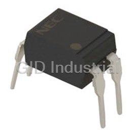
The PS2701-1 is an optically coupled isolator containing a GaAs light emitting diode and an NPN silicon
phototransistor.
This package is SOP (Small Outline Package) type and has shield effect to cut off ambient light.
It is designed for high density mounting applications.
FEATURES
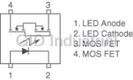
PIN CONNECTION
• High isolation voltage (BV = 3 750 Vr.m.s.)
(Top View)
• SOP (Small Outline Package) type
43
• High-speed switching (tr = 3 µs TYP., tf = 5 µs TYP.)
1. Anode
• Ordering number of taping product: PS2701-1-F3, F4
2. Cathode
• Safety standards
3. Emitter
4. Collector
• UL approved: No. E72422
12
• BSI approved: No. 8219/8220
• CSA approved: No. CA 101391
• DIN EN60747-5-2 (VDE0884 Part2) approved: No. 40008902 (Option)
APPLICATIONS
• Hybrid IC
• Measuring instruments
• Power supply
• Programmable logic controllers
Document No. PN10240EJ03V0DS (3rd edition)
Date Published December 2008 NS
1988, 2008
The mark shows major revised points.
The revised points can be easily searched by copying an "" in the PDF file and specifying it in the "Find what:" field.
PS2701-1
PACKAGE DIMENSIONS (in millimeters)
4.0±0.5
7.0±0.3
4.4
2.54
0.5±0.3
+0.10
0.4 0.25 M
–0.05
MARKING EXAMPLE
Pb-Free Special version (Pb-Free and Halogen Free)
Trade Mark Trade Mark
No. 1 pin Mark No. 1 pin Mark
2701 Type Number 2701 Type Number
M831 Assembly Lot M831 Assembly Lot
*1
*1
M8 31 M8 31
Week Assembled Week Assembled
Year Assembled Year Assembled
(Last 1 Digit) (Last 1 Digit)
CTR Rank Name CTR Rank Name
*1 Bar: Pb-Free *1 Bar: Pb-Free and Halogen Free
Remark "PS" and "-1" are omitted from original type number Remark "PS" and "-1" are omitted from original type number
2
Data Sheet PN10240EJ03V0DS
2.1±0.2
0.1±0.1 2.0
+0.10
0.15
–0.05
PS2701-1
ORDERING INFORMATION
Part Number Order Number Solder Plating Packing Style Safety Standard Application Part
*1
Specification Approval Number
PS2701-1 PS2701-1-A Pb-Free Magazine case 100 pcs Standard products PS2701-1
PS2701-1-F3 PS2701-1-F3-A Embossed Tape 3 500 pcs/reel (UL, BSI, CSA
PS2701-1-F4 PS2701-1-F4-A approved)
PS2701-1-V PS2701-1-V-A Magazine case 100 pcs DIN EN60747-5-2
PS2701-1-V-F3 PS2701-1-V-F3-A Embossed Tape 3 500 pcs/reel (VDE0884 Part2)
PS2701-1-V-F4 PS2701-1-V-F4-A Approved (Option)
PS2701-1 PS2701-1Y-A Special Magazine case 100 pcs Standard products PS2701-1
version
PS2701-1-F3 PS2701-1Y-F3-A (Pb-Free and Embossed Tape 3 500 pcs/reel (UL, BSI, CSA
Halogen Free) approved)
PS2701-1-V PS2701-1Y-V-A Magazine case 100 pcs DIN EN60747-5-2
PS2701-1-V-F3 PS2701-1Y-V-F3-A Embossed Tape 3 500 pcs/reel (VDE0884 Part2)
Approved (Option)
*1 For the application of the Safety Standard, following part number should be used.
3
Data Sheet PN10240EJ03V0DS
PS2701-1
ABSOLUTE MAXIMUM RATINGS (TA = 25°C, unless otherwise specified)
Parameter Symbol Ratings Unit
Diode Forward Current (DC) IF 50 mA
Reverse Voltage VR 6 V
Power Dissipation Derating ∆PD/°C 0.8 mW/°C
Power Dissipation PD 80 mW
*1
Peak Forward Current IFP 1 A
Transistor Collector to Emitter Voltage VCEO 40 V
Emitter to Collector Voltage VECO 6 V
Collector Current IC 80 mA
Power Dissipation Derating ∆PC/°C 1.5 mW/°C
Power Dissipation PC 150 mW
*2
Isolation Voltage BV 3 750 Vr.m.s.
Operating Ambient Temperature TA –55 to +100 °C
Storage Temperature Tstg –55 to +150 °C
*1 PW = 100 µs, Duty Cycle = 1%
*2 AC voltage for 1 minute at TA = 25°C, RH = 60% between input and output
Pins 1-2 shorted together, 3-4 shorted together.
4
Data Sheet PN10240EJ03V0DS
PS2701-1
ELECTRICAL CHARACTERISTICS (TA = 25°C)
Parameter Symbol Conditions MIN. TYP. MAX. Unit
Diode Forward Voltage VF IF = 5 mA 1.1 1.4 V
Reverse Current IR VR = 5 V 5 µA
Terminal Capacitance Ct V = 0 V, f = 1 MHz 30 pF
Collector to Emitter Dark
Transistor ICEO IF = 0 mA, VCE = 40 V 100 nA
Current
Coupled Current Transfer Ratio CTR IF = 5 mA, VCE = 5 V 50 100 300 %
*1
(IC/IF)
Collector Saturation
VCE (sat) IF = 10 mA, IC = 2 mA 0.3 V
Voltage
11
Isolation Resistance RI-O VI-O = 1 kVDC 10 Ω
Isolation Capacitance CI-O V = 0 V, f = 1 MHz 0.4 pF
*2
Rise Time tr VCC = 5 V, IC = 2 mA, RL = 100 Ω 3 µs
*2
Fall Time tf 5
*1 CTR rank
P: 150 to 300 (%)
L: 100 to 300 (%)
M: 50 to 150 (%)
*2 Test circuit for switching time
Pulse input VCC
Input
PW = 100 s, µ
Duty cycle = 1/10
ton
toff
IF td ts
VOUT
50 Ω RL = 100 Ω
90%
Output
10%
tr tf
5
Data Sheet PN10240EJ03V0DS
PS2701-1
TYPICAL CHARACTERISTICS (TA = 25°C, unless otherwise specified)
DIODE POWER DISSIPATION vs. TRANSISTOR POWER DISSIPATION vs.
AMBIENT TEMPERATURE AMBIENT TEMPERATURE
100 200
75 150
1.5 mW/°C
50 100
25 50
0 25 50 75 100 0 25 50 75 100
Ambient Temperature TA (°C) Ambient Temperature TA (°C)
FORWARD CURRENT vs. COLLECTOR CURRENT vs.
FORWARD VOLTAGE COLLECTOR TO EMITTER VOLTAGE
100 50
IF = 30 mA
40
TA = +100°C
10
+75°C
+50°C
20 mA
30
1
15 mA
+25°C
20
0°C
10 mA
–25°C
0.1 –55°C
10
5 mA
0.01
0.6 0.8 1.0 1.2 1.4 1.6 0 2461 8 0
Forward Voltage VF (V) Collector to Emitter Voltage VCE (V)
COLLECTOR TO EMITTER DARK COLLECTOR CURRENT vs.
CURRENT vs. AMBIENT TEMPERATURE COLLECTOR SATURATION VOLTAGE
10 000 50
IF = 25 mA
20
1 000 10 mA
VCE = 40 V
10
24 V
5 mA
10 V
5
100
2
2 mA
10
1
1 mA
0.5
1
0.2
0.1 0.1
–60 –40 –20 0 20 40 60 80 100 0.0 0.2 0.4 0.6 0.8 1.0
Collector Saturation Voltage VCE (sat) (V)
Ambient Temperature TA (°C)
Remark The graphs indicate nominal characteristics.
6
Data Sheet PN10240EJ03V0DS
Collector to Emitter Dark Current ICEO (nA)
Forward Current IF (mA) Diode Power Dissipation PD (mW)
Collector Current IC (mA) Collector Current IC (mA) Transistor Power Dissipation PC (mW)
PS2701-1
NORMALIZED CURRENT TRANSFER CURRENT TRANSFER RATIO vs.
RATIO vs. AMBIENT TEMPERATURE FORWARD CURRENT
1.2 300
VCE = 5 V
1.0 250
0.8 200
0.6 150
100
0.4
Normalized to 1.0
0.2 50
at TA = 25°C,
IF = 5 mA, VCE = 5 V
0
0.0
–50 –25 025 50 75 100 0.05 0.1 0.5 1 5 10 50
Ambient Temperature TA (°C) Forward Current IF (mA)
SWITCHING TIME vs.
LOAD RESISTANCE FREQUENCY RESPONSE
100 1.2
VCC = 5 V,
50 IC = 2 mA
1.0
ton
toff
RL = 1 kΩ
10
0.8
510 Ω
5
300 Ω
0.6
td
100 Ω
ts
1
0.4
0.5
0.2
0.1 0.0
50 100 200 500 1 k 2 k 2 5 10 20 50 100 200 500
Load Resistance RL (Ω) Frequency f (kHz)
SWITCHING TIME vs.
LOAD RESISTANCE LONG TERM CTR DEGRADATION
1 000 1.2
IF = 5 mA, VCC = 5 V,
tf
500
CTR = 169%
1.0
ts
100
50
0.8
IF = 1 mA, TA = 25°C
IF = 5 mA, TA = 25°C
0.6
10
IF = 20 mA, TA = 25°C
tr
5
IF = 20 mA, TA = 60°C
0.4
td
1
0.5
0.2
0.1
0.0
2 3 4 5 6
100 500 1 k 5 k 10 k 50 k 100 k
11 10 100 10 10
Load Resistance RL (Ω) Time (Hr)
Remark The graphs indicate nominal characteristics.
7
Data Sheet PN10240EJ03V0DS
Switching Time t ( s) µ Switching Time t ( s) µ Normalized Current Transfer Ratio CTR
CTR (Relative Value) Normalized Gain GV Current Transfer Ratio CTR (%)
PS2701-1
TAPING SPECIFICATIONS (in millimeters)
Outline and Dimensions (Tape)
2.0±0.05
4.0±0.1 +0.1 2.9 MAX.
1.5
–0
1.55±0.1
2.4±0.1
4.6±0.1
8.0±0.1 0.3
Tape Direction
PS2701-1-F3 PS2701-1-F4
Outline and Dimensions (Reel)
2.0±0.5
2.0±0.5
φ13.0±0.2
R 1.0
φ21.0±0.8
13.5±1.0
17.5±1.0
11.9 to 15.4
Outer edge of
Packing: 3 500 pcs/reel
flange
8
Data Sheet PN10240EJ03V0DS
5.5±0.05
1.75±0.1
12.0±0.2
φ330±2.0
7.4±0.1
φ100±1.0
φ13.0±0.2
PS2701-1
NOTES ON HANDLING
1. Recommended soldering conditions
(1) Infrared reflow soldering
• Peak reflow temperature 260°C or below (package surface temperature)
• Time of peak reflow temperature 10 seconds or less
• Time of temperature higher than 220°C 60 seconds or less
• Time to preheat temperature from 120 to 180°C 120±30 s
• Number of reflows Three
• Flux Rosin flux containing small amount of chlorine (The flux with a
maximum chlorine content of 0.2 Wt% is recommended.)
Recommended Temperature Profile of Infrared Reflow
(heating)
to 10 s
260°C MAX.
220°C
to 60 s
180°C
120°C
120±30 s
(preheating)
Time (s)
(2) Wave soldering
• Temperature 260°C or below (molten solder temperature)
• Time 10 seconds or less
• Preheating conditions 120°C or below (package surface temperature)
• Number of times One (Allowed to be dipped in solder including plastic mold portion.)
• Flux Rosin flux containing small amount of chlorine (The flux with a maximum chlorine
content of 0.2 Wt% is recommended.)
(3) Soldering by soldering iron
• Peak temperature (lead part temperature) 350°C or below
• Time (each pins) 3 seconds or less
• Flux Rosin flux containing small amount of chlorine (The flux with a
maximum chlorine content of 0.2 Wt% is recommended.)
(a) Soldering of leads should be made at the point 1.5 to 2.0 mm from the root of the lead.
(b) Please be sure that the temperature of the package would not be heated over 100°C.
9
Data Sheet PN10240EJ03V0DS
Package Surface Temperature T (°C)
PS2701-1
(4) Cautions
• Fluxes
Avoid removing the residual flux with freon-based and chlorine-based cleaning solvent.
2. Cautions regarding noise
Be aware that when voltage is applied suddenly between the photocoupler’s input and output or between
collector-emitters at startup, the output transistor may enter the on state, even if the voltage is within the absolute
maximum ratings.
3. Measurement conditions of current transfer ratios (CTR), which differ according to
photocoupler
Check the setting values before use, since the forward current conditions at CTR measurement differ according
to product.
When using products other than at the specified forward current, the characteristics curves may differ from the
standard curves due to CTR value variations or the like. This tendency may sometimes be obvious, especially
below IF = 1 mA.
Therefore, check the characteristics under the actual operating conditions and thoroughly take variations or the
like into consideration before use.
USAGE CAUTIONS
1. Protect against static electricity when handling.
2. Avoid storage at a high temperature and high humidity.
10
Data Sheet PN10240EJ03V0DS
PS2701-1
SPECIFICATION OF VDE MARKS LICENSE DOCUMENT
Parameter Symbol Spec. Unit
Climatic test class (IEC 60068-1/DIN EN 60068-1) 55/110/21
Dielectric strength
maximum operating isolation voltage UIORM peak
707 V
Upr Vpeak
Test voltage (partial discharge test, procedure a for type test and random test) 1 060
pr = 1.5 × UIORM, Pd < 5 pC
U
Test voltage (partial discharge test, procedure b for all devices) Upr 1 325 Vpeak
Upr = 1.875 × UIORM, Pd < 5 pC
Highest permissible overvoltage UTR 6 000 Vpeak
Degree of pollution (DIN EN 60664-1 VDE0110 Part 1) 2
Clearance distance >5.0 mm
Creepage distance >5.0 mm
Comparative tracking index (IEC 60112/DIN EN 60112 (VDE 0303 Part 11)) CTI 175
Material group (DIN EN 60664-1 VDE0110 Part 1) III a
Storage temperature range Tstg –55 to +150 °C
Operating temperature range TA –55 to +110 °C
Isolation resistance, minimum value
12
IO = 500 V dc at TA = 25°C
V Ris MIN. 10 Ω
11
IO = 500 V dc at TA MAX. at least 100°C
V Ris MIN. 10 Ω
Safety maximum ratings (maximum permissible in case of fault, see thermal
derating curve)
Package temperature Tsi 150 °C
Current (input current IF, Psi = 0) Isi 300 mA
Power (output or total power dissipation) Psi 500 mW
Isolation resistance
9
VIO = 500 V dc at TA = Tsi Ris MIN. 10 Ω
11
Data Sheet PN10240EJ03V0DS
PS2701-1
•
The information in this document is current as of December, 2008. The information is subject to
change without notice. For actual design-in, refer to the latest publications of NEC Electronics data
sheets or data books, etc., for the most up-to-date specifications of NEC Electronics products. Not
all products and/or types are available in every country. Please check with an NEC Electronics sales
representative for availability and additional information.
• No part of this document may be copied or reproduced in any form or by any means without the prior
written consent of NEC Electronics. NEC Electronics assumes no responsibility for any errors that may
appear in this document.
• NEC Electronics does not assume any liability for infringement of patents, copyrights or other intellectual
property rights of third parties by or arising from the use of NEC Electronics products listed in this document
or any other liability arising from the use of such products. No license, express, implied or otherwise, is
granted under any patents, copyrights or other intellectual property rights of NEC Electronics or others.
• Descriptions of circuits, software and other related information in this document are provided for illustrative
purposes in semiconductor product operation and application examples. The incorporation of these
circuits, software and information in the design of a customer's equipment shall be done under the full
responsibility of the customer. NEC Electronics assumes no responsibility for any losses incurred by
customers or third parties arising from the use of these circuits, software and information.
• While NEC Electronics endeavors to enhance the quality, reliability and safety of NEC Electronics products,
customers agree and acknowledge that the possibility of defects thereof cannot be eliminated entirely. To
minimize risks of damage to property or injury (including death) to persons arising from defects in NEC
Electronics products, customers must incorporate sufficient safety measures in their design, such as
redundancy, fire-containment and anti-failure features.
• NEC Electronics products are classified into the following three quality grades: "Standard", "Special" and
"Specific".
The "Specific" quality grade applies only to NEC Electronics products developed based on a customer-
designated "quality assurance program" for a specific application. The recommended applications of an NEC
Electronics product depend on its quality grade, as indicated below. Customers must check the quality grade of
each NEC Electronics product before using it in a particular application.
"Standard": Computers, office equipment, communications equipment, test and measurement equipment, audio
and visual equipment, home electronic appliances, machine tools, personal electronic equipment
and industrial robots.
"Special": Transportation equipment (automobiles, trains, ships, etc.), traffic control systems, anti-disaster
systems, anti-crime systems, safety equipment and medical equipment (not specifically designed
for life support).
"Specific": Aircraft, aerospace equipment, submersible repeaters, nuclear reactor control systems, life
support systems and medical equipment for life support, etc.
The quality grade of NEC Electronics products is "Standard" unless otherwise expressly specified in NEC
Electronics data sheets or data books, etc. If customers wish to use NEC Electronics products in applications
not intended by NEC Electronics, they must contact an NEC Electronics sales representative in advance to
determine NEC Electronics' willingness to support a given application.
(Note)
(1)
"NEC Electronics" as used in this statement means NEC Electronics Corporation and also includes its
majority-owned subsidiaries.
(2)
"NEC Electronics products" means any product developed or manufactured by or for NEC Electronics (as
defined above).
M8E 02. 11-1
12
Data Sheet PN10240EJ03V0DS
PS2701-1
This product uses gallium arsenide (GaAs).
Caution GaAs Products
GaAs vapor and powder are hazardous to human health if inhaled or ingested, so please observe
the following points.
• Follow related laws and ordinances when disposing of the product. If there are no applicable laws
and/or ordinances, dispose of the product as recommended below.
1. Commission a disposal company able to (with a license to) collect, transport and dispose of
materials that contain arsenic and other such industrial waste materials.
2. Exclude the product from general industrial waste and household garbage, and ensure that the
product is controlled (as industrial waste subject to special control) up until final disposal.
• Do not burn, destroy, cut, crush, or chemically dissolve the product.
• Do not lick the product or in any way allow it to enter the mouth.


 Manufacturers














What they say about us
FANTASTIC RESOURCE
One of our top priorities is maintaining our business with precision, and we are constantly looking for affiliates that can help us achieve our goal. With the aid of GID Industrial, our obsolete product management has never been more efficient. They have been a great resource to our company, and have quickly become a go-to supplier on our list!
Bucher Emhart Glass
EXCELLENT SERVICE
With our strict fundamentals and high expectations, we were surprised when we came across GID Industrial and their competitive pricing. When we approached them with our issue, they were incredibly confident in being able to provide us with a seamless solution at the best price for us. GID Industrial quickly understood our needs and provided us with excellent service, as well as fully tested product to ensure what we received would be the right fit for our company.
Fuji
HARD TO FIND A BETTER PROVIDER
Our company provides services to aid in the manufacture of technological products, such as semiconductors and flat panel displays, and often searching for distributors of obsolete product we require can waste time and money. Finding GID Industrial proved to be a great asset to our company, with cost effective solutions and superior knowledge on all of their materials, it’d be hard to find a better provider of obsolete or hard to find products.
Applied Materials
CONSISTENTLY DELIVERS QUALITY SOLUTIONS
Over the years, the equipment used in our company becomes discontinued, but they’re still of great use to us and our customers. Once these products are no longer available through the manufacturer, finding a reliable, quick supplier is a necessity, and luckily for us, GID Industrial has provided the most trustworthy, quality solutions to our obsolete component needs.
Nidec Vamco
TERRIFIC RESOURCE
This company has been a terrific help to us (I work for Trican Well Service) in sourcing the Micron Ram Memory we needed for our Siemens computers. Great service! And great pricing! I know when the product is shipping and when it will arrive, all the way through the ordering process.
Trican Well Service
GO TO SOURCE
When I can't find an obsolete part, I first call GID and they'll come up with my parts every time. Great customer service and follow up as well. Scott emails me from time to time to touch base and see if we're having trouble finding something.....which is often with our 25 yr old equipment.
ConAgra Foods