

 Manufacturers
MOLEX 0039012080

Description
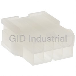
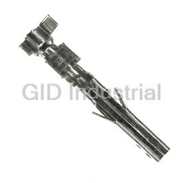
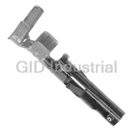
Molex 0039012080 Connector Receptacle. Mini-Fit Jr 5557 Series | Female Socket | 8 Position | Dual 2x4
Part Number
0039012080
Price
Request Quote
Manufacturer
MOLEX
Lead Time
Request Quote
Category
PRODUCTS - W
Specifications
Color
Natural
Connector Type
Receptacle
Contact Termination
Crimp
Contact Type
Female Socket
Fastening Type
Latch Lock
Lead Free Status
Lead Free
Mounting Type
Free Hanging (In-Line)
Number of Positions
8
Number of Rows
2
Packaging
Bulk
Pitch
0.165" (4.20mm)
RoHS Status
RoHS Compliant
Row Spacing
0.165" (4.20mm)
Datasheet

Extracted Text
PRODUCT SPECIFICATION MINI-FIT JR. Table of Contents Section Page 1.0 Scope 2 2.0 Product Description 2 2.1 Names and Series Number(s) 2 Table 1 – Wire-To-Wire 2 Table 2 – Wire-To-Board 2 2.2 Dimensions, Materials, Platings, and Markings 2 2.3 Safety Agency Approvals 2 3.0 Applicable Documents and Specifications 2 4.0 Ratings 3 4.1 Voltage 3 4.2 Applicable Wires 3 4.3 Maximum Current Rating (Amperes) 3 Table 3 – Maximum Current Rating (Amperes) Wire-To-Wire and Wire-To-Board 3 4.4 Temperature 3 4.5 Wave Solder Process Temperature 3 5.0 Wire-To-Wire Performance 4 5.1 Electrical Requirements 4 5.2 Mechanical Requirements 4 5.3 Environmental Requirements 6 6.0 Wire-To-Board Performance 7 6.1 Electrical Requirements 7 6.2 Mechanical Requirements 7 6.3 Environmental Requirements 9 7.0 Test Sequences 9 8.0 Packaging 9 REVISION: ECR/ECN INFORMATION: TITLE: SHEET No. PRODUCT SPECIFICATION FOR EC No: UCP2010-3155 MINI-FIT JR. 1 of 9 E5 DATE: 2010/06/10 CONNECTOR SYSTEM DOCUMENT NUMBER: CREATED / REVISED BY: CHECKED BY: APPROVED BY: JJAGUILAR JBELL FSMITH PS-5556-001 TEMPLATE FILENAME: PRODUCT_SPEC[SIZE_A](V.1).DOC PRODUCT SPECIFICATION 1.0 SCOPE This Product Specification covers performance requirements for the MINI-FIT JR. 4.20 mm (.165 inch) centerline (pitch) printed circuit board (PCB) connector series with Tin or Gold plating, and The MINI-FIT JR. connector series terminated with 16 to 28 AWG wire using Crimp technology with Tin or Gold plating. 2.0 PRODUCT DESCRIPTION 2.1 PRODUCT NAME AND SERIES NUMBER (S) Table 1 – WIRE-TO-WIRE Description Series Number RoHS UL CSA TUV Female Crimp Terminal 5556 Yes n/a n/a n/a Receptacle Housing 5557 Yes Yes Yes Yes Male Crimp Terminal 5558 Yes n/a n/a n/a Plug Housing 5559 Yes Yes Yes Yes Table 2 – WIRE-TO-BOARD Description Series Number RoHS UL CSA TUV Female Crimp Terminal 5556 Yes n/a n/a n/a Receptacle Housing 5557 Yes Yes Yes Yes Vertical Header 5566 Yes Yes Yes Yes Right Angle Header 5569 Yes Yes Yes Yes 2.2 DIMENSIONS, MATERIALS, PLATINGS AND MARKINGS See the appropriate sales drawings for the information on dimensions, materials, platings and markings. 2.3 SAFETY AGENCY APPROVALS UL File: E29179 CSA Certificate: LR 19980 TUV Certificate: R72081037 3.0 APPLICABLE DOCUMENTS AND SPECIFICATIONS See sales drawings and the other sections of this specification for the necessary referenced documents and specifications. REVISION: ECR/ECN INFORMATION: TITLE: SHEET No. PRODUCT SPECIFICATION FOR EC No: UCP2010-3155 MINI-FIT JR. 2 of 9 E5 DATE: 2010/06/10 CONNECTOR SYSTEM DOCUMENT NUMBER: CREATED / REVISED BY: CHECKED BY: APPROVED BY: JJAGUILAR JBELL FSMITH PS-5556-001 TEMPLATE FILENAME: PRODUCT_SPEC[SIZE_A](V.1).DOC PRODUCT SPECIFICATION 4.0 RATINGS 4.1 VOLTAGE 600 Volts AC (RMS) (or 600 Volts DC) 4.2 APPLICABLE WIRES 16 AWG: 3.10 mm / .122 inches MAXIMUM Maximum Insulation Diameter and 18-24 AWG: 3.10 mm / .122 inches MAXIMUM Applicable Wire Gauges 22-28 AWG: 1.80 mm / .071 inches MAXIMUM 4.3 MAXIMUM CURRENT RATING (Amperes) Table 3 - MAXIMUM CURRENT RATING (Amperes) Wire-to-Wire and Wire-to-Board Brass Phosphor Bronze Ckt. Size Ckt. Size 2 & 3 4 - 6 7 - 10 12 - 24 2 & 3 4 - 6 7 - 10 12 - 24 Wire Wire AWG #16 9 8 7 6 AWG #16 8 7 6 5 AWG #18 9 8 7 6 AWG #18 8 7 6 5 AWG #20 7 6 5 5 AWG #20 6 5 4 4 AWG #22 5 4 4 4 AWG #22 4 3 3 3 AWG #24 4 3 3 3 AWG #24 3 2 2 2 AWG #26 3 2 2 2 AWG #26 2 1 1 1 AWG #28 2 1 1 1 AWG #28 1 1 1 1 Note: PCB trace design may greatly affect temperature rise results in Wire-to-Board Applications. 4.4 TEMPERATURE Operating: * - 40°C to + 105°C Nonoperating: - 40°C to + 105°C *Including 30°C terminal temperature at rated current 4.5 WAVE SOLDER PROCESS TEMPERATURE Headers with pegs: 240°C Maximum Headers without pegs: 260°C Maximum REVISION: ECR/ECN INFORMATION: TITLE: SHEET No. PRODUCT SPECIFICATION FOR EC No: UCP2010-3155 MINI-FIT JR. 3 of 9 E5 DATE: 2010/06/10 CONNECTOR SYSTEM DOCUMENT NUMBER: CREATED / REVISED BY: CHECKED BY: APPROVED BY: JJAGUILAR JBELL FSMITH PS-5556-001 TEMPLATE FILENAME: PRODUCT_SPEC[SIZE_A](V.1).DOC PRODUCT SPECIFICATION 5.0 WIRE-TO-WIRE PERFORMANCE 5.1 ELECTRICAL REQUIREMENTS ITEM DESCRIPTION TEST CONDITION REQUIREMENT Mate connectors: apply a maximum Contact 10 milliohms voltage of 20 mV and a current of 100 Resistance MAXIMUM 1 mA. Wire resistance shall be removed (Low Level) [initial] from the measured value. Contact 10 milliohms Mate connectors: apply a maximum 2 Resistance MAXIMUM voltage of 20 mV at rated current. @ Rated Current [initial] Contact Terminate the applicable wire to the 5 milliohms Resistance of terminal and measure wire using a MAXIMUM 3 Wire Termination voltage of 20 mV and a current of 100 [initial] (Low Level) mA. Mate connectors: apply a voltage of 500 Insulation 1000 Megohms 4 VDC between adjacent terminals and Resistance MINIMUM between terminals to ground. Mate connectors: apply a voltage of Dielectric 1500 VAC for 1 minute between No breakdown. Withstanding 5 adjacent terminals and between Current leakage < 5 mA Voltage terminals to ground. Mate connectors. Measure the temperature rise at the rated current Temperature Rise after 96 hours, during current cycling (45 Temperature rise: 6 (via Current minutes ON and 15 minutes OFF per +30°C MAXIMUM Cycling) hour) for 240 hours, and after final 96- hour steady state. 5.2 MECHANICAL REQUIREMENTS ITEM DESCRIPTION TEST CONDITION REQUIREMENT 14.7 N (3.30 lbf) Terminal Mate Insert and withdraw terminal (male to MAXIMUM insertion force and 1 female) at a rate of 25 ± 6 mm (1 ± ¼ and Unmate Forces inch) per minute. 0.5 N (0.11 lbf) Per Circuit MINIMUM withdrawal force Crimp Terminal Axial pullout force on the terminal in the 30 N (6.74 lbf) 2 Retention Force housing at a rate of 25 ± 6 mm (1 ± ¼ MINIMUM retention force (in Housing) inch) per minute. Mate connectors up to 30 cycles at a 3 Durability maximum rate of 10 cycles per minute 20 milliohms MAXIMUM prior to Environmental Tests. REVISION: ECR/ECN INFORMATION: TITLE: SHEET No. PRODUCT SPECIFICATION FOR EC No: UCP2010-3155 MINI-FIT JR. 4 of 9 E5 DATE: 2010/06/10 CONNECTOR SYSTEM DOCUMENT NUMBER: CREATED / REVISED BY: CHECKED BY: APPROVED BY: JJAGUILAR JBELL FSMITH PS-5556-001 TEMPLATE FILENAME: PRODUCT_SPEC[SIZE_A](V.1).DOC PRODUCT SPECIFICATION 5.2 MECHANICAL REQUIREMENTS (continued) ITEM DESCRIPTION TEST CONDITION REQUIREMENT 10 milliohms MAXIMUM Vibration Mate connectors and vibrate per EIA (change from initial) 4 (Random) 364-28, test condition VII. and Discontinuity < 1 microsecond Mate connectors and shock at 50 g's 20 milliohms MAXIMUM Shock with ½ sine wave (11 milliseconds) 5 and (Mechanical) shocks in the ±X, ±Y, ±Z axes, (18 Discontinuity < 1 microsecond shocks total). 16 Awg = 88.0 N (19.8 lbf) Min. 18 Awg = 88.0 N (19.8 lbf) Min. Wire 20 Awg = 59.0 N (13.3 lbf) Min. Apply an axial pullout force on the wire 6 Pullout Force 22 Awg = 39.0 N (8.78 lbf) Min. at a rate of 25 ± 6 mm (1 ± ¼ inch). (Axial) 24 Awg = 29.0 N (6.52 lbf) Min. 26 Awg = 19.0 N (4.27 lbf) Min. 28 Awg = 9.80 N (2.20 lbf) Min. Crimp Terminal Apply an axial insertion force on the 15.0 N (3.37 lbf) 7 Insertion Force terminal at a rate of 25 ± 6 mm (1 ± ¼ MAXIMUM insertion force (into Housing) inch). 1.47 N (150 grams) Sn Normal MINIMUM 8 Apply a perpendicular force. Force 0.49 N (50 grams) Au MINIMUM 225 N (50.7 lbf) Insert and withdraw a connector at a MAXIMUM insertion force Panel Insertion and rate of 25 ± 6 mm (1 ± ¼ inch) per 9 and Withdrawl Forces minute. (Applies only to plugs with 157 N (35.3 lbf) MINIMUM panel retention feature) withdrawl force Thumblatch Depress latch at a speed rate of 25 ± 6 10 16.67 N (3.75 lbf) MAXIMUM Operation Force mm (1 ± ¼ inch) per minute. Mate loaded connectors fully. Pull Thumblatch Yield 68 N (15.3 lbf) MINIMUM 11 connectors apart at a speed rate of 25 ± Strength 6 mm (1 ± ¼ inch) per minute. REVISION: ECR/ECN INFORMATION: TITLE: SHEET No. PRODUCT SPECIFICATION FOR EC No: UCP2010-3155 MINI-FIT JR. 5 of 9 E5 DATE: 2010/06/10 CONNECTOR SYSTEM DOCUMENT NUMBER: CREATED / REVISED BY: CHECKED BY: APPROVED BY: JJAGUILAR JBELL FSMITH PS-5556-001 TEMPLATE FILENAME: PRODUCT_SPEC[SIZE_A](V.1).DOC PRODUCT SPECIFICATION 5.3 ENVIRONMENTAL REQUIREMENTS ITEM DESCRIPTION TEST CONDITION REQUIREMENT 20 milliohms MAXIMUM Mate connectors: expose for 5 cycles Thermal Visual: No Damage 1 Between temperatures –55 and 105° C; Shock Dielectric Strength per 5.1.5 Dwell 0.5 hours at each temperature. Insulation Resistance per 5.1.4 20 milliohms MAXIMUM Mate connectors; expose to: 2 Thermal Aging and 96 hours at 105 ± 2°C Visual: No Damage 20 milliohms MAXIMUM Mate connectors: expose to a Humidity Visual: No Damage 3 temperature of 60 ± 2°C with a relative (Steady State) Dielectric Strength per 5.1.5 humidity of 90-95% for 96 hours. Insulation Resistance per 5.1.4 Mate connectors: 20 milliohms MAXIMUM 4 Cold Resistance Duration: 96 hours; and Temperature: -40 ± 3°C Visual: No Damage Mate connectors: Corrosive Duration: 24 hours exposure. 20 milliohms MAXIMUM Atmosphere: Sulfur 5 Atmosphere: 50 parts per million (ppm) and Dioxide Gas SO Gas. Visual: No Damage 2 (SO ) 2 Temperature: 40 ± 3°C REVISION: ECR/ECN INFORMATION: TITLE: SHEET No. PRODUCT SPECIFICATION FOR EC No: UCP2010-3155 MINI-FIT JR. 6 of 9 E5 DATE: 2010/06/10 CONNECTOR SYSTEM DOCUMENT NUMBER: CREATED / REVISED BY: CHECKED BY: APPROVED BY: JJAGUILAR JBELL FSMITH PS-5556-001 TEMPLATE FILENAME: PRODUCT_SPEC[SIZE_A](V.1).DOC PRODUCT SPECIFICATION 6.0 WIRE-TO-BOARD PERFORMANCE 6.1 ELECTRICAL REQUIREMENTS ITEM DESCRIPTION TEST CONDITION REQURIEMENT Mate connectors: apply a maximum Contact 10 milliohms voltage of 20 mV and a current of 100 Resistance MAXIMUM 1 mA. Wire resistance shall be removed (Low Level) [initial] from the measured value. Contact 10 milliohms Mate connectors: apply a maximum 2 Resistance MAXIMUM voltage of 20 mV at rated current. @ Rated Current [initial] Contact Terminate the applicable wire to the 5 milliohms Resistance of terminal and measure wire using a MAXIMUM 3 Wire Termination voltage of 20 mV and a current of 100 [initial] (Low Level) mA. Mate connectors: apply a voltage of 500 Insulation 1000 Megohms 4 VDC between adjacent terminals and Resistance MINIMUM between terminals to ground. Mate connectors: apply a voltage of Dielectric 1500 VAC for 1 minute between No breakdown. Withstanding 5 adjacent terminals and between Current leakage < 5 mA Voltage terminals to ground. Mate connectors. Measure the Temperature Rise temperature rise at the rated current (via Current after 96 hours, during current cycling (45 Temperature rise: 6 Cycling) minutes ON and 15 minutes OFF per +30°C MAXIMUM hour) for 240 hours, and after final 96- hour steady state. 6.2 MECHANICAL REQUIREMENTS ITEM DESCRIPTION TEST CONDITION REQUIREMENT 14.7 N (3.30 lbf) Terminal Mate Insert and withdraw terminal (male to MAXIMUM insertion force and female) at a rate of 25 ± 6 mm (1 ± ¼ and 1 Unmate Forces inch) per minute. 0.5 N (0.11 lbf) Per Circuit MINIMUM withdrawal force Crimp Terminal Axial pullout force on the terminal in the 30 N (6.74 lbf) 2 Retention Force housing at a rate of 25 ± 6 mm (1 ± ¼ MINIMUM retention force (in Housing) inch) per minute. Mate connectors up to 30 cycles at a Durability maximum rate of 10 cycles per minute 20 milliohms MAXIMUM 3 prior to Environmental Tests. REVISION: ECR/ECN INFORMATION: TITLE: SHEET No. PRODUCT SPECIFICATION FOR EC No: UCP2010-3155 MINI-FIT JR. 7 of 9 E5 DATE: 2010/06/10 CONNECTOR SYSTEM DOCUMENT NUMBER: CREATED / REVISED BY: CHECKED BY: APPROVED BY: JJAGUILAR JBELL FSMITH PS-5556-001 TEMPLATE FILENAME: PRODUCT_SPEC[SIZE_A](V.1).DOC PRODUCT SPECIFICATION 6.2 MECHANICAL REQUIREMENTS (continued) ITEM DESCRIPTION TEST CONDITION REQUIREMENT 10 milliohms MAXIMUM Vibration Mate connectors and vibrate per EIA 364-28, (change from initial) 4 (Random) test condition VII. and Discontinuity < 1 microsecond Mate connectors and shock at 50 g's with ½ 20 milliohms MAXIMUM Shock 5 sine wave (11 milliseconds) shocks in the and (Mechanical) ±X, ±Y, ±Z axes, (18 shocks total). Discontinuity < 1 microsecond 16 Awg = 88.0 N (19.8 lbf) Min. 18 Awg = 88.0 N (19.8 lbf) Min. Wire 20 Awg = 59.0 N (13.3 lbf) Min. Apply an axial pullout force on the wire at a 6 Pullout Force 22 Awg = 39.0 N (8.78 lbf) Min. rate of 25 ± 6 mm (1 ± ¼ inch). (Axial) 24 Awg = 29.0 N (6.52 lbf) Min. 26 Awg = 19.0 N (4.27 lbf) Min. 28 Awg = 9.80 N (2.20 lbf) Min. Crimp Terminal Apply an axial insertion force on the terminal 15.0 N (3.37 lbf) 7 Insertion Force at a rate of 25 ± 6 mm (1 ± ¼ inch). MAXIMUM insertion force (into Housing) 1.47 N (150 grams) Sn MINIMUM Normal 8 Apply a perpendicular force. Force 0.49 N (50 grams) Au MINIMUM 49.0 N (11.0 lbf) Engage and separate a connector at a rate PCB Engagement MAXIMUM insertion force of 25 ± 6 mm (1 ± ¼ inch) per minute. and and 9 (Applies to parts with PCB retention features Separation Forces 10.0 N (2.24 lbf) only) MINIMUM withdrawal force Apply axial push force at the speed rate of 9.81 N (2.20 lbf) MINIMUM 10 Pin Retention Force 25 ± 3mm/minute. RETENTION FORCE Thumblatch Depress latch at a speed rate of 25 ± 6 mm 11 16.67 N (3.75 lbf) MAXIMUM Operation Force (1 ± ¼ inch) per minute. Mate loaded connectors fully. Pull Thumblatch Yield 12 connectors apart at a speed rate of 25 ± 6 68 N (15.3 lbf) MINIMUM Strength mm (1 ± ¼ inch) per minute. REVISION: ECR/ECN INFORMATION: TITLE: SHEET No. PRODUCT SPECIFICATION FOR EC No: UCP2010-3155 MINI-FIT JR. 8 of 9 E5 DATE: 2010/06/10 CONNECTOR SYSTEM DOCUMENT NUMBER: CREATED / REVISED BY: CHECKED BY: APPROVED BY: JJAGUILAR JBELL FSMITH PS-5556-001 TEMPLATE FILENAME: PRODUCT_SPEC[SIZE_A](V.1).DOC PRODUCT SPECIFICATION 6.3 ENVIRONMENTAL REQUIREMENTS ITEM DESCRIPTION TEST CONDITION REQUIREMENT 20 milliohms MAXIMUM Mate connectors: expose for 5 cycles Thermal Visual: No Damage 1 Between temperatures –55 and 105° C; Shock Dielectric Strength per 6.1.5 Dwell 0.5 hours at each temperature. Insulation Resistance per 6.1.4 20 milliohms MAXIMUM Mate connectors; expose to: 2 Thermal Aging and 96 hours at 105 ± 2°C Visual: No Damage 20 milliohms MAXIMUM Mate connectors: expose to a temperature Humidity Visual: No Damage of 60 ± 2°C with a relative humidity of 90- 3 (Steady State) Dielectric Strength per 6.1.5 95% for 96 hours. Insulation Resistance per 6.1.4 Solder coverage: Solderability Per SMES-152 95% MINIMUM 4 (per SMES-152) Dip connector terminals tail in solder: Visual: Solder Solder Duration: 5 ± 0.5 seconds; No Damage to insulator 5 Resistance Solder Temperature: 260 ± 5°C material Mate connectors: 20 milliohms MAXIMUM Cold Resistance Duration; 96 hours; and 6 Temperature: -40 ± 3°C Visual: No Damage Mate connectors: Corrosive Duration; 24 hours exposure. 20 milliohms MAXIMUM Atmosphere: Sulfur 7 Atmosphere: 50 parts per million (ppm) SO and 2 Dioxide Gas Gas. Visual: No Damage (SO ) 2 Temperature: 40 ± 3°C 7.0 TEST SEQUENCES Testing sequences to be performed in accordance with EIA-364-1000.01 8.0 PACKAGING Parts shall be packaged to protect against damage during handling, transit and storage. REVISION: ECR/ECN INFORMATION: TITLE: SHEET No. PRODUCT SPECIFICATION FOR EC No: UCP2010-3155 MINI-FIT JR. 9 of 9 E5 DATE: 2010/06/10 CONNECTOR SYSTEM DOCUMENT NUMBER: CREATED / REVISED BY: CHECKED BY: APPROVED BY: JJAGUILAR JBELL FSMITH PS-5556-001 TEMPLATE FILENAME: PRODUCT_SPEC[SIZE_A](V.1).DOC
Frequently asked questions
What makes Elite.Parts unique?

What kind of warranty will the 0039012080 have?
Which carriers does Elite.Parts work with?
Will Elite.Parts sell to me even though I live outside the USA?
I have a preferred payment method. Will Elite.Parts accept it?
Why buy from GID?

Quality
We are industry veterans who take pride in our work

Protection
Avoid the dangers of risky trading in the gray market

Access
Our network of suppliers is ready and at your disposal

Savings
Maintain legacy systems to prevent costly downtime

Speed
Time is of the essence, and we are respectful of yours
Related Products

Potter & Brumfield/Tyco / WaldomCKTBKR,MAG,LEVER,S
FIBER WALL MOUNT 6P ST MM BOX-WHITE
Molex WM23603-ND Connector Plug. Mini-Fit Jr 5559 Series | Panel Mount | Male Plug | 8 Position | Du...
Molex WM3114CT-ND Connector Terminal. Mini-Fit Jr 5556 Series | Female | 16AWG | Tin | Crimp
Molex WM3114CT-ND Connector Terminal. Mini-Fit Jr 5558 Series | Male | 16AWG | Tin | Crimp
Request a Quote

The quote request has been received
Close

Facing challenges or have inquiries? Feel free to contact us!
Call Us +1-469-283-2440
What they say about us
FANTASTIC RESOURCE
One of our top priorities is maintaining our business with precision, and we are constantly looking for affiliates that can help us achieve our goal. With the aid of GID Industrial, our obsolete product management has never been more efficient. They have been a great resource to our company, and have quickly become a go-to supplier on our list!
Bucher Emhart Glass
EXCELLENT SERVICE
With our strict fundamentals and high expectations, we were surprised when we came across GID Industrial and their competitive pricing. When we approached them with our issue, they were incredibly confident in being able to provide us with a seamless solution at the best price for us. GID Industrial quickly understood our needs and provided us with excellent service, as well as fully tested product to ensure what we received would be the right fit for our company.
Fuji
HARD TO FIND A BETTER PROVIDER
Our company provides services to aid in the manufacture of technological products, such as semiconductors and flat panel displays, and often searching for distributors of obsolete product we require can waste time and money. Finding GID Industrial proved to be a great asset to our company, with cost effective solutions and superior knowledge on all of their materials, it’d be hard to find a better provider of obsolete or hard to find products.
Applied Materials
CONSISTENTLY DELIVERS QUALITY SOLUTIONS
Over the years, the equipment used in our company becomes discontinued, but they’re still of great use to us and our customers. Once these products are no longer available through the manufacturer, finding a reliable, quick supplier is a necessity, and luckily for us, GID Industrial has provided the most trustworthy, quality solutions to our obsolete component needs.
Nidec Vamco
TERRIFIC RESOURCE
This company has been a terrific help to us (I work for Trican Well Service) in sourcing the Micron Ram Memory we needed for our Siemens computers. Great service! And great pricing! I know when the product is shipping and when it will arrive, all the way through the ordering process.
Trican Well Service
GO TO SOURCE
When I can't find an obsolete part, I first call GID and they'll come up with my parts every time. Great customer service and follow up as well. Scott emails me from time to time to touch base and see if we're having trouble finding something.....which is often with our 25 yr old equipment.
ConAgra Foods