

 Manufacturers
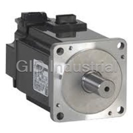
MITSUBISHI HCKFS73
Description
Mitsubishi HCKFS73 Servo Motor - Low Inertia, Small Capacity 200V
Part Number
HCKFS73
Price
Request Quote
Manufacturer
MITSUBISHI
Lead Time
Request Quote
Category
SERVO MOTORS
Specifications
Rated Output Capacity [kW]
0.75
Rated Speed [r/min]
3000
Datasheet

Extracted Text
MITSUBISHIELECTRIC ServoAmplifiers andServoMotors MELSERVO MR-J2-SUPER TechnicalCatalogue 2005 ServoIntelligence:MR-J2SSeries Mitsubishiintroducesthenewgeneral-purpose400VACservo amplifiersMR-J2S-A4, MR-J2S-B4andthecorrespondingHC-SFS andHA-LFSseries400VACservomotors. Thenewservoamplifiersareavailableinversionswithoutput ratingsfrom600Wto7kW. Inadditionacompleteline-upof400Vproductsupto55kWis availableonrequest. FurtherPublicationswithintheFactoryAutomationRange Inverter Technical Catalogues Product catalogues for the frequency inverters FR-A 540 (L-G), FR-E 500, FR-F 700 and FR-S 500E, control panels, and accessories Motion Controller Technical Catalogue Product catalogues for motion controllers of the MELSEC A and the MELSEC System Q series, motion control software and accessories PLC Technical Catalogues Product catalogues for programmable logic controllers and accessories for the MELSEC series Networks Technical Catalogue Product catalogue for Master and Slave modules as well as accessories for the use of programmable logic controllers in open networks and MELSEC networks HMI Technical Catalogue Product catalogue for operator terminals, process visualisation and programming software as well as accessories AdditionalServices You will find current information on updates, alterations, new items and technical support on MITSUBISHI ELECTRIC's web pages (www.mitsubishi-automation.com). The products section of the MITSUBISHI home site includes various documents for the whole product range offered by MITSUBISHI ELECTRIC as well as the current version of this catalogue. All manuals and catalogues can be downloaded for your convenience. Manuals and catalogues are available in multiple language. Please check for availability. Aboutthisproductcatalogue Due to the constantly growing product range, technical alteration, and new or changed characteristical features, this catalogue is updated frequently. Texts,figuresanddiagramsshowninthisproductcatalogueareintendedexclusivelyforexplanationandassistanceinplanningandorderingthe servomotorsandamplifiersoftheMELSERVOseriesandassociatedaccessories.Onlythemanualssuppliedwiththeunitsarerelevantforinstallation, commissioningandhandlingoftheunitsandaccessories.Theinformationgiveninthesedocumentationsmustbereadbeforeinstallationandcom- missioningoftheunitsorsoftware. Should questions arise with regard to the planning of modules described in this product catalogue, do not hesitate to contact your nearest office listed on the last page of this document. © MITSUBISHI ELECTRIC EUROPE B.V. 04/2005 (7th edition) 2 MELSERVOMR-J2S MITSUBISHIELECTRIC New Products Technical Catalogues CONTENTS MELSERVOMR-J2SSERIES–SERVOAMPLIFIERSANDSERVOMOTORS SYSTEMDESCRIPTION � Servo and motion systems . . . . . . . . . . . . . . . . . . . . . . . . . . . . . . . . . . . . . . . . . . . . . . . . . . . . . . . . . . . . . . . . . . . . . . . . . . . . . . . . 4 � Introduction to the MELSERVO series and overview of all features . . . . . . . . . . . . . . . . . . . . . . . . . . . . . . . . . . . . . . . . . . 5 � Description of the MR-J2S servo amplifiers . . . . . . . . . . . . . . . . . . . . . . . . . . . . . . . . . . . . . . . . . . . . . . . . . . . . . . . . . . . . . . . . . 7 � Control functions and enhanced tuning technology. . . . . . . . . . . . . . . . . . . . . . . . . . . . . . . . . . . . . . . . . . . . . . . . . . . . . . . . 8 � Software and handling . . . . . . . . . . . . . . . . . . . . . . . . . . . . . . . . . . . . . . . . . . . . . . . . . . . . . . . . . . . . . . . . . . . . . . . . . . . . . . . . . . . . 9 � Servo motor and servo amplifier model designations. . . . . . . . . . . . . . . . . . . . . . . . . . . . . . . . . . . . . . . . . . . . . . . . . . . . . . 10 SERVOMOTORS � Description of the servo motors . . . . . . . . . . . . . . . . . . . . . . . . . . . . . . . . . . . . . . . . . . . . . . . . . . . . . . . . . . . . . . . . . . . . . . . . . . 12 � Servo motor specifications and matching amplifiers . . . . . . . . . . . . . . . . . . . . . . . . . . . . . . . . . . . . . . . . . . . . . . . . . . . . . . 13 � Specifications and torque characteristics . . . . . . . . . . . . . . . . . . . . . . . . . . . . . . . . . . . . . . . . . . . . . . . . . . . . . . . . . . . . . . . . . 14 � Braked motor specifications. . . . . . . . . . . . . . . . . . . . . . . . . . . . . . . . . . . . . . . . . . . . . . . . . . . . . . . . . . . . . . . . . . . . . . . . . . . . . . 19 SERVOAMPLIFIERS � Specifications . . . . . . . . . . . . . . . . . . . . . . . . . . . . . . . . . . . . . . . . . . . . . . . . . . . . . . . . . . . . . . . . . . . . . . . . . . . . . . . . . . . . . . . . . . . 20 � Controls and connections, operation and menus . . . . . . . . . . . . . . . . . . . . . . . . . . . . . . . . . . . . . . . . . . . . . . . . . . . . . . . . . 23 � Programming instructions . . . . . . . . . . . . . . . . . . . . . . . . . . . . . . . . . . . . . . . . . . . . . . . . . . . . . . . . . . . . . . . . . . . . . . . . . . . . . . . 27 � Basic parameters . . . . . . . . . . . . . . . . . . . . . . . . . . . . . . . . . . . . . . . . . . . . . . . . . . . . . . . . . . . . . . . . . . . . . . . . . . . . . . . . . . . . . . . . 30 � Protective functions and safety features . . . . . . . . . . . . . . . . . . . . . . . . . . . . . . . . . . . . . . . . . . . . . . . . . . . . . . . . . . . . . . . . . . 31 � Sample connections . . . . . . . . . . . . . . . . . . . . . . . . . . . . . . . . . . . . . . . . . . . . . . . . . . . . . . . . . . . . . . . . . . . . . . . . . . . . . . . . . . . . . 33 � Interfaces . . . . . . . . . . . . . . . . . . . . . . . . . . . . . . . . . . . . . . . . . . . . . . . . . . . . . . . . . . . . . . . . . . . . . . . . . . . . . . . . . . . . . . . . . . . . . . . 38 � Connecting peripheral equipment to the servo amplifiers . . . . . . . . . . . . . . . . . . . . . . . . . . . . . . . . . . . . . . . . . . . . . . . . . 40 OPTIONSANDPERIPHERALEQUIPMENT � Cables and connectors for amplifiers type MR-J2S-A and MR-J2S-CL . . . . . . . . . . . . . . . . . . . . . . . . . . . . . . . . . . . . . . . 42 � Cables and connectors for amplifiers type MR-J2S-B . . . . . . . . . . . . . . . . . . . . . . . . . . . . . . . . . . . . . . . . . . . . . . . . . . . . . . 44 � Battery, terminal blocks, transformers . . . . . . . . . . . . . . . . . . . . . . . . . . . . . . . . . . . . . . . . . . . . . . . . . . . . . . . . . . . . . . . . . . . . 46 � Noise filters, brake units. . . . . . . . . . . . . . . . . . . . . . . . . . . . . . . . . . . . . . . . . . . . . . . . . . . . . . . . . . . . . . . . . . . . . . . . . . . . . . . . . . 47 � Positioning units. . . . . . . . . . . . . . . . . . . . . . . . . . . . . . . . . . . . . . . . . . . . . . . . . . . . . . . . . . . . . . . . . . . . . . . . . . . . . . . . . . . . . . . . . 48 � Motion control units . . . . . . . . . . . . . . . . . . . . . . . . . . . . . . . . . . . . . . . . . . . . . . . . . . . . . . . . . . . . . . . . . . . . . . . . . . . . . . . . . . . . . 49 DIMENSIONS � Servo motors . . . . . . . . . . . . . . . . . . . . . . . . . . . . . . . . . . . . . . . . . . . . . . . . . . . . . . . . . . . . . . . . . . . . . . . . . . . . . . . . . . . . . . . . . . . . 52 � Servo amplifiers . . . . . . . . . . . . . . . . . . . . . . . . . . . . . . . . . . . . . . . . . . . . . . . . . . . . . . . . . . . . . . . . . . . . . . . . . . . . . . . . . . . . . . . . . 55 � Noise filters, brake resistors . . . . . . . . . . . . . . . . . . . . . . . . . . . . . . . . . . . . . . . . . . . . . . . . . . . . . . . . . . . . . . . . . . . . . . . . . . . . . . 60 � Transformers, terminal blocks . . . . . . . . . . . . . . . . . . . . . . . . . . . . . . . . . . . . . . . . . . . . . . . . . . . . . . . . . . . . . . . . . . . . . . . . . . . . 61 APPENDIX � Order form . . . . . . . . . . . . . . . . . . . . . . . . . . . . . . . . . . . . . . . . . . . . . . . . . . . . . . . . . . . . . . . . . . . . . . . . . . . . . . . . . . . . . . . . . . . . . . 62 � Index. . . . . . . . . . . . . . . . . . . . . . . . . . . . . . . . . . . . . . . . . . . . . . . . . . . . . . . . . . . . . . . . . . . . . . . . . . . . . . . . . . . . . . . . . . . . . . . . . . . . 63 3 MITSUBISHI ELECTRIC MELSERVOMR-J2S BASICS SYSTEMDESCRIPTION ServoandMotionSystems Mitsubishi Electric offers a variety of servo The Super series of servo motors and All Mitsubishi servo and motion system and motion system products providing amplifiers take Mitsubishi motion control hardware is complimented by a range of solutions for applications as simple as a to new levels of precision with a wide software packages allowing easy program- single axis point-to-point system through range of motors (all fitted with a standard ming and set-up of the units. to a fully synchronised 96 axis system. 131,072 ppr encoder) and wide amplifier range (up to 55 kW continous power). With both standard pulse type output modules and SSCNET bus modules specific application needs are easily met. WhatarethecomponentsofaServoSystem? ServoMotors can be created by simply providing power servo motor position to be constantly to servo amplifier via a battery. Once this monitored, even when disconnected from Utilising the most advanced concentrated has been done the super capacitor inside the system. winding techniques and latest technology, the motor and back-up battery allow the these brushless servo motors are among the most compact on the market. Mitsubishi servo motors are made to high standards and offer a wide range of power, speed and inertia characteristics providing HA-LFS 11kW–55kW a motor for all applications. Ranging from HC-SFS 500W–7kW 50 W through to 55 kW and with specialist type motors available (e.g. flat "pancake" HA-LFS 11kW–37kW motors) the new Super series servo motors HC-SFS 500W–7kW complete the line-up of products offered by Mitsubishi Electric. HC-RFS 1kW–5kW Also, all motors in the Mitsubishi Super HC-MFS 50W–750W series are fitted with 131072 ppr encoders HC-KFS 50W–750W as standard. Therefore an absolute system 55kW 1kW 5kW 10kW 20kW 30kW 40kW Continuouspowerrating ServoAmplifiers All Super series digital pulse and analog units (MR-J2S-A and MR-J2S-B series) range Mitsubishi Electric offer a wide range of from 100 W through to 55 kW.The SSCNET servo amplifiers to meet the demands of bus type amplifiers (MR-J2S-B) offer the all types of applications. From standard user ease of connectivity,via SSCNET. digital pulse and analog controlled ampli- fiers through to dedicated SSCNET bus type amplifiers, there is a product for all circumstances. Real Time Auto Tuning (RTAT) is a unique MR-J2S-A/B 600W-–55kW Mitsubishi technology, enabling the servo to deliver maximum dynamic perfor- MR-J2S-A/B 100W–37kW mances, even if the load keeps changing, by automatically tuning online (during 1kW 5kW 10kW 20kW 30kW 40kW 55kW operation) to the application. Continuouspowerrating For larger, more complex applications the PositioningControllers MotionControllers new and more powerful System Q range A range of advanced positioning modules For specialist applications requiring the offers three different QD75 modules (one, capitalises on the use of Mitsubishi PLC highest level of control and precision, the two and four axes). These are: open-collec- systems. dynamic servo technology provided by tor output type (QD75P series), differential the System Q Motion CPU is combined For the compact, cost effective, FX range of output type (QD75D series) and SSCNET with the powerful processing power of the PLCs, the FX2N-10PG unit provides single- bus type (QD75M series). Using SSCNET Q series PLC CPU, creating a completely axis control with built-in positioning can provide improved and easier new generation of motion controller tables, fast external start and an output positioning systems, with reduced wiring products. This fully integrated and flexible pulse rate of up to 1 MHz. This provides a and better noise immunity. All QD75 series system has the capability to control up to quick and easy, but efficient positioning controllers can provide functionality such 96 axes using SSCNET, which is more than control system for simpler applications. as interpolation and speed-position capable for handling most motion control- operation etc. ler applications. 4 MELSERVOMR-J2S MITSUBISHI ELECTRIC BASICS 200V 400V 200V 400V SYSTEMDESCRIPTION MELSERVOServoAmplifiersandServoMotors TheMELSERVOgeneration TheMR-J2Sservodrivesystemsfrom Mitsubishi Electric combine extremely dynamic response with ultra-fast position- ing. In addition the servo amplifiers are also very simple to operate, and their advanced functionality make it possible to achieve maximum performance very quickly, even for users without special experience in calibrating drive applica- tions. The significantly improved auto- tuning function reduces the need for the time-consuming trial-and-error approach. In combination with the setup software package (MR-Configurator) the MR-J2S series can be used to detect application mechanical critical frequencies. This enables notch filters to be set to avoid resonant frequencies anabling vibration free performance. The design of the MR-J2S-CL with integrated positioning control reflects the same uncompromising commitment to user-friendliness. This series features a number of additional internal functions, including a simple and yet powerful programming language. EnhancedSafetyandProtectionAgainstEnvironmentalHazards Satisfiesindustrialstandards Theentireproductrangecanbeusedin confidence knowing they are in confor- mity with overseas industrial standards. An EMC filter (optional) is available for DIN ISO 9001 / R R EN 29001 meeting EN-standard EMC directives. C Zertifikat: 09 100 4371 Effective EMC is only ensured if the suitable filter is selected for the particular system and installed in accordance with the Mitsubishi EMC recommendations. The MELSERVO MR-J2S units meet low-voltage directives (LVD), UL and cUL. IP65asstandard (HC-SFS,HC-RFSseries) The HC-SFS and HC-RFS series of servo motors come with IP65 as standard enhan- cing their ability to withstand environ- mental hazards. The HC-KFS and HC-MFS series of servo motors meet IP55 standard. 5 MITSUBISHI ELECTRIC MELSERVOMR-J2S MITSUBISHI MELSERVO BASICS SYSTEMDESCRIPTION OverviewofallGeneralMR-J2SFeatures DIN ISO 9001 / EN 29001 Zertifikat: 09 100 4371 R Torque Positioning AB Speed R C CompliantandSafe FullyEquipped SpecialFeatures Satisfiesglobalindustrialstandards Absolutedetectionasstandard Modeladaptivecontrol The MR-J2S can be used with the confi- The MR-J2S can be easily switched to As the MR-J2S operates in quick response dence of knowing it satisfies global indus- absolute encoding, which requires no to commands, it offers highly responsive trial standards, including EN and UL. return to home, by merely adding a bat- and stable operation, unaffected by tery to the servo amplifier and without machine systems. Enhancedabilitytowithstand changing the servo motor. Servo-lockanti-microvibration environmentalhazards Personalcomputerinterfaceis function HC-SFS and HC-RFS series are rated IP65 as standard standard. Microvibrations in the servo-lock state are The MR-J2S comes with an RS-232C/RS-485 suppressed, providing the construction of Separatewiringforthecontrol serial communications connector as stan- stable systems. powersupply dard equipment, enabling users to con- Automaticservomotorrecognition nect a personal computer to the MR-J2S to The control power supply of the servo perform setup and to enter parameters. Once the encoder cable has been con- amplifier is wired separately, facilitating to nected, the servo amplifier can determine, turn OFF the main circuit only when an Dynamicbrakefunction alarm is triggered. as soon as its power is turned ON, which With an integrated dynamic brake, the servo motor is connected. servo motor can be stopped quickly in a Encoderserialcommunications Compactandflexible power failure or when an alarm has been triggered. The encoder uses serial communications, Morecompactservomotors so there are fewer signal wires to connect. Mitsubishi´s servo motors keep getting Integratedregenerativeresistor smaller: Real-TimeAuto-Tuning(RTAT) Regenerative resistor is integrated on � Ultra-compact HC-MFS and HC-KFS some amplifiers, eliminating the need for The servo makes automatic gain adjust- series an external regeneration unit during nor- mentsevenwhentheloadchanges. � Very low-inertia HC-RFS series mal operation. � Medium-inertia HC-SFS series Controlsignalassignmentfeature (MR-J2S-AandMR-J2S-CLseries) Awidevarietyofmotorsincluding Control signals necessary for operation modelswithbrakes can be freely assigned to connector pins A broad line-up of servo motors including within a predetermined range, enabling models with brakes is available. Users can more flexible operation. choose the motor series that best suits the needs of the application. 6 MELSERVOMR-J2S MITSUBISHI ELECTRIC BASICS SYSTEMDESCRIPTION MELSERVOMR-J2SServoAmplifiers Features High-performanceCPU The MR-J2S servo amplifiers can be used The application of a high-performance for global applications with superb CPU has enhanced response significantly. operation in the toughest environments. The speed loop frequency was raised to 550 Hz or more (more than 2 times faster than previous models). Thus the MR-J2S � Adaptive vibration supression control series are the best units for use in function high-speed positioning applications. � Separate wiring of the control power supply � High responsiveness IntegratedPositioningFunctions � Real-Time Auto-Tuning (RTAT) In addition to all the other features of the � Torque control function (MR-J2S-A) MR-J2S series the new single axis MR-J2S-CL � Servo-lock anti-vibration function servo amplifiers also have an integrated programmable positioning function. � RS-232C/RS-422 personal computer interface � Automatic motor recognition SSCNET � Satisfies global industrial standards SSCNET (Servo System Controller Net- work) is Mitsubishis dedicated motion control network. All MR-J2S-B amplifiers canbeusedonthisnetwork. OverviewoftheThreeMR-J2SServoAmplifierSeries MR-J2S-A(standardtype) MR-J2S-B(SSCNETbustype) MR-J2S-CL(programmabletype) The MR-J2S-Aseriesisidealforservoappli- The MR-J2S-B series supports connection to The MR-J2S-CL series is a compact and cost cations using conventional control systems. Mitsubishi motion control and positioning effective servo solution with integrated posi- The servo amplifiers have two analog control systems.The drive systems are con- tioning control functionality.Its efficient pro- reference inputs and digital inputs for pulse nected to these controllers via SSCNET,a gramming language makes it easy to pro- high-speed motion control network with a gram functions like incremental and train control signals.Using the digital pulse train method eliminates the problems in- cycle period of just 0.8 ms.Setting up this absolute positioning,loops and program herent in analog control,such as offset shifts plug-and-play network couldn’t be easier; triggering by input signal or on the basis of caused by temperature fluctuations and youjusthavetoselecttheaxisaddressand position values.You can store up to 16 pro- drifting when the system is at rest. connect the preconfigured bus cable,which grams with a maximum of 120 steps in the also makes wiring errors impossible. unit.Programs can activated with the digital The MR-J2S-A series can be used in torque, inputs or through the serial port. speed or position control modes. Highlights Highlights Highlights � Plug-and-play SSCNET network � 16 programs with a total of up to � Brake can be controlled directly by the � 2 analog reference inputs 120 steps amplifier � 1 digital pulse train input � Analog input for override signal � Emulated encoder outputs for connec- � 7 preset speeds tion of conventional slave drive systems � Analog input for torque limiting � Supports three different types of pulse � Amplifier replacement is fast and simple � Emulated encoder outputs for connec- train signals: Encoder signals; pulse and because parameters and settings are tion of conventional slave drive systems direction; pulse train for right and left administered by the connected controller � Handwheel connection rotation � Automatic position identification on � Interrupt halt facility power-up thanks to absolute position encoding as standard (provided bat- tery-up is fitted) 7 MITSUBISHI ELECTRIC MELSERVOMR-J2S MITSUBISHI MELSERVO BASICS SYSTEMDESCRIPTION ControlFunctionswithEnhancedTuningTechnology HC-MF13 previous auto-tuning (unbalanced load, high friction) Real-TimeAuto-Tuning(RTAT) and highresponsiveness Estimated value With the advanced Real-Time Auto-Tuning, Actual load inertia moment ratio the unit is automatically adjusted to the 30 optimal setting without any need for the gain adjustment unique to servo motors. The sensitivity of the Real-Time Auto- 20 Tuning can be changed in accordance with machine rigidity,enabling the MR-J2-Super series to be used on a wide range of appli- 10 cations. Model adaptive control provides the realisation of a highly responsive and 0 stable system. 05 10 15 Start Even when acceleration/deceleration Time (s) torque is short or friction on the vertical axis is large, the load inertia moment is adjusted to the optimum value automati- HC-MFS13 advanced Real-Time Auto-Tuning (unbalanced load, high friction) cally. Estimated value Actual load inertia moment ratio Separatewiringforthecontrolpower 30 supply Wiring of the control power supply is sepa- rated from that for the main circuit power 20 supply. When an alarm is triggered, the main circuit power supply can be turned off and the control power supply left on, 10 making it possible to confirm the alarm message and operate the unit with confi- dence. 0 05 10 15 Start Time (s) Machine resonance suppression filter is set automatically as the sensor searches for the Adaptivevibrationsuppression Servo resonance resonating point. controlfunction All servo system performance is restricted by machine resonance. This adaptive vibration suppression control function breaks this barrier to give further stability and higher response. Time ON Start of adaptive vibration suppression control function Machineresonancesuppressionfilter (Machine resonance characteristics) Two points can be set to match the Resonating machine resonating points. These filters point can be combined with the adaptive vibra- tion suppression control function. Anti-resonating point However, only the point can be set for the Frequency machine resonance suppression filter at that time. (Machine resonance suppression filter characteristics) Frequency 8 MELSERVOMR-J2S MITSUBISHI ELECTRIC BASICS Load inertia moment ratio Load inertia moment ratio Motor speed Gain Gain SYSTEMDESCRIPTION Graphical display User-friendlyOperation window Personalcomputerinterface The MR-J2S series comes with RS-232C/ RS-422serialcommunicationsasastan- dard feature, enabling users to connect a personal computer to the MR-J2S range. Machine simulator Using a personal computer makes it possi- window ble to run the optional setup software which enables the user to set up the servo Program in an easy and comfortable way. editor Automaticmotorrecognitionfeature Incorporating motor identification infor- mation into the encoder means that the servo amplifier can automatically recog- nise the servo motor. When the servo amplifier detects a mismatch, an alarm is triggered, eliminating the possibility of an Serial communication error and the need for setting parameters. Feedback pulse ProgrammingwiththeMR-J2S-CL Motor capacity Positioning is performed by execution of a Positioning data (ABS data) program with all the necessary data, such Magnetic pole detection as target position, motor speed and accel- Alarm information eration and deceleration times. The unit can store up to 16 positioning programs with a total of up to 120 steps. SetupSoftwareforOptimumAdjustmentTogetherwithMechanicalSystem(MR-Configurator) The comfortable setup software for Machinesimulationfunction Gainsearchfunction Windows based personal computers The results of the machine analyzer are This feature changes gains automatically allows perfect tuning of the MR-J2S ampli- read into a simulation model, and the and searches out the value that ensures fiers and the connected servo motors. response of the mechanical system can the shortest possible settling time with a This software makes it easy to read and be predicted. minimum overshoot and vibration. write parameters, monitor, diagnose and You can look on the simulated waveforms This ability is useful when high-level test the servo system via a personal of speed, torque and droop pulse etc. adjustment is required. computer. while changing the command pattern, servo motor capacity and gains, without running the actual machine. Machineanalysisfunction The resonance frequency of the mechani- cal system can be analyzed by simply con- necting the servo motor and running the machine analyzer. The analysis is comple- ted within 30 seconds. 9 MITSUBISHI ELECTRIC MELSERVOMR-J2S MITSUBISHI MELSERVO BASICS SYSTEMDESCRIPTION ServoAmplifiersModelDesignation MR-J2S-10A, MR-J2S-20A, MR-J2S-40A to 100A, MR-J2S-200A to 700A, MR-J2S-10B, MR-J2S-20B MR-J2S-40B to 100B MR-J2S-200B to 700B ServoAmplifiers200V MR-J2S-�A Series Compatibleservomotors Code Type Code Type Code Standard — 200–230VACpowersupply MR-J2S HC-MFS HC-KFS HC-SFS HC-RFS A general-purposeACservo 10 053/13 053/13 — — B SSCNET 20 23 23 — — Programmableservowith CL 40 43 43 — — integratedpositioning 60 — — 52 — 70 73 73 — — 100 — — 102 — 200 — — 152/202 103/153 350 — — 352 203 500 — — 502 353/503 All amplifiers conform to the following standards: EN, UL, cUL 700 — — 702 — ServoAmplifiers400V MR-J2S-�A4 Series Compatibleservomotors Code Type Code Type Code Standard 4 380–480VACpowersupply MR-J2S HC-SFS A general-purposeACservo 60 524 B SSCNET 100 1024 200 1524/2024 350 3524 All amplifiers conform to the following standards: 500 5024 EN, UL, cUL 700 7024 10 MELSERVOMR-J2S MITSUBISHI ELECTRIC MITSUBISHI MELSERVO MITSUBISHI MELSERVO MITSUBISHI MELSERVO BASICS SYSTEMDESCRIPTION ServoMotorsModelDesignation HC-KFS series HC-MFS series HC-SFS series HC-RFS series ServoMotors200V ��� HC-KFS Ratedoutput Ratedoutput Ratedoutput Symbol Motorseries Code Ratedspeed[rpm] Code Electromagneticbrake Code Code Code [W] [W] [W] Ultra-lowinertia, 2 2000 —None HC-MFS smallcapacity 05 50 5 500 20 2000 3 3000 B � 1 100 7 750 35 3500 Lowinertia, HC-KFS smallcapacity 2 200 10 1000 50 5000 All motors conform to the following standards: Mediuminertia, HC-SFS 4 400 15 1500 70 7000 mediumcapacity EN, UL, cUL Ultra-lowinertia, HC-RFS mediumcapacity Example: HC-MFS053B = Ultra-low inertia type with small capacity; 0.05 kW; 3000 rpm; 200 V; with electromagnetic brake ServoMotors400V ��4� HC-SFS Symbol Motorseries Ratedoutput Ratedoutput Code Ratedspeed[rpm] Code Code Electromagneticbrake Code Code [W] [W] Mediuminertia, 2 2000 4 400Vtype —None HC-SFS mediumcapacity 5 500 35 3500 � B 10 1000 50 5000 15 1500 70 7000 All motors conform to the following standards: 20 2000 EN, UL, cUL Example: HC-SFS7024B = Medium inertia type with medium capacity; 7 kW; 2000 rpm; 400 V; with electromagnetic brake Generalnote: The above tables show the motor model name break-down. Not all combinations are possible. Please refer to the motor specifications table on page 13 11 MITSUBISHI ELECTRIC MELSERVOMR-J2S BASICS SERVOMOTORS ServoMotorFeaturesandTypicalApplications Absolutehigh-resolutionencoderas Designachievement Minaturized,low-inertiamotor standardequipment Through a molding process that uses The new HC-KFS series miniaturized motor Inclusion of an absolute position detection newly developed high thermal conduc- isthesamesizeastheHC-MFSseries,yet tivity resins, the HC-MFS and HC-KFS series the motor inertia moment is 3 to 5 times system eliminates the need for a homing of servo motors achieves enhanced motor larger compared to the HC-MFS series, sequence, approximate DOG and other sensors, helping to reduce time and cooling performance and an ultra-com- making it suitable for machinery with enhance reliability. With these motors pact design. higher load inertia moment ratios as well as machinery with lower rigidity. high performance and safety at low speed This makes it well suited to ultra-low- is ensured. inertia, high-frequency applications. With Mitsubishi’s original absolute mode, an absolute system can be configured using conventional I/O even with pulse- train output control. Modeldesignation Features Applicationexample � Conveyors Lowinertia � Food preparation machinery Larger motor inertia moment � Printers makesthisunitwellsuitedfor � Small loaders and unloaders machines with fluctuating load K � inertia moment or machines Small robots and component with low rigidity such as con- assembly devices veyors. � Small X-Y tables � Small press feeders Small robots � Inserters, mounters, bonders Ultralowinertia � Printed board hole openers Small motor inertia moment � In-circuit testers makesthisunitwellsuitedfor � Label printers high-dynamic positioning M � operations with extra small Knitting and embroidery cycle times. machinery � Ultra-small robots and robot tips Inserters, mounters, bonders � Conveyor machinery Mediuminertia � Specialised machinery Stable control is performed from � Robots low to high speeds, enabling this � Loaders and unloaders unit to handle a wide range of S � applications (e.g. direct connec- Winders and tension devices tion to ball screw components). � Turrets � X-Y tables � Test devices Winders and tension devices � Roll feeders Lowinertia � Loaders and unloaders A compact sized low-inertia � High-frequency conveyor moment model with medium machinery capacity. Well suited for high- R frequency operation. Wrapping machinery 12 MELSERVOMR-J2S MITSUBISHI ELECTRIC BASICS SERVOMOTORS ServoMotorSpecificationsandMatchingAmplifiers The possible combinations of servo ampli- fiers and servo motors are listed in the table below. Details of the braked version motors is givenonpage19.Thedetailedspecifica- tions of all servo motors are listed on pages 14 to 18. 200VServoMotors Servomotortype MatchingMR-J2SAmplifiers Rated Rated Servo Motor output Withelectromagnetic speed motor Protective 10A 20A 40A 60A 70A 100A 200A 350A 500A 700A series capacity brake(B)and [r/min] model structure 10B 20B 40B 60B 70B 100B 200B 350B 500B 700B [kW] 131072pprencoder � 0.05 HC-KFS053 HC-KFS 0.1 HC-KFS13 � � � 3000 0.2 HC-KFS23 IP55 � 0.4 HC-KFS43 K 0.75 HC-KFS73 � � 0.05 HC-MFS053 HC-MFS � 0.1 HC-MFS13 3000 0.2 HC-MFS23 � � IP55 0.4 HC-MFS43 � M � 0.75 HC-MFS73 0.5 HC-SFS52 � 1.0 HC-SFS102 � HC-SFS � 1.5 HC-SFS152 � � 2000 2.0 HC-SFS202 IP65 3.5 HC-SFS352 � S � 5.0 HC-SFS502 � 7.0 HC-SFS702 1.0 HC-RFS103 � HC-RFS � 1.5 HC-RFS153 � � 3000 2.0 HC-RFS203 IP65 3.5 HC-RFS353 � R � 5.0 HC-RFS503 400VServoMotors Servomotortype MatchingMR-J2SAmplifiers Rated Rated Servo Motor output Withelectromagnetic speed motor Protective 60A4 100A4 200A4 350A4 500A4 700A4 series capacity brake(B)and [r/min] model structure 60B4 100B4 200B4 350B4 500B4 700B4 [kW] 131072pprencoder 0.5 HC-SFS524 � � 1.0 HC-SFS1024 � HC-SFS 1.5 HC-SFS1524 2000 2.0 HC-SFS2024 � � IP65 3.5 HC-SFS3524 � S � 5.0 HC-SFS5024 7.0 HC-SFS7024 � 13 MITSUBISHI ELECTRIC MELSERVOMR-J2S BASICS SERVOMOTORS � HC-KFS(B)SeriesServoMotorSpecifications(200VType) HC-KFS053(B) Servomotormodel HC-KFS13(B) HC-KFS23(B) HC-KFS43(B) HC-KFS73(B) Servoamplifiermodel MR-J2S-10A/B MR-J2S-10A/B MR-J2S-20A/B MR-J2S-40A/B MR-J2S-70A/B � Powerfacilitycapacity[kVA] 0.3 0.3 0.5 0.9 1.3 Ratedoutput[W] 50 100 200 400 750 Continuous characteristics Ratedtorque[Nm] 0.16 0.32 0.64 1.3 2.4 Maximumtorque[Nm] 0.48 0.95 1.9 3.8 7.2 3000 3000 3000 3000 Ratedrotationspeed[rpm] 3000 4500 4500 4500 4500 Maximumrotationspeed[rpm] 4500 5175 5175 5175 5175 Permissibleinstantaneousrotationspeed 5175 0.71 1.1 2.3 5.8 Ratedcurrent[A] 0.83 2.2 3.4 6.9 18.6 Maximumcurrent[A] 2.5 � � � � � Withoutadditonalresistor � 220 190 Regenerationbraking � � � � frequency[1/min] � � MR-RFH75(150W) � 2200 940 -4 2 MomentofinertiaJ[×10 kgm ] 0.053 0.084 0.42 0.67 1.51 Recommendedload/motorinertiaratio Less than15timestheservomotorsinertiamoment Speed/positiondetector Resolutionperencoder/servomotorrotation:131072p/rev.(17-bit) � Structure Totallyenclosed,non-ventilated(protectionrating:IP55) Ambienttemperature Operation:0–40°C(nofreezing).Storage:-15–70°C(nofreezing) Ambienthumidity Operation:80%RHmax.(nocondensation).Storage:90%RHmax.(nocondensation) Environment Atmosphere Indoors(nodirectsunlight);nocorrosivegas,noinflammablegas,nooilmist,nodust � 2 2 Elevation/vibration 1000morlessabovesealevel;X:49m/s ,Y:49m/s Weight[kg] Standardmotor 0.4 0.53 0.99 1.45 3.0 Art.no. 134845 126013 134873 135968 Orderinformation 134872 � Ifusedinlocationsuchasactualsiteofmachinerywhereoilorwatermaycontacttheproduct,specialspecificationsapply,contactMitsubishiElectric. � Thepowerfacilitycapacityvariesdependingonthepowersupply’simpedance. � Theregenerativebrakefrequencyshownisthepermissiblefrequencyfordeceleratingastand-alonemotorfromratedrpmtoastop.Whenunderload,however,thevaluebecomesthetablevaluedividedby (m+1)wheremistheloadinertiamomentdividedbythemotorinertiamoment.Whentheratedrpmisexceeded,theregenerativebrakefrequencyisinverselyproportionaltothesquareof(operating speed/ratedspeed).Whentheoperatingrpmvarieswiththefreqencyorwhenregenerationisconstant(aswithverticalfeeds),findtheregenerationheatgenerated(W)whileoperatinganddonotexceedthe permissiblevalue. � Therearenolimitsonregenerationfrequencyaslongastheeffectivetorqueiswithintheratedtorquerange.However,theload/motorofinertiaratiomustbe15timesorless. � Theshaft-throughportionandconnectorforcableterminalareexcluded. � Thevibrationdirectionisshownintherightsidediagram.Thenumericvalueindicatesthemaximumvalueofthecomponent(commonlythebracketontheantiloadside). X Frettingofthebearingoccurseasilywhenthemotorstops,sopleasemaintainvibrationtoapproximatelyone-halftheallowablevalue. Y � Forservomotorswithelectromagneticbrakepleaserefertopage19. HC-KFSSeriesServoMotorTorqueCharacteristics HC-KFS053(B) HC-KFS13(B) HC-KFS23(B) 1.0 2.0 0.6 Peakrunningrange Peakrunningrange 0.75 1.5 Peakrunningrange 0.4 0.5 1.0 0.2 0.25 0.5 Continuousrunningrange Continuousrunningrange Continuousrunningrange 0 0 0 1000 2000 3000 40004500 1000 2000 3000 40004500 1000 2000 3000 40004500 Rotation speed [r/min] Rotation speed [r/min] Rotation speed [r/min] HC-KFS43(B) HC-KFS73(B) 4.0 8.0 Peakrunningrange Peakrunningrange 3.0 6.0 2.0 4.0 1.0 2.0 Continuousrunningrange Continuousrunningrange 0 0 1000 2000 3000 40004500 1000 2000 3000 40004500 Rotation speed [r/min] Rotation speed [r/min] 14 MELSERVOMR-J2S MITSUBISHI ELECTRIC BASICS Torque [Nm] Torque [Nm] Torque [Nm] Torque [Nm] Torque [Nm] SERVOMOTORS � HC-MFS(B)SeriesServoMotorSpecifications(200VType) HC-MFS053(B) Servomotormodel HC-MFS13(B) HC-MFS23(B) HC-MFS43(B) HC-MFS73(B) Servoamplifiermodel MR-J2S-10A/B MR-J2S-10A/B MR-J2S-20A/B MR-J2S-40A/B MR-J2S-70A/B � Powerfacilitycapacity[kVA] 0.3 0.3 0.5 0.9 1.3 Ratedoutput[W] 50 100 200 400 750 Continuous characteristics Ratedtorque[Nm] 0.16 0.32 0.64 1.3 2.4 Maximumtorque[Nm] 0.48 0.95 1.9 3.8 7.2 3000 3000 3000 3000 Ratedrotationspeed[rpm] 3000 4500 4500 4500 4500 Maximumrotationspeed[rpm] 4500 5175 5175 5175 5175 Permissibleinstantaneousrotationspeed[rpm] 5175 0.85 1.5 2.8 5.1 Ratedcurrent[A] 0.85 2.6 5.0 9.0 18 Maximumcurrent[A] 2.6 � � � � � Withoutadditonalresistor � 1010 400 Regenerationbraking � � � � � frequency[1/min] � � WithMR-RFH75(150W) � � 2400 -4 2 MomentofinertiaJ[×10 kgm ] 0.019 0.03 0.088 0.143 0.6 Recommendedload/motorinertiaratio Lessthan30timestheservomotorsinertiamoment Speed/positiondetector Resolutionperencoder/servomotorrotation:131072p/rev(17-bit) � Structure Totallyenclosed,non-ventilated(protectionrating:IP55) Ambienttemperature Operation:0–40°C(nofreezing).Storage:-15–70°C(nofreezing) Ambienthumidity Operation:80%RHmax.(nocondensation).Storage:90%RHmax.(nocondensation) Environment Atmosphere Indoors(nodirectsunlight);nocorrosivegas,noinflammablegas,nooilmist,nodust � 2 2 Elevation/vibration 1000morlessabovesealevel;X:49m/s ,Y:49m/s Weight[kg] Standardmotor 0.4 0.53 0.99 1.45 3.0 Art.no. 134852 134883 134810 134877 Orderinformation 134809 � Ifusedinlocationsuchasactualsiteofmachinerywhereoilorwatermaycontacttheproduct,specialspecificationsapply,contactMitsubishiElectric. � Thepowerfacilitycapacityvariesdependingonthepowersupply’simpedance. � Theregenerativebrakefrequencyshownisthepermissiblefrequencyfordeceleratingastand-alonemotorfromratedrpmtoastop.Whenunderload,however,thevaluebecomesthetablevaluedividedby(m+1) wheremistheloadinertiamomentdividedbythemotorinertiamoment.Whentheratedrpmisexceeded,theregenerativebrakefrequencyisinverselyproportionaltothesquareof(operatingspeed/ratedspeed). Whentheoperatingrpmvarieswiththefreqencyorwhenregenerationisconstant(aswithverticalfeeds),findtheregenerationheatgenerated(W)whileoperatinganddonotexceedthepermissiblevalue. � Therearenolimitsonregenerationfrequencyaslongastheeffectivetorqueiswithintheratedtorquerange.However,theload/motorofinertiaratiomustbe30timesorless. � Theshaft-throughportionandconnectorforcableterminalareexcluded. � Thevibrationdirectionisshownintherightsidediagram.Thenumericvalueindicatesthemaximumvalueofthecomponent(commonlythebracketontheantiloadside). Frettingofthebearingoccurseasilywhenthemotorstops,sopleasemaintainvibrationtoapproximatelyone-halftheallowablevalue. X � Y Forservomotorswithelectromagneticbrakepleaserefertopage19. HC-MFSSeriesServoMotorTorqueCharacteristics HC-MFS053(B) HC-MFS13(B) HC-MFS23(B) 0.6 1.0 2.0 Peakrunningrange Peakrunningrange Peakrunningrange 0.75 1.5 0.4 0.5 1.0 0.2 0.25 0.5 Continuousrunningrange Continuousrunningrange Continuousrunningrange 0 1000 2000 3000 40004500 0 0 1000 2000 3000 40004500 1000 2000 3000 40004500 Rotation speed [r/min] Rotation speed [r/min] Rotation speed [r/min] HC-MFS43(B) HC-MFS73(B) 4.0 8.0 Peakrunningrange Peakrunningrange 3.0 6.0 2.0 4.0 1.0 2.0 Continuousrunningrange Continuousrunningrange 0 0 1000 2000 3000 40004500 1000 2000 3000 40004500 Rotation speed [r/min] Rotation speed [r/min] 15 MITSUBISHI ELECTRIC MELSERVOMR-J2S Torque [Nm] Torque [Nm] Torque [Nm] Torque [Nm] Torque [Nm] BASICS SERVOMOTORS � HC-SFSSeriesServoMotorSpecifications(200VType) HC-SFS52(B) Servomotormodel HC-SFS102(B) HC-SFS152(B) HC-SFS202(B) HC-SFS352(B) HC-SFS502(B) HC-SFS702(B) Servoamplifiermodel MR-J2S-60A/B MR-J2S-100A/B MR-J2S-200A/B MR-J2S-200AB MR-J2S-350A/B MR-J2S-500A/B MR-J2S-700A/B � 1.7 2.5 3.5 5.5 7.5 10 Powerfacilitycapacity[kVA] 1.0 Ratedoutput[kW] 0.5 1.0 1.5 2.0 3.5 5.0 7 Continuous characteristics 4.78 7.16 9.55 16.7 23.9 33.4 Ratedtorque[Nm] 2.39 Maximumtorque[Nm] 7.16 14.4 21.6 28.5 50.1 71.6 100 2000 2000 2000 2000 2000 2000 Ratedrotationspeed[rpm] 2000 Maximumrotationspeed[rpm] 3000 3000 3000 2500 2500 2000 2000 3450 3450 2850 2850 2300 2300 Permissibleinstantaneousrotationspeed 3450 Ratedcurrent[A] 3.2 6 9 11172835 Maximumcurrent[A] 9.6 18 27 33 51 84 105 Withoutadditonalresistor 54 136 64 31 39 32 56 WithMR-RFH75(150W) 560 270 ————— Regenerationbraking � frequency[1/min] WithMR-RFH220(400W) 810 ————— — WithMR-RFH400(600W) — — 680 320 150 150 95 -4 2 13.7 20 42.5 82 101 160 Momentofinertia J[×10 kgm ]6.6 Recommendedload/motorinertiaratio Lessthan15timestheservomotorsinertiamoment Speed/positiondetector Resolutionperencoder/servomotorrotation:131072p/rev(17-bit) Structure Totallyenclosed,non-ventilated(protectiondegree:IP65) Ambienttemperature Operation:0–40°C(nofreezing).Storage:-15–70°C(nofreezing) Ambienthumidity Operation:80%RHmax.(nocondensation).Storage:90%RHmax.(nocondensation) Environment Atmosphere Indoors(nodirectsunlight);nocorrosivegas,noinflammablegas,nooilmist,nodust � 2 2 1000morlessabovesealevel; 1000morlessabovesealevel; 2 2 2 2 Elevation/vibration 1000morlessabovesealevel;X:24.5m/s ,Y:24.5m/s X:24.5m/s ,Y:49m/s X:24.5m/s ,Y:29.4m/s Weight[kg] Standardmotor 5 7 9 12192332 Art.no. 134864 134865 134866 134867 134868 134869 Orderinformation 134811 � Thepowerfacilitycapacityvariesdependingonthepowersupply’simpedance. � Theregenerativebrakefrequencyshownisthepermissiblefrequencyfordeceleratingastand-alonemotorfromratedrpmtoastop.Whenunderload,however,thevaluebecomesthetablevaluedividedby(m+1) wheremistheloadinertiamomentdividedbythemotorinertiamoment.Whentheratedrpmisexceeded,theregenerativebrakefrequencyisinverselyproportionaltothesquareof(operatingspeed/ratedspeed). Whentheoperatingrpmvarieswiththefreqencyorwhenregenerationisconstant(aswithverticalfeeds),findtheregenerationheatgenerated(W)whileoperatinganddonotexceedthepermissiblevalue. � Thevibrationdirectionisshownintherightsidediagram.Thenumericvalueindicatesthemaximumvalueofthecomponent(commonlythebracketontheantiloadside). Frettingofthebearingoccurseasilywhenthemotorstops,sopleasemaintainvibrationtoapproximatelyone-halftheallowablevalue. � Forservomotorswithelectromagneticbrakepleaserefertopage19. X Y HC-SFSSeriesServoMotorTorqueCharacteristics HC-SFS52(B) HC-SFS102(B) HC-SFS152(B) 9 15 24 6 10 16 Peakrunningrange Peakrunningrange Peakrunningrange 3 5 8 Continuousrunningrange Continuousrunningrange Continuousrunningrange 0 0 0 1000 2000 3000 1000 2000 3000 1000 2000 3000 Rotation speed [r/min] Rotation speed [r/min] Rotation speed [r/min] HC-SFS202(B) HC-SFS202(B) HC-SFS502(B) HC-SFS702(B) 30 60 80 120 Peakrunning 60 Peakrunning Peakrunning 80 range 20 40 Peakrunningrange range range 40 40 10 20 20 Continuous Continuous Continuous Continuous runningrange runningrange runningrange runningrange 0 0 0 0 1000 2000 2500 1000 2000 2500 1000 2000 1000 2000 Rotation speed [r/min] Rotation speed [r/min] Rotation speed [r/min] Rotation speed [r/min] 16 MELSERVOMR-J2S MITSUBISHI ELECTRIC BASICS Torque [Nm] Torque [Nm] Torque [Nm] Torque [Nm] Torque [Nm] Torque [Nm] Torque [Nm] SERVOMOTORS � HC-SFSSeriesServoMotorSpecifications(400VType) HC-SFS524(B) Servomotormodel HC-SFS1024(B) HC-SFS1524(B) HC-SFS2024(B) HC-SFS3524(B) HC-SFS5024(B) HC-SFS7024(B) Servoamplifiermodel MR-J2S-60A4/B4 MR-J2S-100A4/B4 MR-J2S-200A4/B4 MR-J2S-200A4/B4 MR-J2S-350A4/B4 MR-J2S-500A4/B4 MR-J2S-700A4/B4 � 1.7 2.5 3.5 5.5 7.5 10 Powerfacilitycapacity[kVA] 1.0 Ratedoutput[kW] 0.5 1.0 1.5 2.0 3.5 5.0 7 Continuous characteristics 4.78 7.16 9.55 16.7 23.9 33.4 Ratedtorque[Nm] 2.39 Maximumtorque[Nm] 7.16 14.4 21.6 28.5 50.1 71.6 100 2000 2000 2000 2000 2000 2000 Ratedrotationspeed[rpm] 2000 Maximumrotationspeed[rpm] 3000 3000 3000 2500 2500 2000 2000 3450 3450 2850 2850 2300 2300 Permissibleinstantaneousrotationspeed 3450 Ratedcurrent[A] 1.5 2.8 4.4 5.4 8.6 14 17 Maximumcurrent[A] 4.5 8.4 13.2 16.2 25.8 42 51 Withoutadditonalresistor 54 136 64 31 39 32 56 WithMR-RFH75(150W) 560 270 ————— Regenerationbraking � frequency[1/min] WithMR-RFH220(400W) 810 ————— — WithMR-RFH400(600W) — — 680 320 150 150 95 -4 2 13.7 20 42.5 82 101 160 Momentofinertia J[×10 kgm ]6.6 Recommendedload/motorinertiaratio Lessthan15timestheservomotorsinertiamoment Speed/positiondetector Resolutionperencoder/servomotorrotation:131072p/rev(17-bit) Structure Totallyenclosed,non-ventilated(protectiondegree:IP65) Ambienttemperature Operation:0–40°C(nofreezing).Storage:-15–70°C(nofreezing) Ambienthumidity Operation:80%RHmax.(nocondensation).Storage:90%RHmax.(nocondensation) Environment Atmosphere Indoors(nodirectsunlight);nocorrosivegas,noinflammablegas,nooilmist,nodust � 2 2 1000morlessabovesealevel; 1000morlessabovesealevel; 2 2 2 2 Elevation/vibration 1000morlessabovesealevel;X:24.5m/s ,Y:24.5m/s X:24.5m/s ,Y:49m/s X:24.5m/s ,Y:29.4m/s Weight[kg] Standardmotor 5 7 9 12192332 Art.no. 151554 151555 151556 150873 150875 151557 Orderinformation 151551 � Thepowerfacilitycapacityvariesdependingonthepowersupply’simpedance. � Theregenerativebrakefrequencyshownisthepermissiblefrequencyfordeceleratingastand-alonemotorfromratedrpmtoastop.Whenunderload,however,thevaluebecomesthetablevaluedividedby(m+1) wheremistheloadinertiamomentdividedbythemotorinertiamoment.Whentheratedrpmisexceeded,theregenerativebrakefrequencyisinverselyproportionaltothesquareof(operatingspeed/ratedspeed). Whentheoperatingrpmvarieswiththefreqencyorwhenregenerationisconstant(aswithverticalfeeds),findtheregenerationheatgenerated(W)whileoperatinganddonotexceedthepermissiblevalue. � Thevibrationdirectionisshownintherightsidediagram.Thenumericvalueindicatesthemaximumvalueofthecomponent(commonlythebracketontheantiloadside). Frettingofthebearingoccurseasilywhenthemotorstops,sopleasemaintainvibrationtoapproximatelyone-halftheallowablevalue. � Forservomotorswithelectromagneticbrakepleaserefertopage19. X Y HC-SFSSeriesServoMotorTorqueCharacteristics HC-SFS524(B) HC-SFS1024(B) HC-SFS1524(B) 9 15 24 6 10 16 Peakrunningrange Peakrunningrange Peakrunningrange 3 5 8 Continuousrunningrange Continuousrunningrange Continuousrunningrange 0 0 0 1000 2000 3000 1000 2000 3000 1000 2000 3000 Rotation speed [r/min] Rotation speed [r/min] Rotation speed [r/min] HC-SFS2024(B) HC-SFS2024(B) HC-SFS5024(B) HC-SFS7024(B) 30 60 80 120 60 Peakrunning 80 20 40 Peakrunning range Peakrunning range Peakrunningrange range 40 10 20 40 20 Continuous Continuous Continuous Continuous runningrange runningrange runningrange runningrange 0 0 0 0 1000 2000 2500 1000 2000 2500 1000 2000 1000 2000 Rotation speed [r/min] Rotation speed [r/min] Rotation speed [r/min] Rotation speed [r/min] 17 MITSUBISHI ELECTRIC MELSERVOMR-J2S Torque [Nm] Torque [Nm] Torque [Nm] Torque [Nm] Torque [Nm] Torque [Nm] Torque [Nm] BASICS SERVOMOTORS � HC-RFSSeriesServoMotorSpecifications(200VTypeLowInertia) HC-RFS103(B) Servomotormodel HC-RFS153(B) HC-RFS203(B) HC-RFS353(B) HC-RFS503(B) Servoamplifiermodel MR-J2S-200A/B MR-J2S-200A/B MR-J2S-350A/B MR-J2S-500A/B MR-J2S-500A/B � Powerfacilitycapacity[kVA] 1.7 2.5 3.5 5.5 7.5 Ratedoutput[kW] 1 1.5 2 3.5 5.0 Continuouscharacteristics Ratedtorque[Nm] 3.18 4.78 6.37 11.1 15.9 Maximumtorque[Nm] 7.95 11.9 15.9 27.9 39.7 3000 3000 3000 3000 Ratedrotationspeed[rpm] 3000 4500 4500 4500 4500 Maximumrotationspeed[rpm] 4500 5175 5175 5175 5175 Permissibleinstantaneousrotationspeed 5175 8.8 142328 Ratedcurrent[A] 6.1 23.4 375870 Maximumcurrent[A] 18.4 Withoutadditonalresistor 1090 860 710 174 125 Regenerationbraking � frequency[1/min] WithMR-RFH400(600W) 5450 4300 3550 669 479 -4 2 Momentofinertia J[×10 kgm ]1.5 1.9 2.3 8.6 12 Recommendedload/motorinertiaratio Lessthan5timestheservomotorsinertiamoment Speed/positiondetector Resolutionperencoder/servomotorrotation:131072p/rev(17-bit) Structure Totallyenclosed,non-ventilated(protectiondegree:IP65) Ambienttemperature Operation:0–40°C(nofreezing).Storage:-15–70°C(nofreezing) Ambienthumidity Operation:80%RHmax.(nocondensation).Storage:90%RHmax.(nocondensation) Environment Atmosphere Indoors(nodirectsunlight);nocorrosivegas,noinflammablegas,nooilmist,nodust � 2 2 Elevation/vibration 1000morlessabovesealevel;X:24.5m/s ,Y:24.5m/s Weight[kg] Standardmotor 3.9 5.0 6.2 12 17 Art.no. 134854 134855 134856 134857 Orderinformation 134853 � Thepowerfacilitycapacityvariesdependingonthepowersupply’simpedance. � Theregenerativebrakefrequencyshownisthepermissiblefrequencyfordeceleratingastand-alonemotorfromratedrpmtoastop.Whenunderload,however,thevaluebecomesthetablevaluedividedby(m+1) wheremistheloadinertiamomentdividedbythemotorinertiamoment.Whentheratedrpmisexceeded,theregenerativebrakefrequencyisinverselyproportionaltothesquareof(operatingspeed/ratedspeed). Whentheoperatingrpmvarieswiththefreqencyorwhenregenerationisconstant(aswithverticalfeeds),findtheregenerationheatgenerated(W)whileoperatinganddonotexceedthepermissiblevalue. � Thevibrationdirectionisshownintherightsidedagram.Thenumericvalueindicatesthemaximumvalueofthecomponent(commonlythebracketontheantiloadside). Frettingofthebearingoccurseasilywhenthemotorstops,sopleasemaintainvibrationtoapproximatelyone-halftheallowablevalue. � Forservomotorswithelectromagneticbrakepleaserefertopage19. X Y HC-RFSSeriesServoMotorTorqueCharacteristics HC-RFS103(B) HC-RFS153(B) HC-RFS203(B) 9 15 18 Peakrunningrange Peakrunningrange Peakrunningrange 6 10 12 3 5 6 Continuousrunningrange Continuousrunningrange Continuousrunningrange 0 0 0 1000 2000 3000 40004500 1000 2000 3000 40004500 1000 2000 3000 40004500 Rotation speed [r/min] Rotation speed [r/min] Rotation speed [r/min] HC-RFS353(B) HC-RFS503(B) 30 45 Peakrunningrange Peakrunningrange 20 30 10 15 Continuousrunningrange Continuousrunningrange 0 0 1000 2000 3000 40004500 1000 2000 3000 40004500 Rotation speed [r/min] Rotation speed [r/min] 18 MELSERVOMR-J2S MITSUBISHI ELECTRIC BASICS Torque [Nm] Torque [Nm] Torque [Nm] Torque [Nm] Torque [Nm] SERVOMOTORS � BrakedMotorSpecifications For applications requiring the motor shaft The wide variety of servo motors allows to be held in position (e.g. vertical lift the user to choose a motor suits best applications), all offered motors are according to the task. available with an electromagnetic brake. HC-MFS HC-KFS HC-SFS HC-RFS Motormodel (200V) 053B 13B 23B 43B 73B 053B 13B 23B 43B 73B 52B 102B 152B 202B 352B 502B 702B 103B 153B 203B 353B 503B Type Spring-loadedsafetybrake Spring-loadedsafetybrake Spring-loadedsafetybrake Spring-loadedsafetybrake Ratedvoltage 24VDC 24VDC 24VDC 24VDC Staticfrictiontorque[Nm] 0.32 0.32 1.3 1.3 2.4 0.32 0.32 1.3 1.3 2.4 8.3 8.3 8.3 43.1 43.1 43.1 43.1 6.8 6.8 6.8 16.7 16.76 0.26 0.33 0.33 0.42 0.26 0.33 0.33 0.42 0.8 0.8 1.4 1.4 1.4 1.4 0.8 0.8 0.96 0.96 Ratedcurrentat20°C[A] 0.26 0.26 0.8 0.8 91 73 73 57 91 73 73 57 29 29 16.8 16.8 16.8 16.8 30 30 25 25 Coilresistanceat20°C[Ω]91 91 29 30 6.3 7.9 7.9 10 6.3 7.9 7.9 10 19 19 34 34 34 34 19 19 23 23 Powerconsumptionat20°C[W] 6.3 6.3 19 19 -4 2� 0.032 0.136 0.191 0.725 0.087 0.47 0.72 1.635 15.7 22 52.5 92 111 170 2.25 2.65 11,8 15,5 MomentofinertiaJ[10 kgm ] 0.022 0.056 8.6 1.85 perrevolution[Nm] 5.6 222264 5.6 222264 400 400 4500 4500 4500 4500 400 400 400 400 Permissible 5.6 5.6 400 400 braking perhour[Nm] 56 56 220 220 640 56 56 220 220 640 4000 4000 4000 45000 45000 45000 45000 4000 4000 4000 4000 4000 volume � Brakelife[h] 20000 20000 20000 20000 Brakevolumeperbrakeaction[Nm] 4 4 151532 4 4 151532 200 200 200 1000 1000 1000 1000 200 200 200 200 200 � Weight[kg] 0.75 0.89 1.6 2.1 4.0 0.75 0.86 1.6 2.1 4.0 7 9 1118252938 6 7 8.3 15 21 Orderinformation Art.no. 134878 134879 134880 14881 134882 134844 134874 134875 134876 135967 134870 134871 134861 134862 134863 135966 135965 134859 134858 134860 138702 138703 � � � Totalmassofmotorwithelectromagneticbrake Totalmomentofinertiaofmotorwithelectromagneticbrake Brakegapcannotbeadjusted. HC-SFS Motormodel (400V) 524B 1024B 1524B 2024B 3524B 5024B 7024B Type Spring-loadedsafetybrake Ratedvoltage 24VDC Staticfrictiontorque[Nm] 8.3 8.3 8.3 43.1 43.1 43.1 43.1 Ratedcurrentat20°C[A] 0.8 0.8 0.8 1.4 1.4 1.4 1.4 Coilresistanceat20°C[Ω]29 29 29 16.8 16.8 16.8 16.8 19 19 34 34 34 34 Powerconsumptionat20°C[W] 19 -4 2� 15.7 22 52.5 92 111 170 MomentofinertiaJ[10 kgm ] 8.6 perrevolution[Nm] 400 400 4500 4500 4500 4500 Permissible 400 braking perhour[Nm] 4000 4000 4000 45000 45000 45000 45000 volume � Brakelife[h] 20000 Brakevolumeperbrakeaction[Nm] 200 200 200 1000 1000 1000 1000 � Weight[kg] 7 9 1118252938 151558 151559 151560 151562 150879 150880 151563 Orderinformation Art.no. � Totalmassofmotorwithelectromagneticbrake � Totalmomentofinertiaofmotorwithelectromagneticbrake � Brakegapcannotbeadjusted. 19 MITSUBISHI ELECTRIC MELSERVOMR-J2S BASICS SERVOAMPLIFIERS � MR-J2SServoAmplifierSpecifications(200VType) The MR-J2S-A are general purpose servo amplifiers with analog inputs and pulse train interface as a standard. The range covers 100 W units (MR-J2S-10A) through to 7 kW (MR-J2S-700A). Up to 55 kW is available on request. The MR-J2S-B (SSCNET bus type) servo amplifiers are designed for use with the Mitsubishi motion controllers of the MELSEC System Q and MELSEC A series. The motion con- trollers and servo amplifiers can be linked via the high speed SSCNET network. Connecting the amplifiers to SSCNET guar- antees reliable operation and eliminates the need for com- plex wiring. The range also covers 100 W units (MR-J2S-10B) through to 7 kW (MR-J2S-700B). 10A 20A 40A 60A 70A 100A 200A 350A 500A 700A CommonspecificationsMR-J2S-A/B 10B 20B 40B 60B 70B 100B 200B 350B 500B 700B Voltage/ 3-phase200–230VAC,50/60Hz; � 3-phase200–230VAC,50/60Hz frequency 1-phase230VAC,50/60Hz Power Permissiblevoltage 3-phase200–230VAC:170–253VAC, supply 3-phase170–253VAC fluctuation 1-phase230VAC:207–253VAC Permissiblefrequencyfluctuation ±5% Controlsystem SinusoidalPWMcontrol/currentcontrolsystem Dynamicbrake Built-in Speedfrequencyresponse 550Hzormore Overcurrentshutdown,regenerationovervoltageshutdown,overloadshutdown(electronicthermal),servomotoroverheatprotection, Protectivefunctions encoderfaultprotection,regenerationfaultprotection,undervoltage/suddenpoweroutageprotection,overspeedprotection,excesserrorprotec- tion. Structure Self-cooling,open(IP00) Fan-cooling,open(IP00) Ambienttemperature Operation:0–55°C(nofreezing),storage:-20–65°C(nofreezing) Ambienthumidity Operation:90%RHmax.(nocondensation),storage:90%RHmax.(nocondensation) Environment Atmosphere Insidecontrolpanel;nocorrossivegas,noflammablegas,nooilmist,nodust Elevation 1000morlessabovesealevel 2 Oscillation 5.9m/s (0.6G)max. 0.7 1.1 1.1 1.7 1.7 2.0 2.0 4.9 7.2 Weight[kg] 0.7 Orderinformation Atype Art.no. 134808 134806 134828 134829 134831 134827 134832 135969 135854 134807 Art.no. 134834 134835 134836 134837 134838 134839 134840 135971 135970 Btype 134833 � Ratedoutputcapacityandratedrotationspeedoftheservomotorusedincombinationwiththeservoamplifierareasindicatedwhenusingthepowervoltageandfrequencylisted.Outputandspeedcannotbe guaranteedwhenthepowersupplyvoltageislessthanspecified. ControlspecificationsMR-J2S-A 10A 20A 40A 60A 70A 100A 200A 350A 500A 700A Maximuminputpulsefrequency 500kpps(whenusingdifferentialreceiver),200kpps(whenusingopencollector) Positioningfeedbackpulse Resolutionperencoder/servomotorrotation(131072pulses/revolution) Position Commandpulsemultiple ElectronicgearA/Bmultiple;A:1–65535or131072,B:1–65535,1/50 L1 I L1 U > Main power supply L2 I L2 V M L3 I> L3 W L11 PE Control-circuit power supply L21 PE � 24 V DC B1 C PULSE F 15 Optional D � PULSE COM 16 brake resistor EMG B2 PULSE R 17 P PULSE COM 18 � ≤10 m �/� CN1A To be shut off when servo-on OPC 11 signal switches off or alarm signal �/� CN2 PULSE F+ 15 PP 3 � is given. PULSE F- 16 PG 13 PULSE R+ 17 NP 2 PULSE R- 18 NG 12 Encoder Encoder CLEAR COM 14 CR 8 cable (option) CLEAR 13 SG 10 READY 11 RD 19 RDY COM 12 COM 9 OPC OPC PD05 9 LZ 5 Communication �/� CN3 PG0 COM 10 LZR 15 cable (option) COM 6 SD Plate COM 7 PC DOG 3 ≤15 m FLS 1 �/� RLS 2 CN1B STOP 4 EMG 15 CHG 5 SON 5 �/� 5V CN3 PULSER A+ A19 10kΩ RES 14 +5V A 4 MO1 A PULSER A- B19 PC 8 B Monitor output 3 LG PULSER B+ A20 TL 9 10kΩ 5G Max. + 1 mA meter 14 MO2 A PULSER B- B20 LSP 16 0V reading in both directions 13 LG LSN 17 Plate SD �/� SG 10 External emergency stop ≤2m Servo on Reset ≤10 m Proportion control �/� CN1B Torque limit �/� � Forward rotation stroke end VDD 3 Reverse rotation stroke end COM 13 RA1 ALM 18 � Trouble RA2 �/� CN1A ZSP 19 Zero speed RA3 5 LZ Limiting torque Encoder Z-phase pulse (differential line driver) TLC 6 15 LZR 6 LA 11 Encoder A-phase pulse (differential line driver) P15R 16 LAR 7 LB Analog torque limit TLA 12 Encoder B-phase pulse (differential line driver) 17 LBR ±10 V/max. current 1 LG Control common LG 1 14 OP Encoder Z-phase pulse (open collector) 4 P15R SD Plate Plate SD ≤2m � Topreventanelectricshock,alwaysconnecttheprotectiveearth(PE)terminaloftheservoamplifiertotheprotectiveearthofthecontrolbox. � Donotreversethediode'sdirection.Connectingitbackwardscouldcausetheamptomalfunctionsothatsignalsarenotoutputandemergencystopandothersafetycircuitsareinoperable. � Theemergencystopswitchmustbeinstalled. � Whenusingaregenerativebrakeresistorincombinationwithanamplifierinthepowerrangeof350Aorless,alwaysremovetheleadfromacrosstheterminalsDandP.Whenusinganexternalbrakeunitora regenerativebrakeresistorincombinationwithamplifiersinthepowerrangeof500Aorhigher,disconnectthecableconnectionstotheinternalbrakeresistor.ForfurtherdetailspleaserefertotheMR-J2Sinstructionmanual. � CN1A,CN1B,CN2andCN3havethesameshape.Wrongconnectionoftheconnectorswillleadtoafault. � Makesurethatthesumofcurrentflowingtoexternalrelaysdoesnotexceed80mA.Ifitexceeds80mA,supplyinterfacepowerfromanexternalsource. � Whenstartingoperation,alwaysswitchontheexternalemergencystopsignal(EMG)andforward/reverserotationstrokeend signal(LSN/LSP)(normallyclosedcontacts). � Thepinswiththesamesignalnameareconnectedintheservoamplifier. � Thetrouble(ALM)signalisonwhenthereisnoalarm,i.e.inthenormalstate.Whenthesignalisswitchedoff(atoccurenceofanalarm),theoutputofthecontrollershouldbestoppedbythesequenceprogram. � Onlyformotorswithelectomagneticbrake. � Thislengthappliestothecommandpulsetraininputinthedifferentiallinedriversystem. Thelengthis2morlessintheopencollectorsystem. Note: TheabovediagramshowstheconnectionofaMR-J2S-AtypeservoamplifierusingSOURCElogic.Ifthe400Vrangeofservo(MR-J2S-A4)isused,thenitispossibletochoosebetweenSINKandSOURCE logicconnectionbutsomeconnectionswilbedifferent,forexamplethereshouldbenoconnectionbetweenSGandCOM.Forfulldetailsrefertothe400Vsupplementarymanual. 33 MITSUBISHIELECTRIC MELSERVOMR-J2S QD75D QD75P TE2 SERVOAMPLIFIERS MR-J2S-A MR-J2S-B MR-J2S-A4 MR-J2S-B4 MR-J2S-CL MR-J2S-ASpeedControlMode (SOURCElogic) Make up a sequence which switches off the MC at alarm occurence or emergency stop. MR-J2S-A Servo motor TE1 > L1 I L1 U Main power supply > L2 I L2 V M L3 I> L3 W L11 PE Control-circuit power supply � L21 PE 24 V DC B1 C Optional D � brake resistor EMG B2 P CN1A �/� To be shut off when servo-on signal switches off or alarm signal COM 9 �/� � is given. SP1 8 CN2 Speed selection 1 SG 10 RA5 RD 19 Ready RA4 Encoder Encoder SA 18 Speed reached cable (option) SG 20 Communication PC �/� CN3 cable (option) ≤10 m RS232:≤15 m �/� RS422:≤30 m CN1B �/� External emergency stop 15 EMG Servo on SON 5 �/� CN3 Reset RES 14 10kΩ Speed selection 2 SP2 7 4 MO1 A Monitor output Forward rotation start ST1 8 3 LG 10kΩ Max. +1 mA meter Reverse rotation start ST2 9 14 MO2 A � reading in both directions Forward rotation stroke end LSP 16 13 LG Reverse rotation stroke end LSN 17 Plate SD SG 10 ≤2m �/� CN1B �/� VDD 3 COM 13 RA1 � Trouble ALM 18 RA2 RA2 Zero speed ZSP 19 �/� CN1A RA3 RA3 5 LZ TLC 6 Limiting torque Encoder Z-phase pulse (differential line driver) 15 LZR 6 LA P15R 11 Encoder A-phase pulse (differential line driver) 16 LAR Analog speed command 7 LB VC 2 ±10 V/max. current Encoder B-phase pulse (differential line driver) 17 LBR LG 1 Control common LG 1 14 OP Encoder Z-phase pulse (open collector) � Analog torque limit 4 P15R TLA 12 ±10 V/max. current Plate SD SD Plate ≤2m � Topreventanelectricshock,alwaysconnecttheprotectiveearth(PE)terminaloftheservoamplifiertotheprotectiveearthofthecontrolbox. � Donotreversethediode'sdirection.Connectingitbackwardscouldcausetheamptomalfunctionsothatsignalsarenotoutputandemergencystopandothersafetycircuitsareinoperable. � Theemergencystopswitchmustbeinstalled. � Whenusingaregenerativebrakeresistorincombinationwithanamplifierinthepowerrangeof350Aorless,alwaysremovetheleadfromacrosstheterminalsDandP.Whenusinganexternalbrakeunitora regenerativebrakeresistorincombinationwithamplifiersinthepowerrangeof500Aorhigher,disconnectthecableconnectionstotheinternalbrakeresistor.ForfurtherdetailspleaserefertotheMR-J2Sinstruction manual. � CN1A,CN1B,CN2andCN3havethesameshape.Wrongconnectionoftheconnectorswillleadtoafault. � Makesurethatthesumofcurrentflowingtoexternalrelaysdoesnotexceed80mA.Ifitexceeds80mA,supplyinterfacepowerfromanexternalsource. � Whenstartingoperation,alwaysswitchontheexternalemergencystopsignal(EMG)andforward/reverserotationstrokeend signal(LSN/LSP)(normallyclosedcontacts). � Thepinswiththesamesignalnameareconnectedintheservoamplifier. � Thetrouble(ALM)signalisonwhenthereisnoalarm,i.e.inthenormalstate.Whenthesignalisswitchedoff(atoccurenceofanalarm),theoutputofthecontrollershouldbestoppedbythesequenceprogram. � Onlyformotorswithelectomagneticbrake. � TLAcanbeusedbysettinganyofparametersNo.43to48tomakeTL available. Note: TheabovediagramshowstheconnectionofaMR-J2S-AtypeservoamplifierusingSOURCElogic.Ifthe400Vrangeofservo(MR-J2S-A4)isused,thenitispossibletochoosebetweenSINKandSOURCE logicconnectionbutsomeconnectionswilbedifferent,forexamplethereshouldbenoconnectionbetweenSGandCOM.Forfulldetailsrefertothe400Vsupplementarymanual. 34 MELSERVOMR-J2S MITSUBISHIELECTRIC BASICS TE2 SERVOAMPLIFIERS MR-J2S-A MR-J2S-B MR-J2S-A4 MR-J2S-B4 MR-J2S-CL MR-J2S-ATorqueControlMode (SOURCElogic) Make up a sequence which switches off the MC at alarm occurence or emergency stop. MR-J2S-A Servo motor TE1 > L1 I L1 U Main power supply L2 I> L2 V M L3 I> L3 W L11 PE Control-circuit power supply � L21 PE 24 V DC B1 C Optional D � brake resistor EMG B2 P �/� CN1A To be shut off when servo-on signal switches off or alarm signal COM 9 � �/� is given. CN2 SP1 8 Speed selection 1 SG 10 RA4 Ready RD 19 Encoder Encoder SA 18 cable (option) 20 SG Communications PC �/� CN3 cable (option) ≤10 m RS232:≤15 m �/� CN1B RS422:≤30 m �/� External emergency stop EMG 15 Servo on SON 5 �/� CN3 Reset RES 14 10kΩ Speed selection 2 SP2 7 4 MO1 A Monitor output Forward rotation start RS1 9 3 LG 10kΩ Max. + 1 mA meter Reverse rotation start RS2 8 14 MO2 A reading in both directions SG 10 13 LG Plate SD ≤2m �/� CN1B �/� VDD 3 � Trouble COM 13 RA1 Zero speed ALM 18 RA2 RA2 Limiting speed ZSP 19 �/� CN1A RA3 RA3 5 LZ 6 Encoder Z-phase pulse (differential line driver) VLC 15 LZR 6 LA P15R 11 Encoder A-phase pulse (differential line driver) 16 LAR Analog torque command 7 LB TC 12 Encoder B-phase pulse (differential line driver) ±8 V/max. current 17 LBR 1 LG Control common LG 1 14 OP Encoder Z-phase pulse (open collector) Analog torque limit 4 P15R VLA 2 0to10V/max.current Plate SD SD Plate ≤2m � Topreventanelectricshock,alwaysconnecttheprotectiveearth(PE)terminaloftheservoamplifiertotheprotectiveearthofthecontrolbox. � Donotreversethediode'sdirection.Connectingitbackwardscouldcausetheamptomalfunctionsothatsignalsarenotoutputandemergencystopandothersafetycircuitsareinoperable. � Theemergencystopswitchmustbeinstalled. � Whenusingaregenerativebrakeresistorincombinationwithanamplifierinthepowerrangeof350Aorless,alwaysremovetheleadfromacrosstheterminalsDandP.Whenusinganexternalbrakeunitora regenerativebrakeresistorincombinationwithamplifiersinthepowerrangeof500Aorhigher,disconnectthecableconnectionstotheinternalbrakeresistor.ForfurtherdetailspleaserefertotheMR-J2Smanual. � CN1A,CN1B,CN2andCN3havethesameshape.Wrongconnectionoftheconnectorswillleadtoafault. � Makesurethatthesumofcurrentflowingtoexternalrelaysdoesnotexceed80mA.Ifitexceeds80mA,supplyinterfacepowerfromanexternalsource. � Whenstartingoperation,alwaysswitchontheexternalemergencystopsignal(EMG). � Thepinswiththesamesignalnameareconnectedintheservoamplifier. � Thetrouble(ALM)signalisonwhenthereisnoalarm,i.e.inthenormalstate.Whenthesignalisswitchedoff(atoccurenceofanalarm),theoutputofthecontrollershouldbestoppedbythesequenceprogram. � Onlyformotorswithelectomagneticbrake. Note: TheabovediagramshowstheconnectionofaMR-J2S-AtypeservoamplifierusingSOURCElogic.Ifthe400Vrangeofservo(MR-J2S-A4)isused,thenitispossibletochoosebetweenSINKandSOURCE logicconnectionbutsomeconnectionswilbedifferent,forexamplethereshouldbenoconnectionbetweenSGandCOM.Forfulldetailsrefertothe400Vsupplementarymanual. 35 MITSUBISHIELECTRIC MELSERVOMR-J2S TE2 BASICS SERVOAMPLIFIERS MR-J2S-A MR-J2S-B MR-J2S-A4 MR-J2S-B4 MR-J2S-CL MR-J2S-CLStandardWiringDiagram Servo amplifier Servo motor TE1 Power > L1 I L1 U supply L2 I> L2 V M 3 ~ 200–230 V AC L3 I> L3 W 1~ 230 V AC L11 PE � L21 PE 24 V DC B1 C Optional � brake resistor D EMG B2 P To be shut off when servo-on signal switches off or alarm signal is given. � CN2 ≤ 10 m Encoder �/� �/� �/� CN1A CN1A Proximity dog DOG 8 18 ZP Home position Servo on SON 19 return completion �/� �/� CN1B �/� CN1B OUT1 � 4 LSP 16 Forward rotation stroke end Program output 1 � Reverse rotation stroke end LSN 17 6 PED Movement complete (in position) Program input 1 PI1 8 18 ALM � PI2 9 Error Program input 2 19 RD Forward rotation start ST1 7 Operation ready Program selection no. 1 DI0 5 3 VDD DI1 14 Program selection no. 2 Reset RES 15 �/� CN1A VDD 3 6 LA Encoder A-phase pulse (differential line driver) SG 10 16 LAR COM 13 7 LB Upper limit setting Encoder B-phase pulse (differential line driver) 11 17 LBR P15R 5 LZ � 2 Encoder Z-phase pulse Override signal VC 15 LZR (differential line driver) LG 1 Plate SD � �/� Analog torque limit TLA 12 CN3 Analog monitor 4 MO1 A output 1 SD Plate 3 LG ≤2m Analog monitor 14 MO2 A output 2 Communications cable LG 13 CN3 (optional) � Plate SD ≤2m � Topreventanelectricshock,alwaysconnecttheprotectiveearth(PE)terminaloftheservoamplifiertotheprotectiveearthofthecontrolbox. � Donotreversethediode'sdirection.Connectingitbackwardscouldcausetheamptomalfunctionsothatsignalsarenotoutputandemergencystopandothersafetycircuitsareinoperable. � TheillustratedterminalconnectionforaregenerativebrakeresistorisvalidonlyfortheservoamplifierMR-J2S-350CLorsmaller. � CN1A,CN1B,CN2andCN3havethesameshape.Wrongconnectionoftheconnectorswillleadtoafaultormayleadtoadestructionoftheinputs/outputs. � Thesumofcurrentsthatflowintheexternalrelaysshouldbe80mAmax.Ifitexceeds80mA,supplyinterfacepowerfromexternal. � Whenstartingoperation,alwaysconnecttheforward/reverserotationstrokeend(LSN/LSP)withSG.(Normallyclosedcontact. � Trouble(ALM)isconnectedwithCOMinnormalalarm-freecondition. � Thepinswiththesamesignalnameareconnectedintheservoamplifier. � Whenusingoverride(VC),maketheoverrideselection(OVR)deviceavailable. � Whenusinganalogtorquelimit(TLA),maketheexternaltorquelimitselection(TL)devicesavailable. � Alwaysuseashieldedmulticorecableuptoamaximumof15minalownoiseenvironment. � Onlyformotorswithelectomagneticbrake. 36 MELSERVOMR-J2S MITSUBISHIELECTRIC BASICS TE2 SERVOAMPLIFIERS MR-J2S-A MR-J2S-B MR-J2S-A4 MR-J2S-B4 MR-J2S-CL MR-J2S-BStandardWiringDiagram (SOURCElogic) Make up a sequence which switches off the MC at alarm Servo motors occurence or emergency stop. HC-KFS, HC-MFS MC � TE1 L1 I> L1 1 U Power L2 I> L2 2 V supply M W 3 L3 I> L3 4 Control-circuit power supply 24 V DC L11 B1 5 L21 N CN2 Optional brake resistor � 6 C 19 P5 (connection of a brake B2 D � unit to amplifiers with 11 LG EMG 500 A or more is P P 20 P5 shown on the left) 12 LG 77 P5 P5 18 P5 When connecting an optional regeneration unit or brake MR-BAT resistor, always disconnect between P and D, since 88 LG LG 2 LG otherwise the servo amp could be damaged! For 7 MR 11 MR MR amplifiers in the power range of 500 A or higher, 17 MRR disconnect the cable connections to the internal brake 22 MRR MRR resistor. Please refer to the MR-J2S manual! 6 MD CON1 44 MD MD 16 MDR 55 MDR MDR 9 BAT MR-J2HBUS�M-A cable 33 BAT BAT 1 LG is connected to CN1A PLATE SD 99 SD SD 66 CNT CNT � CN3 RD 12 TxD Controller GND 11 LG Cable MR-J2HBUS�M-A SD PC 2 RxD GND 1 LG Servo motors � 15 meters max. HC-SFS, HC-RFS A171SH, A172SH, 20 EM1 A A173UH � B 3 SG M C 10 meters max. D RA2 24 V DC 13 MBR B1 � G 5 COM 10 VDD H B2 EMG 4 MO1 A Monitor output 1 1 LG � 10kΩ 14 MO2 A Monitor output 2 19 P5 11 LG 10kΩ 11 LG 20 P5 5 LA 12 LG Encoder A-phase pulse 16 LAR 18 P5 S 7 LB R 2 LG Encoder B-phase pulse 17 LBR 7 MR C 8 LZ 17 MRR D Encoder Z-phase pulse 18 LZR 6 MD A PLATE SD 16 MDR B 2 meters max. CS1 9 BAT F 1 LG G MR-J2HBUS�M cable is connected between PLATE SD N 2 amplifiers M Servo amp. MR-J2S�B CS1 � Servo amp. MR-J2S�B CS1 MR-A-TM is connected � as bus-end connector Notes: � TotallengthoftheMR-J2HBUS M-AandMR-J2HBUS Mcables=max.30m.Useofacableclampordatalinefilters(3-4inarow)neartheconnectorpulltoenhancenoiseresistenceisrecommended. � Motor-sidewiringafterthesecondaxishasbeenomitted. Upto8axes(n=0-7)canbeconnected.MR-H-Bseriesservocanbeconnectedtothesamebus(however,itrequiresadifferentcable). ! Whenusingamotorwithanelectromagneticbrake.Thereisnoneedforconcernregardingthepolaritywhenconnectingthepower-supply. " Connecttheshieldwiresecurelytotheplateinsidetheconnector(grandplate). # Donotreversethediode’sdirection.Connectingitbackwardscouldcausetheamptomalfunctionsothatsignalsarenotoutput,andemergencystopandothersafetycircuitsareinoperable. $ Forcedemergencystopforeachservo-amplifierofeachaxis.Pleaseusewhendeemednecessary.Whennotused,pleaseshort-circuitEM1-SG.Pleaseexecuteoverallsystememergencystoponcontroller’sside. % Forfurtherdetails,pleaserefertoMR-J2Sservoamplifierinstructionmanual. & Alwaysuseashieldedmulticorecableuptoamax.of15minalownoiseenvironment.However,iftheRS232Ccommunicationissetupwithabaudrateofmorethan38400bpskeeplengthto3m. � A1-phase230VACpower-supplycanbeusedwithservo-ampsratedatMR-J2S-70Aorless.Pleaseconnectthepower-supplyusingonlyterminalsL1andL2.DonotconnectanythingtoL3. Note: TheabovediagramshowstheconnectionofaMR-J2S-BtypeservoamplifierusingSOURCElogic.Ifthe400Vrangeofservo(MR-J2S-B4)isused,thenitispossibletochoosebetweenSINKandSOURCE logicconnectionbutsomeconnectionswilbedifferent,forexamplethereshouldbenoconnectionbetweenVDDandCOM.Forfulldetailsrefertothe400Vsupplementarymanual. 37 MITSUBISHIELECTRIC MELSERVOMR-J2S CN1BCN1A CN1BCN1A CN1B CN1A TE2 ENCODER ENCODER BASICS SERVOAMPLIFIERS MR-J2S-A MR-J2S-B MR-J2S-A4 MR-J2S-B4 MR-J2S-CL InterfaceAssignment 1a.DigitalinputinterfaceDI-1(200Vtypesourcelogic) 1b.DigitalinputinterfaceDI-1(400Vtypesourcelogic) Supplysignalwithaminiaturerelayoranopencollector Supplysignalwithaminiaturerelayoranopencollector transistor(Tr) transistor(Tr). SG SG 24 V DC ≥ 200 mA 4,7 kΩ 4,7 kΩ COM COM about 5 mA Tr SON, etc. SON, etc. about 5 mA Tr VDD 24 V DC 1c.DigitalinputinterfaceDI-1(200Vtypesinklogic) Supplysignalwithaminiaturerelayoranopencollector transistor(Tr). 24 V DC VDD 4,7 kΩ COM about 5 mA SON, etc. Tr SG 2a.DigitaloutputinterfaceDO-1 (200Vtypesinklogic) 2b.DigitaloutputinterfaceDO-1(400Vtypesourcelogic) Candrivealamp,relayorphotocoupler Candrivealamp,relayorphotocoupler 24 V DC VDD VDD COM R current: ≤40 mA SG Lamp D Relay D ALM, etc Tr ≤ 27 V DC ALM, etc Tr SG Lamp Relay Note:Foraninductionloadinstallasurgesuppressor(D);fora Note:Foraninductionloadinstallasurgesuppressor(D);fora lamploadinstallanincomingcurrentsuppressionresistor(R). lamploadinstallanincomingcurrentsuppressionresistor(R). 38 MELSERVOMR-J2S MITSUBISHIELECTRIC BASICS SERVOAMPLIFIERS MR-J2S-A MR-J2S-B MR-J2S-A4 MR-J2S-B4 MR-J2S-CL 3a.PulsetraininputinterfaceDI-2 3b.PulsetraininputinterfaceDI-2(200Vtypesinklogic) Differentialmode(max.500kpps) Opencollectormode(max.200kpps) VDD OPC 1,2 kΩ M26LS31 or equivalent PG, NG about 20 mA 100 Ω PG(NG) 270 Ω ca. 20 mA PP, NP 120 Ω PP(NP) SG SD SD 4a.Encoderpulsetrainoutput interfaceDO-2 4b.Encoderpulsetrainoutput interfaceDO-2 Differentialmode Opencollectormode Servo amplifier Servo amplifier Max. output current: 35 mA LA (LB, LZ) 150 Ω OP LAR (LBR, LZR) LG LG SD SD 5.Analoginputinterface 6.Analogoutputinterface Servo amplifier Servo amplifier Output: ±10 V / 1 mA Input impedance approx. 10 kΩ +15 V DC 1k Ω MO1 10k Ω P15R (MO2) A VC, etc. 2k Ω LG 10k Ω LG SD SD 39 MITSUBISHIELECTRIC MELSERVOMR-J2S BASICS SERVOAMPLIFIERS MR-J2S-A MR-J2S-B MR-J2S-A4 MR-J2S-B4 MR-J2S-CL ConnectingPeripheralEquipment(MR-J2S-A,MR-J2S-CLType) Peripheralequipmentisconnectedtothe operationalwaysuseonlytheconnecting soriessuppliedorrecommendedby MR-J2-Superasshownbelow. Toensure cables,expansionoptionsandotheracces- Mitsubishi. fast,efficientconfigurationandreliable � Controller/ �Terminal block � Power supply network* for A and CL (optional) � MR-J2S-A/-CL servo amplifier Display panel �No-fuse Setting section circuit Battery compartment breaker (NFB) �Terminal block for A and CL (optional) �Controller/ network* � RS-232C/RS-422 communications (optional; connector CN3) � Magnetic contactor (MC) � � Control circuit terminal block EMC filter Encoder cable (optional) Servo motor power supply ServoamplifierMR-J2S-A/-CL � Displaypanel Displaysmonitoringdata,parameters, andalarms. � Settingsection Parametersettingsareperformedwith pushbuttons,andmonitoringdatais No-fusecircuitbreaker(NFB) displayed. Usedtoprotectthepowersupplyline. � CHARGElamp Goesonwhenthemaincircuitpower Magneticcontactor(MC) � Servo motor and encoder (connector CN2) supplyison.Donotplug/unplug UsedtoturnOFFthepoweroftheservo powerlineswhenthislightison. amplifierwhenanalarmhasbeentriggered. � Batterycompartment Abattery(MR-BAT)canbeoptionally Uppercontrollerornetwork installedintheholderifusedasan (connectorCN1A) absolutesystem(notrequiredifusedas TheMR-J2Scanbeconnectedtoanypulse Uppercontrollerornetwork anincrementalsystem). trainoutputcontroller(e.g.FX2N-10PG, (connectorCN1B) QD75P�etc.). Servomotorandencoder ConnectstotheI/OofthePLC/controller (connectorCN2) Thisiswherethedigitaloutputsfroma ortotheoperationpanelofthemachine. PLCcanbeconnectedtotheMR-J2S-CL. Controlcircuitterminalblock OntheMR-J2S-Btheconnectionismade Usedtoconnectthecontrolcircuitpower viatheSSCNETnetwork(seefollowing RS-232C/RS-422communications supplyandtheregenerativebrakeoption. page). (optional;connectorCN3) Connectstheunittoapersonalcomputer, Powersupply Junctionterminalblock enablingtheusertoperformmonitoring, (optional) 3~,200–230VAC batchparameterentryandsaving,graph 1~,230VACforservodrives ≤750W Allsignalscanbeconnectedatthisjunc- display,testoperationandadvanced 3~,400VACforservodrives ≥600W(A4) tionterminalblock. setupfeatures. 40 MELSERVOMR-J2S MITSUBISHIELECTRIC .0 .1 .2 .3 .4 .5 .6 .7 MITSUBISHI MELSERVO .0 .1 .2 .3 .4 .5 .6 .7 BASICS SERVOAMPLIFIERS MR-J2S-A MR-J2S-B MR-J2S-A4 MR-J2S-B4 MR-J2S-CL ConnectingPeripheralEquipment(MR-J2S-BSSCNETType) The figure below shows the linking of a The SSCNET network delivers high relia- Further information on the motion control motion controller system. The motion bility and less wiring. SSCNET series sys- systems by Mitsubishi Electric is included controllers of the series MELSEC A and tems brings you the best in easy-to-use in the Technical Catalogues to motion con- MELSEC System Q as well as the servo motion control applications. trollers of the series MELSEC A and MELSEC amplifiers are linked via the high-speed System Q. network SSCNET. MotionController Positioningmodules MELSEC A: A171SH, A172SH or A173UH, MELSEC A: e.g. A1SD75M, MELSEC System Q: Q172CPUN, Q173CPUN MELSEC System Q: e.g. QD75M Batterycompartment(optional) A battery (MR-BAT) is installed in the holder when using as an absolute system. Displaypanel Displays servo-amp status and alarm numbers Axissettingsection Used to select an axis Connector SSCNET Servoamplifier MR-J2S-�B Connector Regeneration unit CN1BforconnectingSSCNET(next) Connects the next axis servo amplifier or terminal con- nector (MR-A-TM) CN1AforconnectingSSCNET(previous) Connects the previous servo amplifier, motion control- ler or positioning controller. Servomotor CN3forRS-232Ccommunication Regenerationunit(option) Chargelamp Connects the unit to the user's personal computer, Install this unit in situations involving frequent Illuminates when the main circuit power supply is on. enabling the user to monitor conditions, display regeneration and large load inertia. Disconnect P Donotplugorunplugthepowerlineswhen graphs, and perform test operation. Setup software and D when using this optional unit. thislampison. and dedicated cable are available too. Also features RS-422 protocol. 41 MITSUBISHIELECTRIC MELSERVOMR-J2S MITSUBISHI A1SD75P3 A171SHCPU BSY AX1 MODE RS-422 AX2 AX3 MITSUBISHI MITSUBISHI MELSERVO MITSUBISHI MITSUBISHI MELSERVO MELSERVO MELSERVO SSCNET BASICS OPTIONSANDPERIPHERALEQUIPMENT MR-J2S-A MR-J2S-B MR-J2S-A4 MR-J2S-B4 MR-J2S-CL � CablesandConnectors(MR-J2S-A/A4andMR-J2S-CLServoAmplifiers) HC-SFS, HC-RFS servomotor � �� Positioning unit � CN1ACN1B ��� � � Servo � �� motor: HC-KFS HC-MFS Operation CN2 CN3 � panel Cable attached to motor (0.3 m) �� � Item Description Model Protection Length Art.no. MR-JCCBL�M-L 2m 61372 (standard) 5m 55550 Amplifier side connector Cable lenght in�: IP20 10 m 61332 Junction connector 2, 5, 10, 20, 30 m 20 m 61373 Encoder cable for � 30 m 61374 HC-KFS, HC-MFS � series motors MR-JCCBL�M-H 2m 61375 (high-flexible) 5m 55551 Encoder Cable lenght in�: IP20 10 m 61376 2, 5, 10, 20, 30 m 20 m 61377 � 30 m 61378 MR-JHSCBL�M-L 2m 61380 (standard) 5m 61191 Amplifier side connector Junction connector Cable lenght in�: IP20 10 m 61194 2, 5, 10, 20, 30 m 20 m 61195 �,� 30 m 61197 � MR-JHSCBL�M-H 2m 61198 (high-flexible) 5m 61199 Encoder cable Encoder Cable lenght in�: IP20 10 m 61201 for HC-SFS, 2, 5, 10, 20, 30 m 20 m 61215 �,� 30 m 61211 HC-RFS series motors Amplifier side connector Junction connector 2m 104338 For MR-ENCBL�M-H 5m 104340 CN2 Cable lenght in�: IP65 � 10 m 104352 2, 5, 10, 20, 30 m IP67 20 m 104353 Cable clamp �,� 30 m 104354 Encoder � Junction connector Encoder connector Amplifier side connector set for HC-KFS, � MR-J2CNM IP20 — 61212 HC-MFS series motors Junction connector Amplifier side connector � MR-J2CNS IP20 — 61213 Encoder connector set for HC-SFS, HC-RFS Junction connector series motors Amplifier side connector IP65 � MR-ENCNS — 87237 IP67 42 MELSERVOMR-J2S MITSUBISHIELECTRIC BASICS OPTIONSANDPERIPHERALEQUIPMENT MR-J2S-A MR-J2S-B MR-J2S-A4 MR-J2S-B4 MR-J2S-CL Item Description Model Protection Length Art.no. MR-J2CN1 Amplifier side connector � � CN1 connector — — 55912 (set contents are 2 pcs.) For CN1 Junctionterminal Amplifier side connector block side connector MR-J2TBL�M Junction terminal 0,5 m 61216 � Cable lenght in�: — 1m 61218 block cable 0.5, 1 m Amplifier side connector PC side connector Personal computer For � MR-CPCATCBL3M — 3 m 55910 communications CN3 cable Power supply connector set for � MR-PWCNK1 IP20 — 131663 HC-KFS, HC-MFS series motor Power supply connector set for � HC-KFS, HC-MFS, MR-PWCNK2 IP20 — 131664 series motor with electrom. brake Power-supply connector set for HC-SFS52, 102, 152, IP65 � MR-PWCNS1 — 64036 IP67 524, 1024, 1524 HC-RFS103, 153, 203 For Power supply motors connector set for and HC-SFS 202, 352, IP65 � MR-PWCNS2 — 64035 external IP67 502, 2024, 3524, periphe- 5024 rals HC-RFS353, 503 Power supply IP65 � connector set for MR-PWCNS3 — 136358 IP67 HC-SFS702, 7024 Brake connector set for HC-SFS IP65 � 202B, 352B, 502B, MR-BKCN — 64034 IP67 702B, 2024B, 3534B, 5024B, 7024B TB-20S, 149148, � Terminal blocks —— TB-20C 149023 Notes: � H and L indicate bending life. H products are highly flexible. � AMP 1-172161-1 (white) can be used for the connector housing. For connector pins, 170363-1 (bulk) can be used. � MR-JHSCBL-�M-HandLarenotIP65compliant. � Use the MR-J2CN1 connector when the RS-422 communication cable is supplied by the customer. � The encoder cable is not oil-resistant. 43 MITSUBISHIELECTRIC MELSERVOMR-J2S BASICS OPTIONSANDPERIPHERALEQUIPMENT MR-J2S-A MR-J2S-B MR-J2S-A4 MR-J2S-B4 MR-J2S-CL � CablesandConnectors(MR-J2S-B/B4ServoAmplifier) Motioncontroller/ positioning module � CN1ACN1B CN1ACN1B � Terminal connector � CN2 CN3 CN2 CN3 � Servo �� motor HC-SFS, HC-RFS servo motor � Cable attached to motor (0.3 m) �� � ��� � �� Item Description Model Protection Length Art.no. MR-JCCBL�M-L 2m 61372 (standard) 5m 55550 Amplifier side connector Cable lenght in�: IP20 10 m 61332 Junction connector 2, 5, 10, 20, 30 m 20 m 61373 Encoder cable for � 30 m 61374 HC-KFS, HC-MFS � series motors MR-JCCBL�M-H 2m 61375 (high-flexible) 5m 55551 Encoder Cable lenght in�: IP20 10 m 61376 2, 5, 10, 20, 30 m 20 m 61377 � 30 m 61378 MR-JHSCBL�M-L 2m 61380 (standard) 5m 61191 Amplifier side connector Junction connector Cable lenght in�: IP20 10 m 61194 2, 5, 10, 20, 30 m 20 m 61195 �,� 30 m 61197 � MR-JHSCBL�M-H 2m 61198 (high-flexible) 5m 61199 Encoder cable Encoder Cable lenght in�: IP20 10 m 61201 for HC-SFS, 2, 5, 10, 20, 30 m 20 m 61215 �,� 30 m 61211 HC-RFS series motors Amplifier side connector Junction connector For 2m 104338 MR-ENCBL�M-H CN2 5m 104340 Cable lenght in�: IP65 � 10 m 104352 2, 5, 10, 20, 30 m IP67 20 m 104353 Cable clamp �,� 30 m 104354 Encoder � Encoder connector Junction connector Amplifier side connector set for HC-KFS, � MR-J2CNM IP20 — 61212 HC-MFS series motors Junction connector Amplifier side connector � MR-J2CNS IP20 — 61213 Encoder connector set for HC-SFS, HC-RFS Junction connector series motors Amplifier side connector IP65 � MR-ENCNS — 87237 IP67 44 MELSERVOMR-J2S MITSUBISHIELECTRIC BASICS OPTIONSANDPERIPHERALEQUIPMENT MR-J2S-A MR-J2S-B MR-J2S-A4 MR-J2S-B4 MR-J2S-CL Item Description Model Protection Length Art.no. Cable depends on Controller side connector Amplifier side connector the controller/ Controller to 0.5 m 70009 For positioning � amplifier bus — 1m 86733 CN1 module used 5m 70006 cable (please refer to the tech. catalogue) Amplifier side connector PC side connector Amplifier to MR-J2HBUS�M 0.5 m 70014 � Cable lenght in�: — 1m 70012 amplifier bus 0.5, 1, 5 m 5m 70011 cable For CN1B Bus-end � MR-A-TM — — 70004 connector Power supply connector set for � MR-PWCNK1 IP20 — 131663 HC-KFS, HC-MFS series motor Power supply connector set for � HC-KFS, HC-MFS, MR-PWCNK2 IP20 — 131664 series motor with electrom. brake Power-supply connector set for HC-SFS52, 102, 152, IP65 � MR-PWCNS1 — 64036 IP67 524, 1024, 1524 HC-RFS103, 153, For 203 motors Power supply connector set for IP65 � HC-SFS202, 352, MR-PWCNS2 — 64035 IP67 502 HC-RFS353, 503 Power supply IP65 � connector set for MR-PWCNS3 — 136358 IP67 HC-SFS702, 7024 Brake connector set for IP65 � MR-BKCN — 64034 HC-SFS202B, 352B, IP67 702B, 2024B, 3524B, 7024B Notes: � H and L indicate bending life. H products are highly flexible. � AMP 1-172161-1 (white) can be used for the connector housing. For connector pins, 170363-1 (bulk) can be used. � MR-JHSCBL-�M-HandLarenotIP65compliant. � The encoder cable is not oil-resistant. 45 MITSUBISHIELECTRIC MELSERVOMR-J2S BASICS OPTIONSANDPERIPHERALEQUIPMENT � Battery(MR-BAT) The servomotor's absolute value can be Battery Application Art.no. maintained by installing the MR-BAT bat- Buffering data 103862 MR-BAT tery in the servo amplifier. There is no need to install the battery when using the servo motor in incremental mode. � TerminalBlocks These terminal blocks are adapter modules In addition preconfigured system cabling that simplify the wiring of the inputs and is available for all the terminal blocks outputs of the servo amplifiers. The termi- nal block is available either with screw ter- minals or with cage clamp terminals. TB-20-S TB-20-C Input/output block Block type Input/output block Channels 8 / 16 8/16 Design 20 pin terminal module Spring terminals Connection type Screw terminals Application MR-J2S series or FX2N-10PG module terminal block Dimensions (W x H x D) mm 75 x 45 x 52 75 x 45 x 52 Orderinformation Art. no. 149148 149023 Accessories Connection cable � Transformers This auto transformer is used to adapt the Theinputvoltageis400V,theoutput servo amplifier to a 3-phase 400 V power voltage is 230 V. supply.Furthermore, this auto transformer reduces the harmonics generated by the system and it protects the servo electronics. Powercapacity Input Output Power Weight Order Transformer ED[%] [kVA]([kW]) current [A] current[A] dissipation[W] [kg] number 1.3 (0.4) 60 2.02 3.26 103 MT 1,3-60 7.0 137281 1.7 30 2.69 4.27 167 1.7 (0.7) 60 2.61 4.27 110 MT 1,7-60 10.7 137302 2.5 30 3.89 6.28 199 2.5 (1.0) 60 3.80 6.28 155 MT 2,5-60 16.5 137303 3.5 30 5.42 8.78 282 3.5 (2.0) 60 5.30 8.78 170 MT 3,5-60 22.0 137304 5.5 30 8.41 13.80 330 MT 5,5-60 5.5 (3.5) 60 8.26 13.80 243 22.0 137305 MT 7,5-60 7.5 (5.0) 60 11.25 18.82 190 28.0 137306 MT 11-60 11 (7.0) 60 16.40 27.61 280 41.0 137307 46 MELSERVOMR-J2S MITSUBISHIELECTRIC LITHIUM BATTERY 6 8 2 4 10 12 14 16 18 20 BASICS OPTIONSANDPERIPHERALEQUIPMENT � NoiseFilters For complying with the EMC directives of The filter units are designed to reduce the European Community regarding mains conducted RFI emissions to meet the electromagnetic compatibility, the the European standard EN 61800-3. servo amplifiers have to be equipped More details are enclosed in the EMC short with a noise filter across the input circuit. reference sheet of the MR-J2S filters. Additionally it has to be installed and wired according to the EMC directives. Power Rated Leakage Weight Order Filter Servoamplifier loss[W] current[A] current[mA] [kg] number � MF-2F230-007.230 MR-J2S-10A/B/CL to MR-J2S-70A/B/CL 11 7 <9 1.0 140055 � � MR-J2S-100A/B/CL and 16 10 < 3.5 (<165) 3.0 156428 MF-3F480-010.230 MR-J2S-60A4/B4 to MR-J2S-200A4/B4 � � MR-J2S-200A/B/CL and MR-J2S-350A/B/CL, MF-3F480-025.230 33 25 < 3.5 (<165) 4.0 156429 MR-J2S-350A4/B4 to MR-J2S-700A4/B4 � � MF-3F230-050.230 MR-J2S-500A/B/CL and MR-J2S-700A/B/CL 31 50 <0.65 (<72) 3.0 140058 � All filters can provide conformity with the limits for environment 1, restricted distribution up to 50 m or environment 1, unrestricted distibution up to 20 m. � At normal operation: voltage difference between 2 phases < 3 % / at fault occurrence (value in brackets) : 2 dead phases (worst case) � BrakeResistors If the regenerative power exceeds the the following listed optional brake resis- power of the built-in resistor, tors can be used. Power Resistance Weight Dimensions Order Resistor Servoamplifier capacity ( ) [kg] (WxHxD) number [W] MR-RFH75-40 MR-J2S-10A/B/CL – MR-J2S-70A/B/CL 150 40 0.16 36 x 27 x 90 137279 MR-RFH220-40 MR-J2S-100 A/B/CL 400 40 0.42 36 x 27 x 200 137278 MR-J2S-200A/B/CL, MR-J2S-350A/B/CL MR-RFH400-13 600 13 0.73 36 x 27 x 320 137277 and MR-J2S-500A/B/CL MR-RFH400-6.7 MR-J2S-700A/B/CL 600 6.7 0.73 36 x 27 x 320 137275 MR-PWR-T-150-270 MR-J2S-60A4/B4 150 270 0.18 36 x 27 x 90 154428 MR-PWR-T-400-120 MR-J2S-100A4/B4 400 120 0.4 36 x 27 x 200 154746 MR-PWR-T-600-80 MR-J2S-200A4/B4 600 80 0.64 36 x 27 x 320 154750 MR-PWR-T-600-47 MR-J2S-350A4/B4 – MR-J2S-500A4/B4 600 47 0.64 36 x 27 x 320 154751 MR-PWR-T-600-26 MR-J2S-700A4/B4 600 26 0.64 36 x 27 x 320 154752 47 MITSUBISHIELECTRIC MELSERVOMR-J2S U1 V1 W1 BASICS OPTIONSANDPERIPHERALEQUIPMENT � MELSECSystemQPositioningUnits The System Q range offers three QD75 series modules for one, two or four axes: � Open-collector output type: QD75P series � Differential output type: QD75D series � SSCNET bus type: QD75M series The open-collector and differential output controllers can be used with standard type servo amplifiers (MR-J2S-A/-A4), whist the QD75M series controllers should be used with the MR-J2S-B/-B4 (SSCNET bus type) servo amplifiers. Using the SSCNET system can provide much improved, easier to use positioning system, with reduced wiring and better noise immunity. All QD75M series modules can provide functionality such as interpolation and speed-position operation. The open-collector output type modules QD75P1, QD75P2 and QD75P4 provide positioning with open loop control. The travel command is generated via a pulse train. The speed is proportional to the pulse frequency and the distance travelled is proportional to the pulse length. The differential output type modules QD75D1, QD75D2 and QD75D4 are suitable for bridging long distances between module and drive system due to the fact that the output allows longer cable lengths. Specifications QD75D1 QD75M1 QD75P1 QD75P2 QD75P4 QD75D2 QD75M2 QD75D4 QD75M4 Number of control axes 1 1 22 44 1 2 4 2, 3, or 4 axis linear and 2 axis linear and circular interpolation Interpolation — — — 2 axis circular interpolation Points per axis 600 pieces of data with PLC program, 100 pieces of data with GX Configurator QP Differential Open Differential Open Differential Open SSCNET Output type SSCNET SSCNET driver driver driver collector collector collector Output signal Pulse chain BUS Pulse chain Pulse chain BUS Pulse chain Pulse chain BUS Pulse chain Output frequency kHz 1 –1000 1 –1000 1–200 1 –1000 1 –1000 1 – 200 1 –1000 1 –1000 1 – 200 PTP control: absolute data and/or incremental; speed/position swiching control: incremental; method locus/speed control: incremental; path control: absolute data and/or incremental Absolute data: -2 147 483 648 – 2 147 483 647 pulse -21 4748 364.8 – 214 748 364.7 µm -21 474.83648 – 21 474.83647 inch 0 – 359.99999 degree Incremental method: -2 147 483 648 – 2 147 483 647 pulse -214 748 364.8 – 214 748 364,7 µm units -21 474.83648 – 21 474.83647 inch -21 474.83648 – 21 474.83647 degree Speed/position switching control: 0 – 2 147 483 647 pulse Positioning 0 – 21 4748 364.7 µm 0 – 21 474.83647 inch 0 – 21 474.83647 degree 1 – 1 000 000 pulse/s 0.01 – 20 000 000.00 mm/min speed 0.001 – 200 000.000 degree/min 0.001 – 200 000.000 inch/min acceleration/deceleration Automatic trapezoidal or S-pattern acceleration and deceleration or automatic S-pattern acceleration and deceleration processing acceleration and 1 – 8388608 ms deceleration time (4 patterns, each can be set) rapid stop decceleration time 1 – 8388608 ms Max. length for servo motor cable m 10 30 2 10 30 2 10 30 2 32 32 32 32 I/Opoints 323232 32 32 Internal power consumption (5 V DC) mA 520 520 400 560 560 460 820 820 580 kg 0.15 0.15 0.16 0.16 Weight 0.15 0.15 0.15 0.15 0.16 mm 27.4 x 98 x 90 27.4 x 98 x 90 27.4 x 98 x 90 27.4 x 98 x 90 Dimensions (W x H x D) 27.4 x 98 x 90 27.4 x 98 x 90 27.4 x 98 x 90 27.4 x 98 x 90 27.4 x 98 x 90 Orderinformation Art. no. 129675 142153 132581 129676 142154 132582 129677 142155 132583 Accessories 40-pin connector and ready to use connection cables and system terminals; Programming software: GX Configurator QP, art. no.: 132219 48 MELSERVOMR-J2S MITSUBISHIELECTRIC RUN AX1 AX2 ERR. QD75P2 AX1 AX2 BASICS OPTIONSANDPERIPHERALEQUIPMENT � MELSECSystemQMotionCPUs The System Q motion controller CPU controls and synchronizes the connected servo amplifiers and servo motors. A motion sys- tem besides the controller CPU as well includes a PLC CPU. Only after combining a highly dynamic positioning control and a PLC an innovative and autarkical motion control system is created. While the Motion CPU controls large-scale servo movements the PLC CPU is responsible for the machine control and the communi- cation. Specialfeatures: � Using multiple CPUs to distribute the load improves the overall performance of the whole system � Use of up to 3 motion CPUs within one system � Large scale control system for up to 96 axes per system � Interpolation of 4 axes simultaneously � Software CAM control � Virtual and real master axes � High-speed SSCNET communication Specifications Q172CPUN Q173CPUN Type Motion CPU Motion CPU Input/output points 8192 8192 Number of control axes 8 32 Interpolation functions Linear interpolation for up to 4 axes, circular interpolation for 2 axes, helical interpolation for 3 axes PTP (Point to Point), speed control/speed positioning control, fixed pitch feed, constant speed control, position follow-up control, control modes speed switching control, high-speed oscillation control, synchronous control (SV22) Positioning acceleration/deceleration Automatic trapezoidal acceleration/deceleration; S-curve acceleration/deceleration compensation Backlash compensation; electronic gear Programming language Motion SFC, software conveyor assembly (SV13), virtual mechanical support language (SV22) Program capacity 14 k steps Number of positioning points 3200 Interface USB, RS-232C, SSCNET Real I/O points (PX/PY) 256 (these I/Os can be directly assigned to the Motion CPU.) mm Dimensions (W x H x D) 27.4 x 98 x 114.3 27.4 x 98 x 114.3 Orderinformation Art. no. 142695 142696 � MELSECSystemQMotionSystemModules Servoexternalsignalinterface Serialabsolutesynchronousencoder Manualpulsegeneratorinterface moduleQ172LX interfacemoduleQ172EX moduleQ173PX The Q172LX input module is used in con- The serial absolute synchronous encoder The Manual pulse generator interface junction with a Q Motion CPU to capture interface module Q172EX is a motion sys- module Q173PX is used in a Motion sys- external servo signals. tem module for receiving and evaluating tem to receive the signals of up to 3 exter- up to two serial absolute-value encoders. nal incremental encoders or manual Up to 8 axes can be evaluated per module. (Incremental encoders cannot be connected.) impulse generators (hand wheels). In this way, CAM switching values, limit Via an external encoder (MR-HENC) it is possi- switching positions, stop positions and In addition to the inputs for the encoders, ble to feed a setpoint source to the Motion operating modes can be easily incorpo- the Q173PX has three digital inputs with system, which in turn is programmed as a rated into the system. which the encoder signal counting proce- guide axis. dure can be started (Encoder start signal). Specialfeatures: Specialfeatures: Specialfeatures: � 32 address points for 8 axes for each � Transfer rate of 2.5 MBit per second 4 inputs � Bipolar inputs for positive and negative � Resolution of 14 Bit logic � Bipolar inputs for positive and negative � Voltage-failure security of the absolute logic � Galvanic isolation of the inputs by values by means of built-in buffer battery means of photocoupler 49 MITSUBISHIELECTRIC MELSERVOMR-J2S Q173CPU MODE RUN ERR. M.RUN BAT. BOOT FRONT SSCNET CN2 CN1 PULL USB RS-232 BASICS OPTIONSANDPERIPHERALEQUIPMENT � SystemConfiguration � PLCCPU MotionCPU Software:GX(IEC)Developer Software: MTDeveloper Main base unit Q33B/Q35B/Q38B/Q312B PLC Bus Connection cable QC B Dividing unitQ173DV MR-HDP01 QJ61BT11 Manual pulse generator QJ61BR11 Encoder Encoder External signals System Q System Q interface interface interface Specialfunction I/Omodule � � Q173PX Q172EX Q172LX module Serial absolute synchronous encoder Cable Cable MR-HENC MR-JHSCBL- MR-J2HBUS M Terminationconnector Cable MR-J2HBUS M MR-A-TM Servoamplifier MR-J2S- B Operator terminal (GOTor MAC Eseries) QJ61BT11 Servo motors QJ61BR11 � Extensionbase unit Q52B/Q55B/Q63B/Q65B/Q68B/Q612B QJ61BT11 Notes: � The first CPU on the main base unit must always be a PLC CPU (e.g. Q02/Q02H/Q06H/Q12H/Q25H). � In a multi CPU system only one Motion CPU can access the Q Motion system modules. These modules can be mounted at any desired location on the main or extension base units. QJ61BR11 � A Motion CPU cannot access special function modules or network modules. System Q � System Q The Q52B and Q55B extension base units do not have a slot for a power supply unit. Power supply specialfunction Q6 P I/Omodule � module 50 MELSERVOMR-J2S MITSUBISHIELECTRIC SSCNET CN1 SSCNET CN3 SSCNET CN2 SSCNET CN4 Q173DV DATE BASICS SSCNET (maximum 8 axes per line) Cable Q173DVCBL M OPTIONSANDPERIPHERALEQUIPMENT � MELSECFXPositioningUnits The high-speed counter and single axis PLCs.Thisprovidesacosteffective positioning modules described below can solution for small to medium size be used in combination with the FX series servo/motion applications. tions. Hence, simple positioning tasks can High-speedcounterFX2N-1HC also be realized economically.In addition, In addition to the internal high-speed the FX2N-1HC can be used as a ring counter. MELSEC FX counters, the high-speed For further specifications please refer to counter module FX2N-1HC provides the the MELSEC FX technical catalogue. user with an external hardware counter. It counts 1- or 2-phase pulses up to a frequency of 50 kHz. The counting range covers either 16 or 32 bit. The two integrated transistor outputs can be switched independently of one another by means of internal comparison func- Further special features are: Single-axispositioningmodule � Possibility of absolute or incremental The positioning modules FX2N-1PG-E and positioning FX2N-10PG are extremely efficient single- � 7 different operation functions, such as axis positioning modules for controlling jog mode, zeroing, variable speeds, etc. either step drives or servo drives (by exter- � Separate programming units and nal regulator) with a pulse train. It is very suitable for achieving accurate positioning operator panels are not required. in combination with the MELSEC FX series. � The speed increase or decrease can be The configuration and allocation of the set either automatically or manually. position data are carried out directly via For further specifications please refer to the PLC program. the MELSEC FX technical catalogue. A very wide range of manual and auto- matic functions are available to the user. X-YTableSystemConfigurations An X-Y table is a typical two axes servo Alternatively the X-Y application can be application, commonly used in industry for realized with a QD75M based system. The pick and place systems such as PCB com- QD75M system is connected using the ponents insertion machines through to powerful SSCNET. This connectivity welding machines. A linear based X-Y table requires MR-J2S-B type amplifiers to be application can be realized for example used. very simple with two FX2N-10PG modules. Furthermore, as the servo amplifiers are The FX2N-10PG uses a differential pulse connected by a bus system, all servo data, train output to control the position of the such as current position, torque etc. can all servo motors. As a differential pulse train be monitored back at the main controller output is given, then the MR-J2S-A series (System Q PLC) as the data is automatically of servo amplifiers must be used (these updated on the QD75M module. Also, all of allow control from either a pulse train or the internal servo parameters can be set analog source). fromthePLC,againduetothebussystem used. The bus system also means that posi- One of the advantages that the tion data is sent serially, therefore reducing FX2N-10PG systems have, is that they can any possible interference due to noise. be easily integrated into existing FX PLC systems. 51 MITSUBISHIELECTRIC MELSERVOMR-J2S FX2N-1HC POWER ERROR START DOG X0 PGO X1 FP FX2N-10PG øA RP øB CLR BASICS ø70 ø90 ø46 DIMENSIONS � ServoMotorsHC-KFSandHC-MFSSeries HC-KFS053(B),HC-KFS13(B) HC-MFS053(B),HC-MFS13(B) 42 L 25 40 2,5 40,5 5 1 3 21,5 2 x ø4,5 2 4 A 1 4 2 5 6,8 KL 3 6 9,9 25,2 65,5 A unit: mm Power supply lead Encoder cable 20 Model L[mm] KL[mm] HC-KFS053 (B) 81.5 (109.5) 29.5 HC-MFS053 (B) A HC-KFS13 (B) 96.5 (124.5) 44.5 HC-MFS13 (B) Dimensions for motors with brakes in brackets ( ). HC-KFS23(B),HC-KFS43(B) HC-MFS23(B),HC-MFS43(B) 62 L 30 60 41 1 3 3 7 2,7 4 x ø5,8 2 4 A 1 4 2 5 3 6 10,6 KL A 9,9 68 25,2 unit: mm 20 Power supply lead Encoder cable Model L[mm] KL[mm] HC-KFS23 (B) 99.5 (131.5) 49.1 A HC-MFS23 (B) HC-KFS43 (B) 124.5 (156.5) 72.1 HC-MFS43 (B) Dimensions for motors with brakes in brackets ( ). HC-KFS73(B), HC-MFS73(B) 142 (177,5) 40 82 80 39 8 3 2,7 4 x ø6,6 1 3 2 4 A 1 4 2 5 11 86,7 3 6 9,9 25,2 72 A 20 Encoder cable 19,5 Power supply lead A unit: mm 52 MELSERVOMR-J2S MITSUBISHIELECTRIC 45° 45° 45° BASICS 28,7 38,4 48,7 ø8h6 ø14h6 ø30h7 ø19h6 ø50h7 ø70h7 35,7 42,8 58,1 ø230 ø165 45° 45° DIMENSIONS � Servo Motors HC-SFS Series HC-SFS52(B),HC-SFS102(B),HC-SFS152(B), HC-SFS524(B),HC-SFS1024(B),HC-SFS1524(B) L55 130 12 3 50 4xø9 G F A H B E D C 19,5 KL 41 Encoder connector Power supply connector unit: mm Model L[mm] KL[mm] HC-SFS52(B) 120(153) 51.5 HC-SFS524(B) HC-SFS102(B) 145(178) 76.5 HC-SFS1024(B) HC-SFS152(B) 170(203) 101.5 HC-SFS1524(B) HC-SFS202(B),HC-SFS352(B),HC-SFS502(B),HC-SFS702(B), HC-SFS2024(B),HC-SFS3524(B),HC-SFS5024(B),HC-SFS7024(B) L 79 176 18 3 39,5 4xø13,5 75 U AB V F A G B E D C W #1 #2 U 19.5 KL D A V 69 C B W KB Power supply unit: mm Encoder connector connector Model L[mm] KL[mm] KA[mm] KB[mm] HC-SFS202(B), 145(193) 68.5 142 46 HC-SFS2024(B) HC-SFS352(B), 187(235) 110.5 142 46 HC-SFS3524(B) HC-SFS502(B), 208(256) 131.5 142 46 HC-SFS5024(B) HC-SFS702(B), 292(340) 210.5 150 58 HC-SFS7024(B) Dimensions for motors with brakes in brackets ( ). 53 MITSUBISHIELECTRIC MELSERVOMR-J2S ø200 ø145 117 81,5 ø24h6 ø35 ø110h7 ø114,3 KA 111 BASICS ø135 ø165 45° 45° DIMENSIONS � ServoMotorsHC-RFSSeries HC-RFS103(B),HC-RFS153(B),HC-RFS203(B) L45 100 10 3 39,5 40 4xø9 U G V F 19,5 KL A H B 41 E D C W Encoder connector Power supply connector unit: mm Model L[mm] KL[mm] HC-RFS103 (B) 147 (185) 71 HC-RFS153 (B) 172 (210) 96 HC-RFS203 (B) 197 (235) 121 Dimensions for motors with brakes in brackets ( ). HC-RFS353(B),HC-RFS503(B) L63 130 12 3 39,5 4xø9 58 KL 19,5 U V F A G 46 B E Encoder connector D W C Power supply connector unit: mm Model L[mm] KL[mm] HC-RFS353 (B) 217 (254) 148 HC-RFS503 (B) 274 (311) 205 Dimensions for motors with brakes in brackets ( ). 54 MELSERVOMR-J2S MITSUBISHIELECTRIC ø115 ø145 BASICS 81,5 81,5 ø28h6 ø24h6 ø110h7 ø95h7 96 120 DIMENSIONS � ServoAmplifiers MR-J2S-10A/B/CL,MR-J2S-20A/B/CL 4 50 70 135 ø6 6 MITSUBISHI MITSUBISHI MELSERVO MELSERVO MR-J2S-20B MR-J2S-20B OPEN OPEN C C C C N N N N 1 1 1 1 A B A B C C C C N N N N 2 3 2 3 E E N N C C L1 L2 L3 TE1 U V W unit: mm PE TE2 6 MR-J2S-40A/B/CL,MR-J2S-60A/B/CL 4 70 135 70 22 ø6 MITSUBISHI MITSUBISHI MELSERVO MELSERVO MR-J2S-20B MR-J2S-20B OPEN OPEN C C C C N N N N 1 1 1 1 A B A B C C C C N N N N 2 3 2 3 E E N N C C L1 L2 L3 TE1 U V W PE TE2 6 unit: mm 55 MITSUBISHIELECTRIC MELSERVOMR-J2S ( ) ( ) 7 168 7 168 6 156 6 6 156 6 ( ) ( ) 20 20 BASICS DIMENSIONS MR-J2S-70A/B/CL,MR-J2S-100A/B/CL 6 70 70 190 22 ø6 MITSUBISHI MELSERVO MITSUBISHI MELSERVO MR-J2S-20B MR-J2S-20B OPEN OPEN C C C C N N N N 1 1 1 1 A B A B C C C C N N N N 2 3 2 3 E E N N C C L1 L2 L3 TE1 U V W PE TE2 6 22 42 6 unit: mm MR-J2S-200A/B/CL,MR-J2S-350A/B/CL 90 70 195 6 78 MITSUBISHI MELSERVO MITSUBISHI MELSERVO MR-J2S-20B MR-J2S-20B OPEN OPEN C C C C N N N N 1 1 1 1 A B A B C C C C N N N N 2 3 2 3 E E N N C C TE2 TE1 PE 3–M4 unit: mm 56 MELSERVOMR-J2S MITSUBISHIELECTRIC BASICS ( ) ( ) 168 7 168 6 156 6 156 6 ( ) ( ) 20 20 DIMENSIONS MR-J2S-500A/B/CL 130 (70) 200 2xø6 66 118 5 OPEN MITSUBISHI MELSERVO MITSUBISHI MELSERVO MR-J2S-20B MR-J2S-20B OPEN OPEN C C C C N N N N 1 1 TE1 1 1 A B A B C C C C N N N N 2 3 2 3 E E N N C C TE1 N.P. N.P. 6 unit: mm MR-J2S-700A/B/CL (70) 200 180 138 62 2xø6 10 160 10 6 MITSUBISHI MITSUBISHI MELSERVO MELSERVO MR-J2S-20B MR-J2S-20B C C C C N N N N 1 1 1 1 A B A B C C C C N N N N 2 3 2 3 E E N N TE2 C C TE1 6 unit: mm 57 MITSUBISHIELECTRIC MELSERVOMR-J2S 250 350 7,5 235 7,5 335 ( ) ( ) ( ) ( ) 20 20 BASICS ( DIMENSIONS MR-J2S-60A4/B4,MR-J2S-100A4/B4, MR-J2S-200A4/B4 90 70 195 CNP1 78 6 ø6 L1 L2 MITSUBISHI MELSERVO 400V class L3 CNP2 CHARGE P OPEN C C C N N 1 1 A B D L1 N L2 L3 C CNP3 P N C 2 N 3 C E U N D C V N W 24V L11 U V CNP4 0V W L21 24V - L11 0V - L21 6 6 Note: The connector CNP1, CNP2, CNP3 and CNP4 are supplied with the amplifier. unit: mm MR-J2S-350A4/B4,MR-J2S-500A4/B4 130 (70) 200 2xø6 66 118 5 MITSUBISHI MITSUBISHI OPEN MELSERVO MELSERVO MR-J2S-350 MR-J2S-350 OPEN OPEN C C C C N N N N 1 1 TE1 1 1 A B A B C C C C N N N N 2 3 2 3 E E N N C C TE1 N.P. N.P. 6 unit: mm 58 MELSERVOMR-J2S MITSUBISHIELECTRIC BASICS 168 250 156 6 7,5 235 ( ( ) ( ) 20 DIMENSIONS MR-J2S-700A4/B4 (70) 200 180 138 62 2xø6 10 160 10 6 MITSUBISHI MELSERVO MITSUBISHI MELSERVO MR-J2S-20B MR-J2S-700 C C C C N N N N 1 1 1 1 A B A B C C C C N N N N 2 3 2 3 E E N N TE2 C C TE1 6 unit: mm 59 MITSUBISHIELECTRIC MELSERVOMR-J2S 350 7,5 335 ( ) ( ) BASICS DIMENSIONS � NoiseFilters MF-2F230-007.230 71 51 45 M5 L1 N L1’ N’ Unit: mm MF-3F480-010.230,MF-3F480-025.230,MF-3F230-050.230 B E T M5 PE HB T D E F Type L1 L2 L3 MF-3F480- 168 45 135 156 36 140 010.230 MF-3F480- 168 75 195 156 60 140 025.230 MF-3F230- 250 75 200 235 45 222 050.230 PE M5 L1, L2, L3 Unit: mm � BrakeResistors RFH75–RFH-400 12 12 20 Type LI MR-RFH75-40 90 79 MR-RFH220-40 200 189 7 MR-RFH400-13 320 309 MR-RFH400-6.7 320 309 MR-PWR-R-T150-270 90 79 I MR-PWR-R-T400-120 200 189 27 L MR-PWR-R-T600-80 320 309 MR-PWR-R-T600-47 320 309 MR-PWR-R-T600-26 320 309 Unit: mm 60 MELSERVOMR-J2S MITSUBISHIELECTRIC BASICS H D F 169 156 135 4,6 21 36 DIMENSIONS � Transformers UI:UA=400V:230V d L1 L3 L2 T B Type Power[kVA]([kW]) Terminal [mm²] B[mm] T[mm] H[mm] L1[mm] L2[mm] L3[mm] d[mm²] Weight[kg] 1.3 (0.4) 2.5 MT 1.2-60 219 105 163 136 201 71 7 x 12 7.0 1.7 2.5 1.7 (0.7) 2.5 MT 1.7-60 219 125 163 136 201 91 7 x 12 10.7 1.5 2.5 2.5 (1.0) 2.5 MT 2.5-60 267 115 202 176 249 80 7 x 12 16.5 3.5 2.5 3.5 (2.0) 4 MT 3.5-60 267 139 202 176 249 104 7 x 12 22.0 5.5 4 MT 5.5-60 5.5 (3.5) 4 267 139 202 175 249 104 7 x 12 22.0 MT 7.5-60 7.5 (5.0) 4 316 160 245 200 292 112 10 x 16 28 MT 11-60 11 (7.0) 4 352 165 300 224 328 117 10 x 16 41 � TerminalBlocks TB-20-C 75 50 TB-20-S 75 50 50 unit: mm 61 MITSUBISHIELECTRIC MELSERVOMR-J2S 45 45 45 H BASICS ORDERFORM Company: . . . . . . . . . . . . . . . . . . . . . MITSUBISHIELECTRICEUROPEB.V. Department: . . . . . . . . . . . . . . . . . . . . . Industrial Automation / German Branch Street: . . . . . . . . . . . . . . . . . . . . . Gothaer-Str. 8 Address: . . . . . . . . . . . . . . . . . . . . . D-40880 Ratingen Phone: . . . . . . . . . . . . . . . . . . . . . Fax: . . . . . . . . . . . . . . . . . . . . . Fax: +49 2102 486-7170 Orderdeclaration Pos. Number Item(type) Articlenumber Description Remarks Notes when ordering: When ordering, please use only the type designations and order numbers shown in this catalogue. 62 INDEX Motors . . . . . . . . . . . . . . . . . . . . . . . . . . . . . . . . . . . . 12 A Adaptive vibration supression . . . . . . . . . . . . . . . . . . . . . . 8 Motors with brake . . . . . . . . . . . . . . . . . . . . . . . . . . . . . 19 Application examples . . . . . . . . . . . . . . . . . . . . . . . . . . . 12 MR-J2S-A/-B specifications (200 V type). . . . . . . . . . . . . . . . 20 MR-J2S-A4/B4 specifications (400 V type) . . . . . . . . . . . . . . 21 Auto-tuning. . . . . . . . . . . . . . . . . . . . . . . . . . . . . . . . . . 8 MR-J2S-CL programming examples . . . . . . . . . . . . . . . . . . 28 MR-J2S-CL specifications (200 V type) . . . . . . . . . . . . . . . . . 22 B N Batteries . . . . . . . . . . . . . . . . . . . . . . . . . . . . . . . . . . . 46 Noise filters Brake resistors dimensions . . . . . . . . . . . . . . . . . . . . . . . . . . . . . . 60 dimensions . . . . . . . . . . . . . . . . . . . . . . . . . . . . . . 60 specifications . . . . . . . . . . . . . . . . . . . . . . . . . . . . . 47 specifications . . . . . . . . . . . . . . . . . . . . . . . . . . . . . 47 O C Operating elements Cables and connectors 200 V types . . . . . . . . . . . . . . . . . . . . . . . . . . . . . . 23 MR-J2S-A/-A4/-CL . . . . . . . . . . . . . . . . . . . . . . . . . . 42 400 V types . . . . . . . . . . . . . . . . . . . . . . . . . . . . . . 24 MR-J2S-B/-B4 . . . . . . . . . . . . . . . . . . . . . . . . . . . . . 44 Options Connections battery . . . . . . . . . . . . . . . . . . . . . . . . . . . . . . . . . 46 CN1A, CN1B . . . . . . . . . . . . . . . . . . . . . . . . . . . . . . 40 brake resistors. . . . . . . . . . . . . . . . . . . . . . . . . . . . . 47 MR-J2S-A/-A4 . . . . . . . . . . . . . . . . . . . . . . . . . . . . . 33 cables and connectors . . . . . . . . . . . . . . . . . . . . . . . 42 MR-J2S-B/-B4 . . . . . . . . . . . . . . . . . . . . . . . . . . . . . 37 noise filters . . . . . . . . . . . . . . . . . . . . . . . . . . . . . . 47 MR-J2S-CL . . . . . . . . . . . . . . . . . . . . . . . . . . . . . . . 36 positioning units . . . . . . . . . . . . . . . . . . . . . . . . . . . 48 Connection with peripheral equipment terminal blocks . . . . . . . . . . . . . . . . . . . . . . . . . . . . 46 MR-J2S-A/-A4/-CL . . . . . . . . . . . . . . . . . . . . . . . . . . 40 transformers. . . . . . . . . . . . . . . . . . . . . . . . . . . . . . 46 MR-J2S-B/B4. . . . . . . . . . . . . . . . . . . . . . . . . . . . . . 41 Control functions . . . . . . . . . . . . . . . . . . . . . . . . . . . . . . 8 P Parameters. . . . . . . . . . . . . . . . . . . . . . . . . . . . . . . . . . 30 D Positioning units . . . . . . . . . . . . . . . . . . . . . . . . . . . . . . 48 Dimensions Programming instructions (MR-J2S-CL) . . . . . . . . . . . . . . . . 27 brake units . . . . . . . . . . . . . . . . . . . . . . . . . . . . . . . 60 Programming examples . . . . . . . . . . . . . . . . . . . . . . . . . 28 noise filters . . . . . . . . . . . . . . . . . . . . . . . . . . . . . . 60 servo amplifiers. . . . . . . . . . . . . . . . . . . . . . . . . . . . 55 Protection . . . . . . . . . . . . . . . . . . . . . . . . . . . . . . . . . . . 5 servo motors . . . . . . . . . . . . . . . . . . . . . . . . . . . . . 52 Protective functions . . . . . . . . . . . . . . . . . . . . . . . . . . . . 31 terminal blocks . . . . . . . . . . . . . . . . . . . . . . . . . . . . 61 transformers. . . . . . . . . . . . . . . . . . . . . . . . . . . . . . 61 R Real-time auto-tuning (RTAT) . . . . . . . . . . . . . . . . . . . . . . . 8 E Electromagnetic brake . . . . . . . . . . . . . . . . . . . . . . . . . . 19 S Servo motors F applications . . . . . . . . . . . . . . . . . . . . . . . . . . . . . . 12 Features (overview) . . . . . . . . . . . . . . . . . . . . . . . . . . . . . 6 features and matching amplifiers . . . . . . . . . . . . . . . . 13 motors with electromagnetic brake . . . . . . . . . . . . . . . 19 model designation. . . . . . . . . . . . . . . . . . . . . . . . . . 11 H specifications . . . . . . . . . . . . . . . . . . . . . . . . . . . . . 14 HC-KFS servo motors (200 V type) . . . . . . . . . . . . . . . . . . . 14 Servo amplifier HC-MFS servo motors (200 V type) . . . . . . . . . . . . . . . . . . . 15 alarms and warnings . . . . . . . . . . . . . . . . . . . . . . . . 31 HC-SFS servo motors (200 V type) . . . . . . . . . . . . . . . . . . . 16 basic parameters . . . . . . . . . . . . . . . . . . . . . . . . . . . 30 HC-SFS servo motors (400 V type) . . . . . . . . . . . . . . . . . . . 17 HC-RFS servo motors (200 V type) . . . . . . . . . . . . . . . . . . . 18 general description . . . . . . . . . . . . . . . . . . . . . . . . . . 4 interface assignment . . . . . . . . . . . . . . . . . . . . . . . . 38 menu guide . . . . . . . . . . . . . . . . . . . . . . . . . . . . . . 25 I model designation. . . . . . . . . . . . . . . . . . . . . . . . . . 10 Input/output interface . . . . . . . . . . . . . . . . . . . . . . . . . . 38 operating elements . . . . . . . . . . . . . . . . . . . . . . . . . 23 protective functions . . . . . . . . . . . . . . . . . . . . . . . . . 31 series overview . . . . . . . . . . . . . . . . . . . . . . . . . . . . . 7 K specifications . . . . . . . . . . . . . . . . . . . . . . . . . . . . . 20 Terminal blocks test mode . . . . . . . . . . . . . . . . . . . . . . . . . . . . . . . 32 description. . . . . . . . . . . . . . . . . . . . . . . . . . . . . . . 46 Software . . . . . . . . . . . . . . . . . . . . . . . . . . . . . . . . . . . . 9 dimensions . . . . . . . . . . . . . . . . . . . . . . . . . . . . . . 61 Specifications servo motors . . . . . . . . . . . . . . . . . . . . . . . . . . . . . 14 M servo amplifiers. . . . . . . . . . . . . . . . . . . . . . . . . . . . 20 Menu guide A/A4 and CL types . . . . . . . . . . . . . . . . . . . . . . . . . . 25 B/B4 types . . . . . . . . . . . . . . . . . . . . . . . . . . . . . . . 26 T Test operation mode . . . . . . . . . . . . . . . . . . . . . . . . . . . 32 Model designation servo amplifiers. . . . . . . . . . . . . . . . . . . . . . . . . . . . 10 Transformers servo motors . . . . . . . . . . . . . . . . . . . . . . . . . . . . . 11 dimensions . . . . . . . . . . . . . . . . . . . . . . . . . . . . . . 61 specifications . . . . . . . . . . . . . . . . . . . . . . . . . . . . . 46 Motion controller . . . . . . . . . . . . . . . . . . . . . . . . . . . . . 49 63 MITSUBISHIELECTRIC MELSERVOMR-J2S HEADQUARTERS EUROPEANREPRESENTATIVES EUROPEANREPRESENTATIVES EURASIANREPRESENTATIVES MITSUBISHIELECTRIC EUROPE GEVA AUSTRIA IntehsisSrl MOLDOVA AvtomatikaSeverLtd. RUSSIA EUROPEB.V. WienerStraße89 Cuza-Voda36/1-81 LvaTolstogoSt.7,Off.311 GermanBranch AT-2500Baden MD-2061Chisinau RU-197376StPetersburg GothaerStraße8 Phone:+43(0)2252/855520 Phone:+373(0)2/562263 Phone:+7812/1183238 D-40880Ratingen Fax:+43(0)2252/48860 Fax:+373(0)2/562263 Fax:+7812/1183239 Phone:+49(0)2102/486-0 email:office@geva.at email:intehsis@mdl.net email:as@avtsev.spb.ru Fax:+49(0)2102/486-112 TEHNIKON BELARUS BeijerElectronicsAS NORWAY CONSYS RUSSIA email:megfamail@meg.mee.com Oktjabrskaya16/5,Ap704 Teglverksveien1 PromyshlennayaSt.42 MITSUBISHIELECTRIC FRANCE BY-220030Minsk NO-3002Drammen RU-198099StPetersburg EUROPEB.V. Phone:+375(0)17/2104626 Phone:+47(0)32/243000 Phone:+7812/3253653 FrenchBranch Fax:+375(0)17/2104626 Fax:+47(0)32/848577 Fax:+7812/3253653 25,BoulevarddesBouvets email:tehnikon@belsonet.net email:info@beijer.no email:consys@consys.spb.ru F-92741NanterreCedex Getronicsb.v. BELGIUM Koning&HartmanB.V. NETHERLANDS ElectrotechnicalSystems RUSSIA Phone:+33155685568 ControlSystems Donauweg2B Siberia Fax:+33155685685 Pontbeeklaan43 NL-1000AKAmsterdam ShetinkinaSt.33,Office116 email:factory.automation@fra.mee.com BE-1731Asse-Zellik Phone:+31(0)20/5877600 RU-630088Novosibirsk MITSUBISHIELECTRIC IRELAND Phone:+32(0)2/4671751 Fax:+31(0)20/5877605 Phone:+73832/119598 EUROPEB.V. Fax:+32(0)2/4671745 email:info@koningenhartman.com Fax:+73832/119598 IrishBranch email:infoautomation@getronics.com email:info@eltechsystems.ru MPLTechnologySp.zo.o. POLAND WestgateBusinessPark,Ballymount TELECONCO. BULGARIA ul.Sliczna36 Elektrostyle RUSSIA IRL-Dublin24 4,A.LjapchevBlvd. PL-31-444Kraków PoslannikovPer.,9,Str.1 Phone:+353(0)1/4198800 BG-1756Sofia Phone:+48(0)12/6322885 RU-107005Moscow Fax:+353(0)1/4198890 Phone:+359(0)2/9744058 Fax:+48(0)12/6324782 Phone:+70955424323 email:sales.info@meir.mee.com Fax:+359(0)2/9744061 email:krakow@mpl.pl Fax:+70959567526 MITSUBISHIELECTRIC ITALY email:— email:info@estl.ru SiriusTrading&Servicessrl ROMANIA EUROPEB.V. AutoCont CZECHREPUBLIC Str.BihariaNo.67-77 Elektrostyle RUSSIA ItalianBranch ControlSystemss.r.o. RO-013981Bucuresti1 KrasnijProspekt220-1 ViaParacelso12 Nemocnicni12 Phone:+40(0)21/2011146 OfficeNo.312 I-20041AgrateBrianza(MI) CZ-70200Ostrava2 Fax:+40(0)21/2011148 RU-630049Novosibirsk Phone:+39(0)39/60531 Phone:+42059/6152111 email:sirius@siriustrading.ro Phone:+73832106618 Fax:+39(0)39/6053312 Fax:+42059/6152562 Fax:+73832106626 email:factory.automation@it.mee.com AutoContControls.r.o. SLOVAKIA email:consys@autocont.cz email:info@estl.ru Radlinského47 MITSUBISHIELECTRIC SPAIN louispoulsen DENMARK SK-02601DolnýKubín ICOS RUSSIA EUROPEB.V. industri&automation Phone:+421435868210 RyazanskijProspekt,8a,Office100 SpanishBranch Geminivej32 Fax:+421435868210 RU-109428Moscow CarreteradeRubí76-80 DK-2670Greve email:info@autocontcontrol.sk Phone:+7095/2320207 E-08190SantCugatdelVallés Phone:+45(0)70/101535 Fax:+7095/2320327 Phone:+3493/5653131 INEAd.o.o. SLOVENIA Fax:+45(0)43/959591 email:mail@icos.ru Fax:+3493/5892948 Stegne11 email:lpia@lpmail.com SI-1000Ljubljana NPPUralelektra RUSSIA MITSUBISHIELECTRIC UK UTUElektrotehnikaAS ESTONIA Phone:+386(0)1-5138100 ul.Sverdlova11A EUROPEB.V. Pärnumnt.160i Fax:+386(0)1-5138170 RU-620027Ekaterinburg UKBranch EE-11317Tallinn email:inea@inea.si Phone:+73432/532745 TravellersLane Phone:+372(0)6/517280 Fax:+73432/532745 GB-HatfieldHerts.AL108XB AratronAB SWEDEN Fax:+372(0)6/517288 email:elektra@etel.ru Phone:+44(0)1707/276100 Box20087 email:utu@utu.ee Fax:+44(0)1707/278695 S-16102Bromma STCDriveTechnique RUSSIA email:automation@meuk.mee.com BeijerElectronicsOY FINLAND Phone:+46(0)8/4041600 Poslannikovper.,9,str.1 Ansatie6A Fax:+46(0)8/984281 RU-107005Moscow MITSUBISHIELECTRIC JAPAN FIN-01740Vantaa email:— Phone:+7095/7907210 CORPORATION Phone:+358(0)9/88677500 Fax:+7095/7907212 OfficeTower“Z”14F BeijerElectronicsAB SWEDEN Fax:+358(0)9/88677555 email:info@privod.ru 8-12,1chome,HarumiChuo-Ku Box426 email:info@beijer.fi Tokyo104-6212 S-20124Malmö Phone:+813/62216060 UTUPOWELOY FINLAND Phone:+46(0)40/358600 Fax:+813/62216075 Hevoshaankatu3 Fax:+46(0)40/358602 MIDDLEEASTREPRESENTATIVE FIN-28101Pori email:info@beijer.se MITSUBISHIELECTRIC USA Phone:+358(0)2/5508800 AUTOMATIONINC. ECONOTECAG SWITZERLAND Fax:+358(0)2/5508841 SHERFMotionTechn.LTD ISRAEL 500CorporateWoodsParkway Postfach282 email: tehoelektroniikka@urhotuominen.fi RehovHamerkava19 VernonHills,Illinois60061 CH-8309Nürensdorf IL-58851Holon Phone:+1(0)847/4782100 UTECOA.B.E.E. GREECE Phone:+41(0)1/8384811 Phone:+972(0)3/5595462 Fax:+1(0)847/4782283 5,MavrogenousStr. Fax:+41(0)1/8384812 Fax: +972(0)3/5560182 email:info@econotec.ch GR-18542Piraeus email:— Phone:+302(0)10/4210050 GTS TURKEY Fax:+302(0)10/4212033 DarülacezeCad.No.43Kat.2 email:sales@uteco.gr AFRICANREPRESENTATIVE TR-80270Okmeydani-Istanbul MeltradeAutomatikaKft. HUNGARY Phone:+90(0)212/3201640 Fax:+90(0)212/3201649 55,HarmatSt. CBILtd SOUTHAFRICA HU-1105Budapest email:gts@turk.net PrivateBag2016 Phone:+36(0)1/2605602 ZA-1600Isando CSCAutomationLtd. UKRAINE Fax:+36(0)1/2605602 Phone:+27(0)119282000 15,M.RaskovaSt.,Fl.10,Off.1010 email:office@meltrade.hu Fax:+27(0)113922354 U-02002Kiev email:cbi@cbi.co.za Phone:+380(0)44/4943355 SIAPOWEL LATVIA Lienesiela28 Fax:+380(0)44/4943366 LV-1009Riga email:csc-a@csc-a.kiev.ua Phone:+371784/2280 Fax:+371784/2281 email:utu@utu.lv UABUTUPOWEL LITHUANIA SavanoriuPr.187 LT-02300Vilnius Phone:+370(0)5/2323101 Fax:+370(0)5/2322980 email:powel@utu.lt INDUSTRIAL AUTOMATION Specifications subject to change without notice. MITSUBISHIELECTRIC Art. no. 113788-G, Printed in Germany 04.05 Gothaer Straße 8 Phone: +49 2102 486-0 Fax: +49 2102 486-7170 www.mitsubishi-automation.de D-40880 Ratingen Hotline: +49 1805 000-765 megfa-mail@meg.mee.com www.mitsubishi-automation.com
Frequently asked questions
What makes Elite.Parts unique?

What kind of warranty will the HCKFS73 have?
Which carriers does Elite.Parts work with?
Will Elite.Parts sell to me even though I live outside the USA?
I have a preferred payment method. Will Elite.Parts accept it?
Why buy from GID?

Quality
We are industry veterans who take pride in our work

Protection
Avoid the dangers of risky trading in the gray market

Access
Our network of suppliers is ready and at your disposal

Savings
Maintain legacy systems to prevent costly downtime

Speed
Time is of the essence, and we are respectful of yours
Related Products

SERVO MOTOR
SERVO MOTOR
SERVO MOTOR
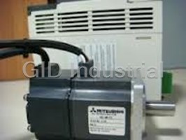
Mitsubishi HCMF73KUE Servo Motor - SERVO MOTOR AC

Mitsubishi HC-PQ43KUE SERVO MOTOR
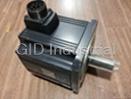
Mitsubishi HC-SF352 Servo Motor 3.5W
Request a Quote

The quote request has been received
Close

Facing challenges or have inquiries? Feel free to contact us!
Call Us +1-469-283-2440
What they say about us
FANTASTIC RESOURCE
One of our top priorities is maintaining our business with precision, and we are constantly looking for affiliates that can help us achieve our goal. With the aid of GID Industrial, our obsolete product management has never been more efficient. They have been a great resource to our company, and have quickly become a go-to supplier on our list!
Bucher Emhart Glass
EXCELLENT SERVICE
With our strict fundamentals and high expectations, we were surprised when we came across GID Industrial and their competitive pricing. When we approached them with our issue, they were incredibly confident in being able to provide us with a seamless solution at the best price for us. GID Industrial quickly understood our needs and provided us with excellent service, as well as fully tested product to ensure what we received would be the right fit for our company.
Fuji
HARD TO FIND A BETTER PROVIDER
Our company provides services to aid in the manufacture of technological products, such as semiconductors and flat panel displays, and often searching for distributors of obsolete product we require can waste time and money. Finding GID Industrial proved to be a great asset to our company, with cost effective solutions and superior knowledge on all of their materials, it’d be hard to find a better provider of obsolete or hard to find products.
Applied Materials
CONSISTENTLY DELIVERS QUALITY SOLUTIONS
Over the years, the equipment used in our company becomes discontinued, but they’re still of great use to us and our customers. Once these products are no longer available through the manufacturer, finding a reliable, quick supplier is a necessity, and luckily for us, GID Industrial has provided the most trustworthy, quality solutions to our obsolete component needs.
Nidec Vamco
TERRIFIC RESOURCE
This company has been a terrific help to us (I work for Trican Well Service) in sourcing the Micron Ram Memory we needed for our Siemens computers. Great service! And great pricing! I know when the product is shipping and when it will arrive, all the way through the ordering process.
Trican Well Service
GO TO SOURCE
When I can't find an obsolete part, I first call GID and they'll come up with my parts every time. Great customer service and follow up as well. Scott emails me from time to time to touch base and see if we're having trouble finding something.....which is often with our 25 yr old equipment.
ConAgra Foods